www.erni.com
ERNI MicroStac
Catalog E 074521 07/06 Edition 6

2 www.ERNI.com/contact/
Catalog E 074505 01/02 Edition 3
www.erni.com
Catalog E 074521 07/06 Edition 7

3www.ERNI.com/contact/
Catalog E 074521 07/06 Edition 7
Table of Contents
Applications. . . . . . . . . . . . . . . . . . . . . . . . . . . . . . . . . . . . . . . . . . . . . . . . . . . . . . . . . . . . . . . . . . . . . . . . . . . . . . . . . . . . . . . . . . . 4Technical Features. . . . . . . . . . . . . . . . . . . . . . . . . . . . . . . . . . . . . . . . . . . . . . . . . . . . . . . . . . . . . . . . . . . . . . . . . . . . . . . . . . . . . . 4Electrical And Mechanical Characteristics . . . . . . . . . . . . . . . . . . . . . . . . . . . . . . . . . . . . . . . . . . . . . . . . . . . . . . . . . . . . . . . . . . . . 66 Pin Single Row Version . . . . . . . . . . . . . . . . . . . . . . . . . . . . . . . . . . . . . . . . . . . . . . . . . . . . . . . . . . . . . . . . . . . . . . . . . . . . . . . . 812 Pin Single Row Version . . . . . . . . . . . . . . . . . . . . . . . . . . . . . . . . . . . . . . . . . . . . . . . . . . . . . . . . . . . . . . . . . . . . . . . . . . . . . . 1050 Pin Dual Row Version. . . . . . . . . . . . . . . . . . . . . . . . . . . . . . . . . . . . . . . . . . . . . . . . . . . . . . . . . . . . . . . . . . . . . . . . . . . . . . . . 12Packaging . . . . . . . . . . . . . . . . . . . . . . . . . . . . . . . . . . . . . . . . . . . . . . . . . . . . . . . . . . . . . . . . . . . . . . . . . . . . . . . . . . . . . . . . . . . 14Mating Conditions for MicroStac . . . . . . . . . . . . . . . . . . . . . . . . . . . . . . . . . . . . . . . . . . . . . . . . . . . . . . . . . . . . . . . . . . . . . . . . . . 15More SMT Connectors from ERNI . . . . . . . . . . . . . . . . . . . . . . . . . . . . . . . . . . . . . . . . . . . . . . . . . . . . . . . . . . . . . . . . . . . . . . . . . 16Part Number Index . . . . . . . . . . . . . . . . . . . . . . . . . . . . . . . . . . . . . . . . . . . . . . . . . . . . . . . . . . . . . . . . . . . . . . . . . . . . . . . . . . . . 18

4 www.ERNI.com/contact/
Catalog E 074521 07/06 Edition 7
Applications
Sensor engineering: Light barriers, switchesMedical engineering: Intensive medical equipment, porta-
ble diagnosticsMobile communication: Mobile phones, PDAs, organizer,
memory modulesCar electronics: Car radios, mobile car phones,
mobile car office equipmentControl engineering: Mini PLCs, fieldbus modules, mini
solenoid sytemsFacility management: Signal and indicator devices, alarm
systems and bus modules
Technical Features
0
0,5
1
1,5
2
2,5
3
Temperature [¡C]
Current (A
Base curve [A] 2 1,95 1,9 1,82 1,72 1,6 1,45 1,28 1,05 0,75 0,45
Derating curve [A] 1,6 1,56 1,52 1,456 1,376 1,28 1,16 1,024 0,84 0,6 0,36
0 10 20 30 40 50 60 70 80 90 100 110 120 130
Derating CurveIn spite of the small design of the ERNI MicroStac series,they reach a high current rating. The contacts feature largeradiant surfaces to derive heat. The derating curve shows the50pin version without PCB.
5www.ERNI.com/contact/
Catalog E 074521 07/06 Edition 7
Technical Features
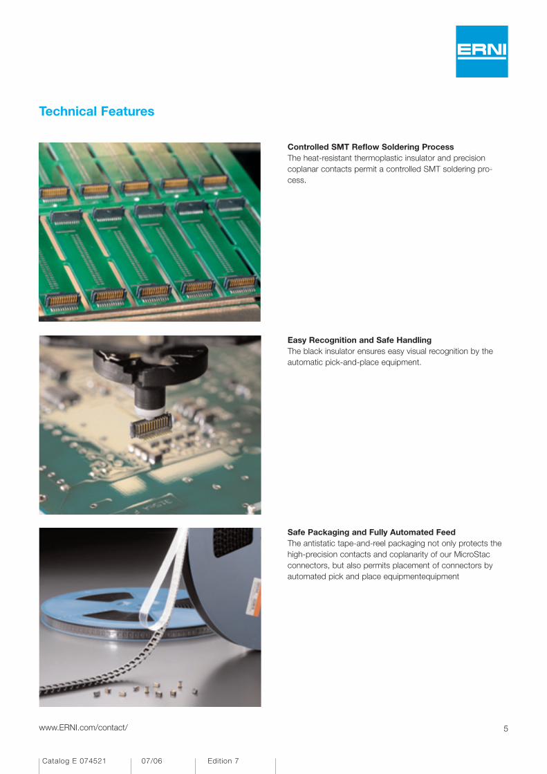
Controlled SMT Reflow Soldering ProcessThe heat-resistant thermoplastic insulator and precisioncoplanar contacts permit a controlled SMT soldering pro-cess.
Easy Recognition and Safe HandlingThe black insulator ensures easy visual recognition by theautomatic pick-and-place equipment.
Safe Packaging and Fully Automated FeedThe antistatic tape-and-reel packaging not only protects thehigh-precision contacts and coplanarity of our MicroStacconnectors, but also permits placement of connectors byautomated pick and place equipmentequipment
6 www.ERNI.com/contact/
Catalog E 074521 07/06 Edition 7
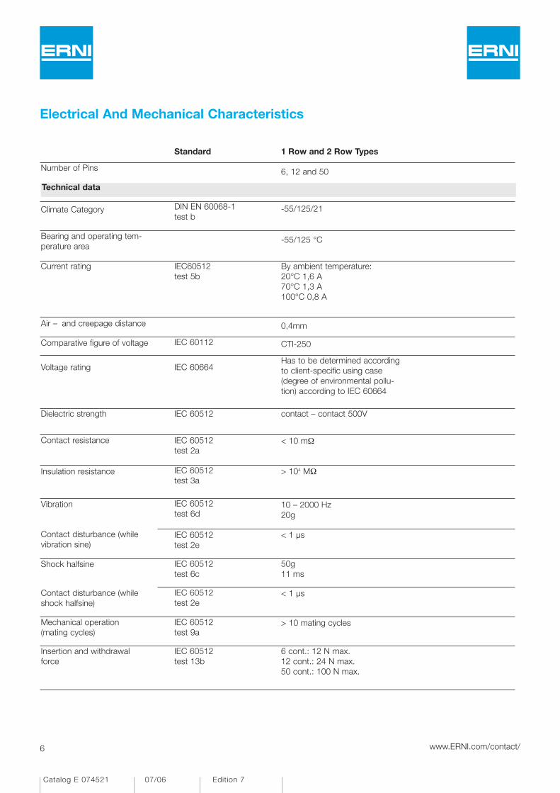
Electrical And Mechanical Characteristics
6 cont.: 12 N max.12 cont.: 24 N max.50 cont.: 100 N max.
IEC 60512 test 13b
Insertion and withdrawalforce
> 10 mating cyclesIEC 60512 test 9a
Mechanical operation(mating cycles)
< 1 µsIEC 60512 test 2e
Contact disturbance (whileshock halfsine)
50g11 ms
IEC 60512 test 6c
Shock halfsine
< 1 µsIEC 60512 test 2e
Contact disturbance (whilevibration sine)
10 – 2000 Hz20g
IEC 60512 test 6d
Vibration
> 104 MΩIEC 60512 test 3a
Insulation resistance
< 10 mΩIEC 60512 test 2a
Contact resistance
contact – contact 500VIEC 60512 Dielectric strength
Has to be determined accordingto client-specific using case (degree of environmental pollu-tion) according to IEC 60664
IEC 60664Voltage rating
CTI-250IEC 60112Comparative figure of voltage
0,4mmAir – and creepage distance
By ambient temperature:20°C 1,6 A70°C 1,3 A100°C 0,8 A
IEC60512test 5b
Current rating
-55/125 °CBearing and operating tem-perature area
-55/125/21DIN EN 60068-1test b
Climate Category
Technical data
6, 12 and 50Number of Pins
1 Row and 2 Row TypesStandard

7www.ERNI.com/contact/
Catalog E 074521 07/06 Edition 7
Electrical And Mechanical Characteristics
no flame-retardent additives, no toxic additives allow easy recyclingrecycling
Enviroment compatibility
SnPlating
Cu alloyBase material
Termination area
Gold platedPlating
Cu alloyBase material
Contact and mating area
E 47960UL file
UL 94 V-0UL flame rating
CTI 250IEC 60112CTI value
PA 46 Housing: plastic material (symbol)
Materials
< 0,1mmCoplanarity
10s at 260°C IEC 68-2-20SMT-Reflow soldering temperature max.
3,5s at 350°C IEC 68-2-20Hand soldering temperature max.
Process-conditions
6, 12 and 50Number of Pins
1 Row and 2 Row TypesStandard

8 www.ERNI.com/contact/
Catalog E 074521 07/06 Edition 7
6 Pin Single Row Version
Dimensional Drawing
1,45
1,15
4,35
3,9
0,425
Pos. 1
0,845 x 0,8 =
0,9
3,2
Koplanarität der Anschlüsse 0,1mmCoplanarity area of termination 0,1mm
< _ < _
7,16
3,95
1
-0,030,6 0,8 -0,03
6,3 ±0,03
±0,03
4
0,8
5 x 0,8 =
1,15
1,65
Leiterplatten-Layout VorschlagPCB-Layout Proposal
Pos. 1
Bezugslinie für gestecktes PaarReferenceline for mated pair
4,3
1,35
±0,036,3+0,03
0,65+0,03
0,85
0,44
The SMT connector series MicroStac with 0.8 mm pitchand with SMT termination is based on a hermaphroditicdesign. As result of this the male and the female connectorare identical. The same style for male and female connectormeet the requirement for a economical connector solutionin modern applications in electronics. The dual-sided PCBapplication contact principle provides for a tilt-proof andinsertion-proof connector position on the PCB. The grippersurface is integrated within the insulator body. This obviatesthe need for the standard assembly hood. Optionally, versi-ons featuring positioning pegs are also available. Using theMicroStac a board-to-board height from 5.0 mm up to6.5 mm is achieved.
All
dim
ensi
ons
in m
m

9www.ERNI.com/contact/
Catalog E 074521 07/06 Edition 7
Single row with peg, tape and reel, 1500 pcs/reel
Ordering Information
Part NumberHeightConfiguration
1147116
No. ofPins
6 Pin Single Row Version
Bezugslinie für gestecktes Paar
Referenceline for mated pair
Bezugslinie für gestecktes Paar
Referenceline for mated pair
0,85
4,2
5
7,5
3,75
5
5,5
1,45
2,6
50 polig
50 pin
6, 12 polig
6, 12 pin
All dimensions in mm
10 www.ERNI.com/contact/
Catalog E 074521 07/06 Edition 7
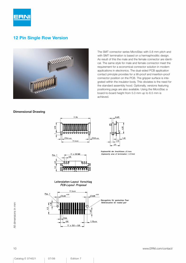
12 Pin Single Row Version
Dimensional Drawing
1,45
4,35
0,425
1,15
3,9
<_ < _
Koplanarität der Anschlüsse 0,1mmCoplanarity area of termination 0,1mmPos. 1
0,8
11 x 0,8 =
3,2
8,8
0,9
3,95
±0,0311,1
0,6 -0,03 0,8 -0,03
1
11,96
0,8
11 x 0,8 = 8,8
1,65
1,15±0,03
Pos. 1
Leiterplatten-Layout VorschlagPCB-Layout Proposal
Bezugslinie für gestecktes PaarReferenceline for mated pair
+0,030,65
+0,03
±0,0311,1
0,44
0,85
1,35
4,3
The SMT connector series MicroStac with 0.8 mm pitch andwith SMT termination is based on a hermaphroditic design.As result of this the male and the female connector are identi-cal. The same style for male and female connector meet therequirement for a economical connector solution in modernapplications in electronics. The dual-sided PCB applicationcontact principle provides for a tilt-proof and insertion-proofconnector position on the PCB. The gripper surface is inte-grated within the insulator body. This obviates is the need forthe standard assembly hood. Optionally, versions featuringpositioning pegs are also available. Using the MicroStac aboard-to-board height from 5.0 mm up to 6.5 mm isachieved.
All
dim
ensi
ons
in m
m

11www.ERNI.com/contact/
Catalog E 074521 07/06 Edition 7
Single row with peg, tape and reel, 1500 pcs/reel
Ordering Information
Part NumberHeightConfiguration
11471212
No. ofPins
12 Pin Single Row Version
All dimensions in mm
Bezugslinie für gestecktes Paar
Referenceline for mated pair
Bezugslinie für gestecktes Paar
Referenceline for mated pair
0,85
4,2
5
7,5
3,75
5
5,5
1,45
2,6
50 polig
50 pin
6, 12 polig
6, 12 pin
12 www.ERNI.com/contact/
Catalog E 074521 07/06 Edition 7
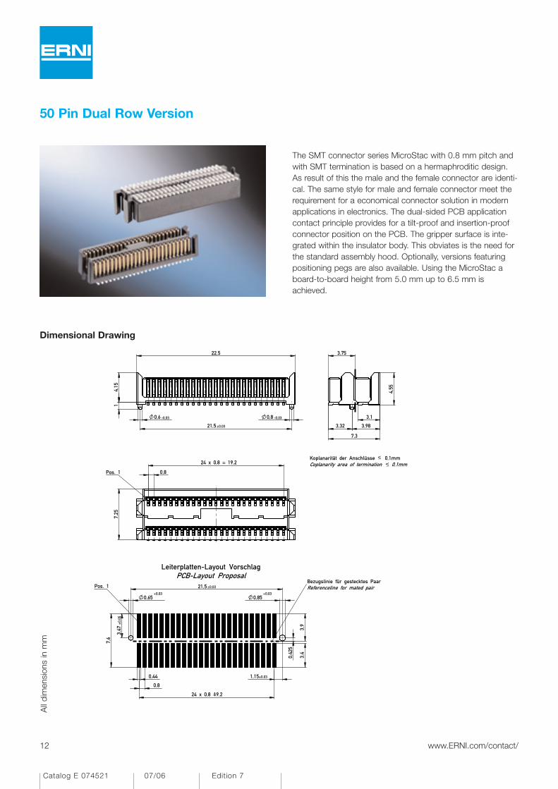
50 Pin Dual Row Version
Dimensional Drawing
3,75
3,98
7,3
4,55
3,32
3,1
Koplanarität der Anschlüsse 0,1mmCoplanarity area of termination 0,1mm
±0,03
4,15
21,5
1
-0,030,6 0,8 -0,03
22,5
< _< _
Pos. 1
7,25
0,8
24 x 0,8 = 19,2
0,42
5
3,9
Leiterplatten-Layout VorschlagPCB-Layout Proposal
Pos. 1Bezugslinie für gestecktes PaarReferenceline for mated pair±0,03
+0,030,65
±0,
05
+0,03
7,6
3,47
0,44
0,8
0,85
19,224 x 0,8 =
1,15±0,03
21,5
3,4
The SMT connector series MicroStac with 0.8 mm pitch andwith SMT termination is based on a hermaphroditic design.As result of this the male and the female connector are identi-cal. The same style for male and female connector meet therequirement for a economical connector solution in modernapplications in electronics. The dual-sided PCB applicationcontact principle provides for a tilt-proof and insertion-proofconnector position on the PCB. The gripper surface is inte-grated within the insulator body. This obviates is the need forthe standard assembly hood. Optionally, versions featuringpositioning pegs are also available. Using the MicroStac aboard-to-board height from 5.0 mm up to 6.5 mm isachieved.
All
dim
ensi
ons
in m
m

13www.ERNI.com/contact/
Catalog E 074521 07/06 Edition 7
Dual row with peg, tape and reel, 800 pcs/reel
Ordering Information
Part NumberHeightConfiguration
11471350
No. ofPins
50 Pin Dual Row Version
All dimensions in mm
Bezugslinie für gestecktes Paar
Referenceline for mated pair
Bezugslinie für gestecktes Paar
Referenceline for mated pair
0,85
4,2
5
7,5
3,75
5
5,5
1,45
2,6
50 polig
50 pin
6, 12 polig
6, 12 pin

14 www.ERNI.com/contact/
Catalog E 074521 07/06 Edition 7
Packaging
6 Pin Version
16,5
Abspulrichtung - Reel off Direction
Pos. 1
8
4
Verpackt in Gurtverpackung - Tape on Reel PackagingVerpackungseinheit: 1500 Stück- Packaging unit: 1500 pcs
150
330
12 Pin Version
Abspulrichtung - Reel off Direction
Pos. 1
8
4Verpackt in Gurtverpackung - Tape on Reel PackagingVerpackungseinheit: 1500 Stück- Packaging unit: 1500 pcs
150
330
24,5
50 Pin Version
44,5
Pos. 1
Abspulrichtung - Reel off Direction
4 12
Verpackt in Gurtverpackung - Tape on Reel PackagingVerpackungseinheit: 800 Stück- Packaging unit: 800 pcs
150
330
All
dim
ensi
ons
in m
m

15www.ERNI.com/contact/
Catalog E 074521 07/06 Edition 7
Mating Conditions for MicroStac
Misalignment Tolerances longitudinal: ±0.7mm; transverse: ±0.5mm
0.7 0.5
Angular Inclination Tolerances longitudinal: ±4°; transverse: ±4°
"Board to Board" Height distance: 5.0-6.5 mm
4˚
4˚
6.5
5.0
-
All
dim
ensi
ons
in m
m

16 www.ERNI.com/contact/
Catalog E 074521 07/06 Edition 7
More SMT Connectors from ERNI
Right Angle Surface Mount D-Sub ConnectorModern Sub Rack Technology is increasing the demand forSMT components along with the requirement for the connec-tors supporting this technology. ERNI is meeting the need bydeveloping a new generation of the classic I/O D-Subconnector which uses surface mount technology.
High Speed Differential Connector SystemERmet zeroXT for 10 GBit/sFor modern high speed backplane designs with data trans-mission rates up to 10 Gbit/s ERNI has developed the newERmet zeroXT Connector System with 100 Ohm matcheddifferential impedance for enhanced signal integrity. The newconnector system is specifically designed to meet the chal-lenging electrical performance needs required by next gene-ration designs utilizing low voltage differential signaling. TheERmet zeroXT now offers an innovative shielding design andSMT termination to provide very low cross-talk, low skewand improved trace routing. Additional features and benefitsare a reliable female contact design, different mating levelsand a rugged housing.
SMC 1.27 mm pitchSMC connectors are excellently suited for efficient proces-sing in modern SMT soldering systems. Easy population,optimum seating and attachment by integrated retainingclips, and the exact position of the connection pins makeSMC connectors into a real SMT component. We supplySMC connectors on a reel for the automatic assembly.
Single Port Mod Jacks• Various pin configurations e.g. RJ 11, RJ 45• Shielded or unshielded• Standard or ultra low profile• Right angle Versions• SMT termination• LED versions

17www.ERNI.com/contact/
Catalog E 074521 07/06 Edition 7
114711 . . . . . . . . . . 9114712 . . . . . . . . . 11114713 . . . . . . . . . 13
18 www.ERNI.com/contact/
Catalog E 074521 07/06 Edition 7
Part Number Index
Part Number Page

Catalog E 074519 10/01 Edition 2 Katalog D 004045 10/01 Ausgabe 1
Member
Catalog E 074521 07/06 Edition 7

20 www.ERNI.com/contact/
Catalog E 074521 07/06 Edition 7
ERNI Electronics GmbH 2006 • Printed in Germany.A policy of continuous improvement is followed and the right to alter any published data without notice is reserved.
ERNI Electronics GmbH Europe South America AfricaSeestrasse 9, Postfach73099 Adelberg, DeutschlandTel +49 (0)71 66 50-0Fax +49 (0)71 66 [email protected]
ERNI Electronics, Inc. North America Canada Mexico3005 E. Boundary TerraceMidlothian, VA 23112 USATel +1 (804) 228-4100Fax +1 (804) [email protected]
ERNI Asia Holding Pte Ltd. AsiaBlk 4008 Ang Mo Kio Avenue 10#04-01/02 Techplace ISingapore 569625Tel +65 6 555 5885Fax +65 6 555 [email protected]
www.erni.com
Catalog E 074521 07/06 Edition 7
Recommended
![6. Comprehensive List of Publications Prof. Dr. Daniel Erni...SEV/VSE 3/97, vol. 88, no. 3, pp. 11-16, March 1997. [5] D. Erni, M. M. Spühler, and J. Fröhlich, "A generalized evolutionary](https://img.pdfslide.us/doc/110x75/61290447815d347339455814/6-comprehensive-list-of-publications-prof-dr-daniel-erni-sevvse-397-vol.jpg)