Enhancing Performance with Pipelining
Slides developed by Rami Abielmona and modified by Miodrag Bolic
High-Level Computer Systems Design

Presentation Outline (1)
What is pipelining ? Pipeline Taxonomies Instruction Pipelines MIPS Instruction Pipeline Pipeline Hazards MIPS Pipelined Datapath Load Word Instruction Example Pipeline Datapath Example Pipeline Control Pipeline Instruction Example

Presentation Outline (2)
Pipeline Hazards Control Hazards Data Hazards Detecting Data Hazards Resolving Data Hazards Forwarding Example Stalling Example Branch Hazards Branching Example Key terms
What is Pipelining ? (1)
There are two main ways to increase the performance of a processor through high-level system architecture– Increasing the memory access speed– Increasing the number of supported concurrent
operations Pipelining ! Parallelism ?
Pipelining is the process by which instructions are parallelized over several overlapping stages of execution, in order to maximize datapath efficiency
What is Pipelining ? (2)
Pipelining is analogous to many everyday scenarios– Car manufacturing process– Batch laundry jobs– Basically, any assembly-line operation applies
Two important concepts:– New inputs are accepted at one end before previously
accepted inputs appear as outputs at the other end;– The number of operations performed per second is increased,
even though the elapsed time needed to perform any one operation remains the same
What is Pipelining ? (3)
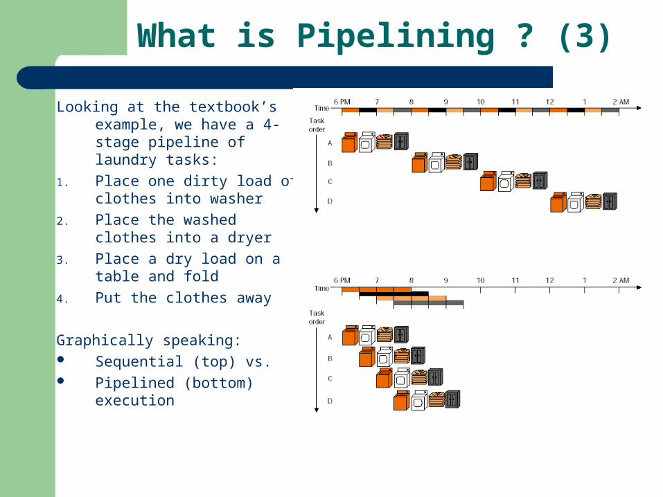
Looking at the textbook’s example, we have a 4-stage pipeline of laundry tasks:
1. Place one dirty load of clothes into washer
2. Place the washed clothes into a dryer
3. Place a dry load on a table and fold
4. Put the clothes away
Graphically speaking: Sequential (top) vs. Pipelined (bottom) execution

Pipeline Taxonomies
There are two types of pipelines used in computer systems– Arithmetic pipelines
Used to pipeline data intensive functionalities
– Instruction pipelines Used to pipeline the basic instruction fetch and execute sequence
Other classifications include– Linear vs. nonlinear pipelines
Presence (or lack) of feedforward and feedback paths between stages
– Static vs. dynamic pipelines Dynamic pipelines are multifunctional, taking on a different form
depending on the function being executed
– Scalar vs. vector pipelines Vector pipelines specifically target computations using vector data
MIPS Instruction Pipeline (1)
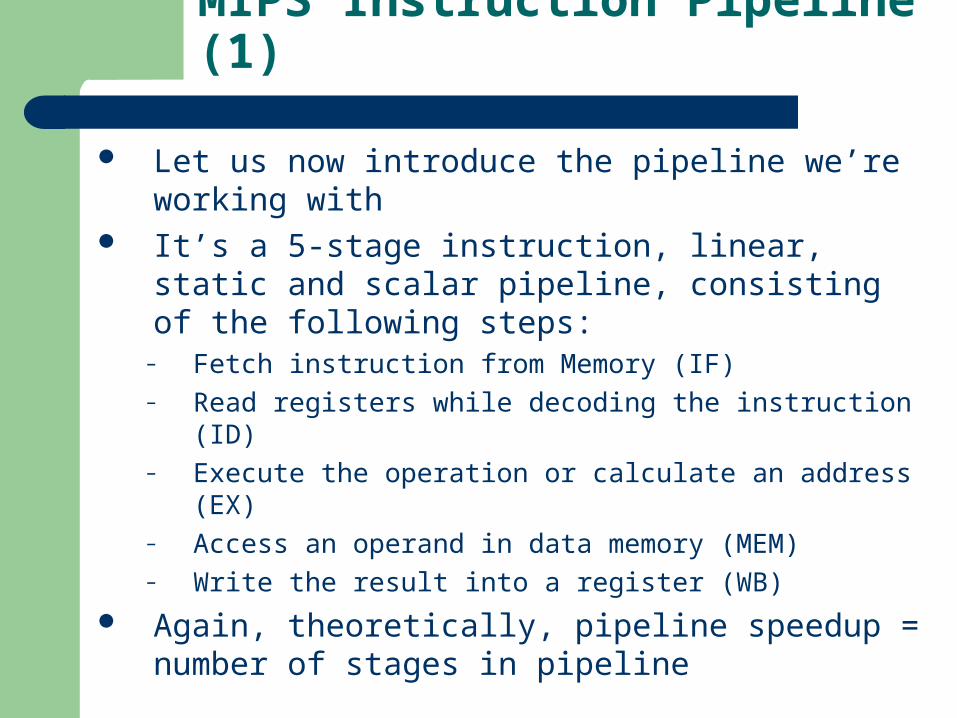
Let us now introduce the pipeline we’re working with It’s a 5-stage instruction, linear, static and scalar
pipeline, consisting of the following steps:– Fetch instruction from Memory (IF)– Read registers while decoding the instruction (ID)– Execute the operation or calculate an address (EX)– Access an operand in data memory (MEM)– Write the result into a register (WB)
Again, theoretically, pipeline speedup = number of stages in pipeline

MIPS Instruction Pipeline (2)
Inst. Fetch (2ns), Reg. read/write (1ns), ALU op. (2ns), Data access (2ns)

Single Cycle, Multiple Cycle, vs. Pipeline [1]
Clk
Cycle 1
Multiple Cycle Implementation:
Ifetch Reg Exec Mem Wr
Cycle 2 Cycle 3 Cycle 4 Cycle 5 Cycle 6 Cycle 7 Cycle 8 Cycle 9 Cycle 10
Load Ifetch Reg Exec Mem Wr
Ifetch Reg Exec Mem
Load Store
Pipeline Implementation:
Ifetch Reg Exec Mem WrStore
Clk
Single Cycle Implementation:
Load Store Waste
Ifetch
R-type
Ifetch Reg Exec Mem WrR-type
Cycle 1 Cycle 2
Why Pipeline?
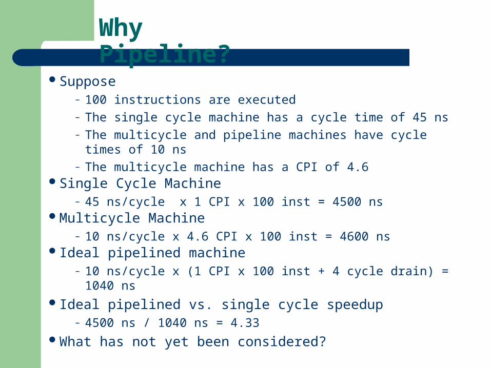
Suppose – 100 instructions are executed– The single cycle machine has a cycle time of 45 ns– The multicycle and pipeline machines have cycle times of 10 ns– The multicycle machine has a CPI of 4.6
Single Cycle Machine– 45 ns/cycle x 1 CPI x 100 inst = 4500 ns
Multicycle Machine– 10 ns/cycle x 4.6 CPI x 100 inst = 4600 ns
Ideal pipelined machine– 10 ns/cycle x (1 CPI x 100 inst + 4 cycle drain) = 1040 ns
Ideal pipelined vs. single cycle speedup– 4500 ns / 1040 ns = 4.33
What has not yet been considered?
MIPS Instruction Pipeline (3) [2]
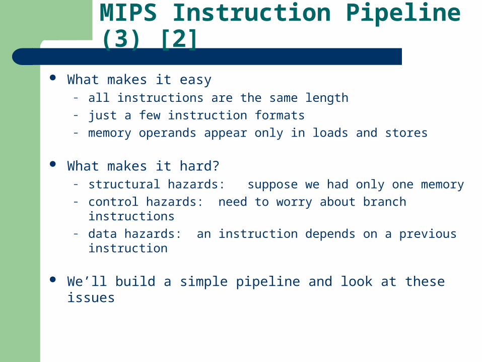
What makes it easy– all instructions are the same length– just a few instruction formats– memory operands appear only in loads and stores
What makes it hard?– structural hazards: suppose we had only one memory– control hazards: need to worry about branch instructions– data hazards: an instruction depends on a previous instruction
We’ll build a simple pipeline and look at these issues
Pipeline Hazards [1]
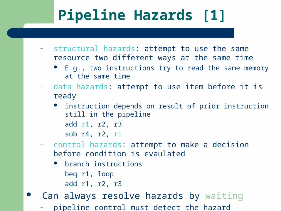
– structural hazards: attempt to use the same resource two different ways at the same time E.g., two instructions try to read the same memory at the same time
– data hazards: attempt to use item before it is ready instruction depends on result of prior instruction still in the pipeline
add r1, r2, r3
sub r4, r2, r1
– control hazards: attempt to make a decision before condition is evaulated branch instructions
beq r1, loop
add r1, r2, r3
Can always resolve hazards by waiting– pipeline control must detect the hazard– take action (or delay action) to resolve hazards

MIPS Pipelined Datapath (1)
What do we need to split the datapath into stages ?

MIPS Pipelined Datapath (2)
Pipeline registers (buffers) are similar to multicycle processor design

Load Word Instruction (1)
Instruction fetch stage

Load Word Instruction (2)
Instruction decode and register file read stage
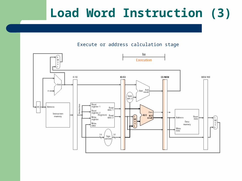
Load Word Instruction (3)
Execute or address calculation stage
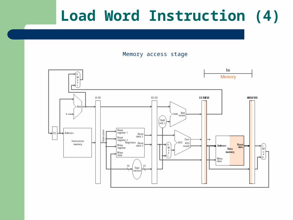
Load Word Instruction (4)
Memory access stage
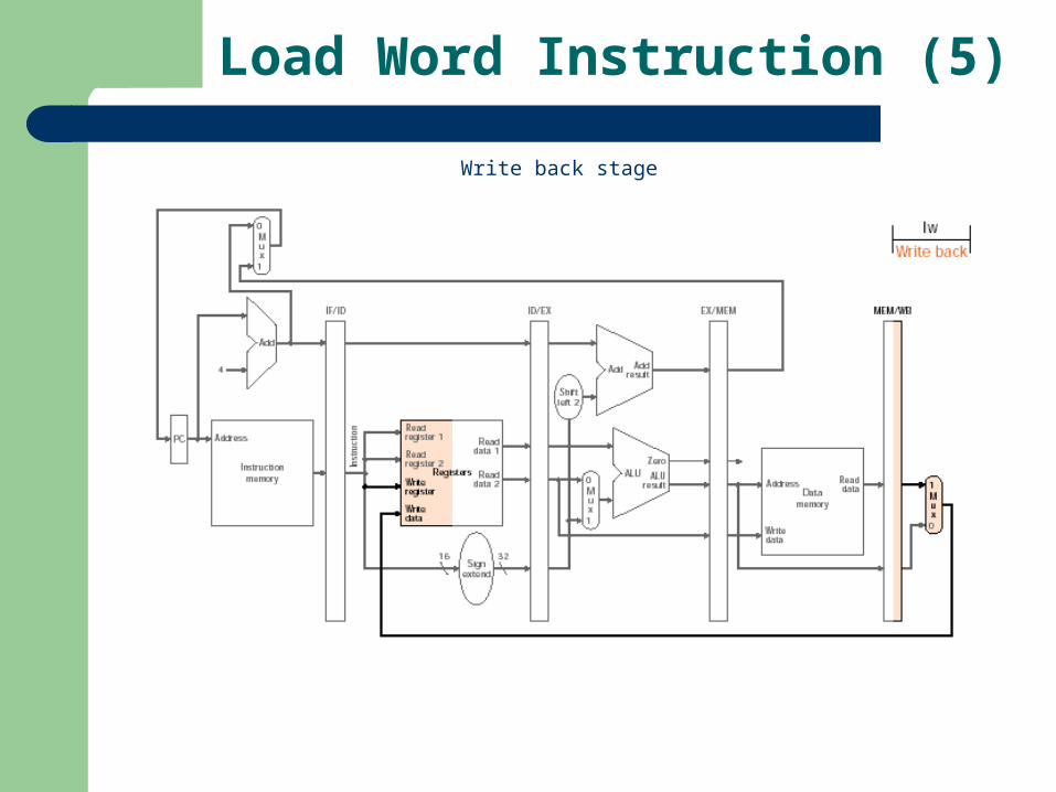
Load Word Instruction (5)
Write back stage

Load Word Corrected Datapath
Write register number comes from the MEM/WB pipeline register along with the data
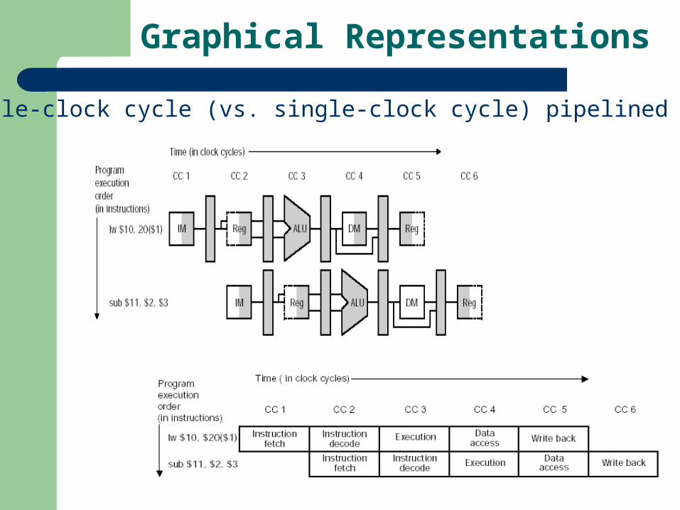
Graphical Representations
Multiple-clock cycle (vs. single-clock cycle) pipelined diagrams

Pipeline Datapath Example (1)
Single-cycle pipeline diagram with one instruction on the pipeline

Pipeline Datapath Example (2)
Single-cycle pipeline diagram with two instructions on the pipeline

Pipeline Control (1)
What control signals are required ? First, notice that the pipeline registers are written every clock
cycle, hence do not require explicit control signals, otherwise:– Instruction fetch and PC increment
Again, asserted at every clock cycle
– Instruction decode and register file read Again, asserted at every clock cycle
– Execution and address calculation Need to select the result register, the ALU operation, and either Read
data 2 or the sign-extended immediate for the ALU
– Memory access Need to read from memory, write to memory or complete branch
– Write back Need to send back either ALU result or memory value to the register file

Pipeline Control (2)
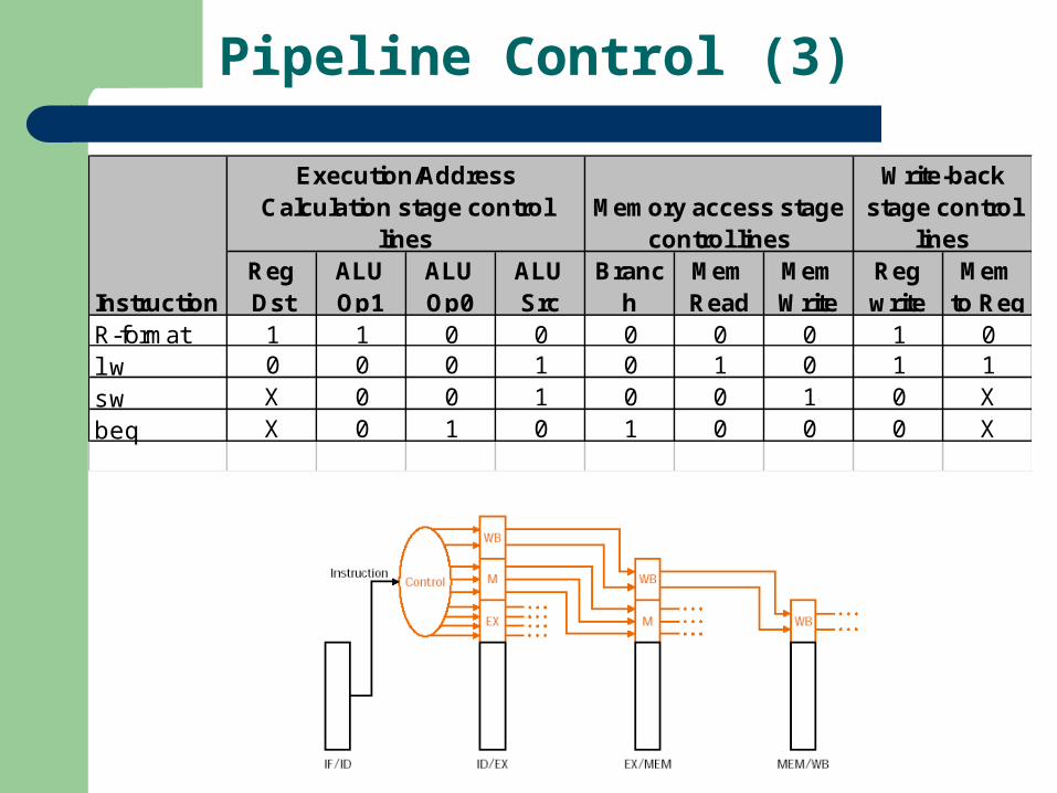
Pipeline Control (3)
Execution/Address Calculation stage control
linesMemory access stage
control lines
Write-back stage control
lines
InstructionReg Dst
ALU Op1
ALU Op0
ALU Src
Branch
Mem Read
Mem Write
Reg write
Mem to Reg
R-format 1 1 0 0 0 0 0 1 0lw 0 0 0 1 0 1 0 1 1sw X 0 0 1 0 0 1 0 Xbeq X 0 1 0 1 0 0 0 X

Pipeline Datapath with Control

Pipeline Instruction Example (1)

Pipeline Instruction Example (2)
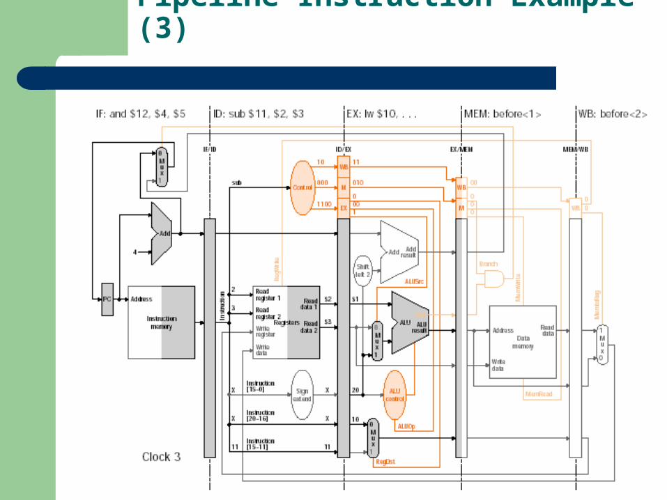
Pipeline Instruction Example (3)

Pipeline Instruction Example (4)

Pipeline Instruction Example (5)

Pipeline Instruction Example (6)
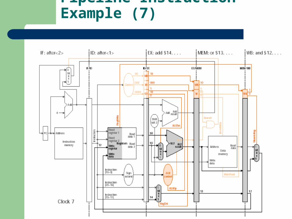
Pipeline Instruction Example (7)

Pipeline Instruction Example (8)

Pipeline Instruction Example (9)

Pipeline Hazards
Structural hazard– Occurs when a combination of instructions is not supported by the datapath– For example, a unified memory unit would need to be accessed in stages 1 (IF)
and 4 (MEM), which would cause a contention– Pipeline outright fails in the presence of structural hazards
Control hazard– Occurs when a decision is made based on the results of one instructions, while
others are executing– For example, a branch instruction is either taken or not– Solutions that exist are stalling and predicting
Data hazard– Occurs when an instruction depends on the results of an instruction resident on
the pipeline– For example, adding two register contents and storing their result into a third
register, then using that register’s contents for another operation– Solutions that exist are based on forwarding

Control Hazards - Stalling
Three major solutions– Stall– Predict– Delayed branch slot
Stalling involves always waiting for the PC to be updated with the correct address before moving on
A pipeline stall (or bubble) allows us to perform this wait Quite costly, as we have to stall even if the branch fails

Control Hazards - Predicting
Predicting involves guessing whether the branch is taken or not, and acting on that guess
– If correct, then proceed with normal pipeline execution– If incorrect, then stall pipeline execution

Control Hazards – Delayed branch
Delayed branch involves executing the next sequential instruction with the branch taking place after that delayed branch slot
The assembler automatically adjusts the instructions to make it transparent from the programmer
– The instruction has to be safe, as in it shouldn’t affect the branch– Longer pipelines requires the use of more branch delay slots– Actual MIPS architecture solution

Data Hazards – Forwarding (1)
Forwarding involves providing the inputs to a stage of one instruction before the completion of another instruction
Valid if destination stage is later in time than the source stage Left diagram shows typical forwarding scenario (add then sub) Right diagram shows that we still need a stall in the case of a load-
use data hazard (load then R-type)

Data Hazards – Forwarding (2)
sub $2, $1, $3
and $12, $2, $5
or $13, $6, $2
add $14, $2, $2
sw $14, 100($2)
Data Hazards – Crude Solution
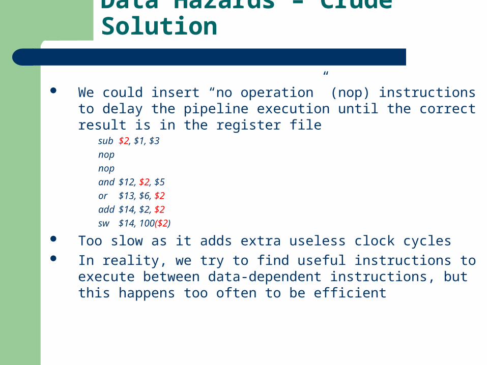
We could insert “no operation” (nop) instructions to delay the pipeline execution until the correct result is in the register file
sub $2, $1, $3
nop
nop
and $12, $2, $5
or $13, $6, $2
add $14, $2, $2
sw $14, 100($2)
Too slow as it adds extra useless clock cycles In reality, we try to find useful instructions to execute between data-
dependent instructions, but this happens too often to be efficient

Data Hazards – Detection (1)
Let us try to formalize detecting a data hazard
1. EX/MEM.RegisterRd = ID/EX.RegisterRs
2. EX/MEM.RegisterRd = ID/EX.RegisterRt
3. MEM/WB.RegisterRd = ID/EX.RegisterRs
4. MEM/WB.RegisterRd = ID/EX.RegisterRtsub $2, $1, $3
and $12, $2, $5 Data hazard of type #1
or $13, $6, $2 Data hazard of type #4
add $14, $2, $2 No data hazard – register file
sw $14, 100($2) No data hazard – correct operation
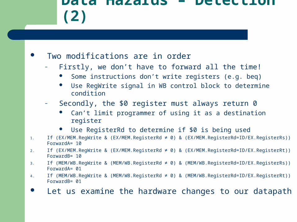
Data Hazards – Detection (2)
Two modifications are in order– Firstly, we don’t have to forward all the time!
Some instructions don’t write registers (e.g. beq) Use RegWrite signal in WB control block to determine condition
– Secondly, the $0 register must always return 0 Can’t limit programmer of using it as a destination register Use RegisterRd to determine if $0 is being used
1. If (EX/MEM.RegWrite & (EX/MEM.RegisterRd ≠ 0) & (EX/MEM.RegisterRd=ID/EX.RegisterRs)) ForwardA= 10
2. If (EX/MEM.RegWrite & (EX/MEM.RegisterRd ≠ 0) & (EX/MEM.RegisterRd=ID/EX.RegisterRt)) ForwardB= 10
3. If (MEM/WB.RegWrite & (MEM/WB.RegisterRd ≠ 0) & (MEM/WB.RegisterRd=ID/EX.RegisterRs)) ForwardA= 01
4. If (MEM/WB.RegWrite & (MEM/WB.RegisterRd ≠ 0) & (MEM/WB.RegisterRd=ID/EX.RegisterRt)) ForwardB= 01
Let us examine the hardware changes to our datapath

Data Hazards – Forwarding Unit (1)

Data Hazards – Forwarding Unit (2)
Mux control Source DescriptionForwardA = 00 ID/EX First ALU operand comes from RFForwardA = 01 EX/MEM First ALU operand forwarded from prior ALU resultForwardA = 10 MEM/WB First ALU operand forwarded from data memory or prior ALU resultForwardB = 00 ID/EX Second ALU operand comes from RFForwardB = 01 EX/MEM Second ALU operand forwarded from prior ALU resultForwardB = 10 MEM/WB Second ALU operand forwarded from data memory or prior ALU result
Remember that there is no hazard in the WB stage, because the register file is able to be written and read in the same stage

Data Hazards – Forwarding Unit (3)

Data Hazards – Forwarding Unit (4)

Forwarding Example (1)

Forwarding Example (2)

Forwarding Example (3)

Forwarding Example (4)
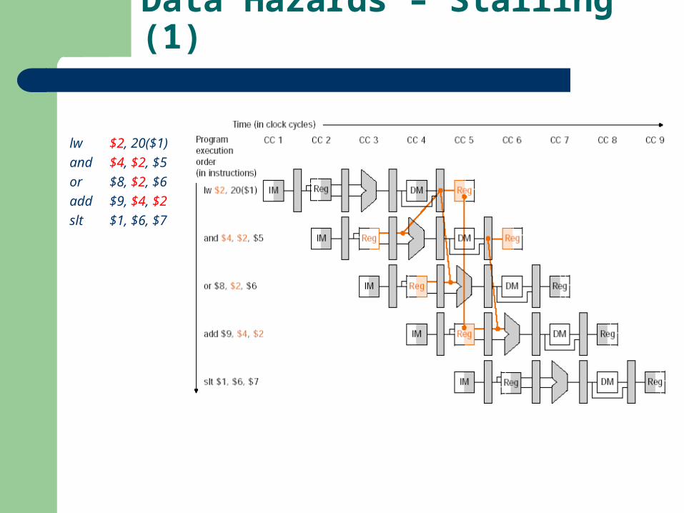
Data Hazards – Stalling (1)
lw $2, 20($1)
and $4, $2, $5
or $8, $2, $6
add $9, $4, $2
slt $1, $6, $7

Data Hazards – Stalling (2)
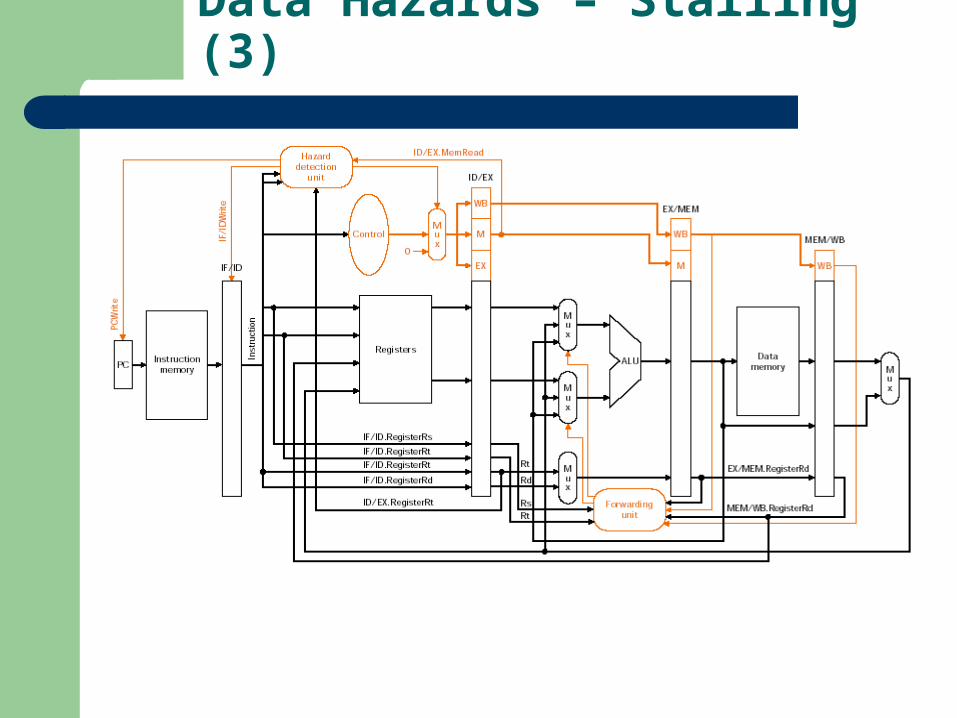
Let us try to formalize detecting a stalling data hazard If (ID/EX.MemRead & ((ID/EX.RegisterRt = IF/ID.RegisterRs) or (ID/EX.RegisterRt = IF/ID/RegisterRt)))
On the condition being true, we stall the pipeline!
Data Hazards – Stalling (3)
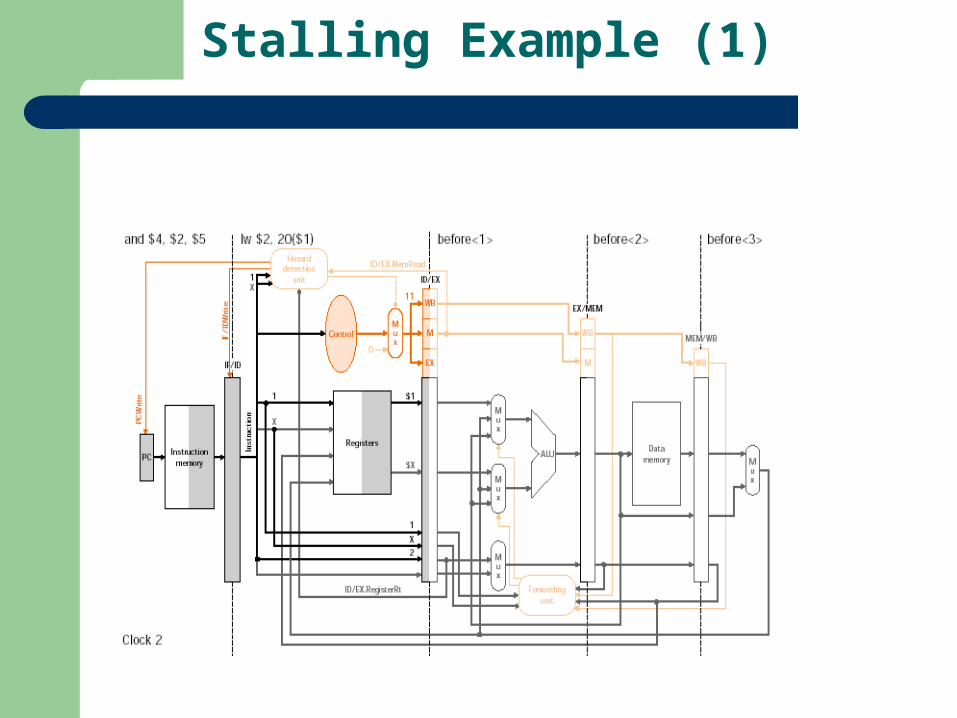
Stalling Example (1)

Stalling Example (2)

Stalling Example (3)
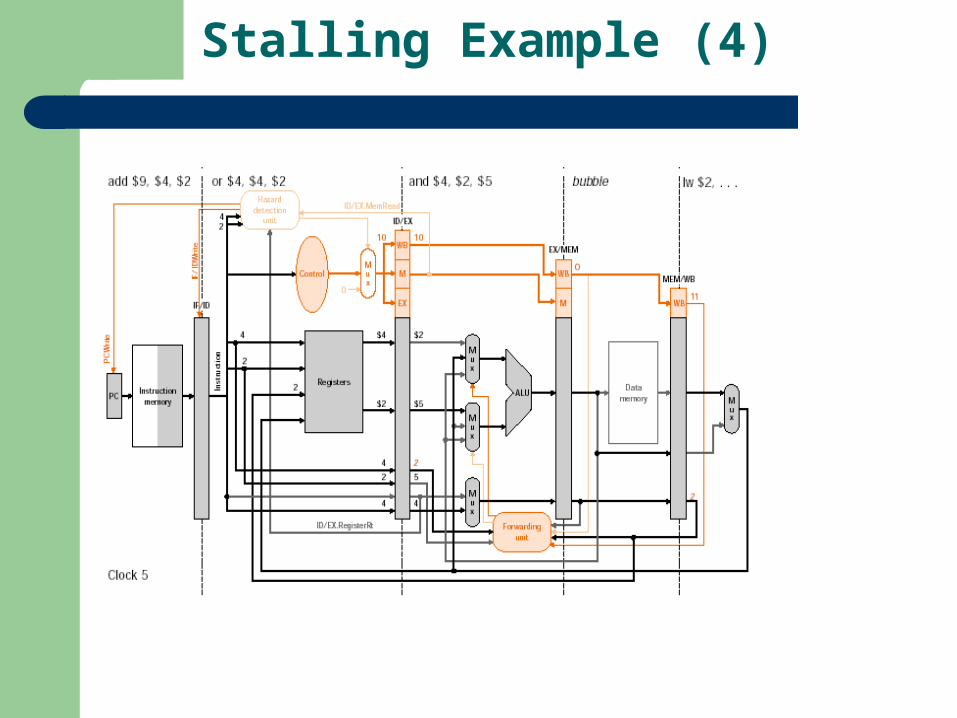
Stalling Example (4)

Stalling Example (5)

Stalling Example (6)
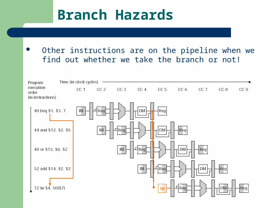
Branch Hazards
Other instructions are on the pipeline when we find out whether we take the branch or not!

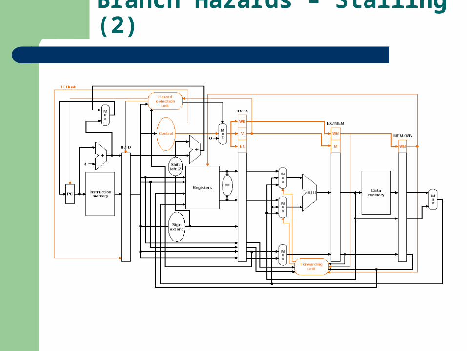
Branch Hazards – Stalling (1)
Two solutions– Assume branch is not taken– Dynamic branch prediction
We’ve already discussed the first solution– Note that three instruction stages have to be flushed when the
branch is taken– Done similarly to a data hazard stall (control values set to 0s)
We can increase branch performance by moving the branch decision to the ID stage (rather than the MEM stage)
– Branch target address calculated by moving adder into ID stage– Branch decision done by comparing Rs and Rt– Flushing the IF stage instruction involves nop instructions
Branch Hazards – Stalling (2)

Branching Example (1)

Branching Example (2)

Branch Hazards – Predicting (1)
Store, in a branch prediction buffer, the history of each branch instruction
– 1-bit requires one wrong prediction to update history table– 2-bits requires two wrong predictions to update history table
Key Terms and Review Points (1)
Pipelining vs. Parallelism Pipeline Stages Pipeline Taxonomies MIPS Instruction Pipeline Structural Hazards Control Hazards Data Hazards Pipeline Registers and Operation Pipeline Control Pipeline Throughput Pipeline Efficiency
Key Terms and Review Points (2)
Control Hazard Stalling Control Hazard Predicting Control Hazard Delayed Branch Data Hazard Forwarding Data Hazard Detection Forwarding Unit Data Hazard Stalling Branch Prediction Buffer
References
1. Mike Schulte, Computer Architecture ECE 201 , Lecture 11.
2. Morgan Kaufmann Website: Companion Web Site for Computer Organization and Design
Recommended