NASA Contractor Report 195454 if÷;>>/97P
Enhanced Analysis and Users Manual for
Radial-Inflow Turbine Conceptual
Design Code RTD
Arthur J. Glassman
University of ToledoToledo, Ohio
March 1995
Prepared forLewis Research Center
Under Grant NAG3-1165
National Aeronautics and
Space Administration
(I_ASA-CR-195454) ENHANCED ANALYSISAND USERS MANUAL FOR RAUIAL-INFL_W[URSINE CONCEPTUAL DESIGN CODE RTOFinal Contractor Report (ToledoUniv.) 24 o
G3/02
N95-23402
Unclas
0044401
https://ntrs.nasa.gov/search.jsp?R=19950017042 2020-05-15T03:33:03+00:00Z

Enhanced Analysis and Users Manual for
Radial-Inflow Turbine Conceptual Design Code RTD
Arthur J. Glassman*
University of Toledo
Toledo, Ohio 43606
SUMMARY
This report presents modifications made to a radial-inflow turbine conceptual design code,herein named RTD. The analysis is based on meanline flow through the stator and into the
rotor, and on equal span-fraction sectors at the rotor exit. Input design variables include flow,
power, and rotative speed. The output presents rotor tip diameter, flowpath dimensions,diagram velocities and angles, and efficiencies. Design parameters that can be variedinclude stator-exit angle, rotor-exit tip and hub radius ratios, and rotor swirl distribution.
Modifications were made to enhance the design-code capabilities consistent with those of
a companion off-design code. For pivoting vanes, a stator-endwall clearance flow was mod-eled by a vaneless-space flow through the clearance height. The rotor-inlet slip model andthe rotor-blade-number calculation were changed to allow rotor-blade-inlet angles other than
radial, thus permitting the use of swept rotor blades. Also for the rotor, splitter blades cannow be used between the full blades.
Added to the loss model were stator and rotor trailing-edge blockage losses and a
vaneless-space friction loss. The disk-friction model and the rotor-exit clearance loss corre-lation were modified. The Reynolds number dependency and level of the stator- androtor-passage losses were then calibrated based on experimental turbine performance datafrom several radial-inflow turbines. The selected model performed very well in predicting the
efficiency variation over a more than tenfold range of Reynolds number. The predictedefficiencies for three turbines had a maximum deviation of about I point as compared to
measured values.
This report also serves as an updated users manual for the RTD code. Program input and
output are described, and sample cases are included for illustration.
INTRODUCTION
Performing preliminary studies for power or propulsion systems requires the capability to
rapidly produce conceptual designs of the components in order to determine geometry,performance, and weight. The typical turbomachine "design" code enables a study of theinterrelationship of the number of stages, the flowpath dimensions, the gas velocities andflow angles, and the resultant variation in efficiency. A computer code capable of performing
*Resident Research Associate at NASA Lewis Research Center.
this function for a radial-inflow turbine was presented in reference 1.
A recent evaluation of the aforementioned code, herein named RTD, resulted in theidentification of desirable modifications. To make the modeling compatible with the
off-design code of reference 2, capabilities were required to accommodate pivoting stators,
swept (i.e., non-radial) rotor blades, and splitter blades. Also, the components of the lossmodel would have to be expanded to include stator and rotor trailing-edge losses and a
vaneless-space loss. The disk-friction and the rotor-exit clearance loss models needed
adjustment. Since the loss model of reference 1 was calibrated using only a singleexperimental point, the use of a more extensive database was highly desirable.
This report presents the analytical modeling associated with the above modifications. Also
presented is the calibration of the loss model using data from several turbines to define the
Reynolds number variation and the level of the efficiency. The report also serves as anupdated users manual for the RTD code. Program input and output are described and sam-
ple cases are included for illustration.
SYMBOLS
A
Deqf
gAh'
J
Kb_
KRe
Krr
L
I
I
n
Ap'
Ap"
qRe
r
t
U
V
W
W
(x
area, ft2'z
equivalent diameter, ft
Fanning friction factor
gravitational constant, (Ibm)(ft)/(Ibf)(sec 2)
turbine specific work, Btu/lbm
energy dimension constant, (ft)(Ib)/Btu
backface radius correction factor
Reynolds number correlation coefficient
radius-ratio correction factor
loss, Btu/lbm
surface length, ft
vaneless-space flow length, ft
number of blades
absolute total pressure drop, psf
relative total pressure drop, psf
blade-to-blade distance, ft
Reynolds number
radius, ft
trailing-edge thickness, ft
blade speed, ft/sec
absolute velocity, ft/sec
relative velocity, ft/sec
mass flow rate, Ibm/sec
absolute flow angle, deg
2
I_ relative flow angle, deg
y meridional flow angle, deg
F.,lim limiting radius ratio for correction factor
O momentum thickness, ft
viscosity, Ibm/(ft) (sec)
p density, Ibm/ft 3
Subscripts:
av average
b blading
bf backface
cl clearance
h hub
m mean
opt optimum
ref reference
r rotor or radial component
s stator
t tip
te trailing edge
tot total
u tangential component
VD velocity diagram
vs vaneless space
0 stator inlet
1 stator exit - outside trailing edge
1 a rotor inlet
li stator exit - inside trailing edge
2 rotor exit - outside trailing edge
2i rotor exit - inside trailing edge
ANALYTICAL MODELI NG
Enhancements were made to an existing radial-inflow turbine design code (ref. 1) to
improve its accuracy and to make the modeling compatible with that of a companion
off-design code (ref. 2). The analytical models, where applicable, are those used in
reference 2; in some instances, however, changes were made due to shortcomings in the
original modeling. These changes also have been made to the off-design code so that the
two codes are compatible. Presented in this section are the analytical models for the stator-endwall clearance flow, the rotor-inlet slip, the rotor-inlet blade number, the splitter blades,
the rotor clearance loss, the disk-friction loss, the stator and rotor trailing-edge losses, and
the vaneless-space loss.
3
Stator-Endwall Clearance Flow
The stator-endwall clearance flow is modeled exactly as in reference 2. At the stator exit,
the clearance flow has the same total temperature and static pressure as the passage flow.
By assuming the same loss in total pressure, the clearance and passage flows have thesame velocities, static temperatures, and densities. The flow angle and flow rate for the
clearance flow are then determined from conservation of tangential momentum and continu-
ity, respectively, in the clearance space.
Vu,li,_ = r0 Vu,o / q (1)
(xli,cl = sinl(Vu,li,cl / Vii) ( 2 )
Wli,cl = Pli Vii Ali (hcl / hs)li cos ohi,cl (3)
This clearance flow is then mixed with the passage flow at the stator exit, with the after-mixed
velocity and flow angle obtained from conservation of both angular momentum and mass.
Rotor-Inlet Slip
The tangential component of velocity for optimum incidence at rotor inlet is obtained from
the Wiesner slip factor correlation (ref.3) as adapted to a turbine in reference 2.
Vu, la,opt = Krr Ula [1 - V'(COS _b, la) / nr,la "7] / (1 - tan Pb,la / tanoha) ( 4 )
The radius-ratio correction factor Krr, which is applied only if r2,av/rla i8 greater than Slim, is
defined
Krr = 1 - [(r2,av / rla - E;lim) / (1- £,lim)] 3 ( 5 )
where
r2,av = (r2,h + r2,t)/2 (6)
and
Slim = 1 / exp (8.16 cos I_b,la / nr,la) (7)
For radial blades, this correlation yields an optimum tangential velocity only a few percent
different from that of the correlation used in reference 1.
4
Rotor-Inlet Blade Number
The number of blades required at the rotor inlet is based on maintaining a positive velocity
everywhere within the rotor channel. This is estimated by formulating the blade-to-blade
velocity gradient equation at the rotor inlet and then setting the pressure-surface velocity tozero. Starting from a general velocity gradient equation such as equation (5-70) of reference4, and applying it to a constant-radius blade-to-blade distance at the inlet to a radial-inflow
turbine rotor (i.e., at station 1 a), yields
dW / dq = -cos I_(Wu / r + 2 U / r- dWu / dr) (8)
where W is the local value of relative velocity along blade-to-blade distance q. Assuming a
linear variation of W along q for one passage, setting W=0 at q=0 (i.e., pressure surface),
expressing blade-to-blade distance as 2Trr/n, and using velocity-diagram relationships yields
nr,la = /_ COS2_la [2 tan Oha- tan 131a- (r / Vr)ma(dW, / dr)la] (9)
The derivative on the RHS of equation (9) is approximated by using an equation fromreference 5 to estimate the radius at which the flow follows the blade
rb = rla exp(-1.42 _ / nr,la ) ( 10 )
and assuming that Wu varies linearly with r between rla and rb. Using this approximation in
equation ( 9 ) finally yields
nr,la =/1" COS2_la {2 tan (Xla - tan _la [1 + 1/(1 - exp(-1.42 7r / nr, la))]} ( 11 )
The details of the complete derivation of equation (11) are presented in the Appendix.
This calculation is for the total number of blades (full plus splitter) at the rotor inlet. It can
be overridden by input if desired.
Splitter Blades
The option is now available to directly specify (by input) the use of full blades only for therotor, the use of splitter blades between the full blades, or a default selection to be made by
the program. The default is to use full blades only when the number of blades obtained fromequation (11 ) is less than 16 and to use splitter blades for a larger number.
When splitter blades are used, some minor modifications are required for determining therotor loss coefficient given by equation (7) of reference 1. The blade spacing is based on thenumber of full blades. The blade length and blade area terms are arbitrarily increased by 50
percent to account for the splitters.
Rotor Clearance Loss
The rotor-shroud clearance loss is based on the experimental results of reference 6,wherein a radial-inflow turbine was tested over wide ranges of rotor-inlet axial clearances
and rotor-exit radial clearances. The sensitivity of efficiency loss to the normalized clearance
(i.e., the ratio of clearance to passage height) was almost an order of magnitude less for theaxial clearance than for the radial clearance; thus, axial clearance loss was not included in
the loss model.
In reference 1, the efficiency loss per percent of normalized clearance was taken as aconstant value of one, which was the average slope over the full range of test clearances
(which extended to seven percent). In reality, the data of reference 6 shows that the slope isgreatest at zero clearance and decreases with increasing clearance. A parabolic curve fit ofthe experimental performance yielded
Lcj/ Ah'vD_v = - 1.9522 (hcl / hr,2) + 11.207 (hc=/ hr,2) 2 (12)
For a one percent clearance-to-passage ratio, the clearance loss is about two percent, whichis double that of the previous model.
Disk-Friction Loss
The disk-friction loss in reference 1 was for a rotor having a backface extending to the tip
radius. Some rotors have a cut-back or scalloped backface, which would reduce the diskfriction. To account for this, the ratio (or an effective ratio) of backface radius to tip radiuswas added to the loss calculation as a correction.
I._ = 0.02125 Ku Pla Ula 3 rla 2 / [g J w (p U r / _)la "2] (13)
where the backface radius correction is
Kbf = (rbf / rla) 4"6 (14)
Trailing-Edge Losses
To make the loss model compatible with that of the off-design code of reference 2, stator
and rotor trailing-edge blockage losses were added.
Stator.- In reference 2, the trailing-edge blockage loss is dependent upon the reduction in
radial component of velocity as the flow suddenly expands from inside to outside the trailing
6
edge. This gives satisfactory results when there is no stator clearance flow, but the mixingof clearance flow with the passage flow changes the radial component of velocity, which then
is no longer dependent just on the blockage. Therefore, the model was changed so as to use
the physical blockage itself to determine the trailing-edge loss.
Ap'te, s = Pli Vii 2 / (2 g) [ns ts/(2 Tr rl cos all)] 2 (13)
Rotor.- The rotor trailing-edge loss in reference 2 was computed as a loss in absolute total
pressure proportional to the absolute kinetic energy at the rotor exit. Since this is a cascade
loss, the computation was changed to a loss in relative total pressure proportional to the
relative kinetic energy at the rotor exit. Also for consistency with the stator, the loss was
made dependent on the physical blockage rather than on the reduction of axial component
of velocity.
Ap"te,r = P2i W2i 2 / (2 g) [nr,2i tr,m / (2 71"r2,rn COS 1_2i,m)]2 (14)
Vaneless-Space Loss
The vaneless-space loss is modeled as a friction loss due to the endwalls. The pressure
loss is obtained as in reference 2.
Ap'vs = 2 fl Pl V12 / (g Deq) ( 15 )
A correction has been made to the calculation of equivalent diameter, which has been
changed to
Deq = 2 hs ( 16 )
CALIBRATION OF LOSS MODEL
The variation of efficiency with Reynolds number and the level of efficiency were defined
by using experimental performance data to calibrate the stator and rotor passage loss
models. The design characteristics of the turbines used for loss model calibration are
presented in table I. The first four of these turbines were for space-power system applicationwhile the last two were for small airbreathing engines.
Reynolds Number Dependency
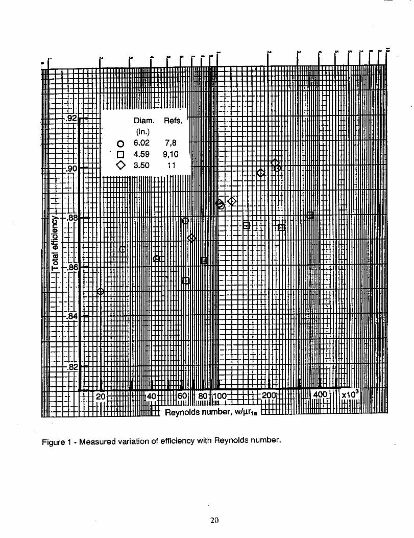
Performance measurements for three radial-inflow turbines, which are scaled versions of
the same design having 6.02-, 4.59-, and 3.50-inch rotor-tip diameters, over ranges of
Reynolds number are presented in references 7-1 1. The three turbines had the same design
velocity diagrams, with variations in design pressure and rotative speed accounting for the
different sizes. The Reynolds number variation for each turbine was achieved by testing over
a range of inlet pressures. These turbines are used only to determine Reynolds number
7
dependency because they are off-the-shelf industrial turbocharger hardware and, therefore,do not represent aerospace design technology. Plotted in figure 1 against Reynolds number
are points representing efficiency at design speed and design pressure ratio for the threeturbines. These points were obtained from smoothed curves through experimental points of
efficiency plotted against pressure ratio.
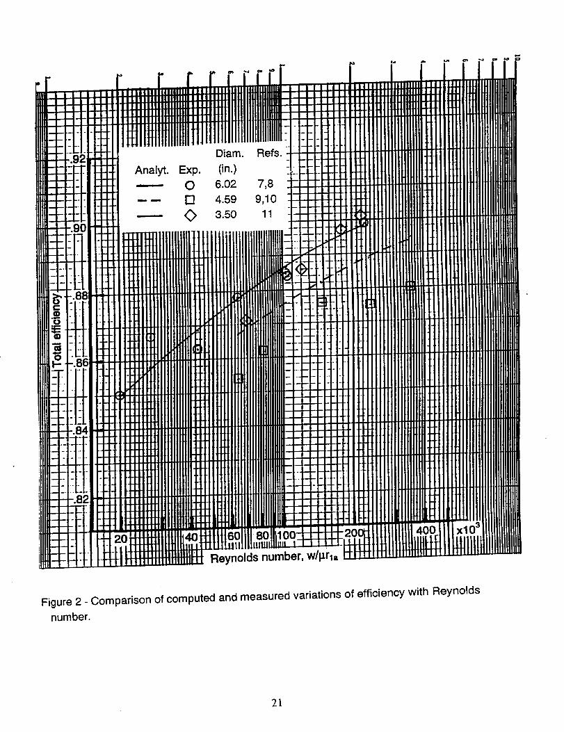
Within the experimental variability noted in figure 1, the Reynolds number dependency forthe three turbines can be considered the same. Using the type of function
Loss = KRe + (1 - KRe) Re"'2 (17)
for the stator and rotor passage losses as was used in references 7 and 9 for overall loss, avalue of KRe==0.3 produces the desired variation of efficiency with Reynolds number, as
shown by the curves in figure 2. The level of turbine efficiency is determined by the statorand rotor reference loss coefficients, which for the purposes of figure 2 were arbitrarily set tomatch the efficiencies of the 6.02- and 3.50-inch diameter turbines. The efficiencies for the4.59-inch diameter turbine were lower than those for the other two turbines by about two
points, about half of which is accounted for by the loss model due to a larger rotor-exitclearance.
Efficiency Level
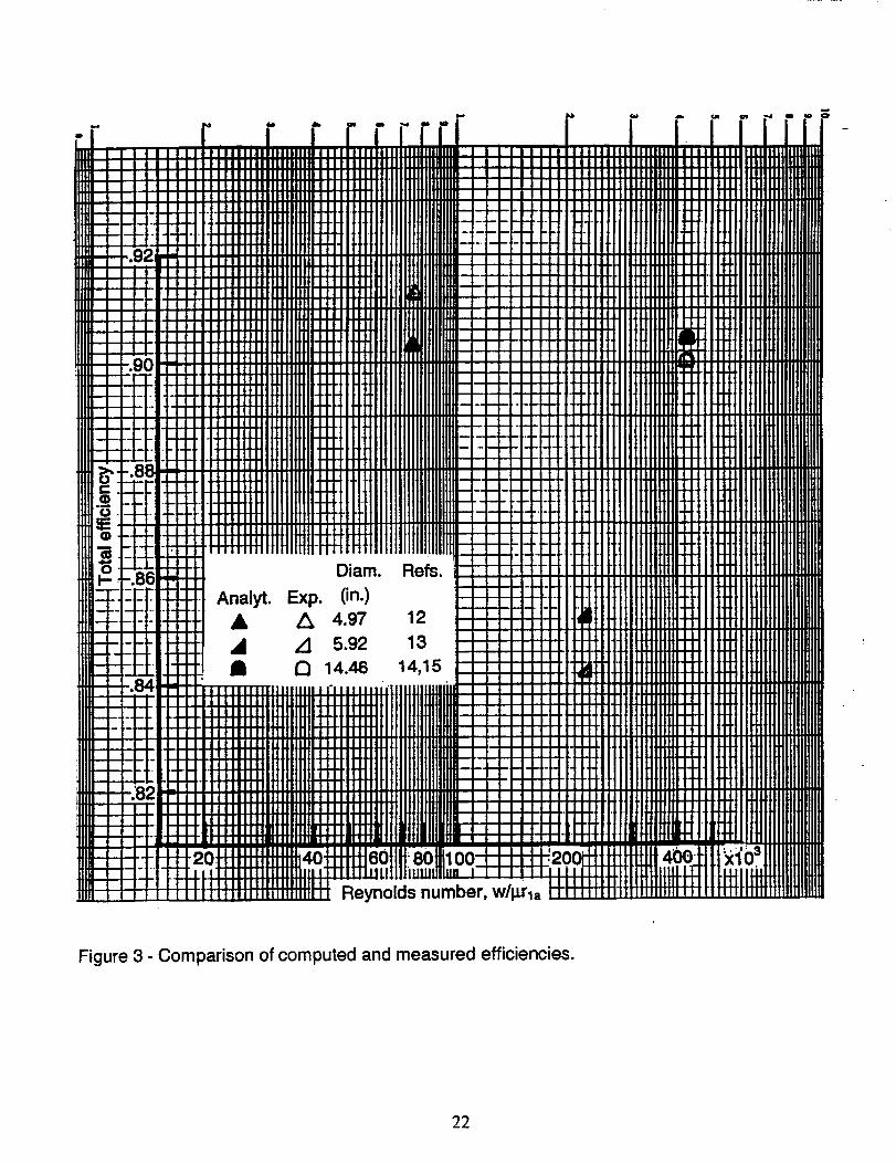
The geometries and experimental performances for three other radial-inflow turbines attheir design Reynolds numbers (see table I for design characteristics) are presented in refer-ences 12-15. These turbines were specifically designed for their intended applications using
aerospace design technology and, therefore, should provide the best achievable
performance.
The 5.92- and 14.46-inch diameter turbines were designed for "off-design" conditions with
Ioadings higher than optimum and, therefore, efficiencies less than maximum. Since thiscomputer code produces optimum designs, the measured "design-point" efficiencies needcorrection for proper comparison. For the 5.92-inch diameter turbine (ref. 13), whereextensive data is presented, the maximum efficiency on the design speed line is used. In thecase of the 14.46-inch diameter turbine (refs. 14 and 15), where the data is not as definitive,
the incidence loss determined by the analysis in reference 16 is added to the measured
design-point efficiency. In both cases, the efficiency is 1.5 points higher than the measured
design-point value.
The stator and rotor reference loss coefficients (used in eqn. (7) of ref. 1) selected to bestfit the data are
(6to t / I )ref,s " 0.0023119 (18)
and
(0tot / I )ref,r= 0.0066267 ( 19 )
The ratio of values is somewhat arbitrary, reflecting the higher loading and diffusion in therotor. Detailed measurements and/or analysis are required for better definition.
Using these values of reference loss coefficients, the computed efficiencies are comparedto the measured values in figure 3 for the three turbines. The maximum deviation is about
one point. The 5.92-inch diameter turbine was purposely designed with very thick stator androtor trailing edges, to simulate cooled blading, as well as a relatively long vaneless space,
and these features are reflected in the lower efficiency of this turbine.
DESCRIPTION OF INPUT AND OUTPUT
This section presents a complete description of the input and output for code RTD. Theinput and corresponding output for two sample cases are included for illustration. There are
several error messages indicating the nonexistence of a solution satisfying the specifiedinput requirements. These messages are self explanatory and, usually, reflect input error.
Input
The program input, which is read on unit 05, consists of a title line and one NAMELISTdataset. The title, which is printed as a heading on the output, can contain up to 79characters located anywhere in columns 2 through 80 on the title line. A title line, even if it is
left blank, must be the first line for each case. The data are input in data records having theNAMELIST name INPUT. The variables that compose INPUT are defined below along withunits and default values. Either SI units or U.S. customary units may be used with this
program.
A sample input file containing two cases is shown in table I1. Each case is headed by atitle line. The first case is for the turbine of reference 12, which was tested with argon. Thisturbine was designed for optimum rotor incidence. The second case, which is an air turbine,
is for an optimum design corresponding to the design requirements of reference 13.
ALPHA0 stator-inlet flow angle from radial direction, deg
(input only when NSTAR = 0 or 1)
ALPHAll stator-exit blade angle from radial direction, deg
BETAB rotor blade inlet angle, deg (backsweep is positive - default=0.0)
CDT2 ratio of clearance to rotor-exit tip diameter (default=0.0)
CFU1A multiplier for optimum tangential velocity at rotor inlet (default=1.0)
CLFR1 ratio of stator clearance to stator passage height (default=O.O)
CR
CS
EBARR
EBARS
GAM
INRBL
INSTV
IOFF
ISP
IU
K
MU
N
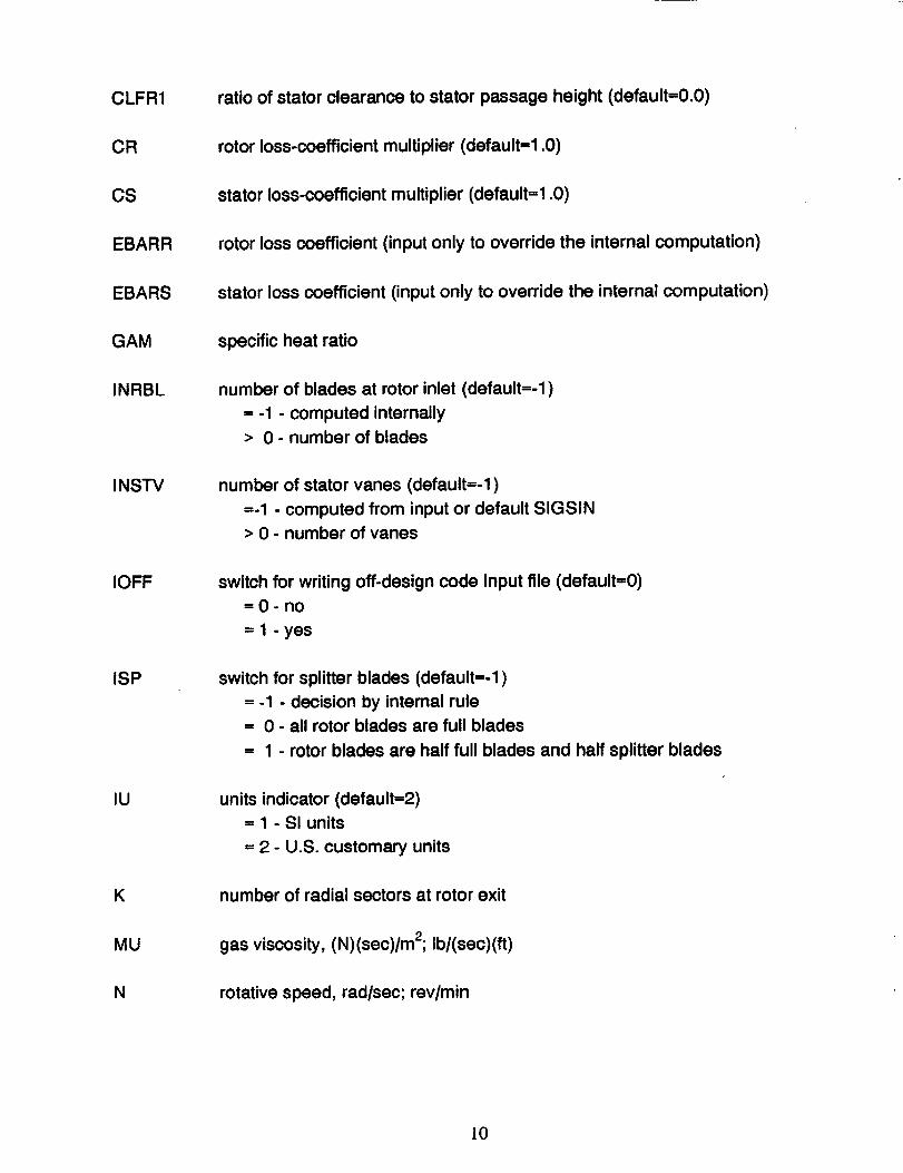
rotor loss-coefficient multiplier (default=1.0)
stator loss-coefficient multiplier (default=1.0)
rotor loss coefficient (input only to override the internal computation)
stator loss coefficient (input only to override the internal computation)
specific heat ratio
number of blades at rotor inlet (default=-1)
= -1 - computed internally
> 0 - number of blades
number of stator vanes (default=-1)
=-1 - computed from input or default SIGSIN
> 0 - number of vanes
switch for writing off-design code input file (default=O)
=O-no
= 1 - yes
switch for splitter blades (default=-1)
= -1 - decision by intemal rule
= 0 - all rotor blades are full blades
= 1 - rotor blades are half full blades and half splitter blades
units indicator (default=2)= 1 - SI units
= 2 - U.S. customary units
number of radial sectors at rotor exit
gas viscosity, (N)(sec)/m2; Ib/(sec)(ft)
rotative speed, rad/sec; rev/min
lO
NSTAR
POW
PTIN
R
RBFR1A
RH2RT2
RT2R1A
RV1AAV
RV212M(I)
I=I,K
ROR1A
RIR1A
SIGSIN
STAR
TOH1
TOH2M
TTIN
W
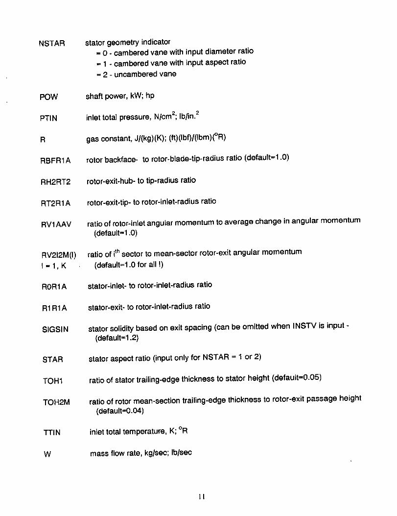
stator geometry indicator
= 0 - cambered vane with input diameter ratio
= 1 - cambered vane with input aspect ratio
= 2 - uncambered vane
shaft power, kW; hp
inlet total pressure, N/cm2; Ib/in. 2
gas constant, J/(kg)(K); (ft)(Ibf)/(Ibm)(°R)
rotor backface- to rotor-blade-tip-radius ratio (default=1.0)
rotor-exit-hub- to tip-radius ratio
rotor-exit-tip- to rotor-inlet-radius ratio
ratio of rotor-inlet angular momentum to average change in angular momentum
(default=1.0)
ratio of ith sector to mean-sector rotor-exit angular momentum
(default=1.0 for all I)
stator-inlet- to rotor-inlet-radius ratio
stator-exit- to rotor-inlet-radius ratio
stator solidity based on exit spacing (can be omitted when INS'IV is input -
(default=1.2)
stator aspect ratio (input only for NSTAR = 1 or 2)
ratio of stator trailing-edge thickness to stator height (default=O.05)
ratio of rotor mean-section trailing-edge thickness to rotor-exit passage height
(default=O.04)
inlet total temperature, K; °R
mass flow rate, kg/sec; Ib/sec
I1
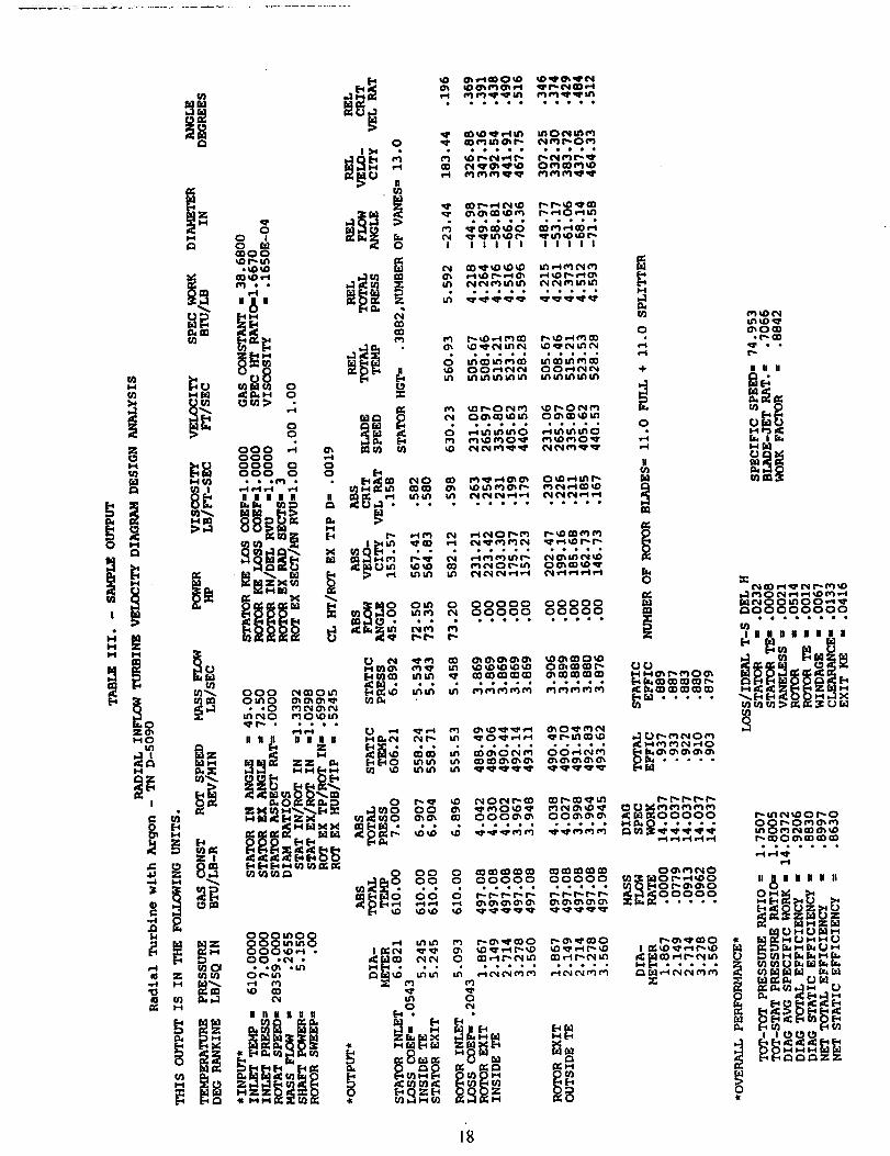
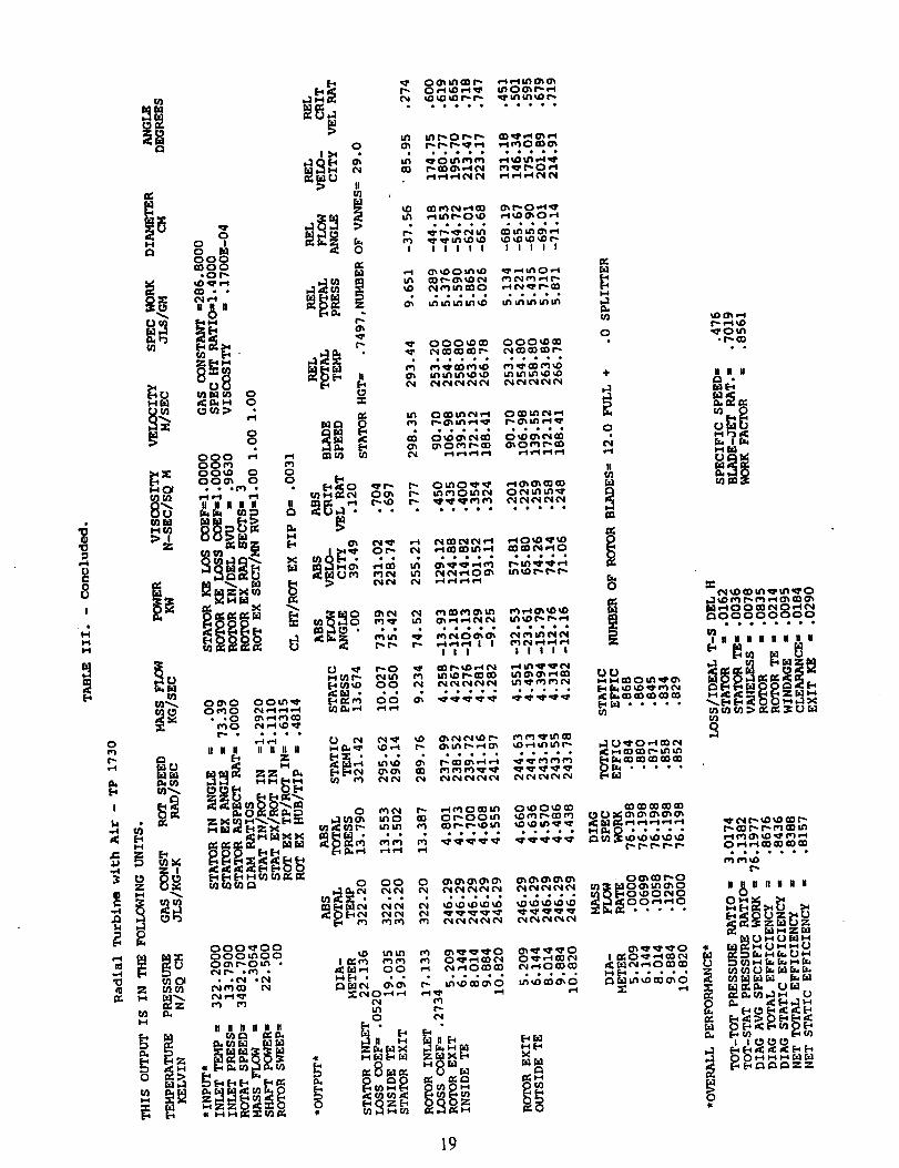
Output
The program output consists of title headings, the input values, and the computed results.Table III presents the output that corresponds to the sample input shown in table I1. The top
line of output is a program identification title that is printed with the first case of each data file.The second line is the case title from the input title line. The next three lines show the unitsused for the different variables.
The heading *INPUT* is followed by the input values used for this case. Identification of
the items is self-explanatory. The zero value shown for stator aspect ratio indicates that thiswas not an input for this case. Values of 1.0000 are shown for the stator and rotor losscoefficients to indicate that the actual values are computed using the internal loss model.
The heading *OUTPUT* is followed by the computed results. Temperatures, pressures,flow angles, velocities, and velocity ratios, along with diameter, are shown for each
calculation station, which are stator inlet, stator exit inside trailing edge, stator exit outsidetrailing edge, rotor inlet, rotor exit inside trailing edge, and rotor exit outside trailing edge. Atthe rotor exit, the computed values are shown at the mean diameter of each sector as wellas for the hub and the tip. Additional output for the rotor-exit sectors include flow rate,specific work, and total and static efficiencies. Also shown are the computed loss coefficientsfor the stator and rotor, the stator height, number of stator vanes, and number of rotor blades,
both full and splitter.
Under the heading *OVERALL PERFORMANCE* are the turbine total-to-total and total-to-static pressure ratios, diagram specific work, and both diagram and net total and staticefficiencies. Also shown are the individual loss components as fractions of the turbine idealwork, the specific speed, the blade-jet speed ratio, and the work factor.
The first case uses U.S. customary units while the second case uses SI units. Since the4.97-inch diameter turbine of reference 12 was an optimum design, the rotor tip diameter
computed for the first case should be close to the actual value; and it is, differing only by 2.5percent (5.093 inches). For the second case, the computed optimum diameter (17.13 cm.)was 14 percent higher than the diameter (15.04 cm.) of the reference 13 turbine, which had
been designed for a higher than optimum loading.
SUMMARY OF RESULTS
This report presents modifications made to a radial-inflow turbine conceptual design code,herein named RTD. The analysis is based on meanline flow through the stator and into therotor, and on equal span-fraction sectors at the rotor exit. Input design variables include flow,power, and rotative speed. The output presents rotor-tip diameter, flowpath dimensions,diagram velocities and angles, and efficiencies. Design parameters that can be variedinclude stator-exit angle, rotor-exit tip and hub radius ratios, and rotor swirl distribution.
Modifications were made to enhance the design-code capabilities consistent with those of
12
a companion off-design code. To accommodate pivoting vanes, stator-endwall clearanceeffects were modeled by a vaneless-space flow through the clearance height, and this clear-
ance flow was then mixed with the passage flow just beyond the stator trailing edge. Therotor-inlet slip model and the rotor.blade-number calculation were changed to allow
rotor-blade-inlet angles other than radial, thus permitting the use of swept rotor blades. Forradial blades, the computed slip and blade number were very close to those from the
previous models. In addition, splitter blades between the full blades can now be optionallyspecified.
Added to the loss model were stator and rotor trailing-edge blockage losses and avaneless-space loss. The trailing-edge losses are reductions in kinetic energy that depend
on the fraction of flow area that is blocked. The vaneless-space loss is computed as a frictionloss for flow between the parallel endwalls. A change was made to the disk-friction loss toaccount for backfaces that do not fully extend to the rotor tip. The rotor-clearance loss was
changed to reflect the non-linear variation of loss with clearance height.
The variation of turbine efficiency with Reynolds number and the level of efficiency weredefined by calibrating the stator and rotor passage losses using experimental performancedata from six radial-inflow turbines. The selected model performed very well in predicting theturbine efficiency variation for three industrial turbines over a more than tenfold range of
Reynolds number. The efficiencies predicted for three aerospace turbines had a maximumdeviation of one point as compared to the measured values.
This report also serves as an updated users manual for the RTD code. Program input and
output are described, and sample cases are included for illustration.
REFERENCES
1. Glassman, A.J.: Computer Program for Design Analysis of Radial-Inflow Turbines. NASATN D-8164, 1976.
2. Meitner, P.L.; and Glassman, A.J.: Computer Code for Off-Design Performance Analysisof Radial-Inflow Turbines With Rotor Blade Sweep. NASA TP 2199, 1983.
3. Wiesner, F.J.: A Review of Slip Factors in centrifugal Impellers. J. Eng. Power, vol. 89,no. 4, Oct. 1967, pp. 558-572.
4. Katsanis, T.: Channel Flow Analysis. Ch. 5 of Turbine Design and Application, vol. 2,
A.J. Glassman, ed., NASA SP-290, 1973, pp. 27-56.
5. Stanitz, J.D.; and Prian, V.D.: Rapid Approximate Method for Determining VelocityDistribution on Impeller Blades. NACA TN 2421,1951.
13
6. Futral, S.M., Jr.; and Holeski, D.E.: Experimental Results of Varying the Blade-ShroudClearance in a 6.02-Inch Radial-Inflow Turbine. NASA TN D-5513, 1970.
7. Kofskey, M.G.; and Holeski, D.E.: Cold Performance Evaluation of a 6.02-Inch RadialInflow Turbine Designed for a 10-Kilowatt Shaft Output Brayton Cycle Space Power
Generation System. NASA TN D-2987, 1966.
8. Holeski, D.E.; and Futral, S.M., Jr.: Experimental Performance Evaluation of a 6.02-Inch
Radial-Inflow Turbine Over a Range of Reynolds Number. NASA TN D-3824, 1967.
9. Wasserbauer, C.A.; Kofskey, M.G.: and Nusbaum, W.J.: Cold Performance Evaluation of
a 4.59-Inch Radial Inflow Turbine Designed for a Brayton-Cycle Space Power System.
NASA TN D-3260, 1966.
10. Nusbaum, W.J.; and Wasserbauer, C.A.: Experimental Performance Evaluation of a
4.59-Inch radial-Inflow Turbine Over a Range of Reynolds Number. NASA TN D-3835,1967.
11. Kofskey, M.G.; and Wasserbauer, C.A.: Experimental Evaluation of a 3.50-Inch Radial
Turbine Designed for a 10-Kilowatt Space Power System. NASA TN D-5550, 1969.
12. Nusbaum, W.J.; and Kofskey, M.G.: Cold Performance Evaluation of 4.97-Inch
Radial-Inflow Turbine Designed for Single-Shaft Brayton Cycle Space-Power System.
NASA TN D.5090, 1969.
13. McLallin, K.L.; and Haas, J.E.: Experimental Performance and Analysis of
15.04-Centimeter-Tip-Diameter, Radial-Inflow Turbine With Work Factor of 1.126 and
Thick Blading. NASA TP 1730, 1980.
14. Fredmonski, A.J.; Huber, F.W.; Roelke, R.J.; and Simonyi, S.: Design and Experimental
Evaluation of Compact Radial-Inflow Turbines. AIAA Paper 91-2127, 1991.
15. Simonyi, P.S.; Roelke, R.J.; Stabe, R.G.; Nowlin, B.C.; and DiCicco, D.: Aerodynamic
Evaluation of Two Compact Radial-Inflow Turbine Rotors. NASA Report, In progress.
16. Simonyi. P.S.; and Boyle, R.J.: Comparison of a Quasi-3D Analysis and Experimental
Performance for Three Compact Radial Turbines. AIAA-91-2128, 1991.
14
Appendix
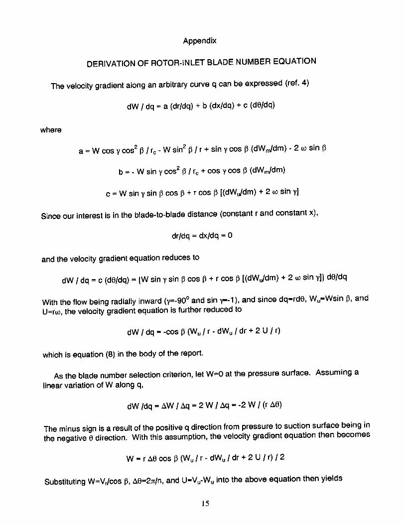
DERIVATION OF ROTOR-INLET BLADE NUMBER EQUATION
The velocity gradient along an arbitrary curve q can be expressed (ref. 4)
dW / dq = a (dr/dq) + b (dx/dq) + c (di)/dq)
where
a = W cos _' cos 213 / rc - W sin 2 I] / r + sin y cos I_ (dWm/dm) - 2 u_ sin (_
b = - W sin y cos 2 0 / rc + cos y cos l_ (dWm/dm)
c = W sin y sin 13cos 13+ r cos 13[(dWu/dm) + 2 _ sin y]
Since our interest is in the blade-to-blade distance (constant r and constant x),
drldq = dxldq = 0
and the velocity gradient equation reduces to
dW / dq = c (de/dq) = {W sin 't sin 13cos I] + r cos i_ [(dWu/dm) + 2 to sin y]} de/dq
With the flow being radially inward (7=-90 ° and sin 7=-1 ), and since dq=rd0, Wu=Wsin I% and
U=r_0, the velocity gradient equation is further reduced to
dW / dq = -cos 13(Wu / r - dWu / dr + 2 U / r)
which is equation (8) in the body of the report.
As the blade number selection criterion, let W=O at the pressure surface. Assuming a
linear variation of W along q,
dW/dq = &W / &q = 2 W / z_q = -2 W / (r &e)
The minus sign is a result of the positive q direction from pressure to suction surface being in
the negative 0 direction. With this assumption, the velocity gradient equation then becomes
W = r40 cos 13(Wu/r- dWu Idr + 2 U / r)/2
Substituting W=VJcos 13,&O=2=/n, and U=Vu-Wu into the above equation then yields
]5
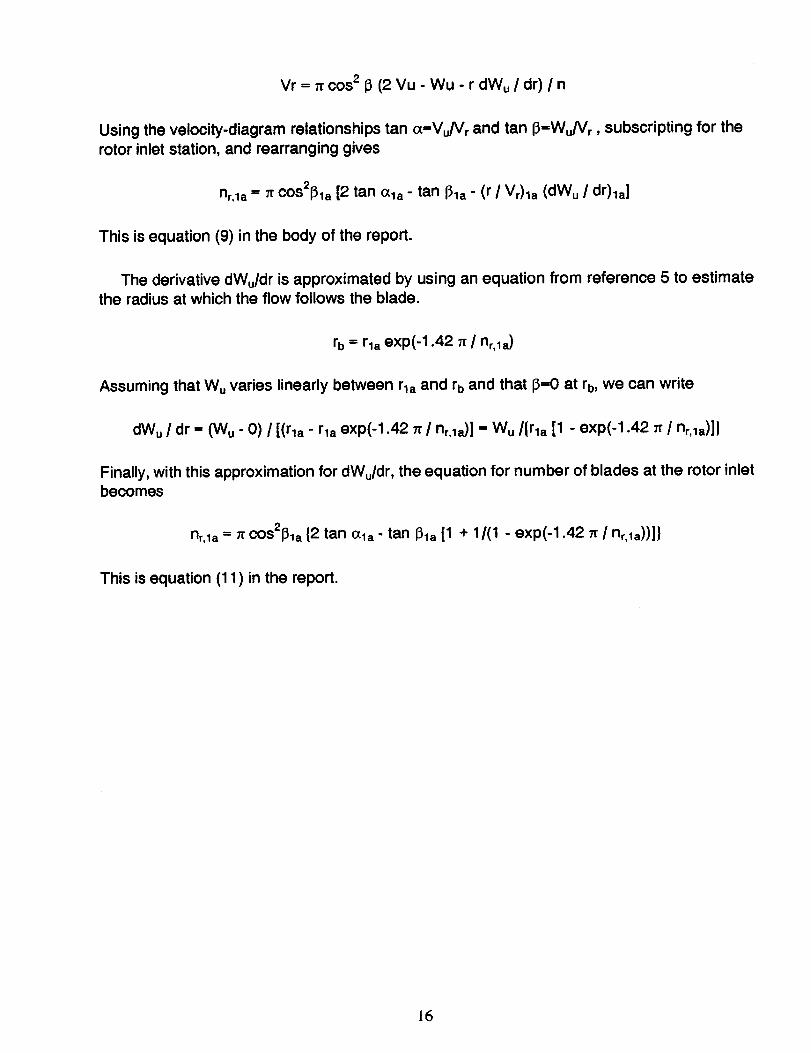
Vr = n cos 2 13(2 Vu - Wu - r dWu / dr) / n
Using the velocity-diagram relationships tan (x=Vu/Vr and tan 13=Wu/Vr, subscripting for the
rotor inlet station, and rearranging gives
nr,la = 71"COS2f_la [2 tan O.la - tan 131a- (r / Vr)la (dW u / dr)la]
This is equation (9) in the body of the report.
The derivative dWu/dr is approximated by using an equation from reference 5 to estimate
the radius at which the flow follows the blade.
rb = rla exp(-1.42 7r / nr, la )
Assuming that Wu varies linearly between rla and rb and that 13=0 at rb, we can write
dWu / dr = (Wu- 0) / [(rla - rla exp(-1.42 n / nr,la)] = Wu/{rla [1 - exp(-1.42 tr / nr,la)]}
Finally, with this approximation for dWu/dr, the equation for number of blades at the rotor inletbecomes
nr,la = Trcos2pla {2 tan ala- tan Pla [1 + 1/(1 - exp(-1.42 _ / nr, la))]}
This is equation (11 ) in the report.
16
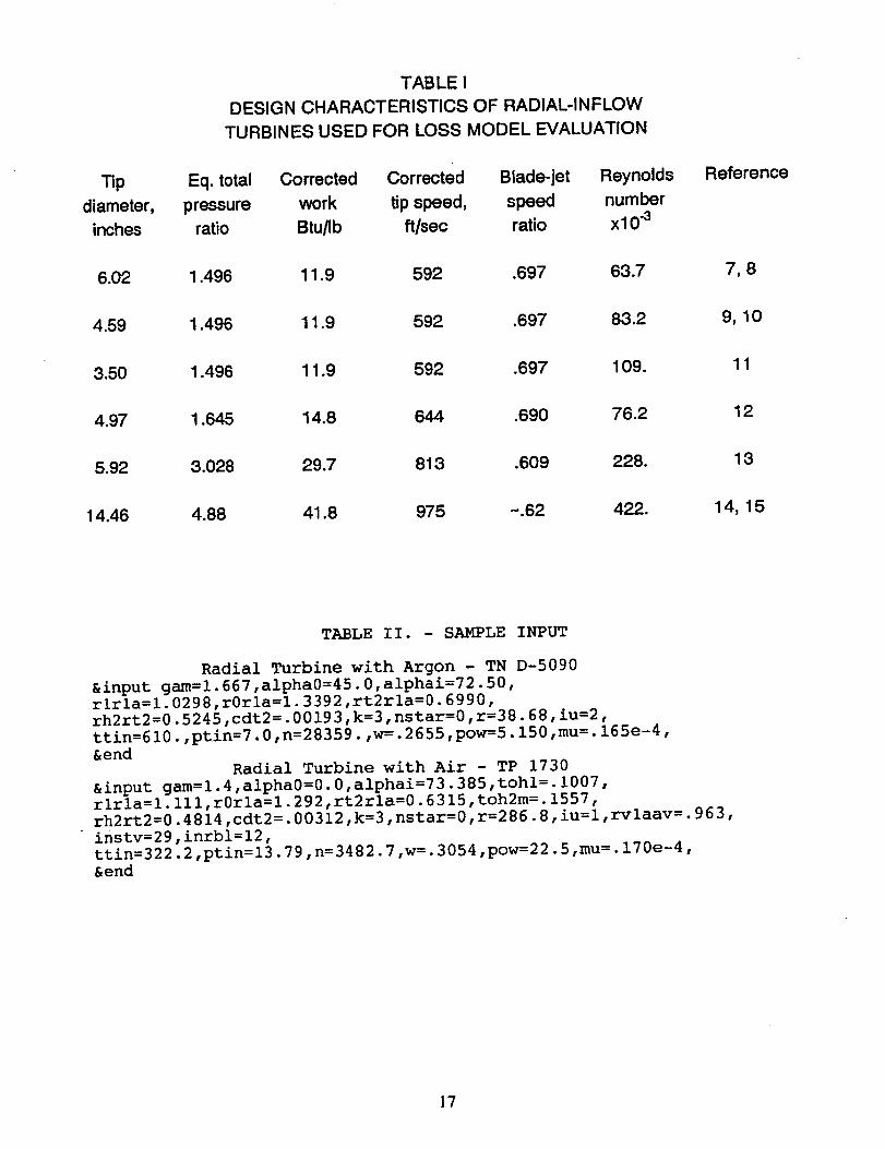
TABLE I
DESIGN CHARACTERISTICS OF RADIAL-INFLOW
TURBINES USED FOR LOSS MODEL EVALUATION
Tip Eq. total Corrected Corrected Blade-jet Reynolds
diameter, pressure work tip speed, speed number
inches ratio Btu/Ib ft/sec ratio xl 0 .3
Reference
6.02 1.496 11.9 592 .697 63.7 7, 8
4.59 1.496 11.9 592 .697 83.2 9, 10
3.50 1.496 11.9 592 .697 109. 11
4.97 1.645 14.8 644 .690 76.2 12
5,92 3.028 29.7 813 .609 228. 13
14.46 4.88 41.8 975 -.62 422. 14, 15
TABLE II. - SAMPLE INPUT
Radial Turbine with Argon - TN D-5090
&input gam=l.667,alpha0=45.0,alphai=72.50,
rlrla=l.0298,r0rla=l.3392,rt2rla=0.6990,
rh2rt2=0.5245,cdt2=.00193,k=3,nstar=0,r=38.68,iu=2,
ttin=610.,ptin=7.0,n=28359.,w=.2655,pow=5.150,mu=.165e-4,&end
Radial Turbine with Air - TP 1730
&input gam=l.4,alpha0=0.0,alphai=73.385,tohl=.1007,
rlrla=l.lll,r0rla=l.292,rt2rla=0.6315,toh2m=.1557,
rh2rt2=0.4814,cdt2=.00312,k=3,nstar=0,r=286.8,iu=l,rvlaav=.963,
instv=29,inrbl=12,
ttin=322.2,ptin=13.79,n=3482.7,w=.3054,pow=22.5,mu=.170e-4,&end
17
I>4 •
N
M 0 I
_00
• eeloe oeee0
• 0eo_e eooe0
_ 0_
I IIIII IIIII
__ .....
_eee_ ,eeee
1"4
U3
0
+
ooo _000
ooooo.o.o.,,_. °°. _0_ _o ® _,_o,_, o_o_,-II II l N H ("4¢'_1¢'_1o,-_-o c_1¢"_1¢'_1,,-q,,"1
_1 _1_0 Om 0 00000 00000_0_10 U_r'_ _ 00000 00000
Ou_O ¢_h _ "
I W It tt no | B _-4_ _r_
_z_ _ zz _ _o _
oOOmO0ooom_o000_,00,_.°°_o_
!!
__0_
II
__ _0__0_ _ __0_
_ _ __ __ ° • ° ° °
000_ 00_ <_00000
....... _o_o_oq°°°° °°R°q _ooooo
I _ _ _ __ __
_mm<
0_0_).p.-_
II II II.
_00_00__00000000
ee_eeeoe
IilUIIIll
l_lflllll
_M_M
,,__
18
'O
m,4OK:
8I
,4Hl,=#
O
w-4
I
.,,-I
.,.,4
@
M
...i
0
_ _ _ o_ _O_
_ ...........
u
0 _ _ 0 I lllll IIIII000
_= ...........
• _ mom_m mom_m _ _ _
_ __oo_o o_ _ _" _lIlll fl
_. • .,., ...._ _ _0_ __ _ ° ° ° .
_U
_,8_
_5tnO_
_o ,ee.
_ 0 O0 0 _ _ 0_0
......... _o=o_o
0oo_oo
• ,_ *_ _ • • • • , .... . • . • • _ • • • • ,
0
i! °"4I
o__
N_HHNHNO_
_OUZ_O
_ __U_
19
0 6.02
_ 4.593.50 11
Reynolds number, w/IJ.rl.
Figure 1 - Measured variation of efficiency with Reynolds number.
2O
Analyt. Exp.
Reynolds number, W/llrla
Figure 2 - Comparison of computed and measured variations of efficiency with Reynolds
number.
21
Analyt. Exp. (in.)
i
I
I
I
I
I
I
Reynolds number, w/iJ.rla
Figure 3 - Comparison of computed and measured efficiencies.
22
Form ApprovedREPORT DOCUMENTATION PAGE OMBNo. 0704-0188
PublicrepottingburdenIorthiscoll,=ctionof intocmat_onis estimatedto average 1 hourper response,includingthe time forreviewinginslruction$, searching exislin 9 0wasources,gatheringandmainlainin_lthe dataneeded,andcomplelingandreviewing1hecollectionof information.Sendcommentsregardingthis burdenestimateor anyotheraspectof thiscollectionof information,includingsugga,=tionsforreducingthis burden,lo WashingtonHeadquartersServices.DirectorateforInlormalionC_erat_nsandReports,1215JeltarsonDavisHighway,Suite1204,Arlington,VA 22202-4302,andto theOfficeof ManagementandBudget,PaperworkReductionProjecl(0704-0188).Washington,DC 20503.
1. AGENCY USE ONLY (Leave blank) 2. REPORT DATE 3. REPORT TYPE AND DATES COVERED
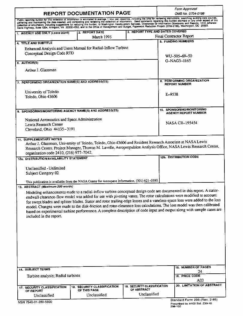
March 1995 Final Contractor Report4. TITLE AND SUBTITLE S. FUNDING NUMBERS
Enhanced Analysis and Users Manual for Radial-Inflow TurbineConceptual Design Code RTD
6. AUTHOR(S)
Arthur J. Glassman
7. PERFORMING ORGANIZATION NAME(S) AND ADDRESS(ES)
University of ToledoToledo, Ohio 43606
9. SPONSORING/MONITORING AGENCY NAME(S) AND ADDRESS(ES)
National Aeronautics and Space AdministrationLewis Research Center
Cleveland, Ohio 44135 - 3191
WU-505--69-50G-NAG3-1165
8. PERFORMING ORGANIZATIONREPORT NUMBER
E-9538
10. SPONSORING/MONITORINGAGENCY REPORT NUMBER
NASA CR-195454
11. SUPPLEMENTARY NOTES
Arthur I. Glassman, University of Toledo, Toledo, Ohio 43606 and Resident Research Associate at NASA LewisResearch Center. Project Manager, Thomas M. Lavelle, Aeropropulsion Analysis Office, NASA Lewis Research Center,organization code 2410, (216) 977-7042.
12a. DISTRIBUTION/AVAILABILITY STATEMENT
Unclassified - Unlimited
Subject Category 02
This publication is available from the NASA Center for Aerospace Informauon, (301) 621--0390.
12b. DISTRIBUTION CODE
13. ABSTRACT (Maximum 200 words)
Modeling enhancements made to a radial-inflow turbine conceptual design code are documented in this report. A stator-endwall clearance-flow model was added for use with pivoting vanes. The rotor calculations were modified to account
for swept blades and splitter blades. Stator and rotor trailing-edge losses and a vaneless-space loss were added to the lossmodel. Changes were made to the disk-friction and rotor-clearance loss calculations. The loss model was then calibratedbased on experimental turbine performance. A complete description of code input and output along with sample cases areincluded in the report.
14. "SUBJECT TERMS
Turbine analysis; Radial turbines
17. SECURITY CLASSIFICATIONOF REPORT
Unclassified
18. SECURITY CLASSIFICATIONOF THIS PAGE
Unclassified
NSN 7540-01-280-5500
19. SECURITY CLASSIFICATIONOF ABSTRACT
Unclassified
15. NUMBER OF PAGES
2416. PRICE CODE
A0320. LIMITATION OF ABSTRACT
Standard Form 298 (Rev. 2-89)Prescribed byANSI Std. Z3_-18298-102

Recommended