7/23/2019 Engineering Vol 72 1901-11-29
http://slidepdf.com/reader/full/engineering-vol-72-1901-11-29 1/31
•
Nov.
29, 1901.]
E N G I N E E R I N G.
73
s z · t s a a
QTFGC
:
•
•
a m
lVIACHINE TOOLS AT THE
STANLEY SHOW.
and
other tools.
But the objects
of grea.test are
pr
oceedin g
i m u l t a n e
on fo
ur d i f f e r ~ ~ t
in
terest
are t
hree
Acme four-spindle automatic pieces, and when the fourth IS completed, t ~ e
thud
h
.
th latest de
vel
opment
in this is also accomplished
on the
ne
xt one behind, the
THO
UG
H machine tools are not
nume
rous this
year
at
t
he Stanl
ey
Sh
ow,
the ir in t
e
rest
makes up for lack
of number. No English tools of impor tance are
to
be
seen ; but we have the four-spindle Acme screw
machine a recent tool which pr omises
to hi
t the
ordinary tu rret l
at
hes hard,
and
we also have some
screw mac tnes, e d th fi t · e has passed
class of tool, illust rated by
Fig.
f on page 734, seco
nd
O t
he
next, an e rs ptec
and by deta
iled fig
ur
es on th
at
page
and
page 735. th rough I
ts
first stage. .
I t marks what will probably prove
to
be a most At each m p l ~ t e
r e v o l ~ 1 0 n
or
cycle of the
four
important d
epartu
re
in
screw-machin e design- the
I
wo
rk
-holdtng s
pindl
es a p t e c ~ IS
completed c ~ t
substitu
t ion of several w
or
k spindles for one, so
off
while t he
other three spindles carry
1
multiplying the output of a single
ma
c
hin
e.
And
I uccessive stages of progress.
Of
course, 1n the
•
•
•
•
FIG. 25
.
RELIEV
I
NG
LA
l HE,
BY M E
SS
RS. J. E.
REINE
CKER, CHEl\INITZ-GABLENZ .
•
•
•
•
F IG. 26 . ·
TaE
BILGRlli BE V
EL-GEa
R OuTTING MACHINE .
fine examples of the Reh lecker machines, th
at
are it has passed the
exper
ime
ntal
stage, be
ing in
seco
nd
to none
of German man ufacture. Messrs. successful use
in
many
works.
Schischkar
and Co
. are exhibiting the first a
nd The
idea which unde
rli
es the design is t
hi
s : that
Messrs.
Pfeil and Co
. t
he
second ,
both si t
uated
at
in
stead
of a single bar being o
perated
u
po
n
at
one
the lower end of the Agricultural
Hall
n the time by a successi
on
of tools held in a t
ur ret
, fo
ur
ground
fl
oo r. ba
rs are being
cut and sha
ped
simultaneously
by
We
commence at the stand of
Me
ssrs. Sc
hi
schkar four separa
te
too
ls or
groups
of tools in the main
and Co .,
whose bnsiness premises are located
at
tool-carrier. Supposing
now that four
successive
65 to
69, Stafford-street,
Birmingham.
I t com-
cutting operat
io
ns are
necessa
ry
to com
plete a
prises good collection of Ja.thefl drilljng mac
hin
es, piece of
wo
rk the first. second, thi rd, and four th
-
•
•
FIG
24. E IGHT-SPINDLE D
RILL,
BY ME SSRS
Scn r
sc
HKAR AND
Co.
case of some
plain
pi
eces
this re
sult is duplicated
in one cycle. I t follows the
ref
ore
that
the
long
est
single
operation
go
vern
s the
sp
eed of
the
work.
f this
is h
aste
ned to the m
aximum
pr acticable, the
ot
hers
can be
performed at
a
ny convenient
r
ates
,
even though they
should
be under those done in
o
rdinary
circumstances.
In
the common
accept
ance of t
he term
the ma.ch1ne is not a
turret lathe.
Yet in st
rictne
ss there are
two
turrets, of cy in
drical shape-one, which
carries
the
four work·
spindles; the other, in
alig
nment with
it
on
the
same
bed, carr ies t
he
tool-holders. The various
synchronous movemen ts of t
he
se two cylindrical
heads or turrets form an in tere
st ing
study
in
automatic
devices,
to
which we
can
ha
rdly
do
full
justice
in a
brief descripti
on.
L oo
king at
the
perspec t
ive view,
Fig. l,
the
general
arrangement is seen to comprise the work-spindle
carryin
g head, to the left, opposed
to
the tool-carry
ing
he
ad to
the
right
hand,
and three
supplemen
tary tool slides for cross-cutting, forinina, and k.nurl
ing.
All
these a
re driv
en from t he
p u l l ~ y to
the
ex·
t reme right, operating a shaft that passes through
both
heads
. The cam-shaft below,
actuat
ed by
gears
par tly seen in
front,
protected by a cas
ing
, carries
two
drums and
a disc. The drum t o
the
right
actuate
s the t ool-head,
that to the left the wire
feed and c
hucks
of the work -spindles, and a diso
about
the
centre
the two cross-slides
on
the be
d.
The tool-head or slide has bu t one
movemen
t for
each piece of
work
com
pleted,
and
therefore bu
t
o
ne
camplate is
re
quired, which simplifies the fixing
up,
and lessens th e wear
on the pin. Simple
tools,
or
box
tools,
as
on o
rdinary turret lathes, are em
ployed, so th
at
it is possible
to have
not
merely
•
7/23/2019 Engineering Vol 72 1901-11-29
http://slidepdf.com/reader/full/engineering-vol-72-1901-11-29 2/31
seven
tools-four on the tool-head
and three on
sl i les-but
seven
sets
of tools
if
necessary.
In the
various detailed figures the bed is
marked
A,
the spindle,
or
work-carrying,
turret B, and
the
main
tool-carrier C. All the mechanism
stands
over
an
oil tray.
To
understand the
method
of
operations
i t
is necessary
to
trace
out the
principal
portions
of the machine, beginning
with
the work
carrying turret.
E N G I N E E R I N G.
the
work-holding turret is
held
stationary.
The
relation betw
een the cutting and
return speeds is
about
four-fifths of a complete
rotation
of the cam
shaft
for
cutting,
and
about
one-fifth for the return
of the tools.
The details of the work-spindle
head
may now
be
con£>idered.
It
is clear
that
when four work-
spin
dle s
have
to be
maintained
in alignment
with four tool
spindles carrying single tools
or
sets of tools in a
sepa
ra te
head,
the
difficulties of securing
the
per
manent accuracy of each in service
are greater
than
in
the case of one-s{>indle lathes. The design of
the
Acme machine embodies
neat
provisions for
locking, and also fo1· effecting adjustments from
time
to
time, if such should
be found
necessary,
though we
are
informed that such adj u
stme
nts
are
practically
never
required. These
are
shown
in
Figs. 6 and 7, which
represent
the turret in two
positions :
that
in which it is locked (Fig. 6), as when
the
tools
are in
action,
and
that at the
intermediate
position while
it
is being
rotated
through a fourth
of a circle
by
the sector gear
d
(Fig. 7 .
On the cam- s
haft
J
there
is a disc N fitted with
cam-pieces which raise
the
lever 0 and draw back
the locking-pin u from its
notch
in the turret
cylinder, at which
instant the s t = ~ c t o r d
comes
into
action
and rotates the
cylinder.
During its
rota
tion the index-pin
xis
thrust back against
the
push
of
its spring by
the
pressure
of th e sloping side of
the notch against the end of the pin.
When
the
next
notch has
come round, the
lever
is released,
and
the pin is pulled into its
notch
by the action
of a coiled spring,
not
shown
in the
figure.
Instead
of a
notch into
which
the tapered end
of the locking-pin
'tll
would fit closely, a slight
l .. -- -
3
•
[Nov. 29, 1901.
vanced
by the
sleeve 5 havi
ng
a collared head 6
operated by the series of parallel levers S from
camd
on
the
cam-drum
R.
A screw
adjustment
in
the
upper
portion of these levers
permits
of making all
changes of feed
up
to
the
full range of
the
machine
without ever changing the cams. The overhang of
the
stock-bars is
supported
in
a
lantern
of tubes
which revolve through rollers
in
a circular guide.
We
have already mentioned that
the
work
spindles
are
not driven directly,
and
therefore
the
driving geaFs a (Figs. 4, 5, 11,
and
12) are
not
keyed directly on their spindles, but are connected
to a
spring
collet,
or
friction clutch, that encircles
the spindles P. The action of the clutch is auto
matic through
the
cam-drum below, so
that
a
spindle can
be rotated, or its
rotation be arrested
at
any
predetermined stage, a device which is
utilised
in
screwing.
There
is
no
reversal, and
therefore no crossed belts.
When
screw-thread
ing has to be performed on bar-work,
the
endlong
movement of
the bar
is
arrested by
disengaging
the friction clutch in connection with
the
driv
ing
pinion a (see the sectional view
in
Fig. 12).
The
recessed portion is
in
one with the pinion, and
both
are run loosely on a collar 7, which is secured
to the
sleeve
P. The inner
portion of
the
clutch
8 is keyed to
the
sleeve,
and
confines two curved
springs,
and
cam-levers which
abut
against
the
springs.
The other
portion of
the
clutch, keyed
to
the sleeve P, actuates the cam-levers which clutch
the loose and fast portions.
The
springs 10 bear
ing
against the disc 11, which is fixed to the sleeve,
drive
the
fast portion of
the
clutch
and the
disc as
one
by the
pressure
they
exercise on
the
levers
and
curved springs.
The
clutch
is
released automatic-
•
The cylindrical turret
or head
B (Figs. 2
and
3,
page 735), shown in detail in Figs. 4 to 7, has a bear
ing in a turret casing D
Fig.
8), which is fianged
and
bolted
to
the bed near the
left-hand
end
of
the
machine when viewed from
the
front. The
turret
carries
four
hollow spindles for
bar
work (see Figs.
11
12), each spindle being located at
the
same
radius
from the
centre,
and
equidistant
from its
fellows.
Each
is encircled with a
pinion
a (Figs. 4,
5, 11, and 12),
driven
simultaneously from a
central
wheel
b on
the
main
shaft E,
engaging with each.
The
shaft
E has
its
bearings
in
the work-spindle
turret
at one
end,
and in a bearing at
the other end
of
the
bed, and
is driven
by the belt pulley to the
right
hand, as
already
stated.
The
shaft
passes
through the centre of the main tool-carrier C. This
operating
mechanism
imparts rotation to the
work
spindle
head
of
an intermittent
character, to bring
the
spindles.
into line
with
the
tools, in which
positions
these are
locked while the spindles are
rotated
simultaneously. The direction of rotation
of
these
is backwards, or in the opposite direction
to that
of
lathe
spindles.
The
spindles
are not
driven direc t
ly,
but
through
a
clutch
mechanism,
in order that their
motion may
be arrested
auto
matically.
They
have no endlong movement,
but
the necessary advance is
imparted
to the main tool
carrier
C-slowly for cutting, with a quick return.
These movements are
actuated
by mechanism
through the
cam-shaft
J underneath the
ma
chine (Figs. 2, 4 5, 6,
and
7).
Fig.
6 is
taken
on
the
plane
z
y
of
the
casing, seen separately
in Fig.
8,
and
Fig. 7
through x
y
the
locking
pin
1t
and
the
index
pin x being in different planes. A
sector
gear
d is carried on the shaft
through
which
the
four
intermittent
movements
are
conveyed to
the cylindrical
head
B
by
means of th e engagement
of
d
with the spur gear
e cut
on
the outer end
of
the
head. The cam-shaft carries the drum
K,
upon
which cam
strips
(Fig. 2) are screwed to engage
with
a
pin
f
on the bottom of the tool-carrying
head
C. A worm-wheel
Lis
also keyed on the shaft,
and by this the shaft
J
is
driven
at
a slow speed
for
feeding,
and
a quick speed for withdrawal
I
r------- :l 1
-----
---
t
•
•
.• -
I
Fi. J.18 I
I
I Fig 20
l t · ..
_ . Fig.'21.
•
-.L ._
-
r----------
J.
fJ
18 .
lltt
•
11111
ill
•
-------- -----+1
, Ftf1.22.
I
•
...1
f
I
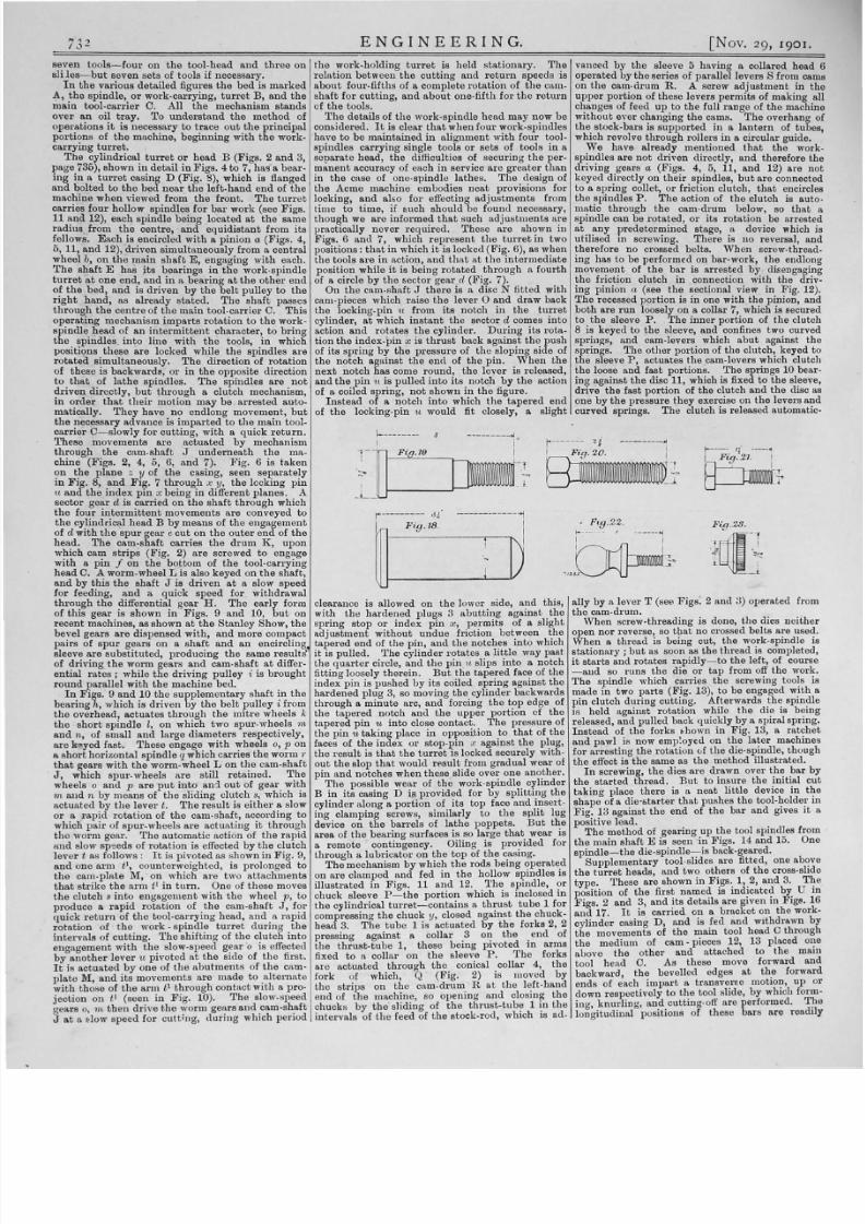
through
the differential gear H.
The early
form clearance is allowed on
the
lower side,
and
this,
of
this gear
is shown in
Figs
. 9 and 10, but on with the hardened plugs 3
abutting
against
the
recent
machines, as shown at the
Stanley
Show, the
spring stop
or
index pin
x, permits of a slight
bevel
gears are
di
spe
nsed
with, and more compact
adjustment
without
undue
friction between
the
pairs of
spur
gears
on
a
shaft and an
encirclin
tapered end
of
the
pin,
and the
notches into which
sleeve
are substituted, producing
the same
results
·
it
is pulled.
The
cylinder
rotates
a
little
way past
of driving the worm gears
and
cam-shaft at diffe
r-
t he q
uart
er circle,
and the pin
u slips
into
a notch
ential rates;
while the driving pulley
i is brought
fibting loose
ly
therein. But
the
tapered face of
the
round
parallel with the machine bed. index pin is pushed by its coiled spring against the
In Figs. 9 and
10
the supplem
enta
ry shaft in the hardened plug 3, so moving the cylinder backwards
bearing
h,
which is
driven
by the belt pulley i from through a minute arc, and forcing the top edge of
the
overhead, actuates
through the mitre
wheels
k the tapered
notch
and the upper
portion of
the
the
short
spindle
l,
on which two spur-wheels t
tapered pin 'tli
into close contact.
The
pressure of
and n, of small and large diameters respectively,
the pin 'tli
taking place in opposition
to
that of
the
are
y e d fast.
These
engage with wheels o,
p
on faces of the
index or
stop-pin x against
the
plug,
a short horizontal spindle qwhich ca
rries
the worm
r
the
result
is that the turret is locked securely with
that gears
with
the worm-wheel L on the cam-shaft out the slop that would
r t = ~ s u l t
from gradu al wear of
J,
which spur-wheels
are
still
retained.
The pin and
notches when these slide over one another.
wheels
o and p are
put
into and out
of gear with
The
possible wear of the work-spindle cylinder
m
and
n
by
n1eans of the sliding clutch
s
which is B in
its
casing D is provided for
by
splitting
the
actuated by
the lever
t.
The
re
s
ult
is
either
a slow cylinder along a portion of
its
top face
and in
sert
or a
rapid rotation
of the cam-shaft, according to
ing
clamping screws, similarly to the
split
lug
which pair of spur-wheels
are actuating
it t hrou
gh
device on the barrels of lathe poppets. But
t ~ e
the worm gear. The automatic ac tion of the rapid area of the bearing surfaces is so large
that
wear 18
and
slow
sp
eeds of
rotation
is effected
by the
c
lutch
a remote contingency. Oiling is provided for
lev er
t
as follows:
It
is pivoted
as
shown
in Fig. 9,
through a lubricator on
the top
of the casing.
and one arm
t
1
,
coun
te
rweighted, is prolonged to
The
mechanism
by
h i c ~
the
rods being
~ p e r a t e d
the cam-plate
M,
·
on
which
are
two
attachments
on
are
clamped and fed ID the hollow spmdles
IS
that strike the
a1·m t
1
in turn. One of
these
moves illustrated in
Figs.
11 and 12. l he spindle, or
the clutch s in to engagement with the wheel p, to chuck sleeve
P t h e
portion which is inclosed in
produce
a
rapid
rotation
of
the
cam-shaft J, for
the
cylindrical
turret-contains
a thrust
tube 1
for
quick return of the tool-carrying head,
and
o
rapid
compressing the chuck
y
closed aga
inst
the chuck-
.
rotation
of the work- spindle turret
during
the head 3.
The tube 1
is actuated by the forks 2, 2
intervals of cutting. The shifting of
the
clutch in to pressing ag ainst a collar 3
on the end
of
enaagement with
the slow-spe
ed
gear o is effected the t
hrust-tub
e 1, these being pivoted
in arms
by
0
another
lever
u pivoted at the side of the first. fixed to a collar on the sleev.e P. The forks
I t is actuated by
one
of the abutments of the cam- are actuated .through the. contcal . collar
4,
the
plate M, and
i
ts
movements
are
1nade to al
ternate
fork of which,
CJ
(
F1g.
2) 1s moved
by
with tho
se of
the arm
tl t
hr
ough contact with a pro-
the
st rips on the cam-drum. R at
the f t - h a n d
jection
on tl (seen in
Fig.
10). The slow-speed
end
of
the
m a c h ~ n ~ so openmg
and o s m ~ the
ge
ars
o, 1n then
drive
the worm gears and cam-shaft chucks
by
the
shdmg
of the
thrust-tub?
1 the
J at a ~ l o w s
peed for
cutting,
during
which period interva ls of the feed of the stock-rod, which IS
ad
-
ally by a lever T (see Figs. 2
and
3) operated from
the
cam-drum.
When screw-threading is done, the dies neither
open nor reverse, so
tbat
no crossed belts are used .
When
a thread is being cut,
the
work-spindle is
stationary ; but as soon as
the thread
is completed,
it starts
and rotates rapidly-to
the
left, of course
ud so
runs the
die
or tap
from off
the
work.
The
spindle which carries the screwing tools is
made
in
two
parts
(Fig. 13), to
be
engaged with a
pin clutch during cutting. Afterwards the spindle
is held against rotation while
the
die is being
released,
and
pulled back quickly by a
sp
iral spring.
Instead
of
the
forks t:hown
in
Fig. 13, a ratch
et
and
pawl is now e m p ~ o y e d on
the later
machines
for arresting the rotation uf the die-spindle, though
the effect is the same as the method illustrated.
In
screwing, the dies are drawn over
the
bar by
the started thread. But
to insure
the
initial
cut
taking place there
is
a
neat little
device
in the
shape of a die-starter that pushes tho tool-holder
in
Fig. 13
against the
end
of the
bar
a
nd
gives it a
positive lead.
The method of gearing up
the
tool spindles from
the
main
shaft
E
is
seen
in
Figs.
14
and
15.
One
spindle-the
die-spindle- is back-geared.
Supplementary tool-slides are fitted, one above
the
turret heads,
and
two others of
the
cross-slide
type. These are shown in F ~ g s 1, .2,
and
3. T ~ e
position of the
f i r s ~
1s
m d ~ c a t e ~
by_ U In
Figs. 2
and
3, and Its details are given m F1gs. 16
and 17. I t
is carried on a bracket on
the
work
cylinder casing
D, and
is .fed
and w i t h ~ r a w n
by
the
movements of
the mam
tool head C through
the medium of cam· pieces 12, 13 placed one
above the other
and attac
hed to the main
tool
head
C. As these move forward and
backward
the
bevelled edges
at
t
he
forward
.
ends of each
impart
a transverEe motwn, up or
down respectively to
the
tool slide, by which form
in
g, knurJing,
and
cutting-off are performed.
T ~ e
longitudinal positions of these bars
are
readtly
•

7/23/2019 Engineering Vol 72 1901-11-29
http://slidepdf.com/reader/full/engineering-vol-72-1901-11-29 3/31
N V 2
9.
T
90
I J
adjustable
to
suit different diameters.
The oth
er
cross slides are mounted on the bed of the machine
at
front and ba
ck respectively
V,
V (Figs. 2
and
3),
and
are
operated
by
the c-am-disc W and
the
levers
X, X. There is a co
mplet
e jointed syst
em
of oil
pipes,
the lubricant
being supplied through a
pump
at
the rear
of the machine, belt-driven
fr
om
the
right-hand end of the main shaft, and seen
in
the
general view (Fig. 1).
The
range of the various
sizes
in
which the machines are manufactured
N 1 5 - takes stock from l f in .
in
the smallest
w1th 0-m. feed,
up to
1i in.
in the
largest with
5
in. of feed. I t
sh
ould
be
mentioned
that the
three
Acme machines are running at the Stanley
Sh
ow,
and
producing work from bars.
'Ye
have now
de
scribed the leading features of
the
Acme machine, but besides there are numerous
minor details that
must be
observed when
the
ma
chine is in operation. The work turned
out
is a
matter
that comes home to practical men; and we
have figured a few samples to illustrate this, giving
the
over-all dimensions.
Thus th
e mild-steel pin
(Fig. 18) is produced from bar at the rate of 38 per
hour;
that
in Fig.
19 at 68
per hour
. Of the square
headed screw (Fig. 20) made frOJn
bright
square
rod, 100 per hour is the reco
rd.
The smaller screw
(Fig. 21), also made from square
bar, and
having a
left-hand thread, is turned out at the rate of 120 per
hour-two in each minute. Of the cycle pedal
cup
(Fig. 22), :which i s also
knurled,
90
per
hour
are
made. These
are
all in steel.
The
brass terminal
(Fig. 23) is made
to the tune
of 600
per
hour-ten
in
each minute, one
in
six seconds
I vVe
were
also informed of a case that occurred in an agricul
tural shop
in
Lincoln where
the
Acme machine
produced 70
studs per hour
from black bar,
against 20 per hour
on
three single-spindle
ma
chines working on bright
stock. A small
grub
screw has
been
produced
in
t
he
American factory
at the
rate
of 9400 a day, on a single machine,
and
the
A:cme firm
m a ~ e . b r ~ s s
screws
and
pieces on
the
machme,
the
cond1t10ns being that
the
customer
supplies the brass bar
and
leaves the chips as sole
payment for
the
work.
The
Acme Company has fifty
of the se machines
in
use
in their
own shops, with
only seven men in charge.
Another
screw-making
co
mpany
in
Cleveland have fifty machines,
and they
have also
been
installed in a
number
of English
shops during the
last
twelve months.
Among
the other
exhibits
by
Messrs. Schischkar
and
Co
., three aro of special
intere
st :
an
eight
~ p i n d l e
drilling machine, a milling machine,
and
a
Le Blond
lathe.
The
eight-spindle drill (see
Fig.
24,
page 731) is of
the
vertical type, in which the spin
dles are
adjustable
for ce
ntres,
either
in
a circle
or in
various
patterns. Each
spindle has universal joints
tv
permit
of these dispositions, and to 1
etain
th e
drills and their socke ts in a
truly
perpendicular
position.
Each
is locked securely when
in
place
by means of a sl
otted
bearing
plate and
bolt.
' 'here is a knock- out
stop
mo
vement
which
comes
into
play automatically
at
a predetermined
point. Machines of
this
class
are most
valuable for
drilling a
number
of holes simultaneously
in
cy
linder flanges
and
covers,
and in
pipes, unless
the
latter
is long, in whieh case a horizontal machine
of the same general
type
is employed. The drills
can
be
set
to correct
centre
s by a templet,
or
against
popped centres.
The
Milwaukee milling machine
· is one of those modern
types
in which changes of
feed are varied
instantly by
a
lever
moving ·over a
dial plate,
and
actuating a nest of gears. Twelve
changes are given, ranging from .006 in. to
.130 in.
per
revolution of
the
spindle.
The
Le Blond
lathe
is a
rather
familiar type, with
a
taper attachment
at the rear. But a
little
device
in the
one shown
by
Messrs. Schischkar
should
be
noticed.
It
consists of a small worm
that engages
with
the lead screw, its
spindle
pass
ing vertically
through the
carriage
; the
head
being enlarged
and
indexed, flush with
the top
face
of the carriage. By
this
means it is easy, when
cutting screws,
to
locate the
exact
position for
starting
the
tool again
after running the
carriage
back.
Turners
who rely on cha
lk
marks on change
wheels will appreciate
this little
dodge.
Messrs.
Pfeil and
Co., of Clerkenwell, have a
very fine collection of tools.
They
comprise mostly
the
famous machines of Messrs. J.
E.
Reinecker,
of Chemnitz-Gablenz, Germany.
Built
mainly on
American models, we are inclined to think that in
some d
et
ails, as
in
stiffness
and
wearing capacity,
they go a
point
bette
r. Certa
inly
they
l
ea
ve
nothing· to
be
desired by the most exacting tool
user. The stand of this firm at
the Paris Exhibi
-
•
E N G I N E E R I N G.
tion
last year
was one of
the
most attractive in the
Champ
de
Mars.
The
No. 4 relieving
lathe
of
this firm-
a very stiff
tool- is illustrated
in Fig
26, page 731.
In
it reliev·
ing
may
be
done on cutters having from 4 in. to
400
in
. of lead.
The
swing of the
lathe
is
9t
if
in
.
measured over
the
rest,
and
in. can
be taken
in length. It is therefore well adapted for cut
ting
and
relieving worm-bobbing tools with spiral
grooves. Messrs. Reinecker have made a speciality
of this
type
o'f machine to meet the growing demand
for correctly-shaped milling cutters. One of th e
ir
devices is a means for timing
the stroke
of
the re·
lieving tool. Ano ther has for its object the proper
relief of
cutters
sideways- that is, at angles
other
than
those perpendicular to the axiR of the cutter.
Another
is
the
introduction of a push-key,
by
means
of which
the
lead screw is driven off
the
first back
gear pinion on the main spindle for very coarse
leads
or
pitches.
The
relieving motion may
be
revers
ed by the
movementof a lever, independently
of the direction of rotation of the
cutter
spindle, a
device necessary
in
relieving hollow tube-like tools
or
face cutters.
Another
mechanism provides for
the relief of spirally-fluted cutters. Right and
left-hand spirals
are cut through the
change
wh
eels
and d i f f e r e n t i ~ l
gears. A copying de
vice is added for facilitating the making of
pro
filed
cutters
.
This
particular
type
of machine
is
not
one
in
which English manufacturers have
shown to advantage. Not long since we saw some
relieving lathes
in an
advanced English shop occu
pied in cutter-making,
and the
proprietor informed
us that he
had no
alternative but to go to Germany
for good tools of this class.
7
arm by r h ~ d i n g
to a circular column, the large .size
and width of face of the
bull
wheel that gears
tnto
the table
rack, by which a
return
speed
of 80 ft.
per
minute is
obtained
smoothly;
the
fl
at
tabl
e
ways, with setting-
up
s
trips
in. p ~ c e .of vees, and
the concession to possible preJudice
1n
the
shape
of a temporary
bracket
fitting, and
upright
to. the
overhanging
arm
,
that
can
be
used when work 1s
no
wider
than the table
.
A
neat little
full automatic screw machine of
Continental manufacture at Messrs. Pfeil's stand
is also worth noting.
It
takes a
1 4 - m i l l i ~ e t r e r o ~
and
larger sizes
in other
machines
built
on
thts
model, and contains several novel features. The
arrang
e
ment
by which the belts
are shift?d f<?r
quick reverse is interestin g. . The
m a c ~ 1 n e l
stiffer than some of those bullt for cuttmg the
smaller class of screws.
We
almost wonder
what
becomes of
all
the screw machines that come
into
competition
with
th
e older ones year
by
year,
and
where
the
countless millions of screws
turned
out find
their
allotted spheres.
A small forming milling cutter machine also is
interesting.
It
combines
the
use of a former, the
edge of which controls the movement of the
grind·
ing wheel, with a pantagraph,
by
which a cutter
can
be
made of a different size to
that
of the profile
of the former used.
In conclusion, we
think,
as regards machine to
oltS,
this
year
's Stanley Show contains enough of
interest
to repay a visit of a few hours.
We
expected
to
find
little
of interest, and have
been
agreeably
disappointed.
We
have not mentioned all,
but
those only which seemed of special
interest.
As
before, all these tools are of foreign manufacture.
ENGINEERING V ALUATIONS.
The
American Bilgram bevel-gear
cutting
ma
chine, though sixteen years old, as yet is only
known
to
many
English engineers
by
name.
Visitors to
the Stanley
Show can now see
one
of
Concluded rom page 701.)
Reinecker's make at the
stand
of Messrs.
Pfeil and
V A LUATIONS :BY VENDORS AND PUROBASEBS.
Co.-the
No
. 2 size (Fig. 26, page 731),
the
maxi-
The
factors we have been considering chiefly
mum diameter of wheels which can
be cut in this
affect works which
are
fully
or
partially employed;
being 14 in . The Bilgram machine is one of the which
are
sufficiently
remunerative
to their owners
generating type, but
it
differs from
other
s in
th
e as
to
raise
no
question of s
ale; and
which
are
method of obtaining the tooth shapes. The se
are
suffering
natural
decrease
in
value
through
user of
of necess ity involutes,
and
the teeth are planed machinery, improvements in buildings or equip
by
a
triangular shaped
tool or
cutter,
the
cutting
ment
of competing firms,
or
general conditions
pro
flanks of which
are
at
an
angle of 75 deg. with
the
rooting removal of
trade
from the district.
The
se
horizontal plane. The tool represents a rack tooth, force , or in private firms the
death or
ailn1ent of
the
base of
the
involute system,
and it cuts by
its some of
the partners,
or
in other
instances . in
flanks while
the blank
is
ro t
a
ted in
a
path
corre- ducements offered
or
compulsion applied from
sponding with
its
pitch surface.
The standard
outside, may
render the
sale of
the p r e m i s e . ~ and
type of tool,
theref
o
re, cuts
all wheels, irrespective business necess
ary or
desirable.
An intend
ed sale,
of
diameter and number
of
teeth,
with mathema- however, introduces new conditions which
only
tical truth- several pairs of wheels
are
exhibited. come
into
force when such sale is
o n t e m p a t ~ d
but
The depth
of
teeth in
different pairs
can
be
which have
then to
be
carefully considered.
I t
is
varied readily when desired,
to
avoid under- unnecessary to treat of values in the
ca
se of
bank
cutting
in small pinions, a feature which
has
one
ruptcy or
liquidation. The prices then
obtained
special appli cation of value- that of
cutting pattern are
generally a complete sacrifice of
the
proper
t
y;
gears for moulding from.
No templet
is used, sometimes because
it is
offered at a
time when
since all provisions
are
embodied in the construe- the
market
is suffering from depression in trade;
tion
of
the
machine itself,
and
all
the
workman frequently because of
the
liquidator
's ignorance
has
to
do is
to
set certain gauges
to
the
in
structions of
the
particular
industry
;
and
al}Vays because of
given from the office.
We cannot
attempt
here
the natural desire of the purchasers to
make
a
to give
an
account of
the
machine
;
and,
in
fact, good bargain for
them
selves.
Setting
aside such
its
mode of operation cannot readily
be
grasped forced realisations
as ar.e
induced
uy
insolvency,
by th e aid of diagrams alone : but it was described
and
which
are
conducted by official recPivers,
in ENGINEERING,
vol. xl., page 21. Various gauges trustees, or liquidators,
there are three
·
other
are
supplied,
and
a set of .
about
fifteen roll curves, forms
und
er which sales may
be
contemplated,
with the machine. viz.,
as
a going concern;
as
an
idle
factory, either
Another
speciality is a beautiful
Reinecker
uni- equipped,
parti
ally equipped,
or dismantled
;
and
versal cylindrical grinding machine, of the table-
under
compulsory powers exercised by a local
sliding type,
with
a very fine
adjustment. I t
is authority, a railway company, or other corporation
built
on
the
lines of
the
well-known
Brown and
armed
with Parliamentary
powers.
The
problem
Sharpe
model. Messrs.
Reinecker
have largely will also
present
itself
in
different aspects to the
developed this
branch
of tho tool trade.
In
their vendors and purchasers, and the reconciliation will
own shops
they
employ fifty-five grinder s of various ultimately
depend on
t
he
induce1nents respectively
patterns. presented
to
them
by the apparent advantages or
Two milling machines
by
the same firm
are
also disadvantages of the
property.
We may disregard
shown : one
built
on
the
plain Lincoln "
pattern, the pressure
sometimes exercised
by the
necessity
the other
of
the
vertical type,
with
a swivel head, for realising the
estate
in conse
quen
ce of family
for milling at any vertical angle, a device common
arrangements
: such negotiatio
ns
can generally be
on the Continent
. A circular
table
is made
to bolt
conducted
in
a sufficie
ntly
leisurely
manner
to
on
the
top longitudinal table. The lower spindle
obtain
the
best market
price; and
when
they
have
bearing is provided
with
means for fine
adjustment.
to be hurried forwa
rd
are seldom so disastrous
as
Some Reinecker milling machines of the
planer
realisations
in bankruptcy.
type are
of very large dimensions. This German
As
a going concern, the
vendor
will
seek to
firm employs at
present
1260 men, and operates obtain,
at
least, the value which appears in his
800 machine tools. balance-sheet
at the last
previous
stock-taking.
A
Billet
er " o
pen
side-planing machine of Ger-
This
he
ought
readily
to
do,
if the
assets
have
man n1ake is also exhibited at
this stand.
The been written down with a sufficient scale of depre4
utility
of such machines is not
yet
so fully
r e c o
ciation.
But in
fixing the pr ice which
he should
nised as it will
be
in
the
future.
We noted
as special ask, it is necessary to examine the previous valua
features in th is,
the
casting of the column support-
1
tions, and carefully consider whether they
have
not
ing base
in
one with
the
hod,
the
fitting of the tool
been
reduced below the figures which a prudent
•

7/23/2019 Engineering Vol 72 1901-11-29
http://slidepdf.com/reader/full/engineering-vol-72-1901-11-29 4/31
•
-
•
•
•
•
734
ENCI
E ER 1NG.
[Nov. 2
9, tgCt.
•
THE ACME FOUR-SPINDLE
A1
JTOMATIC SCREW ~ 1 A C H I N E
STANLEY
S.HOW.
•
-
•
6
t- -
0
712 5 0)
•
Fig .
2
.
0
8
r-- '---f-t•..t. ......
: I
I
r---- 1
I
- -4- --- --i
, . . ._..l,• - - - __ 1
I
I
I
'
gt-t
A
2
Pig 14.
(F
01· Description, see Page
731.)
F IG. 1.
.
4
t- -
..
J
9
Fi[j
J
)
.c
, ....-
,
,.--
...
/ > f ,
,,
•
.....
\ / I . - - . . t
,
'
I .. _ .... \ \ I
,..
., '
...._ '
I
.. .
I
.
o
t
@ \', I
' ft 1
0
I
\I
:
•
,,
\ , ' f
.
,\ ,'
\ ' ' / \
I
I
' ,
(
___ ,
' I I t
'
.
,
'
,
......
. __
.....
....
,
..
--
...
-·
.,
I
•
I
I
\
,
..
.....
..
....
'
.....
,.--..... ',
..
--
-
\
t
I
•
/
3
p
0
.
9
. /
P
.
16
.
4
---
J
IZ
n n
~ I K . . l
0
0
D
c
\
•
Fi.fj. l7
. .
l : l
0
....t-_----
-
--
--
a
eO=
--
-
d'h
---
·---
l . •
l:l
0
0
J
./
V
•
D
t ltg
c
1---

7/23/2019 Engineering Vol 72 1901-11-29
http://slidepdf.com/reader/full/engineering-vol-72-1901-11-29 5/31
•
Nov. 29,
1901.]
E N G I N
E
E R I N
G.
735
THE
ACME FOUR-SPINDLE AUTOMATIC SCREW
MACHINE;
STANLEY SHOW,
F01·
Description see Page 731.}
T
F0.
2.
""""'
I
4
....
}"'
-
n ,
k
.A;
D
-
rfl
- .._
~
it
G.I
~
-
.....
I
-
0
0
'
I
I
r-
I
'
l
I
I
0
•
0
\O
'
I
I
I
•
I
•
lb
~ i t
Q
ls
I
I
._
I
...
I'
'o .. .
I
J
lie
I'-
0
0
r--
R
.
;
c
Fi9 .8.
-
.--
_J I
{ o Lo
/
- 'A
Q
Q
~
...
'I
Q
Q
~ IJ
,
-
I
'
._tn
.
....
11
"'
- -
D
~
tr
-
: : 1.
(L
e -
0
Q
\
\.
,j
0
--- -
0
u
\-I
s
-
~
/
1J:JS.A
d
J
J rn
0
.....
0
J
•
•
'
-
\.
= "
0
~
o , _ /
0
,.-
1
I
I
I
I
I
I
I
I
I I
0
=
I
1-
h.
u
\ r -1 I
')
p
0
•
/
.E
.... W -
1I
J=
......
-
.,.
lo
lo'
1
-·
-
0
f -
lo
, .
IX
X
I
:::
-
W
•
•
-
~
=
=
,-
V
10
61
1
J
'
u
I
I
I
c:O:>
r
I I
IO o Ol
v
~
;::
-<
: I
. _ _ _ ~ _ - - - J . - ~ · . --
- .
.f---'
•
'
r l t2S
Fi.[j.13.
, ·· ·t 4 ·-·
...
I I
t ;.
. .
2
72
I
0
-
0
o I
0
o l
HJ
nul'
. . . ~
c
.ou ,
,
,
Ir
/
\
@
1
In ,
'
' " '
r ,
,I. ,
J
I
,. ..
-: \\'
· · ~
7 , '
.
I I ~ - - - ' 't'H
I ; ' \
I
{
I
@ \
' ' '
;-
1 \
0 .
1
'
I
I
L ..
·
, , p
0
I
. ',
__
, /'
I
/ I
I
' · -+ -i ' ;
I
I
~
~
'
r
'
0
0
I
I
I
'
I
•
I
I d
r
I
I
I
I
I
I
0
V
I
I f . ......
--·--
---·--·
-
•
•
•
•
•
• •
1
•
.
•
-.
A I
...
r T I I
......
§;l
0
0
\
l
F
c
li
~
'
-
In
..[
D
--
,.
E
I
0
,.
' '
0
0
l
O
lllffill I
li
lllllllilllllllll
~
-
' l
1
e
'
7
I
r
....
=
I
...
=
=
~
•
{/
·-
•
I
•
•
•
•
•
0
I
I
•
'
F-ifJ.
6. ,.f)
' l
Fi.g .?.
0
.
8.
.
D
'
•
•
•
N
9
'
•
•
y
•
11111
I
111
1
0
I
•
\
I
I
I
TV
•
q
I
H
,,
H
•
P4J.10.
8
•
••
I I I
t
t
1
1
I
I
' I
I
' I
'7
.
-
-
J
D
M
I
I
I I
I I I
I I I
I I I
~ 4 · - - - - -
..
1
•
I
I
1
I I
I
I I
I
I I
-
t '
and ~ l f u l investor might be expected to ·
T h ~ s ,
In the ~ a s e of land- in which instance,- t ~ ; :
ever the
t a n c e
of a land valuer should be
o b t a ~ n e d - IS possible that a depression in trade
and In the value of property in the neighbourhood
g e n e r a l ~ y , may have been discounted, and yet the
~ e p r e 1 0 n have proved only temporary In th
Instance of Nottingham we have had such ·a cycle
bad trade and
o ' Y e ~
extending over a period
of
te
n
ears.
I t
IS
Impossible
to
conceive
that
durin
such ttme hope of a revival would
not
desert mang
of the
m a n ~ f a c t u r e r s .
They would find it diffi ft
to work th ell' factories at a profit and they c
not sell t h ~ m without heavy loss: Their f r i ~ u d
a ~ d b
competitors would tell the same miserable
o ad trade
and
loss, the banks would look askance

7/23/2019 Engineering Vol 72 1901-11-29
http://slidepdf.com/reader/full/engineering-vol-72-1901-11-29 6/31
a.t applications for assistance, and auditors would
dwell on the danger of overvaluing assets.
If
the
directors of a
limited
company have in such a period
yielded-and
probably
it
would be wise to yield
to
adverse
influences-and written down
land,
build
ings, and machinery, it would be unwise, and,
indeed,
unjust
to
the
shareholders,
to
give
the
purchaser the benefit of
such reduced
valuations.
Again, the machinery has been automatically
written down to a margin of safety, but during a con
tinuance
of prosperousyears such
numerous
renewals
and replacements have
been debited
to revenue
instead of capital as to render the balance-sheet
value much less
than
it
really ought to be.
Here
again
the
estimate must be corrected by
the
vendor
before he fixes his pri ce for the works. I t would,
however, be better in all cases of
increment
E N G I N E E R I N G.
[Nov. 29,
I
901.
worn machines
may
have
been
so renovated and
1
added to as
to
be really worth more than when new, I RB CONCILTATION WITH BooK-KEEPERS' VALUES.
but to the purchaser they
are
partly-worn machines, \Ve have already
referred
to the defects of book
and his interest is
to
decry
them.
Allowance
must
keepers' values, defects
inheren
t in their method,
also be made for
the
rapidity with which mechanical and which will equally arise whether they are fix ed
improven1ents follow each
other
in the present day.
by
the secretary or accountant of the firm, or
by
a
Machines speedily be
co
me not merely
partly
worn,
chartered
accountant or auditor.
I t must
., how
but obsolete, and no wise engineer will purchase ever, be admitted that the exigencies of joint stock
an obsolete machine because it is low-priced: he companies frequently induce the directora to adopt
knows
that it
would not
be
really cheap.
an
average scale of
depr
eciation
and
conseque
nt
Some advantage, however, arises from purchasing approximate valuation of assets. Probably the
a factory which has
stopped
working, from the necessity has been
exaggerated; the
shareholders
facility with which alterations can be made. This, in most concerns would be willing to exchange a
again, is
limited by
t·he future purpose
to
which it mere progression of figures for an annual revision,
is in tended it should be
put.
Should the purchaser so
far
as it could be made, i they we
re
assured that
intend it for
an
inferior class of workmanship, or
1
the latter plan would more correctly represent the
less important operations, he will certainly discount
state
of their
property
. But so long as directora
very
largely
any
price which
may
be fixed in the
and
financiers will imagine themselves compelled to
vendor's books. He can always find in the market adhere to the present system, it is
at
least desir
plenty
of machines, some of
them
really good, able
that the
more correct method we have indicated
which have been discarded by the more progressive should be adopted as a private record, and that an
firms iu favour of improved types. adjustment account should also be
prep
ared. The
When
a factory
i<J
acquired by compulsory pur- following form will serve for
this account:
of value to keep
the
valuation accounts and
diagrams
as nearly
correct
as
human ingenuity a.nd
foresight
can attain,
leaving the financing considera
tions
to be
dealt with in the ordinary books of the
firm, and an
agreement
effected between the
results
by
means of a reconciliation account.
If this
were
done in all cases, and continuously, there would
be less difficulty
in
examining previous valuations. ·-
The
purchaser,
or
intending purchaser, natura11y
regards price
from a different standpoint to that of
the vendor
:
his object
is
to
reduce by all possible
means the amount he has
to
pay,
and
to discredit
the
quality
of the commodities he has to acquire.
In
this he
has
a
great
advantage, from the fact,
now generall y acknowledged by political economists,
that
prices
are
fixed
by
consumers,
and not by
pro
ducers. Dr. Willia.m Smart, of Glasgow University,
in his Studies in Economics," says : Human
desire-carefully distinguishing
the
word from de
sirability-is the only thing that can,
in
the last
resort,
confer value
on any
commodity.
To
put it
in terms
of the now
dominant
theory, value
is
mea
sured by marginal utility, meaning by this the
particular utility or
desirableness in
the
particular
circumstances of provision
or
supply." In a nego
tiation for sale the
purchaser
is in the position of
the
consumer, and his desire, h is measuremen t of
marginal utility, practically fixes the price-that is,
the
value in the sense in which we use the term.
I t
is natural to suppose that he will, i there be
any bargaining, magnify the defects, and discredit
the advantages, of
the
works;
and
in particular
that
he will, except in the case of the first advances
being
made
by
himself,
strictly
inquire into the
reasons which induce
the
vendor
to
sell.
If
the
sale is that of a closed factory, then the inquiry
will
probably
be directed
to
the especial motives
which have induced
the
stoppage of working, as
well to the general reasons for the sale. All
these inquiries the vendor
must
be prepared to
answer, and on the satisfactory replies he can give
will largely
depend
the measurement of marginal
utility.
•
Some of the causes may be so radical in character
as
to r o ~ bit a sale,
to
any
r u d e n t
investor, .for
the
same business as has previously been carried on.
If
the locality is unsuitable for the trade ; if it
became
unsuitable through
the development of
facilities in other districts, whilst those around it
have
remained
stagnant; if the trade generally
appears
a decaying one
in this
country,
and to be
migrating
a b r o ~ d
it may probabl.Y be f o u n ~ more
economical
to
dismantle the premises
and
dtsperse
the machinery than
to
keep it clean and in repair
awaiting a possible purchaser. If, however, the
stoppag e has be.en
brought about
by.
e r e
financial
blundering, which so often wrecks JOI lt-stock e.n
terprises
in
these d ~ y s
and not
by any n ~ e r n a l
dts
order in the trade Itself,
then the
restarting of
the
works under sounder auspices and management may
prove the commencement of an
era
of prosperity.
The
overloaded capital account, onerous agreements
for commissions, and
unremunerative
agencies will
have·
been got rid
of, whilst the foundations and
other
accessories to machines will remain, ready
for use and
with
their
utility
proved
by
previous
~ o r king. These considerations will, however,
present themselves
in.
different aspects
to
.the
two
parties
: the
vendor
wtll
see
the
errors
whiCh have
been made
and the
methods by which he imagines
they
can remedied:
the p u r c ~ a s e r
wp1 remember
the certain
failure in
the past
wh10h has Induced stop
paae
and
the uncertainty of the future producing the
r a : o ~ r a b l e
results
optimistically
p r e ~ i c t ~ d ~ t
is
almost certain that the item
of goodwill
w1ll
entirely
disappear in effecting a sale, .and t h.at machinery,
if
stopped
for any
length
of trme, w1ll sell {or less
than the
vendor has valued it in his books. Partly-
Difference
Value
at
Deprecia-
Value
at
. • Deprecia- Additions Between
January
1
Addttions tion Written
January 1 tion
Plus orer Valua- Balance
per Balance per Balance
ff
Decem-
per
Valua-
tion
Written
Minus. Sheet
and
-
tion
ff
De-
Sheet. Sheet . ber :n
.
Accoun t.
Valuation
Account.
oember31.
Account .
-
L ~ n d
. . . .
. .
..
.. I
£
8.
d.
£
s.
d.
£
8.
d.
£
a. d.
£
s.
d.
£
s. d.
£
9. d.
Build and wharfs . . . . . .
Steam
engines, boilers,
and
furnaces
Fixed plant and machinery . . . .
Small loose
plant,
patterns, and tools
Horses ..
..
.. .. ..
1
Preliminary
expenses • • . . . .
Goodwill • • .. .. •• ..
To
ta
l
•
•
• •
I
.I
-
chase, the conditions are widely different. Primarily,
the price is eventually fixed by an
arbitr
ator after
hearing such evidence as may be brought before
him, if
the
parties a
re
unable
to
agree upon it.
Thus, although the vendor is compelled to part
with his
property
whether he desires to sell
or
not,
he is protected against its being taken from him
without reasonable compensation. The marginal
utility is also fixed
by the
owner,
the pr
oducer,
and not by the purchaser, who is equivalent to the
consume
r.
The human desire he marginal
utility- is, in fact,
the
particular utility to the
vendor, who wishes to
retain
the property, and
\\
ho has
certain
risks
and
disabilities forced upon
him by being deprived of it . He has to consider
the expense and trouble of removal, the damage
to
plant and
stock caused thereby, the cost of
erecting new premises, and possibly the loss of
profit during the time his business is
at
a. stand.
Much that is a loss to him will be no profit to the
purchaser ; but this is
no fault
of his ; he is under
duress in selling, and
must
be compensated for
what he loses, not for what
the
other gains.
I t
is
evident that these
conditions make it desirable to
produce very complete
a n ~
detailed accounts to ~ h e
arbitrator : careful valuatiOn schedules extendmg
over
many
previous years will be a record to which
he will give great consideration.
V
hen a sum has
been
fixed, adeq
uate
under ordinary
c i r c u ~ s t a n c e s
to compensate
the
vendor, he is
entitled
to a
fur t.her allowance for the compulsion exercised-
10
per
cent.
on the
total is
the
a:
mount
which is
usually allowed,
and
this percentage should in all
cases be added by the owner in fixing the price for
which he is willing to sell. . .
Formerly corporations and other local authont1es
were in lit tle, if any, better position with regard
to compuls
or
y purchase
than
railway
or
canal com
panies ; but it is impossible to overlook trend
of modern ideas to take any
property req
m r
ed
for
public improvements
subject to the payment
of
very
moderate, i not, indeed, inadequate , pay
ment
to t
he
owners. The baleful effects of
th
e
Electric Lighting Act may be observed bot h in
subsequent
Acts of
Parliament,
and in the treat
me
nt
which municipal officials m
ete out to the
public. It will be important to engineers to re
member
that
in
preparing
evidence for arbitrations
in
which local
or Government
authorities
are
con
cerned there is more probability of obtaining a.
r e a s o n ~ b l e
allowance for buildings, machinery,
and
plant for which vouchers can be produced, t ~ a n for
aoodwill or prospective increase of profit, wh10h
are
~ o t
only speculative,
but
by many officia
ls
deemed
inimical to the public interest .
The balance-sheet valuations, additions, and de
p r e c i a t i o n ~
may also be plott ed
out
on the diagrams
in different coloured inks.
There
is one additional way in which
the
valua
tion sheets and diagrams may prove useful, and
that is in the correction from tilne to time of the
rates of percentage written off
the
book-keeper's
valuation. Directors and auditors do not usually
fix these ra tes on a false basis through
any
desire
to deceive ; they generally
err
through ignorance
of the true conditions which affect the problem
Our readers will readily see
that
from
the
valuation
accounts and diag-A.·am, curves, or a curve, of percen
tages could be con
st
ructed by which the directors
might correct their
financial acco
unts
.
Po
ssibly a
short acquaintance with th e engineers' calculations
might induce them to abandon their own rule-of
thumb method.
It is
hardly
necessary to say that these valuation
accounts
and
diagrams should be regarded as
co
nfi
dential documents, and kept as strictly guarded
from observation as the detailed cost. accounts of
the firm. The diagrams might make a nice orna
ment on the wa1ls of the manager 's private office,
prettily engrossed
and
neatly
fr
amed ;
but they
would afford too great an opportunity for observant
criticism. Photographs of machines, bridges, or
other
erections con
st r
ucted by the
com
pany mig
ht
be a good advertisement ; diagrams of values of
assets would be too c"ndid a revelation to
the
visitor, especially if they at all varied from the
balance sheet. They should therefore be retained
under
lock and key,
and
access to them permitted
only to those few trustworthy and confidential
officers whose duties may from time to t.ime requi re
them to refer to costs and valuations.
THE
NEW
VICTORIA
STATION AT
NOTTINGHAM.
Continued
rom
page
674).
HAviNv described
the
general arrangement of
the station he joint property of the Great
Central and Great
Northern
Railway Companies
we now come to that important item in the struc
ture--the wind screen at each end of the several
spans of
the
main roof. Here again we may confine
ourselves to
the
central screen, which is, of
course, typical.
The
. total area of . his screen is
3000 square feet,
it 1s
53ft.
deep In
the
centre,
and some idea of its importance may be suggested
by
the fact that tons of steel have been w o r k ~ d
into it. It pre sents a handsome appearance, w ~ t l e
at
the same time being workml\nltke. Ddatled

7/23/2019 Engineering Vol 72 1901-11-29
http://slidepdf.com/reader/full/engineering-vol-72-1901-11-29 7/31
Nov. 29, 1901.]
E N G I N E E R I N G.
drawings of
it
are reproduced th is weekon our two- York-street ·bridge
it
was
not
necessary to build
page plate (Figs. 56 to 86). such a roof. The height from platform l
ev.el
to the
The main
st
ructure or support consists of a line top of the awing roof is abo
ut
20 ft. 6 1n. The
of girders built 20 ft. from the bottom of the screen platforms arc on varying curves,
and
thA roof follows
(Figs. 60 to 67), -a
nd
to this
the
whole frame is
the
curves and narrows to
suit
the decreasing width.
suspended, while
at
the toE there is
an
a.pex girder of The awning roofs do
not
cover the bays or docks
the plate type, 2ft . 6 in. deep, with -in . web, and
at the
ends of
the
platforms. They are built .in
3-in. by 3-in. by · in. angles
at
top and bottom, to pairs, one
on
each side of the bays, but a latt1ce
give a finished appearance and to afford a means airder stretches right across the bay
at
the same
of securing
the
ends of the purlins (Fig. 68), while
in t
ervals as th e columns, and thus binds
the
whole
along
the
bo
tt
om edge there is a simple
la
ttice girder stru0ture over each platform together (Fig. 87).
15 in . deep (Fig. 86), which follows the line of the The columns, along with their foundations and
arch formed
in
the
centre to assist
in
improving
the
brackets and
the
drainage arrangements,
are
illus
general effect. The cross-section of
the
screen trated on page 738 (Figs. 88 to 103). These columns
shows th ese several members, and indicates also are spaced along
the
platforms
at ~ O - f t
c e n t
that the main girder in
the
centre of
the
depth, The height of each
at the north
end
1s
16 ft. k1n.,
although of la ttice construction, represents a rect- and
at
the south end 17 ft . 2 in. The roof is
angular
or
box section, 6ft.
10
in. deep, the front horizon
ta
l : this was necessary owing to
its
con
and back members being 6 ft. 9 in. apart, with ne
ct
ion with
the
wind screens. The difference in
horizontal and diagonal lattice bracing
at
top and height of columns is due to the gradient of in
bottom. 528,
at
which
the
rails are laid through
the
statwn.
The supporting of this girder was a somewh
at
The platforms follow this gradient, but for facility
difficult matter, and for the purpose the colun1ns in construction it was decided to make the columns
at the ends of
the
platform buildings, where
the at the
north all alike
in
height and those
at the
sc
reen is built, had to be greatly reinforced. The south equal with each other.
The
difference is
columns
at
this part are 43 ft. 4 in. in height and made up by sinking the foundations further into
their section was increased
to
14 in. by 12 in., the ground according to the gradient. The columns
being made of two plates 14 in . by
i
in., two plates (F ig. 94) are built of two plates, 8 in.
by
in., and
12 in. by t in.
se.cur
ed
t o ~ e ~ h e r
in a
~ e c t a u g l e
ty fo.ur angles in. by 2t in. by in., braced
i a g o n a l l y
four angles
3
m. by 3i 1n. by In. I t was w1th bars 2 m. by
i
1n. The base-plate 1s 3ft. by
decided to make not only a strong column
at
2ft. in., and the connection with the stem is
the o
ut
er cor
ner
s of
the
buildings,
but
also .
strengthened by
i n .
gussets.
·r
here are riveted
,
.
Fifl·
8
.
, .. .
·------------
.._-
--- --26
9
. I
, :?
'
.
~ ; : : ; ; ~ 26'
•
- · - - -
s ·
s·
· · · ··· ··
6
---
---
· ·
-
Z3
.
---
9
to uLilise the
next
column wi thin the wall of
the building for assi
st
ing to resi
st
the wind
pre
s
sure, and this
wa
s accomplished by su
bstit
uting for
the ordinary longitudinal joist connecting all
col umns within the building walls, a double latt ice
girder 2ft. 8 in. deep, the
fr
ont and back members
beina 2 ft. 6 in. apart and braced
at
top and b
ot
tom.
1.'his
0
girde1·, which corresponds to a box section
about 2 ft. 8 in. square, is firmly bolted to the
two end columns ;
and
while the outer member
of the main (86 ft. 11 in.) girder
of the screen is
carried by t he outer co lumns,
the
inner member
rests on, but is not secured to,
the
top of
t.hi
s
2-ft. 8-in. girder, as is shown in Fig. 57 .
The cross-section of the wind screen shows
its
relation to this girder fur stiffening
the
columns.
Carried on
the
top of
the
main screen girder of
box se.ction are struts placed
at
9-ft. intervals along
its length, the width of the
st
ru ts
at
bottom cor
responding with the width of the girder (6 ft. 6 in.).
They taper to me
et
the
apex girder, as shown on
the dotted lines on
the
section. These struts, of
lattice section, as shown in Figs. 69 to 72, are
composed of T-iron 6 in. by 3 in. by in. , with
double cross bracing of angles, and they support
not only the apex gi
rd
er
at the
top, but carry
the
glazing bars. On
the
under side of
the
main
girder there are corresponding struts, the only
difference being that the narrow end is downwards,
a
nd
they do
not
vary to
the
same extent
in
len
gt
h
(Figs. 73 to 75). They carry
the
horizontal girder
at
the bottom of
the
screen and also the glazing
bars. These are on Mellowes's system, of
-
1f-in.
glass, attached to horizontal angles.
The
eleva
tion is relieved by mouldings of pitch pine, and
at the
apex there is a cast-iron ornamental crest.
Including
the
wind screen, all girders, co lumns,
c ., the main roof required 987 tons of steel, and
it is almost unnecessary to state that there is a
complete system of wind ties. These are 1 in.
in diameter, and are provided with screw couplings
throughout. GAlvanised ladders, too , are provided
for cleaning purposes.
We come now to
the awning roofs, which cover
the platforms
north
and south of the main roof for
a length in each direction of
236
ft . ;
but
under
'
.
,. .
' .
to the columns
at
their tops curved brackeis of steel,
i
in. thick
and
8ft.
in
length,
to
carry
the
girders
which stretch across
the
bay, and also extend
as cantilevers to
the
front edge of
the
outside
platform, to carry the front screen, &c., as shown
on Fig. 87. The edges of the brackets
are
stiffened
by
T-ir
ons 6 in. by
2
in. by in., firmly riveted
to 3-in. by 3-in. by r-in. angles on the cross girders
already mentioned (F ig. 89). The base of each
column is protected by a cast-iron plinth sur round
ing
it
(F igs. 98 to 100), while
there
are cast-iron
mouldings on top with neck below to enhance
the
appearance (Figs. 96 and 97). There is a surface
drainage pipe in the interior of the column (Figs
95
and
101
to
103).
The
awning-roofs, with their
supporting girders, are illustrated on page 739
(F igs. 104 to 110).
The girders, which extend across
the
bays as
well as across the platforme, are of the lattice type,
1 ft. 3 in. deep, of double section, the width being
1 ft.
2f
in. (Figs. 105, 109,
and
110),
and
the
two parts are thoroughly braced together .
Th
ese
girders are carried on the bops of
the
columns,
and are riveted to the brackets on either side.
The brackets are 8 ft . long
and
the maximum
overhang of
the
girders and rouf is 13 ft. 4 in.,
lessening towards the ends of
the
platform.
The total length of these tie or cross girders is
70 ft . 6 in. over the angles,
and
this also de
creases towards the end owing
to
t
he
narrowing of
the
platforms. These tie girders
and the
columns
are
at
30-ft. centres, and
in
line with the platforms
there run longitudinal girders, also of the lattice
type
and
5 ft. deep. These longitudinals carry
three
principals
intermediat
e between those sup
ported by
the
co lumns.
The pr i
ncipals over the
columns are double,
the
others single, and the in
terval betweeu each is 7 ft. 6 in. The single
principals are shown by Fig. 104, and the double
principals
by
Fi
g. 106.
Th
ey are
bu
ilt up
of angles
and flat bars, and the two are 10f in. apart, ,the
gutter being carried between them from t he eaves
to the tops of the columns. The purlins are of Z
bars, with Mellowes's glazing. The valance boarding
is carried by a lig
ht
lattice girder connecting the
ends of the principals, as shown
in
Figs. 107 and
7 7
0 4
:
108. I t is 1 ft . 3 in. deep. This also carr ies the
cast-iron moulded gutt e
r.
The e
nd
s of th e awning r
oo
fs
at
th e ends of
the
station are hipped. This part, which extends for
a di
sta
nce of about 13 ft., is suspended from the
ends of the longi tudinu1girders in the form of two
half-principals, splayed
at
an angle, and e c ~ e
to
the end
valance girder at ? f 8
f.t
. 4 1n.
apart
.
Th
e adoption of two. a J - p r t n C i p a l tnstea(l
of one was to increase the ng1d1ty of the structure
against wind pressure. .
The awning roof is returned at the .1nner end,
where
it
join
s
the
main roof
at
the wmd
screen.
The half-principals in this are attached .to t he
1ower girders of t he main wtud screen,
1s
also
the valance girder. Some of them, agan:tst . he
end of the buildings, rest on pad-stones
butlt
1nto
brickwork.
York-street bridge cuts through the awning
at
an angle (Fig. 1,
p a g ~
678
a n t ~
and speCial
prin<;ipals had to be prov1ded to su1t the ~ k e ~ of
the bridge.
The
connection between the pr1n01pals
and the columns of t he bridge is made by tap
bolts.
A
glazed screen is by angles 0 1 ~ the
und er side of the outer man1 guders of th e bridge,
and
is connected
to
t
he
special skew principals.
The
total area of the awning roof is 49,248
square
feet and
it
is entirely glazed.
The iron and
steei in the awning r
oo
fs
are
supplied by Messrs.
H andyside and Co., Derby.
•
(
To
be
oontinued.)
THE NEW SUBWAY
IN NEW
YORK
CITY.
. By CHARLES
PRELINI,
O.E., New York.
Cont
inued from
page 700.)
THE
second
part
of the fifth section of
the
s u b ~
way, known as Section 5 B, extends for nearly
three-quarters of a mile along Broadway from 47th
street
to
60th-str
eet.
It
presents several interesting
engineering features, such as the work to be
under
the
Elevated Road
at
53rd-street, and
the
underpinning of the Oolumbus Monument
at
the
Circle, 59th.street.
The
section is being
built
by
Messrs. Naughton and Oo., the sub-contractors,
with the aid of Mr. G. W. Wilson as engineer-in
charge.
The soil through which the work is being done
is chiefly
hard
rock, a
of loose soil
being
encountered
at
47th-street,
and
extending a dis
tance of
400ft.
This soil consists of reddish clay,
rendered somewhat plastic by an underground
stream. The clay is followed by a mass of soft
rock of the usual mica-schist composition,
but
very
friable
and
full of seams. In some places
it
is quite
disintegrated. For the length of only two streets
- viz., from 66th-street
to
58th-street i s the rock
sufficiently solid
and
compact
to
allow of
its
being
used
in
building the walls of
the
subway.
After
this, soft rock is again met, which dips down nearly
to the edge of the Circle
at
59th-street, where sand
and gravel are encountered up
to
the end of the sec
tion at 60th-street.
Two methods of construction have been
em:
ployed on
th i
s section, viz.,
the
open cut
and the
two side-trenches, both being greatly modified to
meet local conditions. Along Broadway the four
track
standard
section, which is
55ft.
wide,
takes
up
nearly the whole width of the strEtet, extending
in some places even under the side walks. In order
not to in terfere excessively with traffic and
the
trolley-cars, only one side trench was
dug
at a
time
along Broadway. I t was worked down
to
the foun
dations of the subway,
and
well strutted whenever
it passed t
hr
ough loose soil.
The
water-pipes, gas
pipes, and electric conduits which were met with
were held in position by means of chains suspended
from timbers placed across the t rench.
Un
der the car-tracks,
at
distances of
12ft.
apart,
narrow headings 5 ft. wide were driven across
the
st
reet, and needles inserted composed of beams
10 in. by 12 in. The needles are
held
up by a
vertical beam, 12 in. by 12 in.,
resting
on
the
floor
of the trench,
and by
shorter timbers resting on
the bottom of th e headings. The ea
rth
or rock
between and
under
the needles is removed, and
new
up
r ig
ht
s
put
in
position, so as
to secure
the
sub-structure of
the
car-tracks
at the
surface and
in such a way
that
when the men have finished
excavating, the needles remain supported by four
uprights, two
under
each car-track. In the space
which has
been
cleared the foundation-
bed is
laid
'
nd three panels of the steel bents of the standard

7/23/2019 Engineering Vol 72 1901-11-29
http://slidepdf.com/reader/full/engineering-vol-72-1901-11-29 8/31
-
THE
VICTORIA
RAILWAY
STATION
AT NOTTINGHAM;
DETAILS
OF
COLUMNS
FOR
AWNING
ROOF.
-
M. INST. C.E., LONDON AND NOTTINGHAM,
•
MR.
EDWA
.
RD PARRY,
ENGINEER.
••
I
(For Description, see .Page
736.) ·
•
•
Fifl-88.
J
-
Fi{J.84.
&·'"'
---- l
I
I
._ I
1
• I I
IJI
__ _ I
- - . I
I
I I
I I
I
'
'
-
Fifl·
li ·
I
'
I
I
I
I
I
I
S ECT
IO
N .
ON
J .H .
I I
I I
I I
I I
I 1
I I
I I
I I
I I
I I
I
I
I I
I I
I
I
I
I
I
'
I
I
I
. .
K-8
Fig
. 800v.ra.U--' '
8
Q A-nnte. .2 • M - f - - -
I
. v.
- · 77
<>i"
.tf , - · '
- - - - •J
.
.
• .,. ' .
rf
w. b. , ,
0
i
1 1 '
A -
...,.._
____ -- - -- - \ - - - + -
•
•
_
... ...
. "
'• .
'
I (
, -
•q ,
:1
:I
I
.
.
Q + e
1
..,
., . . .
'
.,
., .. '
PL.AN
ON G.H .
8 ....
# , .•
- - - - - - -
-""·
L31•
•;c
8f
TION. A.B
~ ~ ~ ~ l -
'
.9 2
.
£
,,
•
_
,
-£'-
-- +'
-f
t •
s :o·
__
I
0
o i o
I
I I
Flfj
.
:JO.
... " -
c'"
to-
•.
. (0
.
o l
I
l. 0
"
I
" o
"
ll
o n o
11
II O
ll
I I
I I
I I
• I
et) •
. v)
'0 -
0110
'
I
I
I
I
•
()
•
<"
•
'
•
'
I
I
I
I
l
I
.
, \
tt
o: -
..
t 't)
•
I
I
I
I
I
I
I
· ..s
I I
11
o il
:
- ~ · ~
r:
- - - - . - - - - -
S£CT
IOioi.C.D
•
r
Fit]. 81.
S£.CT)ON
E .F.
(l fSJt /
.
~ c ~ i
j
11
11
0 11
I
0
1
0
'
10
? : ~ .
11 0
f
11
• I
- -
..
I
<.) , .
ll
o : :
' - . '
1
.,\ I I
CS 0 :l
o
. J 1 I
" I
0
11
0
1 1
11 I I
0 11 " I I
.. 110 1 I
L ,
--
• _
"4
L
(I ,. \ I- -
... I
I
I
I
•
F ~ . J 8 .
c
-
'
Of ' ? 'f .
l l '\ . I
'
'
.
r-
.
..
....- ' ~ ; ; ; ; ; ; 8'-
0
•
i t-
----- 2.
. ·
--
-·
f+- +t
- - - - - a ·
::
n --
tt: I ,:
- - - ~
"" '
• •
.
•
. -
.
l
'
I
t
I I I ---:;--
• 1 .
••
• •
,, i
- - - - - ~ - ' - - - '+ . 6 - - - - ·+ :
• • 11 I ' ~
lt # • P4 (: •
k-------<..----· 6 0
- - .,...+t
'
I
I
' I
....
(
.
-
•
I I
::
~ i . r - l /
FOUNDATION
.
I . 1[ H
:i-:?.o\:
' .
,.7Ja.r
.
'
•
' Re-to
. I I
I
I
I I
·I I
I I
I I
11 I
I I
I I
I I
· I
' I
. "- .
· ,. .
.. c s
. , ,
\
<
.
-
lt
<"5
.
.,
-.
-
.
:
I oC>
1 i
• "4
----'--. '
I
I
I
1
I
; I
I I
I I
• I
I
I I
t t • ,
<l ... ..
- .
..
r
t:.{) -·
--t
- ..
' .
I I
"
I
1
I
I I
I I
I I
I I
I I
I I
I
} i
z
,r
""1
I
I I '
I I
I
•
I
'
..
-
-
I
I
I
I
•
•
0)
.
_,
I I'
I I
I I
. I J
I I
I
I
I '
I I
I I
I
J
i
l:
t
t I
. I ·1
1
.. . I
I
I
.I
• I
..u--L31,:
.?-.fll I
"''-'
I J.A· -
. t : . . . ~ ~ - = - L ~
I
•
'
-
' .
4 ----------...J
-
--
'
Tl
Fig.8G.
,-r--
. t - 1 ,.
- 1A t
1
p; n . :J8. _
: • t : ~ ir l
I
- - - - -H I
Fifj.99
.
'
'
• t. . I
-& ;:::a I bo«A./ : #
I
" ()
..,
--*-
-
-
•
- A •
I
I
I
I
I
I
'
•
'
r
, - --t---::1
L
(
'
'
Co
I I ·
b o ~
I
I
I
·,,
.
•
...
·M
;
..
'
I
I
I
I
I
I
I
I'
I(
1 " iJ I
' - ---------------
-
- - -
; __
_x.
PLAN OF
CAP.
•
-
F ~ 9 7
.
I '
..
"
"
"
"
1
11
t
I I I
U
I I
lot
I
. t
~ ~ ~ . l j +
•
I
I
" I
:
----
--tLt -9 -
0
S
ECTION L
.M .
Se.Gtimv
G/.
b.
•
- - - -
·....
r---r
..,
..
•
I
'
• I
.. .
'
I
•
I
..
.
.
I
I
I
I
I
I
I
I
I
I
'
.:r.
I
6 .Me.u:x.U
I
•
- - - - - -
-·
JZ
Z
..
FRONT
•
.
.
'
to
Hh
o I
(
I
I
I
I
I
'\)
,
J.
•
J ---------
1
I
:
VIEW.
I
I
®
I
I .
I
I
I
I
t
I
I
I
I
I
I
I
I
I
I
I '
I
I
I
I
I
I
I
I
'
I
I
;<->
c S . ~
•
0)
:>
I
I
I
I
I
I
I
I
I
I
I
I
I
I
I
1
..
.
.
•
•
•
'
- 4
SECTION ON N .O.
FifJ-100.
I• . - 1
;
· -----
" .
-·- ---
SIDE
VI
EW.
•
- r •-- -:::;110'-_
.
" Qf
I ,.
'
'
•
'
-
...
'
'
I
\ t
l liJjl
. . . . .
_ , .. f
_:_
_ _
J
I ,
._ : • : - ; : • ; • . 1 •
o •
"--
7 ____
. , , t--
t i - 1 } - Z .
.5
- - - -
.....?.- > J;
DETAIL.S O
'
B.IISE C A S T I N ~ S
•
•
.
• •
•
•
•
,., < ---- ""· .I .1 •• _ .. ..,_
fl
4
·- -
J:: : :•u llsmrfs .I
P4J .1()1.
•
'
I
,]
•
'
•
.
r
"""" .I
uUssq
' '
l
'
P A R T
~ R O H T V I EW .
F-itf
.
702.
. ·---*
'C7"
:f
=f
-- --
---- --,.
•
~ m e t a l / .
1)
•
#
...
.
"'
•
~ 3 t
'
. ' - ~
0)
•
I
I
I
'
•
I
.
.
y_ _
•
..,/' I : 7n.eea.v -
----------.
--------
.
-
; '
d.<
SlOE. VIIOW
'
..
'
•
•
.
1-4------ b
'
•
•
2 -li
'
'
,
t 't)
•
'
•
FitJ .103.
r-
-- -
•
I I
I I
, I
t1
•
I
. ·- 2 - ·
I • I
I • I
I ' I
I . .
r
I 'I) I
L
i
------- 3
'-
0
L _ . J . e v w
712 ·
80.
.
... \ , N . ~ ' 1 . f ~ ~ ' - & ~ - - - ~ - - - : ~
- = :
0 ' • - .
- -
-+J a·o
DETAIL.S OF BOTTCM L.ENlOTH
OF
RAIN
WATER P P£ MARKED
.
P.
FRONT
VIEW,
four-track sec
tion
set
up,
the arches of the side
walls and the ro of being successively built.
On the roof of the subway,
at
distances of
10ft .,
rubble masonry pillars, 8
in.
wide, are erected,
in
ord er to underpin the car-tracks and allow the
needles to be taken away. The vacant spaces
between the roof of the subway
and
the car-tracks
is then filled in with dry
rubble
masonry, and the
trench itself
with well-rammed earth, after which
the surfaceof the street is re-paved.
On the other side of the street a second trench is
excavated,
in
order to facilitate
the
completion
of
SID E
VIEW. SECTIONAL
ELEVATION
•
the
subway.
It
is
driven down
to the foundation
level of
the new
road,
after
which the concr
ete
is
laid, and the
fourth panel of
s
teel bents
erected
and connected
with
the three others previously set
up from the
other trench. The
arches
of
the side
walls and the roof
are
then completed,
and
the
whole
structure
made continuous.
The Metropolitan Elevated Railroad, which
runs
along 53rd-street, is carried
by
strutted beams on
cross-strutted beams, the whole being supported
by
strong
vertical columns. As
it
crosses Broad
way
at 53rd-street,
the
L
,,
road
is
supported
by
two columns,
under
which the subway will be built
in
such a
manner that
their foundations will rest on
the roof of the completed
structure.
The work
will
be
so
mewhat
troublesome
at
this
point
;
but
as the columns are known
to
carry a weight of '70
tons
each,
and the
subsoil is
of
rock,
no extraordi
nary
difficulties
are anticipated
. The
subway
will
then be continued
along
53rd-street, le
aving
only
a
trench
for
the purpose of
carrying
the
foundation
of the
columns.
The strutted beams of the
ele
vated road
will be
braced
by
two
plate-girders,
placed crosswise and
supported
by
timbers
resting
Scc.Ciorv
C/
cL:
~ L E T
on
the
roof
of the completed
subway.
The new
found
at
ions of the two column.s will be constructed
on the
roof of
the
subway, after
which the strutting
of the
Elevated
Railroad will be removed. This
work ha
s
not yet
been
begun, as it has not
been
decided how the
pressure of the elevated
structure
will
be dis
tributed over the
roof of
th
e
subway.
This
di
st
ribut
ion of pressure
will
doubtless
lead
the engineer
to
increase the
thickneBB of
the
girders of the
steel bents, to
place
the
bents nearer
each other, and to build
the
new foundations of
the
steel
columns on
iron beams
placed
parallel
l
CH
00
ti1
z
~
z
tz:j
t:r:1
Id
z
0
•
4
I
z
0
<
tv
\0
...
......
\0
0
4
•
•
•
-

7/23/2019 Engineering Vol 72 1901-11-29
http://slidepdf.com/reader/full/engineering-vol-72-1901-11-29 9/31
•
,
'
•
THE VICTORIA
RAILWAY
STATION AT NOTTINGHAM;
DETAILS OF AWNING ROOF.
MR. EDWARD PA RRY, M. INST. C.E., LONDON AND NOTTINGHAM, ENGINEER.
(F
or Description,
see
P age 736.)
•
FLfJ .104-
A
.
- _
_,
__ __ 0 4
: ·J. bar
•
c
--
)
-,
I·J 11 '
r
.
• I
f
h
6
()
)
I
I
•
I
I
I
•
i
,.
0
,:s Cuur
3 ~ {
F4J . 1
06
.
"
. B n q ( ;
i- i·l ·
t
-------· 4
-·
- · · · · - ·
-- - 4
• • •
LQ.uu;
2l •2 :
•
L
Qeo..(,
2:
.
J
.i
'
'
'
I
'
I I
'
JIJ
1:
...
.
'
I
•
••
•
I
•
I
'
•
...
0
...
I
I
•
'
'
'
'
•
00 ,
L'i•3·;
•
..
••
•
~ ~
. .
3 i n . o ~ ~
7 • j .
:::l
I
:>
: A4
&-
...
~ ) :
I
'
I
I
'
'
'
.
•
•
•
. ..... .1.
I
•
I
HALF ELEVATION OF I N T£RMEDfA
r£
PRINCIPALS
Flf]-105
2 : ·
A"' J
I..u
.. --
..
J ,
4 l •
C
=-o
- ---- ----+------------- - --------- -
--
- ---
13
4 ' .
I
-- - -- ---- ----
-------·---
•
. 1
SECTIOH OH UHC CD
• •
B
•
•
:3,+ t '
•
• • •
~ ~ 3 f
. .
~ 4 1 - 1 ; • :
'
-·--
------
•
I
B
-- ------------- ----- -------- .·
-------
13
a
- - - -
- ---- --··----
j '-St.oJt.d.ard,
--- -
-·-----·
__
....,
HAV
OF I>OU
BL£
P f l /HCI PAI..S
AT
S
TAH O AR O S
.
.
,,
.
.4 ---
i: l ' -_
_____ 7
6
-- -
- - - - - - - - - - - - - -
-- - -olt-
-·
- -- -
---
-- -- - --
? G--------------------- --- .
Fif1 .108 .
1 ....I.._ _
lo
•• I
G ·-
-fof-
-· G
- •
~ b a r . l
- . .n
I •
~ ~ i .
1 • I
-
--
- - -
( a _ . ; ~ - F ~ -- - tlP
;;
Pf
-
.
·lr -
• 7
•
.
·-
--1
G
•
•
t'
Zc2• 1'
I &
.. . ...
. l 'ta ,Gc.
~ ~ ~ ~ ~ ~ · ~ ~ ~ ~ ~ ~ ~ ~ ~ ~
.a, • •
z .
- -- 1 · -
•
6 ·
·-
e • e
Q •
·eo
( f
•
I
S R C T I O N ON L IN£
A 8 .
•
Fi.e .103.
,s
-
\ . I
( U a . c , , i : . i ; ~
.
1
•
t<- ----· 1 9 .... .:
r
•
I
--
'..
--------
:- -\_-
'
'
=t-.s"·li
ro.i.L
-- · .JOo
CuV
to Ccnf cl'dou
lk - - ·
PAR T OCJT 10£ t; l r;tiA T I O H
SHOWIHC
YALAH C
&
C I R O E. R
.=-c ,
J ; 9 ~ 3 ·
- - I •
•
•
I
+Lfmerf.i ' ..
I
1
-· • - - · I
r _
_ ·
1
_
. H ALF ,.,CtiArtON OF CRO C I R D E R .
- .., -
_.
_____ - - - - - - - - ~ · - - - - - - - - - - - - - - - - - - - - - - - -
- - - - - - - -
- - - - - - - - - - - - - - - - - + 5 - . . . . t - f - - t . . J . L P . n n t . J v of n e ~ 10 ( VU
annl.A AS'
.----
---
- •-----· --------_
. . : .
____ - - - __ ---- ______ ------- __- --- - __ - -4
....
L -
..CW
.
• 1 1:
I • o
1-i_ v -
· 7 •
"'
-
0
:
. ;.
V
__
- - - - -
- - ~ - - - - - l ; ; ; j - - . . t.?· .
--t--
-- - Lo
8
o
j ----;-.; _,_
- - ~ - -
~ ~ i ;
:
c,
; - - - - - -
Lo -o
- - ~ - - - - - - - - ~ - - l - ; ,
-
.. - - - ~ - - - - - -
--
_-
---
---
---- ___ ; ~ i t _v
_
8 • 3 •j
J . . ...:iCN
. , _ -- --- - .. . _ .
...
. . , . . ••
.
• .I r.t•
-.:....;
4 ~ - . ,
-
-
V
- - ~ • J_ J•
:.•
/ / _
l htnf.A .,
J.
_3:J.
_ J.
·- • 3•} .
~ I
n n ~
:J
:.
::
/ / _ • C ) " ' - . . . . . . ~ _ /
- . - - . . 'V •
I
·
- 1=-y- v
.•
~
/ /
.R. ~
/
..
~ ~
~ • - - - - - ' - ' 1 • ~
~ t o B J •
~ ••
/_
~ '" ; ; . - 1 . ~ l t f t / ~ 1
0 -
o
0 1
0 10 o , 0 -: G 101 • +-elt() l :
,.<; :.
0 l
_
> _O i l_ 0
0
I 0 : :_ . ' -
3•3
•1 o_
-
., ·•
-
n . ~ _ , .
- · r :T:
::
. · .
p
. <tj. - _ _ , s
.. ..
...
- -
tor l
ilZ.
•
o ·
:•
•
I
,
..
n l • I ' ' HALF PC.AN OF TOP OF CROSS CIROER
to the axis of
the subway, and
sufficient lengt h
erected in
1892 to commemorate the fourth century
that th
ey may rest
upon
several
bents at
the same
of the discovery of America
by
Colum
bus
.
The
time. plans of
the
subway necessitated a station
at
this
The
Circle
already
referred to is situated at the
very
poin t, so
that the
excavation
had to be
carr ied
intersection of Eighth-avenue and 69th-street, and on immedi
at e
ly under the foundation of the monu
in fr
ont
of
the south-
western
entrance
to Central ment.
Park. The traffic here is always very
great,
owing
For
work at the Circle the open-cut method
to
the
convergence of streets and
avenues
to
the
was adopted. A
trench as
wide
as the
subway
three double-track trolley lines of cars, and to the being opened,
the
car-tracks were supported on
adjoining entrance
to
the park. Rising in
the
transverse needles resting on uprights springing
cen t re of the Circle
is
a splendid rostra} column, 1 from the floor of the excavation. In this way the
enormous traffic at th is r oint was never ma terially The base of the monument
is 35 ft.
square, and
obstructed, wooden pla t forms being also
provided
it
s foundat ion 45ft. This foundation
is
made of
for the accommod
at
ion of p edestrians . .A s soon as rubble masonry 12 ft. dee
p,
and
re
sts on a 2-ft.
the excavation was finished, the subway was con- bed of concrete. The weight of the monument
st
ruc ted,
the
tracks being held up by masonry pillars has been taken as 724 tons, and its height above
resting on roof of the subway. :No difficulty the foundation is 75 ft.
Tbe
subsoil consists
of
of any moment was encountered, except while sand and gravel on a bed of clay. Rock is met
underpinning the
monument.
3ft. below the foundation on the west side of the
The rostra column
is
4ft. in diameter, and has monument, but
at
a greater depth on the east.
a large
and
elaborately ornamented pedestal,
fr
om To facilitate th e construction of the
subway, ne
arly
which three steps lead down to the street level. I one -third of the foundation had to
be
cut away,
z
0
<
IV
li:
\ ( )
0
-
- - I
\
tT1
z
0
•
•
z
trt
tr1
10
z
0
•
-..)
( N .
\C>

7/23/2019 Engineering Vol 72 1901-11-29
http://slidepdf.com/reader/full/engineering-vol-72-1901-11-29 10/31

7/23/2019 Engineering Vol 72 1901-11-29
http://slidepdf.com/reader/full/engineering-vol-72-1901-11-29 11/31
Nov.
29, 1901.]
Tr ust ing
our
friends will forgive us
this
mild criti
cism of
their
most
excellent
work,
we pro
ceed to deal
with the wagons illustrated. Figs. 1, 2, and on
p9.ge 743,
show
an elevation, plan,
and
r o s s
- s e c t
of
a. high-sided steel bogie-wagon, with pressed steel
und
er·frame,
this
wn.gon having a
ca
rrying
capa
city of
70,000 lb., and. be
ing
of a
type of which
150 wago
ns
have been bmlt for the
Imperial
:
Military
railways
of
the T r t ~ . n .
s v a a Colony. Fi g.
4,
on page 746, is
a. reproductiOn of a photograph of one of th ese
wagons.
As
will be Eee
n,
theEo wagons
are fitted
~ i t h r.: vacuum brakes. The
length
over head
-stocks
1s 3o ft., between ce
ntres
of bogies 24 ft .,
and
over buffers 38 ft. in.
The
in
side
width
is
7 ft. 9 in., the dep th inside is
4
ft. and the height
to cent re of buffers 2 f t. 11 in. unloaded. 'l'he
weight of
the wa
gon empty
is 29,000 l
b.
; the length
of wheel-base of each bogie is 4 fli. 9 in.
Ther
e is one door
in
the
centre
on
ea
ch side
with
8 H. leng th clear in th e opening. This door only
2
ft. 9 in. high, EO
as
not
to
come too
near
the ground
when swung down ; but there is a movable door or
partition
,. b o v ~ ? to the opening thus )ef t.
This
1s shown m
the
tllustrat10n.
The
side
and
floor
plates
of th e body
are i
t
in. thick, with
~ - i n .
rivets. The
wheels
are 2
ft. in. in
diameter
on
tread.
A ~ i m i l a ~ t y p ~ of ~ a g o n , of which we give a per
s p ~ c t t v e
new
m F•g: 5 on page 746,
has
been
butlt
for
t·he Caledoman Railway; thirty
of these
having been
recently
ordered. Th ese
are
30-ton coal
wagons, allowing 40 cubic feet
to the
ton,
and
have
been designed for
ca
rrying locomotive coal. S ix of
the se
were
st
anding
in t
he
sid ing at the time of
our
visit, and made quite an imposing train.
In Fig. 6, on page 746, is shown th e
und
erframe of
the
Ualedonia.n wagon
mounted
on i
ts
wheels
and
carrying a weight of 90 in the shape of steel
blanks
for
stamping bogie frames. We
refer
to
this
again la
te r
. In Fig. 7, paae 740, is shown a Caledonian
car bogie, practic
ally
ot he fa me design as th at of
the Field
car
illu
strated
in Fig. 4 ;
th ere being
only an ummportant difference
in
one detail- it is in
fac t,
the standard
bogie
of the
Leeds
Forge
m p a ~ y .
Annexed to Fig. 1 we give a diagram of the results
of
the
t est of
the underframe
before referred to .
This
test was made in order to meet the requirements
of the
contract, although
the load was about th ree
times that specifie
d.
Mr. J.
Falshaw Watson,
the
inspector for the purchasers, certified that with 83 tons
distributed,
and
an
ad d
itional 7
tons
in
th
e
cent
re,
the max imum deflection of the underframe at the
centre was i n . , and of th e bogie in. After the
removal of
the load there was no permanent
set
in the
underframe or any other part. The result is certainly
remark
able,
and
shows how well l
ong trucks
con
structed on th is principle can be trusted to
ca
rry their
load
under
any
conditions of
se
rvic
e.
The th
ickness
of
metal
of
the
oute
ide member
s
or
sole-bars is i
rr in.,
and
of the centrallongitu d inals is in. As shown,
the greatest
depth is in the
middle, and the deepest
flanges are also at the central part, where the s t r e s ~ e s
are
naturally greatest.
A good deal has been said of l
ate-some
of
it
foolishly a s to the desirability of in t roducing the big
wagons, or
freight ca
rs, of Americ
a. in t
o
this
co
untry.
No doubt the 8-ton wagon cou ld
be
improved, but
many difficulties
stand
in the
way
of r
unning
35-ft.
or
40-fli. cars in regular service on British railways. The
chief of these are the
arrangements
at the collieries,
aud at the
s
hipping ports.
So
far as
cu
rves are
con
cerned, the long bogie wagons are even in a better
position than
the
ordinary standard tr uc
k, for
the
8·ton wagon has a wh eel-base of 9ft. , whilst that of
ea
ch bogie in the 30-ton car is but little more than
half this.
We
s1.w
one
of these 35·ft.
wagons ta
ken
round a quarter circle curve of 80
ft.
r
ad
ius without
any
grinding
of the
flanges
of
the wheels ;
but
th
at
is
no
more
than
would be
anticipated
.
A large number of
these
long
wagons
have been
supplied by
the
Leeds Forge Company to
the
Indian
and
Co lonial railways du ring the last
ten
years; and
the company has bad two
40-ft .
wagons constantly
in
use for two
years
bringing coal from collieries
to
the
works
.
The
wagons need not, of
course
,
be turned,
so the question of turntables does
not
arise, as with
locomotives. Weighbridges are not long enough to
take the
whole wagon, but that is got
over by
putting
one end on at once. This method gives accurate
results
,
as was shown by some
trials made
at Derby.
No
doubt tipping, and, in some cases, loading, are the
chief difficulties, and
here
we shall
ha v
e to possess
our
souls in
patience until appliances are
alt
ered a t
the
shipping
ports
and collieries. In
the
meantime there
is a good d
ea
l of work that
might
be done, and
p ~ r h a p s now t h a ~ a .substantial example has
gtven, the use of btg
mmeral
wagons will
extend
.
The pressed-steel
un derframe
is, we
understand
m a d ~ up
about
a
fourth
the number of parts that
req
uued
In a channel-
bar
trussed frame,
and
it
would
probably be about 3000 lb. lighter than the la
tter,
i
of th e same st re
ngth. Naturally
there
would be
fewer
rivets in a case when
parts in
diff
erent
planes
are
stamped out of the solid, in place of being
built-up
with
E N G I N E E R I
N G.
kn ees ,
bra
cket > ,
and gusset
-plates. By the use of
these
la rge
wagons,
as
comp
ared to 8-ton trucks,
it is said
the
Cdedonian
Railway will eave uearly 50 per cent.
in the l
ength
of
train
- thus economising siding a.ccom
modo.tion nd about 40 per cont. of tare
weight.
This Eaving in haulage, it mugt be remembered , will
be prese
nt whether
the
train
is loaded
or
the vehic
leA
are returning empty. In our former article, written
in
1894-,
to which reference
has
been made,
we
illus
trated a. goods wagon s u p p l i ~ d to
the
Sonth-vVeste rn
Railway. S ince that date the same company
has
had
large
number of
pressed-steel frames,
and
it is reported
that
practica
lly nothing has been spent by the com
pany
in
re
pairs upon
any
of them.
NOTES FROM
THE UNITED
STATES.
PniLADELPlliA, Nove
mber
21.
INDU TRIAL co
nditions
throughout the , tates mani
fest
increasing vigour, and trade is in a general way
of larger
volume.
As
regards iron
and steel
in ter
ests
,
the general tendency is
in
the
direction
of a higher
ran ge of values.
The real
purpose of the managers
of the great steel in terests is to prevent an upward
break which
they believe would have a demoralising
influence
upon values
in
general. I t
would
be
the
easiest matter in the world to advancl3 prices 10
or 15
per cent. Buyers
are
willing
to
pay that
advt1nce for
the
sake
of assurances as to dates of
delivery. P roduct ive capacity is sold so
far
ahead
that
those consumer
s
who have not
yet
fully
provided
themselves
are
quite willing to pay an advance for
the sa
ke
of
being able
to
re
ly
upon
suppliAs at
a
given time. The over-sold condition now around the
t rad e is worse than at any
time
in
our histo
ry.
Inquiries are st i
ll
coming
in
f
or very la r
ge
quantities
of material, and in a few cases
contract
s have been
made within
the week for the
delivery of material
next autumn . The latest development in the affairs
of the
United States Steel
Corpor
at ion
is that it
ha
s
opened a Bureau of Mines and Mining at Pittsburgh,
for .the purpose,
as
is beli eved, of
entering
the coal
~ u s m e s s
on
an extens
ive scale.
This
corporation,
as
1s known, h_as become the owner of very la r
ge
mineral
areas,
part10ularly
the Pocahon
tas di
strict
of
West
Virginia. This move shows that this great corporation
proposes to develop it s coal in
terests
upon a sca le
commensurate with
its
fuel requirements. The plans
have not yet been set forth.
Th
e
new stee
l
combination to
which reference h
as
been.
heretofore
made
is slowly ta king shape,
but
no
m t e
re
sul ts have yet been reached .
I t
s territory
wlll be east of the Alleghany Ivlounta.ins. Meetings
of
steel
managers have been held several
tim
es
recent
ly
a.t the
Waldorf-Astoria. There
is
also
a
rumour of
another
combin
ation
which will
ab
s?rb brass furnaces
stee
l
w?rks,
and pr?perties
in
P e n n s y l v a . n i ~
and Oh10, and 10 certa1n port10os of the lake regions.
The
Republic Iron
and
Steel
Company
has r ecently
contracted
for the delivery of nearly 100 000 tons of
Tennessee forge iron at 10.25 dols. a t S o u t
furnaceP
,
Other
large
contrac
ts have been enterei
in t
o
for
the
delivery of foundry iron, in some cases running all
through
next year. B e s s ~ m e r iron is
still
in good de
mand. The Wabash Ratlroa.d Company have just
ordered 40,000 tons of rails, and the Illinois Cenli
ral
o a d 50
,000 tons.
There has been
a scarc
ity of
b1llets f\)r mon ths past, and there is no sign of relie f.
The
Ca.rneg
ie Steel
Compauy
hav
e j ust booked an ord er
for 19,000 tons of structural material for one of our
e a s t e ~ n roads .
a r g e
o r ~ e r s for rails will be placed,
as ratlroad bmldmg
nqutrements
are assuming
l
arge
r
and
larger
p r o p o r t i o n t ~ . The car shortage heretofore
referred
to
is
still
a
very serious
matt
er, and some
f u r ~ a c e s have been shut. d o w ~ and others may be
o b l ~ g e d to.
There
qUlte an mo
re
ase of
production
of tron and steel
dur:mg October, but,
notwithstanding
that fac
t,
consumers m
many
cases are short of material.
T h ~ demand for
shipbuil?ing
material ha
s become
quite
an Important
featur
e owmg to the policy of
most
ship
butlders
to
promp.tly
all
the supplies
ne
cessary
to c ~ v e r constru
ct
ion reqturements as orders are taken .
Adv10es n t ~ r i o r points
indicate
the pr
eva
lence of
~ n u s u a l
ao t
1
vtty
m
all manufacturing
and co
mmer
c
ial
hn
es. The industrial situaliion could not well be
much
better, and distributive
agencies are being severely
taxed to keep the wheels turning. There are no evi
dences
.of.
depression,
or
of weakening of prices, or of
a.
substdmg
~ d .
.
Everything
is.
being run at
htgb pressure, and 1t will
be
a long t1me apparently
b e ~ o r e producing
capa
city will
meet
the
general
re
quirements promptly.
TRAIN
RESISTANCES.
T
the ordinary meeting, 0
1;1 T n e s ~ a y ,
November 26,
Mr. Charles Hawksley, Prekudent, m the chair the
paper read was "Train Resistance J
by
l
v{
r J A F
Aepinall, M. In
st
. C.E. ' · ' · '
Thi
s.
paper
dea
lt
with the
result9 of experime
nt
s
car
ried
out
wtt.h a d ~ n a m o D ? e t e r car on
the L ~ n c a s h i r e and
Y o r ~ h t r e Ratlway, m
an
endeavour to arri ve at
the
traott ve effort reqlllred
to
haul modern rail way ca
rriag
es
The
author stated that a long series of exper1ment:a, t h ~
741
results of which were nob reco
rded
in
the
paper,
~ a d
been previously tried, but that t h ~ effects of the w 1 ~ d
upon trains were such as to r£qutre a
mu.
oh closer In -
vestigation into this special branch of the subJect; and the
records presented in
the paper
we
re the
results of
a.
careful
set
of experiments
made
with a view
to
show how
much more
important
the ques tion of wind p ~ e s s u r e was,
as
a.ffeoti
ng
trains,
than any other
item of which
the total
resistance was made up. The several instruments used
f
or
d
etermining the
velocity a.nd direction of
the wind
were desoribed,
and
it was mentioned
that
the
apparatus
fixed in
the
oar allowed two separate diagrams to
be
taken. One diagram recorded (1) tractive effort ; (2)
thrusting
e.fforb
;
(3)
speed in miles
per
hour ; (4) vr-looity
of the wind; {5) time of application of brake; 6) time
occupied
in
minutes;
(7)
dtstance travelled;
and (8)
points
at
which
indicator
diagrams were
taken
.
The second diagram was arranged to show 1) tractive
effort; {2) thrusting
effort ;
(3)
speed
in
miles per
hour;
(4) revolutions of
ca.
r-wheeh; and (5) time occupied on
•
JOUrney.
The
method of coupling engine
and
dynamometer-oar
by
a.
rigid coup
ling
was described,
and details were
given
of
the
testR of
the
drawbar-springs. Modern bogie
carriages fitted with oil axle-boxes had been used for
the
experiments,
the
number of carriages being varied, and
the
results being recorded in each case. D i ~ r a . m s show
ing the wheel-bases, illustrations of the axle-boxes and
journalg,
and
a
statement
of
the
weights of the vehioles
were given
in
the paper, so as to show clearly the nature
of the stock experimented with.
Tests
had
been
mad
e
at
speeds r y i n g between
5 and
50 miles per hour on the railway running between
Wigan
and Southport,
this
line
having been chosen
as
it was almost straight
and
had easy gradients.
The
trials
had
been conducted
in the
following manner :
The po3ition of
the
regulator
and
reversing gear on
the
engine was
marked
for each trial, these pos
itions
being governed
by
the
speed ab whioh
it
was
desired to
run.
After the
regulator
and
wheel ha.d been set,
they
were left in position during the whole of the ran, the engine
being allowed toacquirewhatever
spee
d it could, and ateam
pressure being kept
a.s
constant as possible. Both the oub
~ a r d
and return
journeys were made
with
the engine
set
tn exactly
the sa
me position.
This
was
judged to be the
bes b method of ascertaining
the tra
otive force requ ired to
haul
the
train at different speeds, as
the
acce
lera
tion whi
ch
would have been caused by altering the position of the
u l a t o r
wa:s n ~ i r e l y
elimi.nated ;
a n ~ the
gradients
bemg very shghtJ, It was posa tble to obta.m readings ab a.
constant speed for a mile or more.
The author drew attention to apparanb d ~ o r e p a n c i e s in
the
results of several experiments,
and
suggested
the
pro
bable causes thereof. The mean result of these tests
however, was embodied in
the
formula '
R
=
2.5 + 3
-
50.8 + O.U27d L
R was
the
.
i s t a n c e
in pounds
per
tonJ V the
veloctty of
the tram
m miles per hour
R.nd
L
the
length
?f the
train, over coach bodies, in feet.' Numerous "coast•
mg " exp
el'
iments with
trains
of d i f f e r ~ n b
length
s
with
a
nd with
out
n g i n ~
had
also been made and
the
e s u l t s
w ~ r e recorded in diagrams.
Oa
obher' portions
of the
ratlwa.y where
the
gradients a d D i t ~ e d of it, experimentd
h a ~ been made to see on wha.t mchne a
train
would sbart
by 1tself; and
the
results' had led to
the
conclusion tha.b
the
starting resistance was aboub
17
lb.
per
ton.
The
au thor had. attempted. to o l v e the total resistance indi
c l'bed by hts u l a
1 ~ t o
1ts
c o m p o
n e ~ t viz., axle fcic
bJOn, atmosphen
c resistance, and mtscellaneous resist
an
ces,
the
1':'-tter including.
due
to oscillation
and
. conouss1?n, flange fnct10n,
and
rolling friotion.
~ v m g explamed t h ~ method of
ca
lculating
the
axle fric
t t o ~ ,
be next
dealt wtth
~ h e a t ~ o s p h e r i c
resistance,
co
m.
parmg the results obtamed wtth those of experiments
made
by Smeaton,
Nipher, and
Goss.
I n ~ i o a t diagrams had been taken from the engine
dra.wmg
the dynamometer
ca.r
and
train, but
the
results
~ a d . nob shown any well-defined relation bstween
the
t ~ d i c a . t e d
horse. power
and
tha.b calculated from
the
tra.c.
ttve effort, as recorded simultaneously by the dynamo.
meter,
and the
speed of
the
train.
.
In
conclusion,.
the author pointed out
that
the
formolas
gtven were apphoable only to
the parti
cular trains tried
under
the
c u o u m s t ~ ~ c e s
':1-'he
eve -varying
n a ~ u r e
of t ~ e conditlOns of
runnmg
m praottce-with
trams somet.tmes shorb
and
sometimes
long;
fitted
with
grease or oll a . ~ l e - b o x e s ; run upon well or badly.kepb
roads; fitted With brake-blocks which
hung
free from
the
w h ~ e l s , or were constantly tipping against them· and
subJect to a
~ u m b e ~
of
other
influences which
might s s i s t
or re tard thetr o ~ 1 0 n - r e n d e r e d it almost impossible to
find a formula. wh10h could applied in every case.
The paper was ~ c c o m p a m e d by a.n Appendix, giving in
tabular.and
s r a p h
form the
re
sults obtamed by a number
of prev1ous m v e s t t g a . t o r ~ , with references.
DEATU
0 1 Mn W. R. KINNJPLE.-We regret to learn
on t h ~
e ~ e
of
gomg to
press, of
the
death of
Mr.
W a l t e ~
R . Kmmple, the. w ~ l l
k n o w n
harbour engineer, which
~ o o k place at Brtghton on
the
26th
inst
., after a
short
tllness. We hope ne
xt
e ~ k to refer to the splendid work
done by
Mr.
Kinniple
daring
a long career of usefulness.
-
~ R O N
~ I N E R A L
.IN
~ l . - T h e imports of iron
mmerals
mto Belgmm
m
the
first te11;
months
of
thi
year were
1,468,7?6
tons,. as compared wtth 2,141,128 tons
m.
the r e s p d 1 ~ g pe
.r
10d
of 1
900. The exports of
iron
mmerals from Belg1um m th e first ten
months
of this
were
2 7 9 4 ~ 0
tons,,
as
compared
with 377
916
tons iny:hr
oo
rr
espondtng pertod of 1900. ' e

7/23/2019 Engineering Vol 72 1901-11-29
http://slidepdf.com/reader/full/engineering-vol-72-1901-11-29 12/31

7/23/2019 Engineering Vol 72 1901-11-29
http://slidepdf.com/reader/full/engineering-vol-72-1901-11-29 13/31
•
HIGH-
S
IDED WAGON (70,000
LB.
CAPACI
TY) FOR THE IMPERIAL
MI
LITARY RAILWAYS
OF
THE TRANS
VA A
L.
•
-
-
f 1'7
.
Fzg-1.
CONSTRUCTED BY THE LEEDS CO :
M:PANY,
LThiiTED, LEEDS.
(For Description,
see
Page 740.)
-----
--- ------------------------ --
---------------------
-------- --- 34'. 1'i
L f 1 ' 1 9 ~ wide. WtZfJOTtJ
·-
- - - - - - --- ----
·
--
-- - - - - - - - - - - - - - - - - - - - - . - - -
X
i1l r o
6
o o o o o o o o o o o o o o o o o o o ¥ o o o o
6
o o o
6
o o o o o o o o
. & . :=
...
\el
LOAD
70,
000
LBS
iL- * - - - -s: G
: . . - - - - -
c r i -
-
.f
e - - - - - - - - - - --- ·'
•
·-----
-- ---------------·
---------- ------ s:
r.·
Door _ ____ ___ ______ _
1 . ·
DOORS OP£N
DURING
1:
8:
o·
Clear open.VtsiM
- - - - -
-----
A •
_
_____
• ~ - : : . . . . - - : - ~ - = - - - - .
-- -
___
•
I
I
I
I
I
s
;,:
I
I
-r
" l ft
~ . : ; - ; : - : " ± '
~ l l U
- - - - - - ; ; - - - = - . . . ,
•--
....
4- -
o . . :
- i - - .
---------------·
-------------
·-·
--
WORKING LOAD
CJJ
JI
TONS
c::
TEST ,_u,..D WITHOU
· - . . . . C c:: c::
'
(
u . · - .
I
-4.) •
. . . C C
• :; :;
cu
tl
't
•
I
I
I
1
I
C 0
'<:>
.
If)
I
•
23,000 L4S.
PERMANENT ISET 30 TONS
c)
·-
k
o4 . c i:;: <0 cu
<
LOAD 6 TONS
i;J:
IN CENTRE · :;,
llar-iJ
z.t:n.l.DL
1 : ' ~ ; - - - - - - - - - - s: 6 ' - - - - - - ~ : C . - - - - - - O
--------l
- -
----
4
,
o·
DEFf-E:CT/ON O F ~ f l i
SOLE:BARS
a.tanv
1
p • · ·-- --
-- -
- = - - - - - 4 .
o
- - - - - - - - - , v . : - - - - - - - 4 ~ o· - - - - -
- - - - - - - -
0 •__ 9 • . «::
" I . '' ----- c ·A 0
v . , , . . ._ .
et
i 'CulJre
"
"
•
,.
'
11
0
•
IKi
t
. s:
::
.
OF; LONC/TUDES I%4: I I c; .
I I
.Fg.2
r::1
··
-·
· . 0 0 0 0
o: ~ V , - - ----- -
--·-•••--•••·--•-•-- . t t I : :
0
1
;- ·
• • - . .... ~ - - - - - - -
---
'
I • r .. . .. .. ._ -·---- ------- . ~ . . .
1 o
1
°o
1
'
0
1 1 ' .
.., ~ . : : -
--
- - - - - --
' ' ' ' ' . '
>o
•
'
' .•• •• · .,
I I I • I
1
1
I )n
q
o
11 0 .... ~
0
0 0 ' .
- • ·- - •• 0 •
c .• •
············
-------- ., o, ;;; . • f
, .. ··- · ·
------ · · · · -- · · ------
- - - ~ . ....-----·--···-· ' I I 3 - ~ ~
/
I
- - - -
.
. . .
..
·
or· . • 'J 1 .
0
0
c
._.---
·-----
.
¥ ' -
s
1
I I o •
3'
• •••
I 0 • • I ' . ,.
I ,
_
•0 0 • •
1o• ' ' ' - •
0 0 0 0 0
• • I
····
3 106/
- - - ·-
I
L ~ • I : '
I
1 I
/ 6 - • -
1
- - ·
• . .
0
I r.
-
- · · ·
l
0 j
: l :
ol
: - ' 0 ' , . .
,.
.••
0
0
1
0
o o o_
~ _ F . -.lL
o
: - . ~ L J i , , L ·• - . ~ · .,; .
1 L ·
••• ;91
of _, •.
; - n - · • \0 I
1
1 - 0. •
. - - - - · · ~ # c . ; ; . . - - - n - · rY
.
< •
oAI
l""l
I .
0 0
1 • • l ''o . ; [ '
· - ; } ,. : .. . . • ;
-·----
- - : 0
1
•
.
-- .,
_,..
c.
-
-1---
· • I .
I •,. t1
,
. _
'
I I
, - · . ' ' ~ ~ ~ ~ . . - · - ' I -
~ . : : . L
_
_ll
_
_ J ~ a·6'·
G: IF : I -
•
--..:w:- -_
--
-
• ' ·- ' '' • ' ' • - ' ' . ' . r -i ~ - - - - - · - · - · - '
_l
1
? , I I PJrr U tt (XT'/Ur - ' · I I"\ :: ,I ., ; Tr' 1- '{[
- I "' ,. .,. • • •_. .. - - - - , .
1 I I
t :
i I •
.
~
• n..:.:
. • • - ' ' .. • •
- . .
--
= . •. - '
- -.....
¥=
-- -- - . , .
. - - . . . . - - ~ - - . . . ~
.
.
• 0 . , . . . . . . . - · · · .
.. ..
•
•·
• , ,
- 0 0
· ::• r·r·l:.
· ,o< •
••••
•
_. .
• •
--·--·· · · ·F
. • ' • - •
Wi' '-
iJ
-- -lofl.E
':
: : ; l l I# . · ' - ~ • • .
. JP .
"'F
.----
1
.:t. "1: L , , ,
.
•
....J
Fig.3.
(
(
L
-.
. . . . . .
a 11{
I · - · -
--
.2 · · - · · - - -
•
~
,
"
0
•
I
I
I
•
z
0
<:
•
IV
\0
.....
\0
0
.....
•
I
I
tT1
z
C)
z
ti1
trJ
~
z
C)
•
~
w

7/23/2019 Engineering Vol 72 1901-11-29
http://slidepdf.com/reader/full/engineering-vol-72-1901-11-29 14/31

7/23/2019 Engineering Vol 72 1901-11-29
http://slidepdf.com/reader/full/engineering-vol-72-1901-11-29 15/31

7/23/2019 Engineering Vol 72 1901-11-29
http://slidepdf.com/reader/full/engineering-vol-72-1901-11-29 16/31
E N G I N E E R I NG.
• •
LARGE-CAP AC
IT
Y RAIL\VAY · vVAGON.
· C 0 N T
RUC
T E D
BY
THE
LEEDS F 0
R
G E C 0 ~ I P N Y LIMITED,
LEEDS.
F
o t
D
escription
,
see Pag 740.)
•
•
•
[ N 0
V. 2
9, I
90 •
IG . 4. oG
IE WaGON
(70,00 LB . CaPACITY) FOR
THE
l MPERUL l \ i i
LT
TARY R Arr .wAYS oF THE
TR.A
NSVA
AT
••
•
•
•
•
•
•
•
•
•
•
•
-
•
•
•
Fw 5 -
J-T
oN
llooiE CoAL
VAOON J
OR THE UALEDONIAN R A I
LWAY
-
•

7/23/2019 Engineering Vol 72 1901-11-29
http://slidepdf.com/reader/full/engineering-vol-72-1901-11-29 17/31
NovEMBER
29, 1901.
VICTORIA
STAT IO
N
AT NOTTINGI-IA lV
I
RA
ILWAY COMPANIES;
OF THE GREAT CENTRAL AND
SCREENS.
GREAT
N O R T l I E I ~ N
•• •
•
•
·J,
· t. -...... =tf
··
e
' .
.
a.
STRUT A
••
Fi..g.
71.
Fig.
64.
....
•
DETAILS OF WIND
MR
. EDWARD PARRY, M. INST. C.E. L01\1DON AND NOT
TI
NGHAM, ENGINEER.
Fig. 56.
HALF
INSIDE. E.LEVATIDN
'
FiAJ- .
• •
g
·
o,
j
...
.
..
loo
•
STRUT
B
DE TAIL AT
H
Fi g
.
7:l.
STRV
T E.
( Fol D
escri
ption, see P
age 736.)
HALF OUTSIDE. E.LE.VATION
sec
N A .
B.
SECTION
C. D.
,., .
..
•
•
' '
' '
' '
; J
' ,
:
: '
.
' '
'
'
'
' I
:
'
'
'
'I
'
'
'
'
..
0
j
I
- - ·
----
-- --
--
--
- - - Lrn1Jtl
vo
f
lOW<r
I of
d < r 8 < ~
.
- I
...
•
'
'
.
.
F i f J - 7 1 1
(..,
•
o,
•
.
..
Fig- 8(1,.
ST'IIUT. F.
SECfION
ON
L/NEL .H.(Fl<J.
7:l
)
g'
y . i ·
.
•
'
.
F i g . 7 ~ . ; - .
I O
'
..
'
'
'
'
STRUT 6 .
DETAIL AT
P
fFi.g.
7 7 )
9 <J
.
' .
.
' '
'
'
' :
' '
' '
'
'
'
'
'
'
'
:
'
' :
' '
' .
' '
.
'
.
'
'
'
.
' '
'
:
'
~
- -- -
-
-ti
o
- - - - - - -
- - ~ - -
•
....
......
J -
•
'
'
'
'
'
'
.
'
.
•
SECTION
AT
CENTRE
-
-
= = = = = = = = =
PART
,£/YLARGEO SECTION
A 8 ' o
Fig . 76.
·
riAJ .
78
Of TAIL AT APEX
S ~ f I O N
CD
J,f i.g,
76)
SECTION ONLINE
. AJJ.(Fig . 70.
}
F«-g .87.
. •
SECTION £.F.
fF 9.1)5
- ~ , _
• •• - -
8$./t
SECTION JKFi.g. {jlJJ
SECTION. GH /fiAJ . 3J , •
t
1-
· :-
- -
S
3
-- -----l
'
--
DETAILS
OI'LOW£11 EOOE
GIRDER
•
'
'
'
•
'
,
..
-
.,
.
'
'
F«-g.86.
SECTIOI< N.O

7/23/2019 Engineering Vol 72 1901-11-29
http://slidepdf.com/reader/full/engineering-vol-72-1901-11-29 18/31

7/23/2019 Engineering Vol 72 1901-11-29
http://slidepdf.com/reader/full/engineering-vol-72-1901-11-29 19/31
at a profit.
Speed
is undoub tedly expensive,
whether obtained by steam or elec tricity, and
the
desired reduction
in
freight rates can never be
obtained if t he speed of the trains is to be
incr
eased .
Ele
ctric motors of any desirable power can be
obtained
by coupling two or more together
und
er
the con trol of one driver, and trains of any length
handled ;
but
this cannot
be
done economically at
high speeds. Mr.
Langdon
saya : " Let us assume
that
in
shortening these slow and heavy trains we
are able to run them at a
speed
of
no
t less th an
40 miles an hour. As there would be no shunt
ing, for the reason that, with
the
exception of
the
express trains, all would
be
moving
at
abo
ut
the
same speed, it is clear
we
should practically double
the capacity of
the
line,
and that
without increas
ing, the labour c
ha r
ges ; because although we double
the tra
ins, we halve
th
e time.
The
number of
trains that would co me und er this category would
probably be 75
per
cent. of the entire num ber, and
if
the
method would
admit
of
the
· acceler
at
ion of
the exprec:ses also, it may well claim an increased
c1pacity of 100 per cent. In ot
her
words, such a
result wo
uld
avoid that dupli
cat
ion of t he
lin
es
which is now unavoidable, and which is adding
milli01u, year
by
year, to the capital account. "
Apparently Mr. Langdon would have only two
speeds
on the
line : expresses
at
the higher, and
goods,
min
eral, and
stopping
passeng
er
trains at
the
lower. There is a charming simplicity about
th i
s ;
but
we doubt i
it
could
be
a
tta
ined
in
practice with economy. Electric traction will
require an
enormous capital outlay,
and
it
will
ne ed to earn interest on this, chiefly by economy
in coal, added to a number of
petty
savings which,
insignificant severally, may be considerable
in the
aggregat.e. But if the goods trains are run at
40 miles an hour, where is
the
saving
in
coal to
be
obtained ? And if
the
number of locomotives for
a given traftic is to he doubled, where are the
smaller economies to
be
found ?
The
fact is
that
lines having a very mixed traffic on one set of rails
do
not
offer a favourable field for electric traction.
•
If
a company cannot secure a larger traffic,
it
will
scarcely see a return for its outlay, and a larger
traffic can only be g
ot
by increased facilities. The
merit of electric traction is that it enables a quicker
and more
fr
eque
nt
service to be given, and this
means
that
the line will be fuller. With double
roads this presents
no
great difficulty ; the fast
traffic can take one, and
the
slow traffic the other.
But
if b
ot
h classes of
trains
have to
run on
the
same metals, there must be constant shunting and
del ay.
t is worth while to point out that the three
phase syst em of traction does require all trains
to run at
one speed.
t
is quite easy to · wind
motors to run
at
any speed within limits for a given
periodicity of current, while with geared motors
further varieties of speed can be obtai ned by using
different ratios of teeth. At the present time there
are several varieties of engines on all lines. Ex
presses are not
run
by the same ~ n g i n e s as stopping
trains
nor
are fast goods t ratns drawn by the
same i ocomotives as mineral trains. Each engine
is designed for a given speed on
the
level, and it
would be a g reat advantage if
it co
uld maintain this
speed on gradients, for it would save much delay.
\Ve ho
ld
no brief for the alternate-current system ;
indeed, for th e Metropolitan railways we have
taken
a decided
po
sition a
ga
in
st it
;
bu
t
we
ar
e
strongly of opinion th
a.
t there is a field before it in
which it shows to great advantage. The matter at
issu
E \
is to decide what are its limitations and its
capabilities.
t
looks as if some of our rail
way
s
of second ra
nk
would have to come to a decision
on this poi
nt in the
near future on very ins
uf t
c
ient
evidence. I t is quite possible
that
one or more of
th em will have to undertake to apply elec tricity to
a
part
of
it
s
in
order to .preve
nt
t
he c o ~ -
struction of a rival undertaking, and
that
It
will
either
have to
ta
ke a leap in th e dark or
else ado
pt
a more expensive sy;;tem for the
sa
ke
of
th
e assurances of safe working which it
can afford.
It
would be wor th
the
while of
the
threatened companies to
c o ~ b ~ n ~
to carry
complete experi ments
at
their
JO
IDt expense, m
order tha t both
they
and the world mi ght know the
exact truth.
If
electric working over a fairly long
di
sta
nce
did no
t offer
the advanta
ges claimed for
it they could then oppose outside schemes wi th
s ~ c c e s s ;
while i it were favourable on the w h o l ~
t h
ey
would know where
they
stood.
In
.a
ny
casd,
t he money would be well spent., and Parltame
nt
ar_Y
Co
mmittees
wo
uld no longer feel that
the
oppos1-
•
E N G I N E E R I N G.
tion of est a
bli
shed companies was prompted solely
by e l f i e s s .and a desire to burke all progress.
Th
e
dec1S1
on
1n the
case of
the
monorail rail way
shows that the reign of monopolies is threatened ·
and
that if established companies re
fu
se to avad
t ~ e m s e l ves of the progress of science, ot
her
persons
wtll be afforded
the
opportunity.
ENGINEERING
SCHEMES
IN
PARLIAMENT
.
THE engineering schemes to be submitted to
Parliament in its nex
t session do n
ot
promise
any
special activity in the matter of railway construc
t ion-at
least so far as
the
principal companies are
co ncerned. For this there is probably more than
one reason. In
the
first place the ITouse of
Commons last year treated
in
a very cavalier
fashion Bills promoted by certain of the companies
on the ground
that
no adequate measures were pro
vided for in the Bills for the re ·housing of th ose to
be turned o
ut
of their d welliogs by certa in of
the proposed works ; although the technical
advisers to the Board of Trade were of the
opinion
that
these works were highly necessary.
Such a
ction is pretty sure to turn the
attention
of
railway directors to the question as to whether they
cannot, by a recon
st r
uction of their rolling stock
and changes in their present methods of operation,
do a good deal to avoid the present necessity for
much of
the
new constru
ct
ion, and
thu
s give Par
liament no opportunity for the exercise of its some
what short-sighted philanthropy. Apart from this,
the fact that during th e past twelve months divi
dends have declined to an alarming degree must
also
ha ,
·e its effect in rendering directors chary
of still further increasing their capital account
by new e x t e n s i o n ~ the more especially as in
many cases
they
may have to
meet
th e com
petition of a number of light railways con
structed comparatively inexpensively and capable
of being worked at a much cheap
er
rate than a
line subject to the whole of the res trictions im
posed on railroads pro
per
by the Board of Trade.
In
this connection it has to be noted th
at
more
than one company is seeking powers to adopt
electric traction, and
quite
possibly this but fore
shadows modific
at
ions in the working of rail ways
which may have nearly as great an effect in
stimulating passenger traffic as had the inaugu
ration of the steam lines
in
the early part
of last century.
At
present, though an ex
cellent service is provided between the larger
centres of popul
at
ion, the train services to t he
smaller towns and villages
are
infrequent and slow,
so that, including t ime lost in waiting
at
stations,
it often takes as long to complete
the
last 10 miles
of a 100.mile trip as to
run
the first 90. .
Coming to
the
schemes for which Parliamenta
ry
sanction is sought, we note that the district
lying east of Sheffield and south of Doncaster
is coveted as a feeder by more than one of
our principal lines. Thus the North - Eastern
Railway Company propose in their Bill the con
struction by themselves alone, or in conjunction
with
the
h i r e and Yorkshire
R ~ i l
way, of
three lines cantering in Maltby- one branch s to
run south to Dinnington, a distance of 3 miles ;
a second, 3 miles long, north-east to Ravenfield ;
and a third, 17 miles long, through
Po tte
ric Carr,
near
Ros
s
ingt
on, on
the
Doncas
ter and Retf
ord
line,
and
thence to Doncaster
H.a
ceco
ur
se, beyond
which the line is to be continued to
Thorn
e
Ju nction on the Doncaster and Relford line.
There will be a junction
wi
th
ex
isting lines
at
Black Carr and also with the authorised Dearne
Valley line, near the same place. t ~ e r l i ~ e s
will
join
up the proposed racecourse statwn ' Ith
Joa n Croft Station on the Doncastor-York hne,
and with the Lancashire and Yorkshire Railway
at Shaftholme and at
He
ck Stations. The Bill
also provides for the purchase of the Isle of
Axholme Lioht Railway
and
of the Goole
and
Marshland Lioht Railway. This purchase and the
const ru
ct
ion
the
lines proposed would extend
the southern range of the company considerably.
The
ot
her work proposed is of minor importance,
and consists of junctions
at
North Be
nt
on,
North
umberland between the company's Blythe and
Tyn e line, 'and their Newcastle. and B e ~
wi
ck line,
and
also with the P o
nteland
Ltg
ht
Ra1lway.
In
Yorkshire they propose to
co
nstruct
at
Altofts
a
ju
nction
be t
ween
th
eir line a
nd ~ h a t
of
th
e
Midland Railway Company. The prmCJpal pro
posals brought forward by the Great
Nort
hern
[Nov. 29, 1901.
-
~ Company are also related to the
Malt
by
dtstrwt. Th ey seek powers to construct a line
from Scrooby to Tickhill, and thence to
Ro
ssing
ton , thus forming a loop to their main line. From
~ i l l a
brc:\nch
wou
ld
extend
th r
ough Mal
tb
y
Dmntngton, and a second to Thrybergh, near
Rotherham. The total length of new line pr
o-
posed is about 20 miles. The
other
work propos
ed
is in the Metropolitan dist rict, a
nd
is a branch
abo
ut 2
milos long from the authorised Great
Northern and Strand line
at
Islington to Hornsey.
A third Bill having reference to the Maltby dis
trict
is t
hat
pr
omoted j ointly by the Midland
and
Great Cent ral Co mpanies,
wh
o seek to take over
the powers granted last year to the Shireoak
s
Laughton, and Ma
ltby
Company. A deviation
from the line authorised is desired
at
North and
South Anston, and it is fur ther proposed to extend
the line in a no
rth
.easterly direction to a junction
wi
th
the Great
Ce
ntral line
at
Kirk Sandell
via
Wadworth, Cantley, and Armthorpc.
The
total
length of
the
line proposed is about 14 mile3.
The work proposed in
the
Midland
Bill independently promoted is insignifican t
so far
a<J
the construction of new railways
are concerned, consisting as it does of a couple
of small junction lines
at
Holbeck, the a
gg
re
gate length of the two being apparently n
ot
more than i mile . This company, in common wi th
most of the rest of the principal lines, are, how-
ever, making a serious
attempt
g t increasing their
siding and warehouse accommodation, and land for
these purposes is being acquired by
the
companies
in many localities. The Midla
nd
Co mpany further
propose to widen their Swansea Vale line for some
4 miles north of Glais, and to acquire, in conjunc
tion with the Great Eastern Rail way, the powers of
the
Tott
enham and Hampstead line.
The
Hull and
Barn
sley and West Riding Junction
Railway Company have also a desire to open up
the
Ea
st Sheffield district. Their Bill
pr
oposes
the construc tion of a line from Thurnscoe, on their
authorised
Hull
and South Yorkshire extension,
south through Conisborough and Maltby to Din
nington, a distance of about 13 miles.
At
in-
nington
it
is in tended to have a j unct ion with th e
metals of the authorised Shireoaks, Laughton, and
Maltby line.
A fifth competitor for t he
tra
de of this dist ri
ct
is
the Sheffield, Rotherham, a
nd
Bawtry Railway
Company, who
pr
opose the of a line
from a junction with the Gr
eat
Central Railway in
Sheffield to Tinsley, and
th
ence through Whiston,
via
Maltby a
nd
Tickhill, to Scrooby, on the Great
Northern line. This line will thus be about
20 miles long; and there will be a branch, making
a junction with
the
Great Cent ra
l at
R
ot
herham.
The Great Ce
nt r
al Company in their separate
Bill propose the construction of a line in Lincoln
shire, from Appleby, throughBroughton, to Glanford
Brig, forming a new junction between the com
pany's San on branch and their Doncaste r-Barnetby
line. In Derbyshire a branch is proposed from
Heath to North Wingfie
ld
and Temple Normanton,
whilst in Leicester powers are
sought to build a
siding to
th
e Corporation Gas Works. Other
clauses give an extension of time for the construc
tion of works authorised in previous sessions.
The new work proposed in the Bill promoted by
the
London and North-Weste
rn
Railway
Co
mpany
includes the widening of their line from N uneaton
to Atherstone, a dist ance of about miles, and
also for about 3 miles between Armitage and Ruge
ley, Sta ffordshire. A new dock on the Mersey,
south-east of the company's exist ing Ga.rston Dock,
is also contemplated. Apparently the com pa
ny
also
intend to carry out widening works in the Metr
o-
politan district, a.s . powers are sought for _the
st ruction of addit wnal arches to over-br1dges m
Regent's Park-road, Scrubb's-lane, a
nd
St
at
ion
road, Wimbledon, Acton-lane, and also the bridge
by which the Midland Company's metals are carried
over the line.
The Great Eastern Railw y Company proposa to
construct a new bridge over
th
e Ouse, near Hilgay,
and another over the Blackwater at Baintree, whilst
they seek powers to enlarge the present Herring
nasin at
Lowestoft..
Th
e Bill also
pr
ovides for
the
aba
nd
onment of lines authorised. in 1897, 1898, and
1900, and seeks to extend the time for the execu
tion of
other
authorised work.
The
company fur
ther seek power to purchase addi tional accommo
d
at
ion
at
New Cross, a
nd
to acquire
the
undert aki ng
of t he Northern and EaE>tern R ~ i l w a y Company.
The Lancashire and Yorkshire Company prop )se
•

7/23/2019 Engineering Vol 72 1901-11-29
http://slidepdf.com/reader/full/engineering-vol-72-1901-11-29 20/31
Nov.
29
I9or.]
N G I N R I N G
in
one Bill to purchase the Southport and Ch eshire tho
rp
e, Doughton, Haughton,
and
West Drayton,
lines extension rail way whilst iu a separate Bill to Ordsa.ll, where there will be a junction with the
are sought to const ruct a n
ew
line, ab out G
reat Nort
h
er
n and with the Great Ce ntral. The
4 miles long, from Ra.wcliffe, on their existing total length will be about
25
miles.
At
Farnfield
railway, through Airmyn, in to
GooJ
e, where j unc- there is to be a j unction with the Midland Rail
tions will be made
wi
th t he
ir
existi
na
line there way, and at Bough on with the L1ncashire, Derby-
1\nd with the metals of
the
North-E l
ste
;n Company. shire, and
East
Coast line.
In Lancashire the company propose furth er widen- The chief feature of in terest in the Bill of the
ing work, in addition to that bro ught forward in Metropolitan Railway Company lies in the fact
t heir Bill of la
st
y
ear
.
Thus
the
Pre
ston extension that power is sought to
eq
uip for electric
tr
ac tion
line is to be widened at Walton-le-Da1e, the Bolton lines over which the company havo running powers,
and Preston line at Euxton ; whilst n Yorkshire such as the
"\Vest
London extension and the Ham
the vVakefield
and
Goole line is to be
wid
ened
at
mersmith and City line.
The Knott End R ~ i l w a y
Whitley Bridge. Apparently, as l
ast
yea
r,
these Company
are
promoting a Bill to revive
the
powers
widenings o.re mainly station improvements. granted to them in 1898, and to extend the limit
The
Great Western Company are
apparent
ly of time for the construct ion of th e line in question.
ca' ing canny, " though they are concerned
in
The Plymouth, Devon port, and South- Western
three Bills. In the one they merely seek powers to Junction Railway Bill aims to const itute the Bere,
make a deviation in
th
e line between Charl ton, Alston, and Calstock Light R ~ i l w a y and
part
of
c k r e l l and Tomerton , au thorised in Acts of ·the East Cornwall mineral line a separate under-
1898 and 1899, whiht their second Bill is designed taking. The Hastings Harbour Railway Co mplny
to preve
nt
damage to the famous Crumlin Viaduct seek a revival of powers and
ex
tension of time for
by mining operations. To this end it is proposed the construction of the works alrea dy authorised.
to purchase the mineral rights for a breadth of 16 The Lincoln and East Coast Railway and Dock Corn
chains along the line of the viaduct . In a third pa
ny
and the Bexhill and Rotherfield Co mpany
Bill powers are sought to vest in the company
the
are each promoting Bills to
b ~ n d o n
the powers pre
undertaking of the Brynmawr and vVestern \ Talleys viously granted them. The Furness Railway Corn
Railway. pany desire powers to run steamships from Barrow
The
London, Tilbury, and Southend
Co
mpany and
Fl eet
wood to
Ir
e
land and
the Isle of Man.
seek powers for widenings at Poplar and West A Bill has been promoted to vest
in
the Metro
Ham, and to cons truct a junc tion at Bromley with politan, Great Western, Midland, Great Central,
t he authorised line of t he Whitechapel and Bow and London and North-
Western Co
mpanies
the
Co
mpany,
and
with the
North
Lo
nd
on line in the undertaking of
the
Midland Counties Railway Corn
same parish.
In
connection with th e former junc- pany, who have powers to construct lines from
tion we note that
the co
mpany propose to
adopt
Stratford-on-Avon to Eve sham and Redditch.
electric traction. The Scotch Bills are neither numerous nor im-
The South-Eastern and Chatham Companies pro- portant, and they will be considered by the Special
p
os
e a furth
er
extension of the widening work now
Co
mmission appointed under the Act of 1899, which
in progreEs
in
the Metropolitan district, seeking obviates committee invest igat ion at Westminster.
powers to widen the L ondon to Greenwich line In connection with a new harbour and dock, with
between Bermondsey and R
ot
herhithe. At Hast - basin, on
the
shores of the Firth of Forth a t
ings the Ashford a
nd Ha
stings line is to be Cockenzie,
near
Prestonpans, several railways
widened, whilst a new bridge, in subst itution for to adjacent collieries in the counties of Mid
that now used, is to be built over the S wale on Iothian and Haddington are to be constructed,
the company's Queensboro' line, and
at
Sheerness having connection
wi
th the North Briliish system,
a couple of dock lines are also
pr
oposed. and this company propose to acquire the harbo
ur
The London, Brighton, and South Coast Rail- and rail ways . Th ese lines are in the parishes of
way, in their omnibus Bill, propose the widening Inveresk, Duddingston, Liberton, Newton , Dal
of their Bognor branch between Barnham Junction keith, New battle, Lasswade, and Cock pen, in Mid
and Bognor, and seek powers to extend their Iothian ; and Prestonpans and Tra.nent in Hadding
stat
ion premises in a
number
of towns. No hin t tonshire. The North Brit ish
Co
mpany propose
is given as to
the
prop
os
ed
electrification of
their
several lines in Leith and district around Pt·eston
Brighton line, which is now und er the considera- pa ns and Cockenzie, Tranent, and Gladsmuir; but
tion of Maj or Cardew and Mr. Philip Dawson. none of t
hen1
are of great importance. Land
at
various
On
the
other han.d,
the
Bill for the proposed points is scheduled, and
the
com pany are purchasing
electric expr ess railway has been deposited. This a 1-mile -furlong line built by the Co rporation of
line is to have a terminus
at
Ranelagh-road, Pimlico, Glasgow in connection with their gas works
and, crossing tho river on a bridge, will proceed in the east end of
the
city. The West Highland
to Brighton vi Streatham, Croydon, ~ 1 e r
h a m
Railway stock is to be converted into North British
Reigate, Horley, Cuckfield, and P ~ : L t c h a m and debentures, the Lauder Light Railway is to be
will closely parallel the existing line throughout. taken over,
and
the company seek powers in a
The Liverpool and Manchester Express R ailway separate Bill to work the steamers on th e Clyde
Company have also a Bill in which certain altera- hitherto run in connection with the railway from
tions in the arrangements
at
Salford, already sane- Craigendoran,
but ow
n
ed
by an allied company.
tioned, are proposed. These will involve the con- The n i ~ n new works are
in
connection with
struction of a new street between Ordsall-lane and the Lochearnhead, St. Fillans, and Cornrie Rail
the point
at
which the line will pass under Tatton- way, which is being constructed across Perthshire,
street, and another new
street
between the
we
st a
ud
connects the East of Scotland with the Callan
end of R ow land-stre et and the east end of Mount- der and Oban line. Dev iations aro proposed at
ford-str
eet
. Balquhidder to form a more convenient connection,
In
Derbyshire a new line is
pr
oposed
by
the
and
the new line will be purchas
ed
by
the
Gale
Clay Cross R ailway Uompany, which has been in- donian Company. The old Buchanan-street Sta tion
corporated to const ruct railways connect ing up the in Glasgow is
at
last to be rebuilt., and land is to
Clay Cross Collieries with
the
lines of the be bought between the
stat
ion
and
the canal for
shire, Derbyshire, and East Coast Railway Company. this extension, Pulteney-street being closed. The
To this end they propose to take over t he powers new P aisley and Darrhead line is also to be ac
acquired by
th
e latter company for the construction quired,
and
an extension of
time
is so ug
ht
for to
of .Rllilway No. 1 of the Wingerford branch, and to carry
out
the Oallander and Oban \Vorks, the Ran
make a new line starting in a ju nction with the frew and District Railway, and the Prince's Dock
Lancashire,
Derby
s
hi r
e,
and
East Coast metals
at
branch railway in Glasgow.
Chesterfield, and proceeding south to Winger-
In
Ireland, railway enterprise seems as slack as
worLh, and on to 'fupton,
Pil
ley, and Mor ton. in the larger i sland. The
Fi
shguard and Rosslar e
The lota
llengt
h of the line pr0posed will be ab out Company have a Bill to
take
over
the
undertaking
8 to 9 miles . of th e Cork Electric Tramways, to const
ruct
a few
The London and South-Western Company 's Bill sidings and dock lines in Co rk, and to adopt electric
contains litble of in terest, save
that
an extension of traction on certain of their lines. They also seek to
t im e is sought for the constructioa of the Meon abandon the construction of the Cork a
nd
Fermoy
Valley line authorised in 1897. line. The only other Irish rail way Bills are two pro-
A ~ e w scheme of some in terest i3 the proposed moted by the Kingscourt, Keady, and Armagh Rail
Notlimgham
and Retford
line, whi ch will
p ~ s s
way Company.
ln
the
first an
exte
nsion of time is
throug.h the st ill litt le·developed region of the sought for the construction of th e line, and for
Duk e
r1
es . Tho promoterRdesire accsss to the Joint pow
er
to entel' into an aareeme
nt
with the Midh\nd
stat
ion at Nottingham, and will have a junction with Great vVestern Rnilwa.y,
0
auth
o
ri
sing
the
la tter corn·
the Great lforthern at Arn old. From Arnold the line pany to subscribe capital and work the line. In
pro
cee
ds north th rough Calverton, Farnfield
1
Bils-
the
second Bill powers are sought to const ruct a
•
749
junction at Ca.stleblaney, between t he D u n d a . ~
and
Enniskillen line and the company 's No. 1 R&Ilway
of their Act of 1900.
A glance at a railway map of ~ o u ~ h vVales leads
to the impression that there IS roo ll for
additio
nal
railway development. This v1ew IS not,
however, shar
ed
by the companies operating there,
as seldom a session passes without a fight ~ e t w e e n
th e different railway in terests, each a.ccusrng
the
ot
her of endeavouring
to
poach " by
the
con
st ruction of new lines. This year, however, no
heavy work seems in prospect. ~ h e
R h y m n ~ y
Company propose to build a new lme from thetr
existing one
at
Gelligaer to Bedwellty, where
there will be a junction with the Powell Duffryn
Colliery Jines. From Bedwellty a
lin
e is to be
carried to a junction at Rh;ymney, with the sidings
of the Tredegar Coal Company.
The Barry Company,
the
Lis
keard
and Love
Railway Company, and
the
Yorlcshire Vales Rail
way Company seek to raise addit ional capital. A
new company is promoting a Bill for
the
con
struction of a line from
Neath to
Brynaman viu
Portardawe, a distance of 10 or 12 mi es. J unc
tions with the Great Western are proposed
at
Neath and Brynaman and
at
P o
rtardawe
with
the
Midland Railway. Another new company propose
the construction of a line from Swansea to Clydach
and
Llangiwg, having
junc
t ions
with the
Great
Western at Coedfrank, and with the Midland near
the Sisters'
Pet
sidings on the Swansea Vale line.
The Taff Vale Company merely propose a new
line
at
Egl
wysilan, connecting
their
main line
wi
th
Railway No. 1 of the Cardiff Railway Act, 1897.
TORPEDO-BOAT DESTROYERS.
A VE RY instructive
return
has just been issued
as a Parliamentary paper at
the
instance of
Sir
Edward Reed. I t gives the names of all the
various torpedo-boat destroyers which have
been
built
for the
British
Admiralty, and
states
the
dates when they were launched, the number of
trials made, and the dates when they were accepted.
F
or the
earlier 27 -knot boats only the
numb
er of
official tr ials is
given;
but for the later 30-knot
boats the preliminary trials are also enumera ted .
There
are
113 of these little vessels
n
all. They
have all been built by cont rac t, the orders having
been distributed between 15 firms, the numbers
to each ranging between 19 to Laird's and one
to
the
Tham
es
Iron
Works.
Next
to
L'\ird's in
point of numbers come Thornycroft's and Palmar's,
each of which have constructed 12 boats. The
Clydebank yard has
turn
ed out 12. Hawthorn's
and F airfield, 9 each ; the Barrow yard, 8 ;
Doxford's, 6 ; Yarrow's, 5 ;
Earl's,
4 Armstrong's
and
"\Vhite, of Cowes, 3 each Hanna, Donald,
and Wilson, 2 ; and, as stated, the Thames Iron
Works, 1.
Doub tless for a good many of the firms named
the tal e is told, for it is by no means a simple
thing to get 30 knots from a vessel of about 400
tons displacement, even when
the
drawings are
completed,
and
the boat has passed the ordeal of
Admiralty inspection during construction.
The return bears evidence
to
this. Some of
the
trials have been of a most. protracted nature. Some
times, in the latter boats, this may have been due
to labour troubles, but we think
the
big strike did
not greatly influence
the
result.
In
the
co
lumn
of
the return marked '' Particulars of typical cases
where those t rials have
been
exceptional in number
and
have extended over considerab
le
periods "
there is some inst ructive reading. As our readers
are aware, the boats that had originally locom
ot
ive
boilers have all
been
refitted with water-tubeboilers,
although the Havock,
by
Messrd. Yarrow
and
Co.,
the
pioneer of
the
class, had locom
ot
ive b oilers,
and successfully passed her
trial with
them . It
will doubtless come as a surprise to t he majority of
our readers to find
the
Poplar firm so low down on
th
e li
st
as
regard
s number of destro
yers
supplied
to the British Navy. Considering t he important
part taken by Messrs. Y arrow in the construction of
torpedo craft from
the
earliest d a y E ~ and
the
great
success of their cra
ft built ei ther
for our own Navy
or for foreign Governments,
it
appears a matter for
regret
that
more vessels of this
c l a ~
hav e n
ot
been
supplied
by
them for the
Briti
sh Navy.
The first vessels of thi, class built appear to
haYe passed through
the
ordea l of official trial
without difficul
ty
. It will be remembered that
four vessels were ordered as a commencement in
1892-two
f t ~ o m
Thorn ycroft and two from Yarrow

7/23/2019 Engineering Vol 72 1901-11-29
http://slidepdf.com/reader/full/engineering-vol-72-1901-11-29 21/31
750
Th ese got through
and
were accepted at the first
trial, as also were two
boats ordered
la ter on from
Laird's. I t is only when we come to the twelfth
vess
el
on the list- the Conflict, built
at
Cowes
tha.t we meet with record of serious trouble.
Th is vessel began her tr ials in Aug
ust,
1895,
but
did
not get
t hrough un t il June, 1898. The
Teazer had almost as bad a time, for she was two
years
and two months
in
getting passed. Her
builders must have thoug
ht
her the most appro
pr iate
ly
n a med vessel ever
built
before
they got
rid of her. The Fervent and Zephyr, built on
the Clyde,
and
having orig
in
ally locomotive boilers,
were still m o r ~ unfort unate, for the former was four
y
ea
rs before she could reach 26
kn
ots, be ing
accepted at that ;
and
the l
atter
was four years
and five months, making t rials at intervals. The
Zebra,
bu
ilt at Blackwall, was more moderate
in
her demands on her builders, her trials lasting
on
ly a year
and
a
quar
te r.
We now come t o the 30-knot vessels, concerning
which the
number
of preliminary trials
is
enume
rated.
We
will only n
ot
ice those whose
pr e
limi
nary
tria
ls
ran
in to
double
figures. The first is
the
Quail,
built
at Birke
nh e
ad.
She
had twelve pre
liminary and four official
trials
between
March
25,
N G I N R I N G
•
made ten
pr e
liminary and two official trials ; the
Lively, built
at
Birkenh
ea
d,
ma d
e
ten preliminary
and
t wo official trials, but has
not
yet been delivered;
and, finally, the Thorn, built
at
Clydebank, has
made eleven preliminary
and
six official tr ials.
We notice that some of the vessels in the list are
re f
e
rr
ed to as having been vurchased whilst
building." The practice is n
ot
to be commended,
al though doubtless, as in
the
case of war thre
ate
n
ing, the Governme
nt
is wise to secure all the vessels
it can. I t is, however, son1ewhat
unf
ai r to builders
who have to undergo all t he rigours of Admiralty
in
spection,
and
have to comply wi
th
all t he expen
sive require
ment
s of t he British Navy, that they
should be
put in c
ompet
ition with those who have
a free hand, or are only subject to t he less exacting
yok
e of the foreign Govern ments.
l t
would be vastly
in
s
tr
uctive if
the
records of
destroyers built for foreign navies could be o
bt
ained,
and
placed alongside those on the P arliamen tary
paper. With a view to making some such comparison,
we
ha
ve as
ked Me
ssrs.
Th
o
rnycr
o
ft and
Co. and
Messrs. Yarr..>w and Co. to furnish us with
corresponding u l ~ r of
tr i
als of the Japanese
destroyers which th ey have late
ly
built. The
particulars we give in T
ables
I. and II.,
the
former
1896, a
nd
January 4, 1897. The Otter,
built
at T
A13
LE I Torpedo-Boat Destroye-rs jo t Japanese Navy ,
Barrow, had 22 preliminaries and eig
ht offic
ials Built
b l/
Messrs. J . I T hornyc·ro jt
and
Co ,
Ch
iswick.
b
et
ween April 7, 1897,
and
July 18, 1899.
Th i
s
un usual number was principally due to t rouble
wi th propellers, but she also fractured
both
her
port and
her starboard
crankshafts, which
na
t
ur
n
lly
delayed her somewhat .
Another troub
lesome de
stroyer to her builders was the Brazen, built at
Clydebank.
Her
trials lasted from September 17,
I a
-
Name.
ce
•
·-
-
s..
Q
bD
O
1
1
C •
QJ
•
c
Q , ) O
0 -
·- Q,)
o..C
_ .c
..
i>' (. ) Q)
liS
f Q,) c D · I Q,)
Q) Q) -o Q) a o Q) o
- . . . ~ E
1896, till March 29, 1900, during which t ime she
N
urakuwo
made 21 preliminariesand six
offic
ials, being finally
:t
_Ao A<
. . Thorny oroft, Ja.n. 16, Nov. 16, 1 Dec. 24 , 2
Cbiswick
1897 1898 1898
taken
over at 29 knots.
On
e
other
vessel from
Shiwowowe
..
D
itto
Ja n . 15, Dec.
H,
1
Feb.
1, uil
1897 1898 1899
the sa me yard was also accepted at the same re-
Yugi
ri
duced speed, whilst
another
was half a knot s
hor
t
••
Ditto May 7, Ja n . 26, 1 Mar. 10, ,
.
1897 1899 1899
of t he 30 kn ots.
Both
these vessels, however, Shira.wui · ·
May 7,
Mar.
14, 1
May
6,
.,
1897 1899 1899 1
Ditto
made fewer trials.
The
next difficult vessel
on
the Kagerou ..
li
st was the Avon, built at She made
May 6,
1
Aug.
23
, 1 Nov. 14 ,
1
1898
1 ~ 9 9
1899
Ditto
sixtee
n preliminary and five official t rials, in the Usuguwo • ·
course of which she fractured a
shaft
bracket and
be nt a crankshaft. The Bullfinch, which had so
Ditto
1\le.y
6, Jan. 16, 1 Feb. 9, 1
1898 19oo 1900
1
r . TA BLE II . - Torpedo·Boat Dt stroyt? S for I mperial Japa-
tragic an experience, also made
ten pre
l m t n a ~ y nese Navy, Built
by
Messrs. Yar1·ow and
Co
., Po
plar
.
tr ials and six official trials, and only succeeded m
I
I
I
lE
•
•
Cl l tD
..-
•
:>
•
.....
c:
bD
-
IJ)
c:
•
8
c o
__
ge
tting
29
knots
.
The
Dove, a sister ship, was
passed at 29 knots. The Gipsy, built on the
Clyde, had
te
n
preliminary and
six
offi
cial
trial
s.
Name
.
j::Q
Q)
...
Q)
..d
Cll
•
.C O
Q)
CI 'O
...
IISO
A
kadsuohi
•
Y
a.
rr
ow a nd Oo
., Jan. 16,
Th e next notable trials were those of the Express,
and
th
is vessel, together with
the
Albatross, stands
on a somewhat different platform to the res t.
Th
e
Express was
contracted
for by La ird's , of Birken
head at the rem arkable speed of 33 knots. Her I
builders were apparently somewhat sanguine
;
at
I
a
ny ra t
e, th eir co
ur
age has not
met
with the rew.ard
A
one always likes to see accompany that quahty.
The boat
s
tarted
her preliminary t rials
on
October s
20 1898
and
has since
then
made twenty-seven
p r ~ l i m i n ~ r y
and
ten
official trials, but
has
not
yet
been passed. Every good eng
in
eer will hope she
Lim it ed, Poplar 1897
nadsuma. • .
Ditto Ja n . 16,
1897
kebono
• •
Ditto A
pr
. 30,
1897
•
Ditto
Apr. 30,
zan1m1 ..
1897
Oboro
•
•
Di tto
July 1,
1898
may soon get
through.
Nij
i
..
• •
Ditto
July
1,
1898
0>.J'O
·-
..d
s..
· -
s : ~
-0
Q)
...
~ c e
O Q
.cE-i
.O Q)
Q , ~
. : ~
Q JO
s·-
< I S
-
.. 0
_s
IISH
·-
l iS<
-
A
z o
A
Nov. 15, 3 Feb. 23,
4
1898
1
18
99
Jan. 28, 1 Apr. 25 .
1
3
1899
1899
A
pr
. 25,
1
Ju
ly 3,
1
1899 1899
Ju ly 8, 1 AU . 2
c.
1
1899
1
1899
Oct. 5,
1 Nov. 1,
1
1899 1899
Deo. 16, 1
J
a.n, 1,
1
1899
1000
The
Albatross, as every o
ne
knows, was built at
Chiswick. Her contract was for 32 knots, which,
though n
ot
so bo
ld
a flight as t hat of t
he Expre
ss,
was 2 knots in advance of the
ot
h
er
craft of the
time.
She
made seventeen prelimin
ar
y
and
fo
ur
official
tria
ls, t
he trouble
experienced
in
gett
ing her
through
being chiefly
due to
the propellers. She
was finally accepted at half a knot short of the con
tract speed.
Her
record being, however, 31 kn ots,
places her at the head of all craft afloat, exce pting
the
Turbinia.
The
failure of this vessel to co me up t o her
des;gne
r'
s expectations is in
st r
uctive. Remember
ing t he
study Mr.
Thornycroft a n ~
Mr.
B a r n a ~ y
have given to the propeller questwn, and the1r
un d
oubted autho
rity on th
e s ubj ec t, it would see1n
t hat we have, with the 30 or 31-knot destroyer,
arrived
at
a parting of
the
ways
in regard
. o pro
pellers, a
nd
that new elements must enter 1nto o
ur
calculations.
Tho
se who have followed t he work
of t
he
two gentlemen named, especially
that
referring to cavita tion, in their paper at the
In st itution of Civil
En
gineers, or
in Mr
. Barnaby's
book, Marine Propellers," will ~ e c o g n i s
suggestiveness of
the
state
men
ts
In t
he
.
offiCia
l
re turn point ing out how frequently the difficul ty
in reaching
speed
was
due to
t he propellers.
The V ul ture
built
at Clydebank, made twenty
pre
limin
ary and t wo official
trials; the
Kestrel,
from the same yard, made e leven official and two
preliminary trials
. The Lee, built at
Sunderland,
containing particulars of the boats bui lt by the
Chiswick firm,
and
'l'able 11. those of t he
Ya.rr
ow
boat.s. We also d raw at tenti on to the details, given
on another page, of the trial of
the
Japanese
destroyer
.Akatsuki,
built by
Messrs. Ya
rr
ow
and
Co
. The contract for this vessel was signed on the
Novemb
er
, 1900; she was launched
in
j ust under
a
ye
ar ; she ran her preliminary trial the next day,
and a week later, on November 14, she ran
her
official trial, making 31.3 knots on the measured
mile
run,
or 31.121 knots
in the
th ree hours.
Naturally, we ought not to compare t ~ e trials
t
he present
day with those of a pa
st
era, when experi
ence was not so ripe ;
bu
t mak ing every allowance,
one
can
not
help
wond ering why
it
is that even
under
the most favourable circumstances vessels for the
British
Nav
y cannot
be
buil.t . so quicklr nor
trial
s with
the sa
me exped1t10n
that
IS attamed
with the Japanese vessels. We refer more espe
cially
to
Ja
pa
nese boats, the Japanese
nav al authorities are as stn ct tu all essent ial de
tails, and are as we
ll
informed as those of any
other country, not excepting our own.
I t
will
s
een tha
t
the Thornycr
oft boats made m
ost
of
the
u
official t rials without even running a preliminary,
and all obtained their guara
nte
ed speed of 30
knots
- and at times exceeding it by half a knot- on the
first tr ial. Even in Uie first vessel one
add
itional
preliminary t
ri
al was sufticien t.
Messrs. Yarrow guaranteed 31 knots for their
[Nov. 29,
1901
craft, bu t only on the first of them was more th an
o
ne
official t rial made,
and
only on
the
fir
st
two
more than one preliminary trial.
Th
e deta ils of
the return and
the
Tables we have added are ex
tr emely
in
structive, and it is to be hoped th
ei
r
publica tion wi ll do good.
ELECTRIC
RAILWAY
COMMUNICA
TION WITHIN
THE
METROPOLIS.
THE
J o
int
Committee of
the
Houses of Parlia
ment, which conducted an exhaustive inquiry into
th
is
imp
or
ta
nt
s
ubject during this
y
ea
r
's
session of
P&rliament., have exercised a pronounced influence
up
on
the
schemes , of which not ice has been given in
connection with the for thcoming Parliament
ar
y
session .
Se
veral of the Bills which were carried over
from last session are to undergo mod
ifi
cation with
th e view
primari
ly of me eting the great necessity of
in terchange of traffic, so tha t, instead of being more
or less separate units, they will form in tegral
parts of a system which, while n
ot
perfect in
its arrangements, may enable passengers with
the
minimum of changes to go in these high-speed
deep-tunnel rail ways from one par t of the Metro
polis to t
he
other. At the same t ime one cannot
help recognising the dominant spirit of a master
mind in nonnection with several of the schemes,
and
the
linking of them up with the Metropol
ita
n
Dist rict
R<1i
lway. Thus, E everal of the lines runn ing
north a
nd sout
h will be extended across t
he Str
a
nd
to the Metr
opoli
tan Distr
i
ct
Line,
runn
i
ng under
the
Embankment
a
nd
Cannon-st
reet
.
In
the case of
nearly all preliminary n
ot
ices, too, an anxiety is dis
played to make
the
te
rm
s sufficient
ly
elastic to an
ticipate station communications between the dif
ferent
line
s, to arrange for interchange of traffic,
and through bookings,
to
permit of financial as
sistance from other undertakin gs, and to render
possible
the
utilisation of rolling stock
and
elec
tr
ic
power from other lines. At the s ame time, there
are several projects for t he same route, and ob
viously no object can b e served in author ising the
expendit ure of capital in such duplication.
As we pointed out on a recen t; occasion (page 583
a
nt
e), over fifty miles of deep,-tunnel railways have
been built
or auth
orised, and we are quite wi thin
the mark in stating that this year's scheme very
largely exceeds this mileage. One of
the
most
important undertakings is that und er which the
Central London
Ra
ilway will be ma
de
a continuous
circular, or
rath
er elliptical, lin e. The proposed
southern half will commence at the Generating
Station at Wood-lane, Shepherd's Bush, and will
extend to Leadenhall-street, curving by Grace
church·street, Bishopsgate-street, and Old Broad
street to the existing City terminus of the railway.
The rout
e will be
by
l{nightsbridge, Piccadilly,
C
ov
entry-st reet, and thence by the Strand and
Cannon-street. The work of construction will be
carried on from two stagings built on the river,
one at Waterloo
Bridg
e
and
th e other near Paul's
Sta irs, and from both of these shafts will be su
nk
and adits driven to the main line of r oute.
Piccadilly, as one of
the
great high ways, is
naturally coveted by quite a number of lines, some
of
them
with the same destinations,
and
more than
one has for objective the Hammersmith District.
The Brompton-Piccadilly line was authorised
in
the
1897 Session of
Pa
rl iam
ent, and
consi
ste
nt
with the requiremen
ts
laid down in conn ection
with the P arliamentary inquiry already ref
er
red
to, this line is to be extended in both direc
tions, and will ult imately become one of
the
great
arteries from the nor th-e
ast
suburbs t hrough the
hea
rt
of the Metropolis to the west. One extension is
fromPiccadilly-circus, t
hr
ough theLongAcredistrict,
wi th a junction
ne
ar Holborn with the Great Nor
thern and St rand line authorised in 1899 and extend
ina as far north as Hornsey. A connection will also
be
6
bored through to near t he Charing Cross S
ta t
ion,
while at the western ex tremity an extension to
Fulh
am to join the Metropolitan District Railway
at Walham Green is proposed, powers being also
sought for the rollbg stock to
run
on far as
Putney Bridae. An underground subway 1s to be
formed
aro;nd
Piccadilly-circus, and additional
la
nd
is scheduled for a station at the St . J ames's
st
re
et
corner of t he Green
Park, and
at
t
he
corner
of J ermyn a
nd
Duke-streets, between Basil-stre
et
and Brompton-road and close
?Y
the. Gl?ucaste.r·
road Station of t he Metropohtan D1str10t Rall
way. This company is also to
pu r
chase the Earl's
Court a
nd
South l{ensington electric line of the
Metropoli tan Dist rict Ra il way, and the Great

7/23/2019 Engineering Vol 72 1901-11-29
http://slidepdf.com/reader/full/engineering-vol-72-1901-11-29 22/31
•
Nov. 29 , 1901.]
Northe
rn and Strand Rail
way ; and
in
view of t
hi
s
it is
not
su
rpri
sing to note that t he name of the
compa
ny
will be changed, presumably
to
one more
comprehensive.
Th i
s
Great Northern
and Strand
Railway is to be extended from its au thorised ter
minus at the Law Courts, across
the
St rand, down
to M ~ t r o p o _District Railway at Temple
Stat10
n,
~ L t h c o n ~ e c t 1 0 n s fo r
pa
ssengers between
the two hn es ; whtle towards the northern terminus
of
the
line a conn
ect
i
on
is
to
be formed with the
Great
North
ern Railway.
In th
e same loca
lity ther
e is the Great Norhhe
rn
and
City and
the Great Northern
Electric Railway
and these
at
one t ime, i t was expected, would
operated more or less
in
harmony with each
other
;
but late ly there has been elements of di scord which
ar
e more or less reflected
in the
bulky pages of
the Lon on Ga zette The Great Northern tunnel,
which is to be of 16 ft.
di
am
ete
r
to
accommodate
ordinary rolling s tock, was at one tim e to terminate
at
Fin
s
bury
P a
rk ; bu
t now the
in tent
ion is
to
carry
the line fu rther, so as to make a connection east
a line r
unn
ing from
the
Stra
nd
to Wood Green
(the
Gr
eat Northern and
Stra
nd
Railway).
Th
e Great
North
e
rn and
Ci
ty
Rail way, which was to
terminate
at Finsbury -pavement, is now to be extended to
the corner of Lothbury, and at this busy centre a
circul
ar under
ground footway will be const
ruct
ed.
The company, at the same ti me, is seeking running
power over
the
Great No
rt h
o
rn line
bey
on
d Fi ns
bury Station to Edgeware, High Barnet , Alexandra
P alac
o, and
Enfield,
l nd
proposes t o lay down on
the
Gr
eat N
or t
h
er
n track all
the
necessa
ry
electric
equipme
nt
which will be
ene
rgised
fr
om the pro
posed station on
the
Regent's Canal at Shoreditch.
The
company, too,
prop
ose to convey not o
nly
pas
sengers, but all k inds
of
tra
ffic
.
In
the
same quar ter of
the
Metropolis, the City
and
North
-Eastern
Suburban
Railway, which was
suspended
fr
om last session, is to be considerably
modified, so as
to
sec
ur
e more
ad
van tageous con
nections, not only
in the
eas t, but n the City. This
is one of tho cases where
the de t
e
rmin
at ion to
electrify
the
Metropolitan and District Railway has
had effect, as a
rr
angemen
ts are pr
oposed for con
nections, &c , wi th
the
exist ing
Un
derground Rail
way in the easte
rn
district. The
or
iginal scheme
was for a line from Gracechurch-stre
et
, p1ssing
Liverpool·st roet, traversing Shoreditch, t hrough
Victoria Park,
Hackney
Marshes,
and
on
to
Walham,
and now it is p roposed to alter
the
City end of the
lin
e. Beg
inning und
er Queen Victoria-s
treet
at
St. Nicholas Church, the line will pass under the
City
to
\V
hi t
echapel
High-street
for 1 miles; while
from Abchurch-lane
there
is to be a line under
Rood-lane
an
d
Fenchurch
-s
treet
to the same point,
the line being carried
nor
thward to
join
the rail
way proposed in the las t session of Parliament. A
connection will also be made with t
he
Whitechapel
and Bow extension of
the
Metropolitan District
Ra
ilway with a
br
anch to
Bethnal
G
re
en, through
the parishes of Mile End Old Town and White
chapel .
The
generat ing
stat
ion is
to be
close
to the Great Eastern R1il way at Temple Mills.
In
co
nn
ect i
on
with
the Whi
tec
bap
el a
nd
Bow
line, powera
are
sought for a road diversion at
S
tayner
's-road, Mile E nd Old
Town; an
extension
of t ime is so
ught an
d a financial
and
working
arrangement, either with
the
Tilbury or Metro
politan Dist ri
ct
Company, is sugge
st e
d
in the
n
ot
ice.
'fh e North-East London Railway, which is al so
carried over from l
ast
session, is to be
extended
at
both
te
rmini : at the
nor
th from T
otte
nham to
Edmo
nton and South
gate,
and
at
the
City
end fr
om
Cannon-street eastward to
the
centre of Fl eet
st
r
eet
, opposi
te
to
Salisbury-court .
Turning now to
the
C
ity
lines running south, a.
new project is embodied in a line over seven miles
long
to
t he Crystal P alace. The City e
nd
is
to
be
formed at
the
junction of Queen-street and Can
non-stree t, and t
he
rou
te
is almost
due
so
uth,
tapping th e r t ~ n t centres of Southwark, Ber
mo
nd
sey, Ca.mberwell,
and
Lewis
ha1n,
the P alace
end being
near
to the Penge entrance.
The
generating station will be at Camberwell.
The
}}ast L0ndon, City, and P ec
kh
am line
ex
tends
from P eckham Rye to Gracechurch-street, with an
extension eastwards to PJaistow,
near to the
.Bark
ing Sewage Outfall Works, with a fur ther length
as far
as
Princ
e R ege
nt's-lane
; a
nd
for this
lin
e
the electric stations are to be at the
Surrey
Canal
at Camberwell,
an
d
on
the
River
Lea
near
to
the
P opl
ar
Gas Wo
rk
s.
The
Old J{ent-road is to
be
the
object
ive
of
a
new line
which
pr
oposes
to
utilise
the
City a
nd South
London
King
Will;am-
•
E N G I E E R I G.
street Stat
ion for
the
Ci
ty
end, a
nd
for
thi
s
pu rpose seek powers to wid
en
that part of the
existing tunnel under the River Thames ; the new
line, beginning at the London Bridge end of the
Borough Hi gh - street, extends almost due east
to the well-known
inn kn
own as the
Dun
Co w,
in the Old l{ent -road. I t will thus be seen that
the re -tion immediately north of London
Br id
ge,
which is more or less
the
centre of the great com
mercial traffic of
the
M
et
ropolis, will
hav
e at l
east
elev
en
lines radiat ing from it,
and
em
br
acing
a
ll the
poin
ts
of the compass ; for
in
addition
to the City and South London, a fur ther line
to
the sout
h-w
est
is
prop
osed
fr
om
under
Cannon
street, through Wandsworth, to Wimbledon.
Th
e
route of this new project is across the Southwark
Bridge
-r
oad, near i ts
juncti
on
wi
thMarshalsea-road,
by Kennington-lane, Lavender- hill. High- street
\Vandsworth,
to
a termination
in
Harttield-road,
Wimbledon.
Similarly, Charing Cross, with Piccadilly-circus,
is made
the
hub of a series of lines to all parts.
Th
e ~ k e r
and Wa t
e
rloo Co
mpa
ny
seek
an
ex
tension of t ime.
The
Charing Cross, Euston,
and Tiampstead Railway is to be extended south
ward from
it
s terminus near St .
Martin
's Church
to
the
Charing Cross Station of the Met ropolitan
Railway ; and, although there will be no rail
way connection, here, as elsewhere, passenger
hoists,
&c
., will be
pr
ov ided, similar con
veniences being arranged for to the South-East
er
n
Stati
on. A slight deviation is proposed at
Hamp
s
tead He
at
h,
and an
extension of time for
the
completion of the wo
rk
is desired.
Th
e Picca
dilly
and
City Railway, which was promoted in
the last session of P arliament , and is i n
1
et
e
nt
i
s
is
to be
modified, although
it
will still have
to
con1pete with
the
proposed St rand line of the
Great Central Railway.
t
is
pr
oposed thi s year
to make the Lowther Arcade t he starting point of
an
exten
sion which, passing t
hr
ough Aire-street,
at Piccadilly - circus, will extend along {nights
bridge,
th
rough
Kensington
Gore, on to Hammer
smith, where the
te r
minus will be in the Broadway
t
her
e, close by
King
-s
treet
Vest.
But
a co
nn
ect ion
will be made with
the
H ammersmith Station of the
Metropolitan District .Railway. A subway is pro
posed for fo
ot
passengers at
Hyde
P ark Corner,
and a station site at
the
new street from the Strand
to
H olborn is cove
ted
; while property on the
river side of Hammersmith,
wi
th wharfage, is
scheduled for a generating
stat
ion.
Another line, continued from last year and largely
n opposition
to the pr
oject we have just described,
goes under the title of t he Charing Cross, Hammer
smith,
and
Di
strict
Railway ; but
their
ro
ut
e is to
be
slig
htly
changed.
The be
ginning of the line
is to be
at
the corner of Adam-street , in the
Strand, an arrangement which will enable opera
tions to be carried on from staging in the river,
with a s
haft and tunnel up
to t h ~ main driving.
The line will pass on by P all Mall to Hyde P ark
Corner, a station being formed at Cha.ring Cross,
wi th a subway uniting fo
ot
paths at
the
Grand Hotel,
Tr
afalgar-sq
uare
. &c. Fron1
Hyd
e
Park
Corner
the
line goes along K ensington-road to near
the
river at
Hammersmith,
with a subway
to
Ba
rne
s, where
the
generating
st a
tion is to be s
itu
ated.
The
Metro
politan District Company do not propose any exten
sion of their permanent way,but an imp
.ortant
clause
is introduced into their Parliamentary n
ot
ice which
may have far-reaching effects.
They
seek powers to
electrify seve
ral
lines connected with their syste m,
as, for ins
ta
nce,
that fr
om
Turnham
Green to Rich
mond, and from Fulham to Wimbledon on the London
and
South-
Western
Ra
ilway;
t
he East
Lo
ndon
line
and the Hounslow
and
Metropoli
ta
n Ra ilway. At
the same time they seek running powers over the
Whit
echapel
and
Bow line of
the
Tilbury Company.
They are arranging to supply many of the proposed
lines with electric
current ; but
it is scarcely neces
sary to specify
th
em all here. The area of land to
be compulsorily bo
ught
at Chelsea for
the
power
stat
ion has been considerably increased. The
Earl
's
Court
a
nd
South
Kensington lin
e, as h
as
been already
st a
ted, is to
be
transferred to
the
Brompton and Piccadilly Company.
There a
re
seve
ral
lines
in
the west
an
d north
west of London which, although they have no
di r
ect connection eit
her
with Charing Cross
or the
City, will never theless, th rough other lines, bring
several of
the
outlying s
uburbs
within a short
journey of these centxes.
Th u
s, a new line is pro
posed from Edgeware through H e
nd
on
to joi? the
Charing Cross,
Eust
on, and Hl\mpstelld Ra1lway
•
75 1
at H ollybush-hill, with a power
station
alongside
the Midland Railway at Hendon. Again, t he
J.Jondon U
ni te
d Electric Railways
Co
mpa
ny pro
po
se
a line from Shepherd's Bush
and
Hammer
smith and Charing Cross, as well as one from CJap
ham Ju n
ct
ion to the Marble Arch,
the
generating
station being at Chelsea, near to
the
Gros
venor Canal.
Th
e line from the Victoria
Stati
on,
Pimlico, partly along and under King's-road to Eel
br
ook
Comm on
,
Fulham,
is to be exte
nd
ed
und
er
the river to High-street,
Putney,
and a circular sub
way is proposed at the
Vi
ctoria-street
end
which will
connect
the
pavements of Buckingham Pa lace-road,
Vict
oria-
st
reet, &c.,
wi
th all
th
e
stat
ions
n
this
busy railway centre.
From
Victoria Station a line
was proposed last year extending to beyond K en
ni
ngto
n Oval, aad now it is proposed
to
carry
thi
s
railway t hrough P eckham, Deptford, and Hatcham,
t0 Greenwich, with a generating station at Cam
berwell. An agreement is an ticipated with all
the
South Lond
on
railways f
or the
exchange
of traflic at
the
po
in
ts where this tunnel, travel
ling east
and
we st on
th
e
Surrey
side of the
Metropolis, in terse
ct
s those existing
lin
es. 'l'he
company which secured powers
n
1899 for the
construction of a deep-
tunn
el line from
the
Marble
Arch to Cricklewood, under the line of thorough
fares beginning
wi
th Edgware-road, now seek an
extension of time; and here it may be remarked
t
hat the
Lo
nd
on County
Counci
l propose to con
st ruct a 3 -mile tramway along
the
same line of
th
oroughfare up to Shoot-up Hill.
An
d this brings us to the Lo
ndon
Cou
nty
Co
uu·
cil's
pr
oposal for a subway from South ampton-row
to the m ~ n k m at Savoy-street, where th e
level is considerably below that of the Strand.
Th
e greator length of
the
subway will be
un
der
the new
stre
et
fr
om Holborn to
the
Strand,
so that it will be easy of construction. One
of the advantages of the subway will be
th a
t
the
Co
unty Council will require all corn
pani
es
supplying gas, water, electric energy, &c , to make
use of it for
the
reception of pipes
and
conductors,
just as the
Metr
opolitan Bpard of Wo
rk
s a rranged
for similar subways
in
several new streets .
Th
e
re
is this diffe
ren
ce, however,
in the
present case : that
the County Council propose to lay electric tram
ways through this latest subway, with
st a
irways,
&c., at various points f
or
the ingress and egress of
pa
ssengers. t will be remembered
that the
G
reat
Nor thern and City deep-tunnel railway traverses
under
th
e new
street, and the
Co
unty
Council seek
powers to repeal or alter any
par
t of the provision
and
powers of
that
company
's
Act passed in 1899
which may be inconsistent with the carrying out of
their
proposal for
the
subway.
While writing on
the
sub
ject
of communication
within the Metropolis,
it
may be said that the
London County Council a
re
applying for powers
to construct something like 29 miles of street
electric railway within the Metropolitan area,
and
several of these are of considerable importance.
A 7-mile line will be laid from Chelsea
to
Woolwich
Arsenal, with several branches, including one to
Eltham
High-
st
r
eet-partly
through a new road
to be made
by
the County Council at
that
south
easte
rn
suburb. A 5 -mile t.ramway, commencing
at
Putney,
at the eas
tern
bounda
ry
of
the
county ,
will extend to Clapham Common, and there join the
main line to Tooting.
The
route of this
tr a
mway
will be through West Hill, High-stree t, Wands
worth,
East
Htll,
the
no
rth
side of
Wand
sw
orth
Common, along Battersea Rise and across Clapham
Oon1mon. A 2i -mile ex tension will connect
the
existing Camb
er
wellline through Denmark
Hill
to
Lo
rd
ship-lane. A 3 ~ m i l e line will
exte
nd from
the county boundary at
Sh
oot-up Hill, down
Edg
e
ware-road,
to near
the Marble Arch.
Th
e
re
will be
a 2-mile line
fr
om H ammersmith, along Queen's
road, to Fulham, over
the
Pu
tney Bridge, and thence
to the
Lower Richmond-road. A 1
-
nlile t ramway
is to be laid along
the
river side at
Gr
osvenor
road
fr
om Chelsea
Su
s
pen
sion Bridge to
the
Vauxhall Bridge, and a line of similar length is
threatened
along
the
Victoria Emba
nkm
ent from
Westminster t o
Bl
ackfriars Bridge. New shor t
lin
es at
Stoke
N ewington will connect t wo exi
st
ing lines,
and the Hamp
stead-road Tramway is to
be e
xte
nded down Tottenham Cour
t-
road, pract i
cally
to
Oxford-street. The St reatham
lin
e is
to be
carried 1i miles to
the
coun
ty
boundary, and
the
New Cross
Tr
amway to Lewish
am
; while the
Bl
ackwall Tunnel will be connected with the system
east
of Lo
nd
on Bridge
by
a line 1 miles long. In
the sam'3 Bill the County Council
intend
to lega
li
se

7/23/2019 Engineering Vol 72 1901-11-29
http://slidepdf.com/reader/full/engineering-vol-72-1901-11-29 23/31

7/23/2019 Engineering Vol 72 1901-11-29
http://slidepdf.com/reader/full/engineering-vol-72-1901-11-29 24/31
1\Jov. 29, 1901.]
where P s ta.nds for the weight of the rota.ting pa.rt a.nd
J
for the • co-ordinate of the
centre
of gra.vity. '
Th ese enable us to determine the exa.ot va.lues of the
x and I compone
nts
of
G
and G'; but we can only
oalcula.te
t h ~
su.m. of
th
e : o:>mponents. In order to oal
~ t o the
mdtvtdnal values
of
the la.tter
it
would be
nece
ssary
to
take
into
account
the
elastic r b i e s
of the
body.
1'he
same met hod
would
be
ne
cessa.ry if
the
re
l v ~ n g
J?art of the turbine
were
supported
by
severa.l
bearmgs
tostead
of
by
two,
as
ass
um
ed a.bove.
In
any c a s ~ ,
the equations sho
w that
as
soon
u.CJ the
vessf l moves m
such
a manner that the forces -
m,
T and
.T
1
are no longer n il or
do not ca
ncel one another the
abaft of the turbine will transmit to the frame and 'con
sequently to the hull of the sh ip, pres
su
res
depending on
th
ese moveme
nts.
f the vessel
be
fi tted with two turbines with parallel
the
same
oalculations can be
made
f
or
eaoh
tu r
bine
, and
ib is ea
sy to recogni
se that
th e
actions
of
the
turbine shafts
on
the
frame
will
usually
nob coun ter
bal
ance
o
ne a n ~ t h e r . In.
fact, this
only
occurs
in the
case
of w ~ l l d e t e ~ m m e d
mott
ons of
the s h 1 ~ .
It
is therefore
ce
r ta n thab tn a rough
sea
the
hull w11l
be
subjected
to
certam
s t r e ~ s e s
due t o the rota.tion of the turbines.
\Vh
ether these forces can a source of danger to
t h ~ s
hip
or no.b, is a question I will not enter lVIy
o b J e C ~ was eHnply to demonst rate the
pos
stbility d
d ~ a l i n g
with t.he
matter
in a thoroughly exact manner
w t l l ~ o u b resort10g to the
use
of
very
comp1i
ca
tE.d
mathe
mattcs.
H o
ping that the
ab
ove
will
prove
of
interest
to
your
readers,
I re
main, yours
faithfulJy,
ERN.RST
HAUN.
297,
Ba.ddbrasse,
Baden,
Sw itze rland,
N ovember 12, 1901.
To THE EDITOR OF ENGINEERING.
SIR,-As
your corresponde
nt
Mr.
1\
Iabthey has intro·
duced the term "precession , into this d i s c u ib is
expedient ,
in order
to
avoid the ri
sk
of being ab
cross·
purp
os
eP,
to po
int
o
ut that
there
is nofl, either in
the
phenomena
of the
spinning
top
or
those of
the gyro
scope, any counterpart to the
eart h
's
motion of
preces
sion. The gyroscopic motioiiS to
which
the te
rms ' '
pre
cession ,, and "nutation , are
applied are
combined in the
earth'd orbital motion; the former being the component
of that motion in longitude and the latter in latitude in
relation to the
su
rface of the suv. Th ere is not in the
gyroscope any rea'3on for eit her pr ecession or
nuta
tion in
tbe n o m i sense of those terms, and their use in
our
present
diecussion
tends to
create confusion
by lead
ing
any general
r
E>a
der to
im agine
phenomena to be under
di
scussion which r
ea
lly
do
not
exist
.
\fr.
Matthey'tl
crit
ici
sm of
my views is, to a greab exte
nt
,
meb in my letter
which you have published
in
the
next
column to his. There is, however, a stra
ng
e mistake
in
Mr.
1Iatth
ey's s ~ a t e m e
that gyroscopic effect ' 'is not
due
to gravity,
as J
b·.
J
o1·da;n i
1wrg
ines but to
inertia.
"
In
my letter which Mr. 1\Iatthey had before him I have
expressly said that gy roscopic resistances are due to
tJis inertia, whi ch is Newton 's term for what is now
often abbreviated to inertia; s:> that, instead of being
ab
variance,
aCJ supposed by Mr. Matthey, we are
in agreem
en t
on th a.t
poinll. Grav ity h
as
become a
te
chni cal term f,>r
t
f r a ~ m s
actio
n
of
universal
gr
avitation,
and I
have in my
lasb letter
re r
e
rred
to
i t as
acting on
a
body ~ r e 3 S i n g
with
a. vertical
rotation and
nob
on
one pr og
ressmg
with a. horiz1ntal rotation;
and
we are tht:refore
al
so
in
agreement
on
that poinb,
as
Mr.
~ I d . t t b e y thab
"gnwity merely eup
plies
i
n so
me
c:J.Se.o, bub not io al l- the couple which causes, the re
volviog molion of the gyroscope.
A point on which we are, however, at variance is that
I
am
nob
able
to join
in
im<l-gining
"a. uoi
ver
se iu whi
oh
inertia was p
:>ssesso :i by
bodies, bub
not mutual attrac
tion."
Su
ch a co
ndition s e e m ~
to me
as impos
sible
as
the
existence o f
grav ity with
out we
ight.
I am. Sir, your
obedient
e r v c ~ . n b
Novemb3r
23,
1901. Wi\r.
L&IGH
TON JoRDAN.
"THE
A
tC HITEOrURAL
IDE OF
ENGINEERING
."
To THE EoiTon OI<' ENGINEERINO.
S
IR
I hope
you do
nob
in
c
lude me
among
those
Mchitects who
do
nob
kn
ow
why the
l
owe
r member of
the
Forth
Bridge
cantileve
r
is not built in a. conti
nuous curve.
I, like
others,
think it
looks ba{), bub I
have
always
told
those who complained of
ib
that
it
cou ld nob
practically
have
bee
n built
t h ~ r
s e . Nor am I
quite so
den se
you seem to imagine
in regard
to the
constru
ction of the
Vauxhall
Bridge. I a.m quite aware that the
prin
c
ip l
e
of
its
structure is not the
same as
the cantilever;
ca
ll ib a
sys tem of linked brackets if you
lik
e : bub if engineers
employ the word "arch " indiscriminately for that and for
a builb voussoir arch, I
say th
ey
are
us
ing the same
w
ord
for two
different t h i n g
You
see
m to regn
rd
my remark thab a maso
nry
ar c
hed
bridge
could or would not be builb wibh eo
fiat
an arch
on so
la r
ge a e,pan,
as absu
rd. All I
ca
n say
is tha.b
when
the Institute of Architects
urged
that a granite
bridge should be built ab
Vauxhall,
the princ
ipal
reason
a g . 1 i n ~ t ib given by the County Council engineer
was
thab
the official
demands
in regard to gradient, headway, and
width betwee
n
piers were such
as to make
a
stee
l
bridge
a necessity for the situation. The concrete bridge faced
with granite
was
subsequently se
l
ected
as a
mean
s
of
m
ee t
ing
our views;
but
we were dist i
nct
ly
told, on
the
authority of the engin
eer,
that
under
the conditions
a
granibe-builb bridge
wa
s oub of
the question.
I
did
not put
on one
s
ide the questions of publi
c con
venience
in
favour of res
thetic
; I am the
last person
to
do
•
E N G I N E E R I N G.
so. \Vhat I
said
was thab I believed one more pier might
have been allowed, and the width of bhe arches diminished
proportionally, h o u t any
real
inconvenience to the
river traffic, while the appe
aranc
e of the bridge would
have been greatly improved thereby. 1'he Thames Con-
se
rvancy,
who tequired the minimum
of
p i e r ~ , are not
infallible,
and
look
at only one side of the que
stion.
You have misundersto
od
the
motif of my design. It
might
have been
said, and
wa
s urged
in some quarters,
thab a
bridge which was
r
eally
a concrete
bridge
s
hould
be lefb obvious
ly as
such. On
the
obher
hand, it
w s
replied thab co
ncrete
was a bare and raw-looking
material
for a
monumental
bridge. The granite therefore was an
ornamental facing to conceal the concrete. My sugges.
tion is- in that case, give it a flab treatmenb
lik
e an orna
ment
al casi
ng
.
The
esc
ut
cheons
and
wreaths
which
seem to hurb your feelings are merely
an
ornamental
detail to relieve wh
at
wou
ld
otherwi
se
be a
bare expanse
of ston
ework,
in
a
manner familiar
to
all wh
o are ac·
quainted with
Renaissance architecture.
Bub
when
you
declare
that
Sir
A.
Binnib
's des
ign is
far more logical
than
mine,
pray,
wh
at
is to be
sA.id
of his
mons
trous
column with
nothing
to
supporb
bub a lamp·
standard? The projection of the pier of a bridge is a
buttress, not a colunm to support vert i
ca
l weight
whi
ch
does not exist; in the
days
when medi
re
val bridges were
built with frank and simple construction, the projection
was alwayd trea teri as a buttress. Ib is the modern eng i.
ne
ers
wh
o
have introduced the absurd
n
otio
n th
at it is
a
place
to
plant im m
ense columns on, whioh
carry
nothing,
like
those
ridiculous
things ab Blackfriars Bridge,
which
are
the
la.ughing
.s
bock
of every
artist.
As to
the o a r ~ e n e s s of the
mouldin
gs and
other details,
in the County
Council's e
ngin
eer's des ign,
it
would be
useless for
me
to say
anything,
because those are po
ints
bo which engim-e
rs never
give any consideration, nor
do
they
yeb appear to
have
recognised thab there is any such
thing
as
propo1·tion and s
ca
le in m o u l d i n g
or
that archi
tec bural
detail is
a
thing
whi
ch
r
equires spec
ial sbndy to
handle it properly; and until they have recognised thab,
they
will
u n l e they
confine
themselv
es
strictly to
pure
construction)
conti
nue to
produce
wo
rk whi
ch will mova
bhe laughter
of
a
rtist
s.
Yours faithfully,
H
HKA
'l'UCOTE
STATBAM.
[
\Ve
certainly shall
not
exercise the
option
Mr.
Statham gives us of calling a. three-hinged
arch
a pair of
linked brackets,
as
it is noth iug of the kind. Statically
con&dered, the three - hinged arch is nob essentially
different from the built·
UP
ma' onry arc
h;
a.nd, indeed,
in Germany voussoir arches have been constructed
wi
th three vertical
binges,
st
rips
of
l
ead
being in
serte
d
the
crown
and
sprin
ging
jo
ints
to
this
end .
With respect
to the Forth
Bridge,
we f
ea
r we
cannot
a.
cquib Mr. Sbabham
of
lackin g mechanical instinct,
as the
follo
wing quotation
from his
article
in th e
E-ngi
nec? ing 11aga zine
for October,
1807,
will show: I t
is chara
Q
teristic, too, of the spi ri t of modern engineering
that the
curved
member, to
sa ve tr
ouble in .fitting, was
not
made to a true curve., The words in italics show that
t
heir
a.ubhor was
of
opinion
that the
matter
was solely
one of expense, whereas in
truth
such a construction
would have been hopelessly wrong from a statical point
of vi
ew,
and
therefore
most painful to an educated
eye.
With
r
espect
to the Vauxhall
Bridge, the
out
come has
shown that
there
can have been no
prac
ti
cal
difficulties
in constructing it entirely of granite,
since th is material
being much
st ro
nger
and bub little
heavier than concrete, the
limi
t ing span is nece
ssa
rily
greater. To us, however, ib seems a perfectly legit
imate
const
ru
ction, either in the case of a pier or an arch, to con
struct the general of c:>ncrete and to fa
ce
the latter
with a better weathering m
at e
rial, such as granite. S uch
a. facing, it is necessary to add, is in no sense a. facing
merely ;
but carries
ab l
east its
fair s
hare of
the l
oad
.
Indeed, s
in
ca
its elastic
modulus is
greater than
thab
of
concrete,
ib
will
probably
carry somewh
at
more
than
is
proportionately its due.
We should really
like
to find
some common
ground
of
agreement
with I r . Statham;
but, a.s
mattera st and,
architects
conceive
that
they
know
proportionately
more of
engineering
than the engin
ee
r
does of arc
hitecture,
whilst the engineer's opinion is
exactly the opposi te .-E o. E .]
i\1. MATHOI'S TEST OF A
GAS P R O U ~ R
AND GAS ENGINE.
To TllE
EDITOR
Ob
ENOINE ERINO.
Sm, - I was
glad
to see
this
test in
your
is1ue
of
November 15,
but on
examination
I find seve
ral misprints
or
slips which
shou
ld
be corrected.
In
lines numbered 9, 10, and 11 there is no decimal point
for the lb . of anthracite u
sed
in the producer. Ib reade,
11
87 lb. per brakA horse-power per hour "
In
a.
~ a s engine test ib is usual to give the quantity of
gas per br
ake
horse-power per hour as we)) as its bea ting
value.
Surely ib should
be
stat
Ed
wheth
er the
quantity
was
m e a ~ u r e d or
n
ob
.
Jn
line
num ber
ed 24
" a,,
thermal
efficiency is
mentioned.
The
therma
l efficiency of wh
at
'
The gas
en
gine
or
the
pr
oduce
r, or both
together ?
This should be clearly given.
Yonrs,
DtSAPPOINTF.D.
[The
account
we published of the test of
this
ga.s
engine
on p a ~ e 692 ante was a translation of a repor t by
M.
¥Iathot,
and
followed
the
original
mosb closely.
Owing
to
the
inefficient working of a printing machme, a part
of
the
co
pies appea
r
ed with the de
c
imal
po
in t
s
mis
sing
in
line
s 9,
10, 11, 12, 14, 17, 21, and
22
of
the
summary
of
res
ults. The
types
were actually
in po3itiou,
as is
s
hown
by the
spacing,
bub
they were not inked,
and
hence the
decimal
points do not
show
. The thermal efficiency
753
mentioned
in
line
24 is presumably that of the
gas
enginP.
In
lines
16
and
17
" lb ." should b3
"lb.
per equa.ra inch."
Eo. E. ]
BALANCING LOCOMOTIYES.
To THB EDITOR
OF
ENGINEERING.
•
\Vibh reference to P rofessor Dalby
's
le
cture on
b L lan
cing locomotives, and
the
dis cussion
thereon in
your
issue of the 22od insb.,
one
or
bwo points
occur to me
which
may
po
ss
ibly
be of
interest.
1. With
regard
to the amount of rec
ip r
ocating
weight
bo be balanced. Thie,
if
wholly balanced, makes the
engine all right in a fore·and-a.ft direction, but clearly
has a disturbing effect in a vertical di rection, the obvious
compromise,
theref
ore,
is
to balance o
nly half
the
re
cipro
cating weight, and this should be equally distributed be
tween the
wheel
s.
2.
As to
balancing a.
six-wheel co
upled inside
cy
linder
engine,
with
the
outside cranks
placed opposite to
those
in
side,
say,
firstly, that
the
revolving
weights
are
balanced, and
these balance weights
are placed on the
middle
or driving wheel (at
the proper
angle) on
the
ea.me
side of the
centre as
the
outsid
e cranks, but on the lead
ing and trailing wheels opposite to the
outside
cra.nks .
Secondly, divide the part of the reciprocating weight to
be
balan
ced, equally between the wheels, and this, of
?O
u.r
se,
most
be placed on all the wheels opposite to the
mstde crank; consequently, on the leading trailing wheels
the revolvi
ng and
reciprocat ing
balance weights are
opposed to,
and
n
eutra
lise, each other,
and
the former
should
be
redu
ced accordingly, or,
if they are
equal,
the
balance weight
s vanish.
. This
reduc
es very cons
id
erab
ly
the
weight
on
the
driv-
mg, or middle,
whee
l from what
ib
wou
ld
be
if
the whole
of the r
ec
ipro
cati
ng balance
weight were
placed upon it
and the engine,
as
a whole, is
equa
lly well balanced. '
Novemb
er 27,
1901.
Yours truly,
LIBRA .
MO YIENT
OF
RE SISTANCE.
To
THE EDITOB OF ENGINEERING.
SIR,-Text·boo
ks appear to disagree on
the question of
moment
of
res
istance
of beams,
g i r d e r ~ , &c
.
In some
oases
text
.books give
the
following
equatio
n:
lVI = R =
k
I .
e
lVI = Lending moment.
R = momeno of resistance.
I = of iner tia.
k = st
r
E'ss
on
extreme fibret3.
e =
distance between
neu t
ral
ax is
and
ex
treme
fibres.
\ - V h e r ~ a s in
other w
orks
:
R = ...
,
consequently M ia nob
equal
toR.
c
Surely the first case is the corre cbone.
Bending moment is the pr?duct of weight by lineal
mea
s
uremen
t .
Mom
e
nt
of
re
s1stance
ought
to
be in
same
terms, and equal to M.
I am
raising this point
as on
severa
l occa.si
ons this
question has t;>een put
to me, especially
by
junior
members
of the
professton, who are nun.plussed
by these different
statements of
this particular
f
ormu
la.
DIOGO
A. SYMON
S, Assoc.
M. In st
. C.E.
Palace
C h a m b e r ~ 9, Bridge.sbreet, Westminster
Novemb
er
26,
190l. '
[Ou r correspondent is, of course, quite righ t, the moment
of resistance of a beam being given by ohe first of the
form ulas quoted. The second formula we have no recollec
tion of having previously seen, but,
as
every one knowe
there are still
a
num ber of
text books
in
existence
whi
ch prec
e
dent
s could be found for
alm
ost a
ny
fallacy
in physics
or
e c h a n i E n . J•j. ]
THE ROYAL ENGINEERS.
To THE
EDITOB OF
ENGINEERING.
SIR,-You
have very kindly opened
_
your
co
lumn
s to
many well-grounded complaints of the Royal E ngin
ee
rs.
I
now
invite
yo
ur
opinion
upon
what
is
taking
place,
or
a.bou t to take place, ab Salis'?u-r:y Plain.. The original
plan wa
s to erect
permanent butldmgs
for
etght battalion
s ·
the
approximate
estimate 850,000t. The tenders h a v ~
L3e
n called,
"but
few
cho e
n,"
and,
alas -so much
for
Royal
Engineer estimates
-
the
lo
west
tender
is
said
to be
1,179,000t.
1
1
his
all
comes about by
having
a
"picked
".
lisb of firms to bender, well-k
nown competitive
firms hav10g
been
passed
over
and refused permission
to
tender.
lb
is open to very
grave
dou
bb as
to whebher there has
been any competit i
on
ab all, in bhe proper acceptation of
the word. Tha.t there is something seriously wrong some
where there can
be
no doub b, especially when it is re
membered
thab
when
the
appr
ox
imate
estimate was
orig
inally made,
prices
were
from
20
to
35
per cent.
higher for much
of the material than
now. I believe I
am
right in say
ing bhab
fa
cts of considerable imporbance
are
being
co
llecte
d thab
willlif
b bhe veil a li
ttle
bib
over
th is stupendous deal.
I am,
Sir, your
s faithfully,
November
5, 1900. l\IoRE TO F OLLOW.
Russu. t ~ N D GERM .\.NY.-The Russian South-Western
Railway
ha
s
established
a
direct passenger
s
ervice
between
Odessa and
the prin
c
ipal
German
cities-viz .,
Breslau, Berlin,
L eipzig.
and
Ha.mburg-.
Carriages
have,
however, to be
changed
a.t W olotchtsk,
as
the Russian
rail
wa
ys
are
on
a
broader gauge than
their
neighbours.

7/23/2019 Engineering Vol 72 1901-11-29
http://slidepdf.com/reader/full/engineering-vol-72-1901-11-29 25/31
•
75
INDUSTRIAL NOTES.
THE Annual
Report on
Tracle
Unions
just i
ss
ued
by the L'l.bour Depattment of
the
Board of Trade
h.ow
earn
es t
ly
that
department desires
to
fulfil
It
s mtsston by the
c o m ~ l e t ~ n e ~ s
of
its
reports. Every
now and t he n
we
find 1nd
JCa
.10ns of retrospec
tive
re
searches, as , for example, in t he
list
of
Trade
Union
Congresses,
w i ~ h facts and
figures
pertaining to those
annual gathermgs. In the r e
port
before
us it
is
stated that there was an aggregate
in
crease of
members la
st
year, over t he previous year, of 10
,2
· 7,
or
5 8 per
ce
nt. The total
membership at
d
ate
w
as
1?905,116- a vas.t indu
st
rial army
ll
claiming the
n g h ~
of co
ll
ec tive bargaining, as
tr
ade unionists.
Takmg
the.
a\
·
erage
increase of
the la
st
nine
y
ea
rs,
~ h e p r o p t ~ n wa
s greater
in
1900.
But
the chief
m crease was m the unions of co al-miners.
Th e rep.ort accounts for a total of 1272 unions, only
6 0 ~
of wh tch
were reg
t
stered
, many
ignoring
the legis
Jatton p1.ssed
expressly
for
their
benefit.
Neverthe
less, th ose 609 societies contained an aggregate of
1,498,582 members, or 79 per cent. of the total. Some
unions
still remain out
side
the pale
of registra
twn. In
th
e
agg
regate
membership
of 1,905,116,
th
e
female
mem
ber s numbered 122,047, or about 6 per
cent. of the total. Females belong to 138 unions, out
of the
tota
l of 1272. They
are
confined
to
indu
st
ries
i ~ l y
in which female
has
attained
large
pro
portions. The cotton md us
tr i
es alone account for
95,975,
or
79
per
cen t. of the whole, le
av ing only
21 per
ce
nt
. for all
other tr a
d
es
in
which
women are
largely
employed.
One
hundr
ed of the principal unions are selected
for comparison as regards
income,
expenditure, and
accumulated funds.
In
thoEe
th
e aggrega.te member
ship rose from 904
,3
99 in 1892
to
1,158,909 at the
clo3e of 1900.
The
total income of those unions rose
from
l,473
,086l. in 1892
to
1,974,6lll. in 1900.
Th
e
increase in the year was
lOO,OOOl. over
the income of
1899. Th e to tal expenditure in 1892 amounted to
1,43 1,70ll. ; in 1900 it was 1,490,582l.
The
yearly
expend
itur
e
fr
om 1892
to
1900 inclusive did not vary
as
mu
ch as one might
have
supposed. In 1893, and
again in 1897, the expenditure we
nt
up between
400,000l. and 500,000l. above the average; but the
coa.l
st
rike
in
1893, and
th
e
engineering dispute
in
1897, were acc
ountable for
much of the excess over
the average. The average
in
come per member varied
in the
eight
years
from 32s. 7d.
to
37s.
3d.;
the
av
erage
expenditu
re
from 22s.
1ld. to 4l s
.
ld.;
but
th
e
contribution
s per member in the various unions
vary very much more than is apparent from
th
e
•
averag
es g1ven. ·
The balances in band
at
the
end
of 1892
amounted
to
1,619
,68
9l
.; in
1900
they amounted
to
3,766,625l
.,
or from 35s. lOd. to 65s. per member.
From
1893 to
1900
in
clusive
th
e
incr
ease
has
been co
ntinuous, and
in 1899 and 1900 es
pecially very
large.
These large
balances must not be regarded wholly as a
war-chest,
available for labour disputes. Many of the larger
unions,
pro
v
iding
important
provident
Lenefits,
have
in recent years set
apart
large sums
as
a special
gu arantee for the payment of superannuation benefit,
so as to ensure to aged members the amounts due;
but
apa
rt
from
that
provision,
provident
funds
are
saf
ely
guarded.
·
The expendi
tu
re of trade unions is divided into two
main
gro
up
s-
nam
e
ly, di
s
pute
pay
and provident
ben efits. The co
st
of
man
ageme
nt
is ge
neral,
co
vering
both . During t he nine
ye
ars
for
which figures
are
given, the hundred selected unions spent an agg regate
of a
bout
13,500,000l. Of
that amount,
8,000,000l
., or
60.3 per ce
nt
. ,
wa
s
expe
nded in pr
ov
ident benefits ;
2 750,000l. , or
20.2
per ce
nt.,
in dispute pay; and the
or 19. 5 per cent. , in working expenses.
Th
e
average annua
l c
ost
of dis
pute
s
in the nine
y
ears
w
as
303,276l. , or
20.2 per
cent. ; the combined cost of
unemp
loye
d, sick, euperannuation, funerals, and
ot her benefits was an average of 906,948l., or 60.3 per
cen t . ;
the cost
of
managem
ent., 293,296l., or 19.5 per
cen
t., yearly. Last year o ~ l y 10.1. per cent. went in
dispute pay, 64.9 per cent . In pro v1dent benefits, and
25 per cent. in management e x p e n s e ~ . The latter has
b
een growing
of l
ate years,
and
IS
12.2 per cent.
hig
her th an
in 1893.
Unemployed benefit was high in the building trades
in
1900- 46
355l. ; low in th
e
mining indust
ries- only
4419l. ·
l a ~
in
the engineering group
of t
rade
s-
92,1
:-Ht.
: in 1894
it
was 258,620l. High in the
textil
e
trades- 59 084l. ; in t he other groups, not much above
the
The
proportion
in
the hundred
unions
was
about 2.9 per
cent
. of unemployed. S ick benefit
amounted to 323,23ll .
in
1900, n_early .2000l. f
which
went in grants to hospi tals. Th1rty
-e1g
ht
umons pay
s
up
eranm:ation allowance. In
these
are 558,329
members· of th ese 9936 were in rece
ipt
of benefit , or
1. 8
per
of
the
total. The amount
so pa
id in
1900 was 188,447l.
Funeral
benefit ~ s t 93,682l. in the
year
· 89
union
s
out
of
the lOO
prov1de
su
ch benefit.
t
wih be Eeen fro m the figures
give
n
th a
t the
class of trade unions are really great benefit soCieties,
many
of them of a
very superior
char
acte
r.
•
E N G I N E E R I N G.
The
monthly
c
ircular
of
the Durham Min
ers '
Associat
ion
c
ontains
the decision of
Mr. Ju dge
O'Co
nnor,
the Durham County Court, upon a case of
compensatiOn under
the Workm
en's Compensation
Ac t
.
The
.council of
the uni
on m
ade
a claim u pon
the
employers m
th
e case of a
miner who
w a ~
injured.
The e mployers admitted the injury, but said
that
it
was caused by a strain, and, th erefore, as decisions
had
been given on the
point, refu
sed
to
admit liability.
Th eoase came before theCompensation Committee, wh en
it was agreed to submit the case to the County Court
Judge.
parties
agreed to
the sta.tement of
facts. The
Judge
decided in favour of
the applicant
s.
f
the
Act could be
worked on
such
friendly
lines,
there would be fewer cases of litigation, and fewer
co
mplaints as to
the
operation
of
the
Act.
t
wa.s
a
lmost
in the nature
of
an arbitration, without
th
e
animus t h ~ t
a r i ~ e s
where _there a
re contentious
pleas.
The Compensatwn Committee settled nine fatal and
se
ven non-fatal
cas
es;
in
all instan
ces
litigation
was
avoided. Th e
di
s
pute
between the
~ f i n e r s
N a.tional
Federation and the Durham 1\fine
rs
' Association
which also applies to the Northumberland Miners'
Assoc
iation
as well -
is
dealt with in
the ci
rcular . The
th reat ap p
ears to have
been
made
at the recent con
ference of the Federation that either those two
counties
must
come
into the
F
ede
ration,
or
t he
me
mber
s of the
two as
sociations would
be
taken into
the r a t i o n by pa rcals ; failing
in th
e first, the
latter method is
severely
condemned. The unions
have refused over a
nd
over ag
ain
t o join t
he Federa
tion;
an
d if discord be sown, the resuH will
not
be
to th
e advantage
ef
either body.
Th9 monthl
y re
port
of
th
e Aseociated
Blacksmiths
s ~ a t e ~
t hat "
trade i l l
k eeps fairly good." In one
distnc t, where a considerable amount of work is on
hand,
owing t o a
hi t
ch in
the settl
eme
nt
of the con
tracts,
work
in
respect
of them
was
for a time sus.
pe
.nded, resulting in the dis charge, temporarily, of a
nu mher of members of
th
e union. In another district,
which
for a long period "has
had
a
splendid run
of
work,
" one firm has intimated
that
a few men
may
ha
Ye
to be suspended . But,
it is
said,
th
ere
is
still a large amount of un completed work in the hands
of
that
firm. The supposition is
that lower freight
s
are caus
ing an
xiety, and
that there is
now less
pr
es
sure for the completion of contracts.
In
sp ite of
complaints as to a falling off in work, there has been a
decr
ease in the
number
of unemployed union me
mber
s.
Nevertheless,
it is
obvious
that
new work is not
coming forward briskly, and members are
cautioned
ag
a inst losing time, and recommended
to make provi
sion for the future
when they
can.
Rderence
is made
to the Barrowdi
s
pu t
e, whi ch led
to
the
expulsion of
the
union from the Trades Congress ;
the
secret ary of
the
union declares
that
the
Parli
a
mentary
Committee kept
the union officials ignorant of the charges made
against
its members, and never called
upon
them for an ex
planation. v ith fewer members on unemployed
benefit, the finances of the union
continue pro
sperous,
and the balan ce
in
hand
has increa
sed. The council
have
been able
to invest a further sum of 3000l. The
total
balance at date was 18,557t. 18s. 2d.
Th
e union
paid
lOO
l.
as accident
benefit
in
the
month,
and a
like
amount
last month,
in
addition
to sick, funeral,
and superannuation benefits .
•
The T rades
and
L abour a
ze
tte, representing
the
Trades Coun cil of London and other trades
an
d
labour
councils, furnishes a good deal of recent informa
tion as to
the
pr
oceedings of those bodies,
and as to
labour
generally,
at
home and abroad. Among
other
items
it
reports briefly the meeting of "The Inter
national Association for Labour Legielation," held
rec
e
ntly
at
Basel.
t
proposes
to
watch over
all
such
legis
la
tion, a
nd
form a bond of union
be
twe en various
countries
favo
uring
protec
tive
labour legislation.
t
proposes to co llect information,
and
publish it in
English,
Ge
rman, and Fr
ench, with
note
s upon all
laws ,
or d
inances, and regulations
in
various countries,
especially as r
ega
rds the
labour
of females and c
hildren,
hours of labour, Sunday rest, and trades dangerous t o
health. The tailoring trades
of G
ermany hav
e for
mulated a series of reforms which the workers desire
to see embodied in legislation. The printing trades
have anang
ed a tariff,
or
log,
wi
t h
the
employers,
whi
ch is
to
ta
ke
effect
on
and from
January
1 next,
and
to
continue in
operation
for five years. The
furriers in France are fighting for an eight-hours
day. Th
e
operatives are
out
in 58
firms, but
in
one
of t he l
ar
g
est the workers have
co
ntinued at work.
Th e trade unions of S tutligart, Wurtemberg, have
erected offices a nd a large hall at a cost of 32,000l.
I t provides sleeping accommodation for
lOO
persons.
Th e Workers'
Legal Ad
vice Committee propose to
give
ad
vice
on all matter
s pe
rtainin
g
to labour
to
an
y
bond-fide members of a
trade
union, upon th e produc
tion of a l
et t
er from
th
e
secretary
of
the
union
to
which
he belongs. Questions of non-union m
em
be
rs
will not be answered. The charge is
only
ls.
f
referred, 5s. f
the
advice giYen help to avoid litiga -
•
[Nov.
90 .
tion,
it
will
be
useful; if,
on the contrary, it
promotes
litig
ation, the
results may be
mischievous.
In
the
Wolverhampton di
st
rict the cur rent demand
for
bars, sheet
s, tube-str ip, hoop and
angle iron
ha'J
been
fairly
good, and pr ices firm all round. Business,
however,
is
still limited to small lots, as merchants
and
consumers seem
t'>
be
h o l d i n ~ over contra
c
ts
for
nex t year, until after t he
turn
of the quarter. The
output of pig
iron
is
said to be inadequate to
me
et
deman_ds, and c . o n s e q ~ e n t l y pr ices keep up, so th l.t
the
pr i
ces of fimshed Iron
are
scarcely
likely to
fall to
any
extent. Sheets appear to have
decli ned some
what
,
and cutting
pr i
ces
are said to have
been ac
cepte
d
in order to keep
the
mills in steady operation. S teel
is in fair de
mand, and pr i
ces have s
lightly
improved.
Employment
among the s teel
sm
elters
has
improved.
In the mills and forges of the iron sections
it
is good,
but in
the
steel section quiet. In
the
Shropshire di s
tricts ironworkers
at
th
e mills and forges are
sl
ac
k,
but the steelworkers are busy. In the engineering
and allied
tr
ades reports vary, but
on
the whole are
encouraging. Electrical engineers continue busy.
Other engineers, boilermakers,
bridge and girder
constructors, tank and gasholder
makers,
s
mith
s
and strikers, and worke
rs
gen erally
on
railway work
are fairly
we
ll
employed.
Ironfound
e
rs
complain
that employment is de
clining, cycle and
motor makers
that t
rade
is dull ;
at
Madeley and Coalbrookdale, and
with the malleable ironworkers
at
Wa.lsall, work is
s
la
ck.
In
the h
ard
ware
indust
ries
employment
is
reported
to
be good in 23 branches, some of them
large
industries.
In three branches
at
'Vedn esbury,
connected with locomotion, trade is good, with one
bran
ch moderate.
The iron
-
plate trade is fairly
good
in the
th
ree di
st
ri
ct
s
where
chiefly
carried
on. In
nine
sections
employment
is reported
to
be
moderat
e
;
and
also in four other sections in outlying districts ;
in
ten ot her
industries
trade is from quiet
to
slack.
On
th
e whole
th
e pos
ition is
not unfavourable.
In
the
Birmingham district business is reported to
be s
lack
in the iron
and
steel trades.
Both produ
cers
and buyers appear to
be very
cautious in their
oper
a
tions. The one significant E-ign
is that
t here is an
upward tendency in pr ices. Marked bar mak ers con·
tinue fairly
we
ll
employed,
but unmarked
m
ake rs
complain of keen c
ompetition
by Belgian makers,
who se pr ices are
at
least
2P
6d. per ton below local
maker
s.
In th
e
sheet
trade prices
are said to
be
declining by
about
2s. 6d. per ton.
In th
e general
run of trade employment has declined a little, but
not
materially. In t rade union branches, with an aggre
gate
of 18,227 members, 664,
or
3.6
per cent.,
were
re
ported
to be unemployed, as compared with 3.5 per
ce
nt. in
th
e previous
month;
the re
co
rd
therefore is
nearly level. In
the
engineering branches, one reports
trade
as
bad,
one as good,
and
ten as moder
ate;
toolmakers, patternmakers, ironfounders,
smiths and
st
rikers as moderate; boilermakers as good.
Em
ployment generally at West Bromwich is good ;
at
Covent ry
and
R e
dditch moderate
: in the cycle and
motor industries it
is
quiet. Electrical workers
of all grades are well employed. The
bras
s and
copper
tr
ades are fairly employed. In
the
lighter
metal trades employment is
from good
to
fair in
all
sections. In the other iron, steel, and
metal
trades employment is good in ten branc
he
s of in·
dustry, in fourteen moderate ; in two
at
Redditch,
one
is
good, one
moderate; at
West Bromwich
two
are
good, two fair, and one mode
rate.
Other lo
ca
l
t rades are generally fair to moderate. In the build
ing trades business is quiet; in the glass t rad es one
bran
ch
fairly
good, one bad,
two
slack,
and
one
in
an
outlying di
st
ri
ct
fai r. Generally, the position is
reported to be
fairly
good, and the outlook
is
not
d
is
coura ging.
The position of the engineering industries through·
out
Lancashire is described as steadily slackening
down, exce
pt in
one
or two bran
ches.
There is
a de
creasing
weight
of
work
coming forward, and the
li
st
of out-of-
work
members shows a considerable increase.
Locomotive
and
railway-wagon builders are, however,
full of
work, with
a fair
amount
of
new work
offering,
but which the firms are not
able to
acc
ept
if the condi·
tion be
early
delivery. Mo
st
of the firms have enough
work in hand to
carry
them
well over n
ex
t
year,
while
a good
deal
of
work which
cannot
be
held
back is
going to America and elsewhere. American firmR have,
i t is said, secured considerable orders which English
firms h
ave
been
unabl
e
to undertake. Electrical
branches of engineering
are
also
kept
fully engaged,
and
those
closely aesociated with
them.
The iron
trade is not regarded as satisfactory, business generally
being very
restricted. There
is a
tendency to
ease
down
pr i
ces in the finished
branche
s. A slight de
cl
in
e
is apparent in
t
he
s teel
trade
also.
Reports
from
local centres confirm the genera l view of diminishing
work. n the
Manchest
er
and Salford districts, in
branches of unions
with
an
aggregate
of 24,765
members, ll24r or 4.5 per cent., were unemployed, as
compared with 3.6
per
cent. in the previous month.
•

7/23/2019 Engineering Vol 72 1901-11-29
http://slidepdf.com/reader/full/engineering-vol-72-1901-11-29 26/31
Nov. 29, 1901.]
Some sections of the eng ine
er
ing trades repo rt trade
as
mod
er
at e
,
two as
good,
and on
e
as bad. In
the Oldha.m
distri
ct
all sections
report
trade as
s
la
ck or
declining,
except
boilermakers
and
ga
s-meter
makers.
In the
Bolton
district,
the
reports are
fro
m
good
to m
ode
ra te,
br q
ui
et
. The
same
applies
to
Bury, Ohorley , Hey
wood,
and
Wigan.
At
Bla
ckburn, Bu
rnley,
and dis
trict, the
reports are
sl
ac
k,
declining,
or
ba
d.
In th
e
Liverpool a nd Bi rkenhead district ,
one
br anch reports
trade as good,
one
fair, ten
as moderate, one dull,
and
one
aff
ected
by a
di spute.
The p
osition is not
f
avour
able , nor are the
prospects encouraging.
Th
e
position of
affairs
in the Welsh
c
oa
l t ra de is,
to
say
th e least, cu rious . The
men
had another stop
day, after
t
he policy was supposed
to
have
e
nd ed
.
At
Aberdare a batch of fifte en miners were
sum
mo ned,
da mag
es
being
l
ai
d a t ll. each.
Legal points were rai
sed,
b
ut
14s. 6d. e
ach
w
as
o
rd
er
ed
to be paid.
The
case
is
to
be taken
to
a higher court. At Tredegar twenty
five
were
s
umm
on
ed
,
the
cla
im being for
10s.
eac
h.
Th e
compa n
y's
solicitor in
this
case
asked
for an
ad journme
nt,
which
was
granted.
Over
600 sum
monses
we r
e i
ssued by the
Ponterdaw Police Co
ur t ;
all
the men
appeared, though
the Cour t
only
he
ld
about fifty. After a private consultat ion, the sum
mon
ses were withdrawn.
E ith er
the
men have
broken
t heir cont r
ac
ts, or they have not. If e
mployers
and
employed for ce up pr ices by
re
stricting output, t he
co
mmunity will have
a poor
ch a
n
ce
.
T he
positi
on of
affairs in
France
is
also c
urious.
The miners pr o
c
laim
a
general st
r i
ke
;
some come
out,
some do
not.
The time
is
then extended; then it
would appear that
the policy
is
to
be abandone
d,
but
more
strik
es
fo
llow, an
d
in some instan
ces
disord
er
ensues because some
will
not st
rike.
There are
rumours
of ma rc
hing
on to
Paris, but
ste
ps
h
ave been
ta.ken
to
avert
this. I t
is
diffic
ult
to say
whether
t
he mov
e
ment is industrial or political- the la t ter
is probable
.
A gas s trike of considerable
dimen
si
ons is
repo
rted
to
have
taken pla
ce
in Italy. I t
began
a t
Milan, but
the
men
in
ot
her
towns
fo
llowed.
The
works
are
owned
by a Freuch company,
with
office3 in Pa
ris,
and
the co
mpany
re
fuse the demands.
The do ck strike a t Whitehaven
ended
last week by
the
c
onces
s
ion
of higher wages to t
he
cra n
eme
n ;
the
latter
on their
p
ar
t
agreed
t ha t
non-union men,
about
whom t here
was
a dispute, e
hould be
allowed to
resume
work wi
t
hout
moles
ta t
ion.
THE BALANCING OF ~ i O T I V E
By r o f e s s ~ r W. E. DALBY (Member), of London.
(
Oonoludeil
fr001;
page
728
.)
ARTIOLE 10 .
Va 'riation of Rail Presstvr
e.
Hann
mer
Blow. The variation of
the pre
ssure be tween tQ.e wheel
and
the
rail,
ca.
uEed
by the vertica
l co
mpon
ent of
the
cent
rifu
gal
force
due to the
parb of the
ba
l
ance
we
ight
concerned in balancing the reciprocating masses, is called
the hammer-blow
." '
i'his
description of
the
effect does
not.
r i b e what takes place very
well,
b e c a . ~ s e the
va.rl tllon
of the p r ~ s u r e 1s nob sudden, but
contmu
ous,
except in
the
extreme case
where the maximum
value of
the variat
i
on
is
greater b ~ a n the
weig-ht on
the
wheel, .
in
which case the wheel lift3 for
an
mstanb, and, commg
down again, gives
the rail
a
true
blow.
To esnimate
the variation of pressure on
one
rail in a.
given case,
the
balance weight concerned in balancing
the
reo
ip r
oca
ting.part
s alone
be
se
parated
fr<;>m. the
main
balance weight.
The qutckest way to do th
ts 18 to
find
the
balance weight for
the
proportion of the recipro
cating masses balanced,
negl
ec
ting
altogether revolving
m a . s s e t ~ ,
which
are pr
es
umably
completely balanced
and
therefore affect
neither the
pull on
the train
nor
the
ra
il
pressure.
The
sc
hedul
e for the
problem
would be s
imilar
to
Schedule
1
(page 727
a-nte),
repla
c
ing
the
mass ab each
c
rank
·pin by tlie proportion of
the
recip rocat ing mass to
be
balanced.
A
more
convenient way
is bo co
nsider
that
the
cran
k-pin
mass
is unity. Then in the
cou
ple
polygon
of F i ~ . 5 (page 727 ~ t e } A B would
repr
€senb the dimen
sion
J, B
0
the
dimension i .
The
closure, therefore,
ca
n
be co
mput
ed from
C A = i2 + j2 • • • • (1}
and th
e magnitude of
the
balance
weight
for
unity mass
from
C A
1
1 2
.
~ -
' +
k k
•
•
•
(2}
Th en, if M is the maas of the recit>rocating
parts
per
crank-pin,
and q the
fraction of
th i
s
wh1
ch is to be balanced,
the magnitude of the balance we ight
m
is
given by
q NI
~ ~
m = k
2
+ 2
pounds. . •
(3)
Knowing
the
three
dimensions i, j , k ; m may ab once
be
calculated for
any given
value of
q and M. The
nume
rica
l value of
the
n ~ l e of di rection is g iven by
•
t
ta
n
f = . .
J
•
• (4)
'W be
the variation
of rail pressure
in
lbs. weigh t -
*
Paper read before the Institution of Mechanical
Engineers.
E N G I N E E R I N G.
i.e.,
the
ve
rt i
cal component of
the
centrifugal force due
to
m.
a be the inst
a
ntane
ous value of the a
ngle
between
the line of st roke and the radius of the balance
· we
ight
r
the
c
rank
radius
in
feet.
w the angular veloc
ity
of
the
wheel in
radians per
second.
Then
m w 2 r
. lb
. h
w = sm a : . wetg t
g
•
•
(tS)
I f V represents
the
speed of the train in miles hour,
p
GOl PH.
J
fiwluuw.
1 ~ 0 ~
Fie-12. 7 FEEr, F O U R C O U P L ~ D BOG/£ EXPReSS PASSENGER
ENGINE, L . Y. Rr
CYLf
/Bx RECIP. MA SSES
5SI UJS.
PER CYLINDER.
1
G
DRIVING
EFFORT
&
COUPLE R£SISTINfi SUPPING.
2 ~ ~ ~ - - - - - ~ ~ - - - - - ~ ~ ~ - - - - - ~ ~ - - ~ ~ ~
k(7ii4:Fj___ _____________
2
1( - -- --- - --
7 F'££T,
tOUR-COUPLED BOGIE EXPRESS
PASSENGER
ENGINE.
L . Y
RY CYL-
18 k 26 :
RECIP.
MASSES
551
L.BS . PER
Y L . ~
Fig .
13
TotaL [.H.P. 548 . BoilerPress.1
60
lbs.
Oub-o
20 o.
. Speed/
65T}1iles
per hr.
Rev 251 TliAJ. Sprin.y 200. I.HP.
274.
•
t:t-
60
20
FitJ.14.
TOTAL
PRESSURE
ON
PISTON
(plofteiL
fi'OII
uFis.13)
Curve
, , ,
11
I• •
11
•• • ,
.
• , u
• •
N°2
. FORCES REQUIRED TO ACC£L£RAT£
MOTION
Of PI
STON
.
4
~ i - t . : r - - - ~
~
4
1--+
- f
--llo.L--.. .;::
8 ~
and
D the diameter
of
th
e driving wheel in feet, con-
. . h b
la .
h
v
5280
X
2
s b
tit
t '
ta10mg t e a nee weig b, w = D
3600
. u s u
mg
this in
4, and
dividing
by 22 0 to obtain w
in
tons
(m is in
pounds),
0.
00012 mr V2 .
10
=
]
2
SlD a
•
• (6)
EXAMPLE
3.
ARTI
OLE
11.
0 o
nsider
thab
Example
1 (page 727 ante)
represents
a 7-ft.
inside cylinder single
engine.
The
value
of equation 2 of
the
preVIous article is 0. 76 ; therefore the
magnitude of
the
balance weight required is 0. 76 M
q
pounds.
If the wh
o
le
of
the
r
ec
ipr oca
ting parts are
balanced, q = 1
and
M = 65 llb. ,
and
therefore m = 0.76
x 551 = 419 lb. :
the
c
rank radius is
1.08 fb. Let V
=
755
60 miles
per
hour ; then from equation 6 of the previous
ar tiC le,
1v
=
4
sin
a
tons we
ight
nearly.
When the balance weight
is at
the top an
d
bottom sin
a is
a maximum=+ 1
and
- 1 respectively.
The r ~ u r e on
the
rail is decreased
in the
first case by 4 tons,
and
mcreased
in the
second case by 4 tons.
Supposing
the load
on
the
axle
to
be
15
tons- i.e.,
7i tons
per wh
ee
l a t every revol
u
tion
the
pr.essore is alternately decreased and increased
by
about
54
per ce
n
t. If
two-thirds of M
be
balance.d,
the percentage vari
ation is reduced
to two-thirds
of
th t
s,
or
66
per cent. F ig. 11 shows
the
variation of rail pres-
Pis·15, RESULTANT CRANK-UFORr r t ? ; p l . o ~ from\
. \ Pi.fJ-14.
J
41
-+ -
f.
1- - -+
~ - - ~ - -
- - 1 - - - - - - - - f . - - - -
- - 4 - - - ~
~ ~ ~ ~ ~ ~ ~ ~ ~ ~
/7fl4. H
Pie.1Z
AlL revobti.n.e 1TtfLSS wui.J O¥o-tlti.rd.s
reciprocali..n[]
1'1'1.a8S Driving Wheel .
LEADING
·-t
•
1
11
4.K.
•
DRIVING
. ........
'
WH££LS
4 ; 8- DIAM.
TRAILING
·-
-+-
-
LBS.
I
LBS
•
sure
for e
ne e v ~ l u t i
of
the
driving-wheel (Curve
No.
1
),
on
the
assumpt10n
that
the
whole of the reciJ>rooa.ting
parts
are
ba
lanced ;
No.
2, two-
thirds
of
them.
Line P Q
repres
e
nts 7l
tons,
the static
lo
ad on the
wheel.
The
width
of the shaded figure therefore represents the rail
pressure when
the speed
is 60 miles
per
hour, giving
adhesion, supposing
two
-
thirds
of
the
reciprocating
parts
to be balanced. The variation of rail ~ , > r e s s u r e due to the
obliquity of the connecting rod is relatri vely negligible.
ARTIOLE
12. -Speed at which a Wheel Lijts.-When
s ~ a l l wheels .are used, as
in.
coupled goods engin£s, the
piSton s
peed
mcrea.ses for a given
speed
of t r a v e l l i n ~ , and
the rail
pressure
variation mu
st
be
carefully considered
in
the balancing, or the wheels
may
leave the rail
altogether at every revolution, a mistake in design
not
entirely unknown in
practice.
The
formula (Eq. 6
A rt. 10)
may
eaaily be ad j uste d to find
the
p e e d at
whi
ch
this takes
pl a
ce for a
given
case.
Let
W
be
the
weight on the whee
l ; t
hen the
pressure ab
the rail is given
at any
in
st
ant
by W 'W.
I f
1v
=
W
this
becomes 0 for
the
t
op
position of the
weight
, a nd. 2 W for .
the o t t ~ m
positi9n.
Hence putting
W for w m Eq uation 6, ame a be
mg
1,
and
solving
f
or V

7/23/2019 Engineering Vol 72 1901-11-29
http://slidepdf.com/reader/full/engineering-vol-72-1901-11-29 27/31
V - I D
2
W
0
- V 0.00012mr •
•
•
• (7)
V o being
the
Sp€ed in miles
per
hour ab
which the rail
pressure becomes instantaneously
nothing
every
time
the b1.lance weight
passes
through its highest
position
.
Take the data of example 3. where
W =
7.5 tons
and
m=
419lb.; for full balance, Vo = 82 miles per hour ap
proximately. f two-thirds
of the
reciprocat ing
masses
are
balanced, m
= 280 lb. approximately and Vo
=
100
miles per hour approximately. These two
calculations
show that two thirds is about the greateab proportion of
the
r
eciprocat
ing mass
which
should
be balanced
in a
singl
e engine.
1'he
en_gine
may
nob slip because the other
wheel
may provide sufficient
adhesion
at the instant. To
detect
if slipping is
about
to
take
place,
the
burning
effort
on the crank
axle must
be
compared
with the couple resist
ing
slipping;
this latter
couple
depend
s
up
on
the
sum of
the rail pressures.
ARTICLE 13. Slippi-ng.- The dr iving
wheels
tend
to slip
when the turning effort on the crank-axle is equal to
the
couple
resisting
slipping. The forces of this latter couple
are the fri ct ional resi
st a
nce a.t the rail, a.nd
the
equal
parallel,
and opposite tractive force. at the driving
horns ; the
arm
of the couple is the radius of the driving
wheel. The for ces of this couple vary di r
ec t
ly as the
pres
s
ure between the
wheel
and the
rail.
f wl
is
the
load on the two wheels, w
1
the resultant variation of rail
pressurP,
the
greatest value of the frictional resist ance is
about \Vt
5
-
101
• Therefore, if the
turning
effort on the
c r a n k ~ l a f t
is greater
than the couple
w, 5- R • • • (1
R being the radius of the driving wheel, slipping will
occur.
ARTICLE
14.
Value
of
w
1
the Resultant
Variation. The
resultant
of the two
balancing
masses is equal to a
single
mass placed on the prolongation
of
the line
bisecting
the
angle between the two cranks (Fig. 16, page 755), and
equal in magnitude to the square roob of twice the square
of the
part
of
the
reciprocating masses balanced. f M is
the mass
of
the
reci{>roca.ting
parts
per cylinder, and
the fraction
q
of
this
18 balanced, the magnitude of the
mass
which
is the resultant of the R. and L.
balancing
masses for the reciprocating parts is
1.41 M q
pounds
. • • • (2)
acting at 135 deg.
with
the direction both of the L. and R.
cranks. Th e maximum
value
of the force due to this is
w
1
= l .4l M q x
w
2
rl
b. weight=0.00077
qM n
2r tons weight
3)
g
where n
is
the revolutions per second,
g
being introduced
to give the force in
pound
s weight or tons weight, as
the
case may be. The value in terms of the angle a., a
being
the angle between the
line of stroke and
the radius
of
the
resultant ~ s ,
is
w
1
sin a..
This will
be
+
or - accord
ing to the sign of si
ne
a.
The
couple resisting
slipping
is
therefore
R{
W
1
- ~ 0 7 ;
s i ~
_} . . (
4
)
in terms of the variable ar.gle
a.
The maximum
value
of
this expression occurs when a = 270 deg.,
and
the mini
mum
when
a = 90 deg. It
being understood
tha.t
the
a
ngle a is
measured
counte
r-clockwise, shrting from an
initial line to the right.
Ex
A
\fPLE 4.
ARTICLE
15. T o further
illustrate this
poi
nt
the actual
driving
effort is
compared with the couple
r e a i s t i n ~
slip
ping for a co
mplete
revolution
F i ~ . 12. page 765) m
the
case of a. Lancashire a.nd Y
orkshue
four-coupled bogie
express
passenger
engine, running at
65
miles per hour,
two-thirds of
the
reciprocating parts being balanced.
Cylinders 18 in. by 26 in. ; wheels 7 ft. diameter. The
ordinates of curve No. 1 (Fig. 12) show the value of
the
driving effort, or
torque, on
the dri
ving
axle;
th
ose of
curve No.
2
the couple resisting s
lipping.
Ib will be
noticed bow nearly the two values approach for crank posi
tion
1.
f
this
bad
been
a
single
engine. a
littl
e mo
re
steam,
and
curve No . 1 would have
cut No
. 2, sli pping
being the inevitable
result.
In th
e case in question,
the
coup
led
wheels
would come into play and
prevent
The method of drawing the
curves
is as follows:
(a) Find
the
neb driving pressure on the piston fr om
the indicator cards
by
taking the in tercepts between
the
steam lin e of
one
diagram
and the
exhaust
line
of
its
fellow. The shaded parts of the diagram (Fig. 13, page
755) show the width to
be
taken for the left end. These
are plotted
in
Fig.
14, curve
No.
1 for both ends.
The diagram ca.librate.d to give the. o t e ~
pressure
act
ing on the p1st1on. (P1ston 18 m. m dtameter.) The
numbera on the horizontal axis are
those corresponding
to
the num
be
rs on the crank circle (Fig. 16).
b) These pressures
are
modi6.ed
by the
forces
r e q ~ i r e d
to
acce
lerate the
motion of
the
p18
to
n. These are qu1okly
found by using Klein's construct ion. The c
urve
repre
senting them (No. 2,
Fig.
14) is plott.ed to
the
same s c a ~ e
as
the net driving pressure
the
p1ston. The e f f e c ~
JS
to decr
ease the
pressure actmg to
turn.
the
cran.k
dur ng
the first
part
of the
st
roke, and to mcrease 1b
durmg
the second part
'fhe
widths of the h a d ~ d figures there
fore
give
the
value
of
the
force
operating
to turn the
crank for
any given
orank
angle.
These ha.
been
plotted in
Fig. 15.
Notice
how much. more
umform
thlS
force
is
made by the effect of acceleratiOn.
c) The crank effort diagram is constructed in
the
usual way. The curve marked
L.
in
Fig.
12 is
the
crank ffforb curve
corresponding
to
the
E_ressures of
Fig. 15. The curve correspondiog to the R. c
rank
•
E N G I N E E R I N G.
assumed
to be the sa.me. Ib
is drawn
in for a phase
difference of 90 deg. The two are
then
added to get
cu rve
No.
1 (Fig. 12), giving the
tota
l
turning
effort on
tb.s
crank
in terms of
the
crank angle.
d)
The weight on the driving wheels is 16i tons; and
they are 7 fb. in diameter. The resisting
couple
due to
this, assuming one-fifth
available
for
adh
esiona, is
x 3.5 = 11.55 foot-tons. The
ma
ss of
the
r
eciprocating
parts per cylinder
is
551 lb., two-thirds of which
is
balanced. Referring to Art. 14, Eq. 2, M = 551
q
=
Therefore the magnitude of the resultant
mass
is 620 lb,
a
cting as
shown in
Fig.
16. Ab
the
time
the diagrams
were
taken
the crank axle w a ~ making 251
revolutions
per minute= 4.2 revolutions per seoond, and r = 1.08 fb.
Therefore
OJ
2
r
= 4
1r
2
n2r
=
760.
The
maximum
value
of
the
for ce due to this, found from
Eq. 3,
Art. 14, expressed
in
tons,
is
5.4. The wheels a.re 7 fb.
in
diameter. The
value
of the
corresponding
resisting couple,
allowing
one-
fifth for adhesion, is
5
. 4 ;
3
·
5
= 3.78 foot-tons.
The
ex
pression for
the
value of
the
resi
sti
ng co
uple
in terms of
the angle
a is
then 11.55 - 3.78 s
in a
(this
is
the value of
Eq
. 4, Art. 1
4;
the + sign is
used
here, however, becau3e
the angle is measured counter·clookwise, but downwards
from
an
initial
line
to
the
left- see
Fig.
16),
the sign
of
the second term being determined
by
the sign of its
trigonometrical fact
or. To plot this quickly, draw the
li ne A B (Fig. 12, page 755) to represent the resisting
coup
le due to the weight
on the
wheels
alone
; that is,
11.55 foot-tons,
and
on it
as
b a ~ e construct a
sine curve
whose maximum ordinate
is
3.78, allowing for the phase
difference between
the
radiu
s of this resultant mass and
the
cranks.
ARTICLE 16. Distribution of the Reo i
JJ rooating
M ass
Bettveen the Cowpled
Wheels. A way of
decreasing
the
vd.
riation of rail pressure in coupled e
ngin
es
is
to divide
the
balance weight
used
to
balance
the
recipro
ca t
ing
parts
between the coupled
whee
ls. The effects of
these
sepa
rate
weigh
ts
on
the engine
frame
add
up
to the
same horizontal effect as
that
dne to the single
balance
weight m, in the driving wheel. The variation of rail
pressure is reduced a.t the driving wheel; a proportional
variation, however,
being
intr
od
uced a.b
the
coupled
wheels to which
part
of the balance-weight
is trans
fer red. There
is
also a redistribution of
pressure
a.b the
horns.
To illustrate this, consider Example 2 (page 728 ante
again. Fig. 17 shows
the
crank circles drawn out,
with the
balancing masses, shown
in
black, already
found
for the
completebalanceof he revolving partsand two- thirds of
the
reciprocating parts. To find
what
part of
the
driving wneel
balance
weight
balances
the
two-thirds of
the
reciprocating
parts use formuJ
re 2
and 3,
Article
10. The value of equa
tion 2
is
0. 76 for the example in question. The mass of the
reciprocating
parts is 551 lb.
The
value of
m
for q =
j
is
0.76
X
551
X
2 .
therefo
.re
3
- =
279
lb. placed m
the
L.
18
wheel at an angle such that
tan 8
= 41 Therefore
8
=
(23 de g.
+
180 deg.)
measured
from
the
L. crank direc
tion. This angular
po
si tion
is shown by
the line 0 Q in
the dri ving wheel (Fig. 17). The parb required for the
revolving parts on the driving axle is 2- 8lb., placed
as
shown
by the dotted
circle. Draw lines 0
1
Q h 02 Q 2, in
the
lead ing
and trailing whee
ls respectively, parallel to
the radius
0
Q
in
the driving wheel, and place one·third
of the 279 lb . i .e., 93 lb. _:.ab each wheel,
rememb
ering
that it is at 13.in. radius. Reduced to 10-in. radius t
he
radius of
the
balance weights already found for
the
re
volving
parts in
the leading and trailing
wheels-it
be
comes 120 lb.
Considering
the leading wheel, the 120 lb.
due
to
the
transferred m a ~ s combines with the
317 lb. already found to form a. res
ultant
balance
weight
of
218
lb. ab 10
-i
n. radiuEJ, placed
as
shown
in
Fig-. 18. Considering the driving wheel, the 2·18- lb.
required for the
balance
of the revolving parts combine
with the 93 lb. lefb for
the
recip rocating
parts
to form a
resultant balance
weight
of 324 lb. placed as shown in
Fig.
18.
The trailing
wheel mas ses combine similarly
to the leading wheel masses.
Thus
Fig. 18, page 755,
sho
ws bhe
balance weights assuming
two-thirds
of
the
reciprocating parts to be balanced by m a ~ s e s equally dis
tributed
between the
coupled wheels.
Similarly
, Fig. 19
shows the
balance
weights,
supposing
the whole of the
recip rocating parts to be balanced. In this case
m
=
419 lb., the part in each wheel to be combined with
the
revelving weight is 140
lb.
at 1:3 in. radius = 182 lb.
ab 10 in. radius.
These
weights balance
the wh
ole of
the
recip r
ocating
masses, and at the same time the maximum
variation
in
the
rail pressure is reduced
fr
om 7.8 tons
to
2.6 tons. This is
unquestionably the
best way to deal
with
whatever proportion
of
the
reciprocating masses is
balanced,
w far as the
permanent
wa7
is
concern
ed;
and
with regard to the variation of bract1ve effort, the whole
of
the
r
eciprocat
ing masses may be balanced without
introducing too
great a.
variation of rail pressure.
In the
case of a six·coupled engine, in which
there
is no
separate small leading wheel or bogie, the division might
be
made
in a
different
proP.ortion,
giving
three-eighths
each to
the dr i
ving
and
trailing
wh
eels,
and the
remain
ing quarter to
the leading
wheel if
th
e leading wheel were
lightly loaded.
f this method of distributing the r
eciprocat
ing masses
is
adopted,
ib
is on
ly
necessa
ry to include in
the
schedule
of
the
lead ing wheels
the
one-third of
the
r
ecip
rocating
mass assigned to
them, acti
ng at
two
imaginary cranks,
parallel, and the same distance
fr
om, the reference plane
as the crank from whi ch
the
mass
has
been
transferred.
For example: Schedule 4 would co
ntain
two more planes
18
in. and 43
in. fr
om the
reference plane,
the
co
rr
espond
ing ma
eses
being
140 lb., the masses 1011
in Sohedule
1
[Nov.
29,
1901.
bein
g each re{>laced by bho revolving mass plus one-third
the reciprocatm g i. e., 644 + 140 = 784lb.
AR
TIOLE
17. American Praotice. r. HenEzey, of the
Ba.ldwin Locomotive " ' orks, has kindly furnished the
following det ails of
their
practice : ·
All the revolving parts and bwo -thirds of the reciprocat
ing parts are balanced on single·expansion engines of
the
ordinary type. All
the
revolving parts
and
three
qua
rters of
the
recip r
ocating parts
are balanced on
the
V a.uclain compounds. The
weights balancing
the reci
procating parts are distributed equally
between
the
coupled wheels. One-third of
the
connecting-rod is in
cluded with bhe reciprocating masses
and the
remainder
with
revolving parts. The mass of the coupling
rod is
distributed
between
the crank-pins in the proportion
which they
respective
ly support
of
its
weight.
The parts
are balanced as
though
the1r res
pect
ive mass
centres
re.
volved in
the same
plane.
EXAMPLE
5.
ARTICLE lB
Eight-Coupled Engine, Class E, Bald·win
Company.
Fig.
20 (page 765) shows the arrangement of
the wheels.
The ma-ss of the reciprocating parbs.
in
cluding
one·
third
of
the
connecting-rod, is 1170 lb. Of this
two-thirds
is balanced, which, distributed
equally
between
the
coupled wheels, gives 195 lb. per wheel,
The mass to be
balanced in
each wheel
is
made up as
follows:
Wheel Numbers.
-
-
No.
3.
No. 4. No.
6.
No.
6.
•
lb. lb. lb. lb.
Rec
iprocating
parts
equally
distributed
• •
• •
• •
195 195 195
195
Revolving
parts
:
Two-
thirds
conneoting·rod
•• • •
46
Coupling-rod ..
•
•
• •
169 2l4 265 106
Wrist-pin ..
••
• •
73
90 275 86
C
rank-hubs
••
• •
• •
184
20
2i2
20 l
- I
-
At 14
in.
radius
••
• •
62l 703
1471
591
At 16t in .,
the
radius of the
mass centres of
the
balance
weights thus
become
• •
53 l
cos
1267 508
ARTICLE
19
Fo U/1 -Cylinder Locmnotives. The reci
procating
masses in four-cylinder locomotives
may be
arranged to
balan
ce amongst themselves without
using
balance weights
at all. U nder these c i r c u m s t a n c ~ . as
suming
the
revolvine- masses to be balanced, there will be
no variation either m 'rail press
ure
or
tractive
force, and
no
swaying couple. The engine will,
in
fact, be
perfectly
balanced, neglecting the
errors whi
ch arise from the
obliquity of
the
conneoting.rod
and the
valve gear. The
crank angles involved in balancing four reciprocating
masses amongst themselves in general involve
the
em
ployme
nt
of a separate
set
of valve gear per cylinder.
Considerable mechanical
simplicity
ma.y be
obtained
by arranging
the
cranks
in
two
pairs,
the
two
cranks
in each pair
being
at 1 ~ 0 deg. with
ea
ch
other,
the
pairs
themselves
being ab 90 deg. With this
arrange
m e n ~ , assuming
tha.t each of the four sets of reci
procating masses are equal
in
magnitude.
there
will be
no variation of tractive force exert ed by
the
e
ngine and
no variation of rail pressure ;
there
will
be
left, however,
a
swaying
couple, which will
in general
neceesita.te the
addition of
balan
ce weights to minimise
its
effect
at high
speeds. The revolving weights added to
do
this introduce
a variation of rail pressure-, but do
not
affect the
tractive
force.
f
four sets of valve
gear
are employed, the crank angles
may be arranged for
balance
in a variety of wa.ys, though
complete balance cannot be effected by
any
arrangement
of four cranks mutually at
right
angles.
f
a
set
of
c
rank
angles and masses for complete balance amongst
the recip rocat
ing
masses are found, and decided
up
on,
then, if
the
revo
lving
masses are made in
the
same pro
portion
amongst
themselves that
the
reciprocating masses
are, no balance weights will be required for
the
revolving
masses
a.t
the crank-axle. That is, if the reciprocating
m a s ~ e s are in the proportion,
a
:
b : :
c
:
d,
the
revolving masses must
be
in
the sa
me proportion
if
they are to be
in balance
among_st themselves without the
addition of
balance
weights. Thus
ib is
possible to con
struct
a locomotive in complete
ba
lan ce (neglecting
the
obliquity
of the connecting-rod) without t
he addition
of
balance weights of any kind, by prope
rly
proportioning
the masses and crank angles, but whether such an engine
would be satisfactory in a.ll of the many other
exacting
conditions it has to fulfil is a. matter which can only be
decided by experiment.
In conclusion, the author wishes to thank Mr. Aspinall
for the
practical
data he has placed
at
his disposal, and
also Nir. Henszey for particulars of
the
practice
of th e
Bald
win Company. .
WA
TRR
AT MANCORSTRR.-The Water Works Com
mitt
ee of the Manchester Ciny Council decided on Thurs
day to remove all restrictions
upon the wa ter supp
ly
under
its
co
nt r
ol,
all dang
er of a
water
famine being now
happily at an end. The heavy rainfall of the past few
days
has
had
a.
wonderful effect
in
repleni
s
hing
the
stook
in
the
Longdendale reservoina, which now contain
2,444,000,000 gallons, equal to
65
days'
supply. The
stock
in
hand was a.t
its
l
owest point
on November 9,
when
it stood a.t 552,000,000 gallons. I t
is
four months
since the committee first curtailed
the supp
ly .
The
com
mittee decided also on Thursday to take
immediate
steps
to co
mmen
ce laying a second
pipe
from Thirlmere,
•

7/23/2019 Engineering Vol 72 1901-11-29
http://slidepdf.com/reader/full/engineering-vol-72-1901-11-29 28/31

7/23/2019 Engineering Vol 72 1901-11-29
http://slidepdf.com/reader/full/engineering-vol-72-1901-11-29 29/31
THE
DISCHARGE OF SEWAGE INTO
A TIDAL ESTUARY.
AT the
ordinary
meeting of the Institution of Civil
Engineera, held on Tuesday,
November
12, 1901, Mr.
Oharles
Hawk
sley, President,
in the
Chair, the {>&per
read was "The
Discharge
of Sewage
into
a
Tidal
Estuary," by Mr.
W.
K . Parry, NI.A.,
B.A.I.,
M. Inst.
C
E .,
and
Mr. W.
E.
Adeney, D.Sc.
t wa
s stated that the River Liffey,
together with
the
tidal
estuary,
to which this paper referred, received the
sewage discharged not only from
the
City of Dublin,
but
from all the
suburban
townships
immediately adjacent
thereto.
The investigat ions descri bed in the paper were
intended particularly to
ascerbain
the
effect of
the di
s
charge of
the
sewage of
two townships-namely, Rath
mines and Pembroke-into the
tidal estuary
.
The
method
of chemical analysis employed
in
examin
ing
the
estuary wa t
e
rs
. was based
upon
the bacterio
chemical
study
of sewage.
Ib
was well
known
that un
polluted water,
when
kept out of
contact with
air, re
mained saturated with atmospheric oxygen,
but
when
polluted
t
a moderate extent it lost oxygen in
proporti
on
to the degree of pollution. This loss of oxygen was
due
t
bacterial fermentation . In the presence of a sufficient
volume of oxygen
this
fermentation was of an aerobic
character
. The dissolved
nitrogen
suffered
no ap·
pr
eciable change, and therefore gave
the
datum for
calculating
the
degree of origi
nal
pollution. Carbon
di
oxide was also fo
rmed
during fermentation, in
direct proportion to the quantity of organic
matt
er
pre3ent,
and
therefore,
by
calcu
lating the
volumes of
these gases before and after keeping the samples, the
extent of the r i ~ i n a l pollution could
be
accurately ascer
tained.
In m ~ k l D g
the observations which formed the
subjecb'of the paper, care
had
been
taken to
collect samples
at
all states
of
the tide and under
all
atmospheric condi
tions. For purposes of comparison, samples of sea
water
from
Dublin
Bay and samples of river
water
above
the City of Dublin bad been also collected, and
the
volumes of
the
dissolved gases and other characteristic
constituents bad been accurately determined.
The eewage from the townships of
Rathmines and
Pembroke was discharged from a tank sewer during the
fir
st
five hours of ea-ch
ebb
tide,
ab
a
point
a
little
more
than a mile above the
ends
of the
training
walls
whi
ch
enclosed that portion of the estuary known
as
Dublin
Harbour.
In
order to determine how far the condition
of the
estuary
was affec
ted
by
this
discharge,
as
com
pared with the effect produced by the
city
sewage
which passed into
the
river itself above Dublin Har
bour, it
had
been necessary
not
only
to
examine the
watH at all
states
of the tide below the Rathmines and
Pembroke outfall,
but
also to take a similar series of
observations above the outfall. The results of the last
named
observations showed
that
at high water of average
tides
the
extent of
the
pollution of the river water above
the outfa.ll was very
slight
indeed.
This
was obviously
accounted for by the large volume of pure sea. water
present in the harbour
at
high
tide. Corresponding
examinations of
the
surface water
at
low
spring
tides
showed
that
under these conditions the surface water was
distin
ct
ly more polluted. But the bottom samples col
lected
at
the same places
and at the
same times
still
remained comparatively pure.
For
the
purpose of ascertaining the relative proportions
of sea
and
river
water
in
the
seve
ral
samples collected,
the
total
~ o l i d s co
ntained
in each sample had been esti
mated. Knowing the total solids
in
pure sea water a ld
in
river
water,
the
relative
proporti
o
ns
could be readtly
ascertained after the
total
solids in
the
sample bad been
estimated. In
this
way it was proved
that
at low water
of spring tides the bottom
waters of the deep-water
channel from the Pigeon
House
Fort downwards,
consisted of a mixture ef five or six parts sea.
water
and one part river water, whereas the surface samples
taken
at
the same
time
consisted of from one part
sea.
water and three parts
river
wa ter, at the Pis:eon
House
Fort
to 2.4 parts sea water and one part.
nyer
water
1870
yards
lower down.
_Th
e
re
sults of Simtlar
observations
made
at the same
pomts
at low water ?f neap
tides were also given in the paper. Correspondmg ex
aminations
had
been
made the
surface
and
o t ~ o
waters at low water of neap ttdes below
the
Rathmmes
and Pembroke outfall, both within the harbour and out
aide
it. This bad
been
done
because it
had
been alleged
that ab
low water of
neap
tides t ~ e
estua
ry waters were
seriously affected by
the
tank d1scharse and t
hat
the
polluted water was ca
rried
back again IDto the
harbour
when
the
tide
began to flow. .
A number of Tables were given
in
the paper with the
full analytical results,
and all
these
i g u r ~
went
to
show
that the loss of dissolved oxygen, ~ v e n ID the surface
samples
in
the deep-water channel, ID no case exceeded
23
per
ce
nt.
The state
of ~ h e
estuar:y
at
low
water
of
average
tides wa
s then described, and tt was shown that
the figures fully confirmed those f?und for low water. of
neaps.
For
the purpose
b ~ w m g
that
the pollutmg
matters
were
nob accumulatmg m the
estuary
waters the
analyses of samples collected at the same place and at
the same
state
of
the
tide at intervals of
on.e
~ e a r . were
given and compared, and the r
ema
rkable stmtlanty of
the
analytical
results was commented UJ?On. The next
stage in
the
investigations ~ a s to ascerta.m the effect of
gales of
wind
upon
the
condition of
the es tuary
water,
and
for this
purpose
analyses had been me.de of samples col
lected
during strong westerly gales.
The
Rathmines and Pembroke
outfall was
then
de-
scribed, and it was
pointed
out
that, although
the
~ w a g e
of some fifty or sixty thousand persons bad e ~ n dehvered
untreated into
the deep-water channel of
the
t t ~ a l
e s t ~ a r y
for 18 years, no permanent deposits of
any kmd
e ~ n s t e d
either near or below the outfall.
In
order to Rscerta.m the
E N G I N E E R I N G.
relative volumes of sewage and clean water in the
tidal estuary, the discharges from the Rathmines and Pem
broke
outfa.ll were observed
and
computed
both
a.b
spring
and at neap tides. The
liquid
which was
then
discharged
consisted of sewage from which
the
liea.vier solids bad
lseen previously removed, together
with
considerable
vo
lum
es of subsoil water.
These
calculationswere corro
borated
in a remarkable way by the analyses. To deter
mine with accuracy
the
solids removed from the sewage,
a series of observations bad been made, from which
it
appeared
that
the quantity of dry solids removed
might be taken as about 1§ ton per day. The immediate
and ultimate
effects of
this
discharge of sewage at all
states of the tide,
and under
varying
atmo
spheric condi·
ti
ons, were fully explained
and
commented
upon; and
it
was pointed
out
that whereas
the immediate
effect of
the
dis
cha
rge was
to
increase very
greatly
the dilution,
and
thus to facilitate the dispersal and oxidation, of the
organic
matter,
the
extent
of
the
d i l u ~ i o n
did
n
ob pro
gress with proportionate rapidity. The preceding obser
vations and analyses afforded an explanation of the w
ay
in which
the
e w a ~ e was disposed of when
it
was delivered
into the sea and nver water.
It was also pointed oub
that
although the great dilution
contributed materially towards disposing of the sewage
by dispersing the organic
matter,
the resolution of
this
matter
into
harmless
inor
ganic substances and gases by
bacterial fermentation and otber agencies did nob take
place to
any
large extent
in
the
estuary
itself, but was
slowly effected after the liquid reached open water.
The paper concluded by epitomising the lessons which
might
be
learnt
from
the
observations and researches
described
and
recorded,
and
also the ~ e n e r a l conclusion<;
which might be drawn as to the conditions under which
untreated
sewage
might
be safely discharged
into
a
tidal
estuary
similar
to
that
of the
River
Liffey.
LAUNCHES AND TRIAL TRIPS.
ON Tuesday, the 19bh inst., the single-deck
steamer
Eda.le, built by Messrs. R. Craggs and Sons, of Tees
Dockyard, Middlesbrough, for
the Dale
Steamship Com·
pany,
Limited,
of Bristol,
and
having a capacity of about
5200
tons deadweight on a moderate
draught,
proceeded
to sea. for
her
official trialf .
The
results were pronounced
entirely satisfactory
to
all concerned,
the
vessel registering
a speed of about 11 k n o ~ . The machinery has been sup
plied by Messrs. Richardsons, Westgarth, and Co .,
Limited,
of Hartlepool, having cylinders 24 in., 38 in.,
and
64
in.
in
diameter
by 42 in. stroke,
steam
being sup
plied by two large single
-e
nded boilers 15 fb. 9 in. in dia
meter, working
at
a pressure of 160 lb.
per
equa.re inch.
On Monday,
the
11th inst. Messre. Wigham-Richard
son and Co., Limited,
laun
c
hed
a steel screw steamer,
named
the Balaton, which is being
co
nstructed to the
order of the Royal Hungarian Steam Navigation Com·
pany
"Adria.,
" Limited, of
Budapest and Fiume.
The
vessel is
325
ft. in
length
by 42 fb. beam. Her engines
and
boilers
are
also being constructed
by
Messrs. Wigham
Ricbardaon and Co., Limited,
the
former being of
the
three
-crank
triple
·expansion type, and they a
re intend
ed
to drive the steamer
ab
a good speed.
On Saturday,
the
9bh
the Flensburger Schiffsbau
Gesellschafb launched the nrsb half of a floating dock,
lm
ilding
for Messrs. H. C. Stlilcken Sohn, Hamburg.
The remaining half will be laid down immediately. The
dock, when completed, will consist of
two
similar port.ions
capable together of lifting a vessel of 3400 tons dead
weight, but each po
rtion
is so constructed
as to
form a
complete dock in 1tself to lift vessels of up to 1700 tons
dead
weight,
and this
first part will
be
immediately towed
through
the Kai
ser Wilhelm Canal for use in
Hamburg.
The dimensions of each section are 146
fb.
long by
80 ft. 6 in.
broad;
pontoon, 9
fb.
6 in. deep ;
total
height of
side walls, 33 ft. The pontoons
are
divided
into
nine
watertight compartments, seven of which are for water
ballast,
and the
remai
ning
two serving
as air
tanks.
The
former can
be pumped
out or shut off separately. The
water will be pumped out of the whole dock by means of
four centrifugal pumps, two in each seotion,
and
steam
for
dr i
ving same is generated
in
boiler situated in
the
side
of thedock. Mechanical shoring gear is provided in the aide
walls,
and
also mechanical bilge shores
in the
pontoons,
by
means of which a vessel can
e
immediately centred
on the keel blocks, and with the pumps
as
above the
whole process of docking is accomplished in
little
over
an
hour. The dock is
built
to the designs of Messrs. Olark
and Standfield, Westminster, under the superintendence
of their repr
esentative.
On
Wednesday, the 13th insb., the 31-knot torpedo-boat
destroyer Akatsuki
("Dawn
"), built to the order of the
Imperial Japanese
Government , was successfully launched
from Messrs. Yarrow's new works at Poplar. This vessel
is similar to the six destroyers previously constructed by
the same firm, all of which navigated
to
Japan under
their
own steam.
On
Wednesday, the 13th inst.,
there
was launched
by 1Yiessrs. Ramage and Ferguson, Limited, Leith, a
modelled screw steam yacht of about
600
tons
ya.chb
measurement,
built to the
o
rder
of Mr.
Theod
o
re Pim,
Marbin's-grove, Crayford,
Kent,
from designs by Messr
s.
Cox
and
King, London.
The
dining-room, drawing
room, and smoke-room are on the main deck,
with
a long
shade deck above, on which are the boats, chart-hou
se
,
&c., while on main deck, before and abaft the machinery
space
are
a number of handsomely fitted sleeping-cabins.
The yacht
wa
s named Rosabelle. Triple-expansion en
gines to give a high rate of speed will be fitted by the
builders.
[Nov. 29
1901.
On Saturday,
the 16th inst.,
there
was launched suc
cessfully from the yard of the Londonderry Shipbuilding
and
Engineering Company, Londonderry, a cargo steamer
named
the
Neritea., built
to
the
order
of Mr. G. L.
Pre
muda, of Trieste. The
steamer
is
365
ft. in length by
46 t.
in. breadth by 28 ft. depth moulded, and
IS
destgned
to
carry over 6200 to
ns
dead weight on a
light
draught.
The
steamer
is to be towed round to the Tyne
to receive her machinery, which has been constructed by
the North-Eastern Marine
Engineering Company,
and
h a ~ cylinders 24 in., in.,
and
.57 in. in
diameter
by
45
m. stroke. Steam will be aupphed by two large
i n ~ l e -
ended boilers worked under forced
draught
ab a workmg
pressure of
180
lb.
The
s.s.
Foxton Hall
was
laun
ched on Wednesday.
the
2 ~ t h . inst., by Messrs.
Joseph L. Thomp
son and Sons
Limtted, of the :tforth Sands Shipbuilding Yard, S u n d e r ~
land.
She
has been built to
the
order of Messrs. C. G.
Dunn and
Oo., of Liverpool, and is
the third
vessel built
by this firm for t hese owners. Th e principal dimensions
of the vessel are: Lengbh over all,
381
ft. 6 in. ; breadth
extreme,
49
ft. 6 in. ;
and depth
moulded,
29
ft. in.
The engines and boilers have been construc
ted
by the
North-Eastern Marine Engineering Company, Limited, of
Sunderland,
the
sizes of the cylinders being
26
in., 44 in.,
and 72 in., by 48 in. stroke, supplied wibb
steam
by
three
large multibubular boilers working at
180
lb. pressure.
Recently
there
was launched from
the
yard of Messrs.
Allsup and Co., Limited, Preston, the steamer Holland,
the
second of
two
powerful twin-screw tugs built for
the
London
and
India Docks Company,
the
first being
the
steame r Scotb, which was launched some five or six weeks
a . ~ o
from
the
same
yard
.
The
following are
the
chief
dimensions: Length between perpendiculars, 90
fb.
;
breadth moulded, 21 fb.; depth moulded, 12 fb. The
vessel will be fitted
with
water-tube boilers of modern
type, working at 200 lb. pressure,
and
two sets of com·
pound surface condensing engines, with cylinders 19 in.
and
40 in. in diameter by
24
in. stroke, working
ab
120 lb.
pressure,
and
capable of developing 1000 indicat ed horse
power . The . ~ r circulating, an? feed pumps are separate
and
driven by
mdependent
engmes.
The
vessel will also
be
fitted
with
powerful fire pumps. The launching oere·
mony was gracefully performed by Miss Allsup.
PROTECTION
01 '
LEE DS WATRR. he Water Works
Committee of the Leeds
City
Council have decided to
purchase the agricultural portion of Lord \Valsingham's
estate
ab B l u b b e r h o u s ~ , in
the
upper reauhes of
the
Wa.ahburn Valley. This will enable the Committee to
remove some sources of pollution to the city's water
supply.
T HE E LE
CTRIC
LIGHT AT
LouTH.-A
special meeting
of
the Louth
' 'own Council was held
last
week, when
it was decided
to apply
for a provisional order
to
enable
the
council
to
supply electrimty for lighting
and
other
purposes throughout the
borouR"h.
Mr. Alderman Simp
~ o n said the sum required would be about 10,000l.
The
counoil was a.t present paying about 700 l. per
annum
for
gas. The town clerk was instructed to take the neces
sary
steps to procure the contemplated crder.
FRENCH
ME CHANICAL INDUSTRY.-
While the Northern
and Eastern Steel Works Forges Company realised a con
siderable profit in 1899-1900,
the
results of
the
company's
financial year 1900-1 were much less favourable. The
profits sti ll amount ed to 121,
706 l.
but this total showed
a falling
off
of 58,561l. as compared with
1899-1900.
The
decline in
this
year's profits wa'3
due to
the sensible
slackening in French mechanical
industry
at the close of
1900.
The
company's turnover
in
1900-1 amounted
to
724,734l., showing a reduction of 15. 66
per
cent.
as
com·
pared with 1899-1900. The balance brought forward
from
1899-1900
was 35,231l., so that
the
final balance
of profit for
1900-1
was 156,938l. This sum was applied
as follows: Divid end, 76,800l.; share of the directors
in the
profits, 6839l.; reserve for
the
reconstruction of
works, 20,000l. ; redemption of
the Pienne
Conces
sion, 12, . ; donation to the succour fund formed
for
the
benefit of
the
staff, 2000l. ;
supp
lementary dona
tions, lOOOl. ; balance carried
to
190 1
-2,
38,302l.
The
36,800l. set apart for the dividend of 1900-1 represents a
distribution of 3l. 4s.
per
share,
or
Ss.
per
share less
than
the
corresponding
di
stribution for 1899-1900. Notwith
standing the reduction in
this
year's dividend, the
amount carried to contingencies for 1900-1 was only
12,000l.,
as
compared with 40,000l. in 1899 -1900. On the
othe
r hand, the ba.lance carried forward to the new year
is larger.
The
reserve
stands a.t
48,000l.,
or
one-tenth
the
share capital. The company has also a contingency fund
of 120,000l., and other reserve funds have also been
formed with various objects to the extent
of
49,
762l.
As
regards the current working operations of the
co
mpany, it
should be observed that the extraction of minerals effected
in its Chavigny-Vand reuvre concession showed a falling off
of 12
per
cent.
last yea
r, as compared
with
1899-1900. The
company had
three
blast·furnaces in
activity
last year;
the production of pig iron of various kinds showed a fall
ing-off of 13
_per
c e n ~ . as compared
with
1899-1900.
Two
new Martin-Siemens furnaces have been
brought into
operation,
and
have worked regularly
and
economically.
The company continued
last
year soundings for coal,
which it had commenced in the Pa s
de
Calais basin. The
capital invested by the company in premist*l, engines,
plant, tools,
&c
., stood
at the
close of
the last
financial
year a.t 762, 068l., but this amounb was reduced
to
230,828l.
by capital having been written off out of revenue from
time
to time to
tbe extent
of 531,240l.

7/23/2019 Engineering Vol 72 1901-11-29
http://slidepdf.com/reader/full/engineering-vol-72-1901-11-29 30/31
Nov. 29, 1901.]
"ENGINEERING"
ILLUSTRATED PATENT
RECORD.
COMPlftED BY W. LLOYD WISE.
BBI
.J<JrED
ABBTRAOTB
OF
REOENT
PUBLISHED BPEOIFIOATIONB
UNDER THE AOTB OF 1883-1888.
number oj views given in the Speci.ftcationDratui:ngs i8 stated
m
e_aoh case ; where noM are mentioned the Speci.ftcation
u
not tllmtrated. '
Where inventio-ns are communicated from abroad tM Names
.• of
the C ~ m m ~ m i c a t o r s are given
in italiCB.
, '
Copt e B of Specijicattom may be obtained at the Patent 0./fice Sale
Branch, S6, Southa1npton Buildilngs Chancery-lane W.C t
tM unifo rm priceof Bd . ' • · ·•
The
of. ~ v e r t i s e m e n t
of
the acceptance
of
a Complete
Sf)ectficatwn
tB,
't1J. each case, given ajter the abstract, unless the
Patent haB
bun
sealed when the date of seali·n.g i8 given
.A
ny
person ~ n a v at any time within two months {r01n the date
of
t ~ e
a d v ~ t u e m of the
acc
eptance of a Complete Specificati01l,
gt.ve
nottu
at thePa tent Ofllu of opposition to the grant of a
Pa
tet1.t on any of the grounds mentioned
in
the A cts .
AGRICULTURAL APPLIANCES.
17,636.
J .
E;. Ransome, Ipswich.
Haymaking
M a c h t ~ e (3
F Lgs. ]
October 4, 1900.-T h is invention relates
to mac hmes of
the
class in whiob t he imp leme nts acting on the
swath are
~ t a t e d
in a pla'?e nt right
angles
to the line of ndvaoce
of the macbme, and acco
rdm
g t
hereto impl
ementssuc h
as
t he forks
t}G3G
or blades whioh have
hither
to been propo: ed are replaced hy n
serra
ted
diso or discs fixed to longitudinal shafts dri ven from the
road wheels. t is
stated that
the discs act on the swath in such
a
man
ner as to lift and
tu
rn it ove r so as to expose the wet or
under
side
without unne
cessar ily
dist
ur
bing
it.
Accepted Oc·
tober 9, 1901.)
9852. J . Gillies, Prestonpans, Ba ddtngton.
Agri·
cultural
DriWng
Machine. [6 F igs.] ltlay 13, 1901
A
drilling mac hine des igned
to su
persede dib bling, which may be
used as a seed drill, and that
ca
n be
atta
ched to an ordinary
single-wheel d rill grubber frome, is acc ording
to
t his invention
const ructed as fo llows : Triangular teeth
ar
e tLxed upon spindles
secur
ed movably
in or
on
a ba r a tt ac
hed
to t.he fr
ame,
a crank or
link passing fr
om
eaob of t hese spindles
to
t hose of
ano
t
her
series
fixed movably in or on a se cond movab
le
bar, which ie
worked
by
a lever pivoted on
the
fixed
ba
r and sec
ur
ed at its
end to
the
movable
bar
by means of a pin
or
spindle. The le\•er, whi ch ono
be
locked in a notched guard, ie used for the purpose of shifting
Frg .1
.3. .4.
t he movable bar in ord er
to
t urn
the
d rill teeth
into
t he desired
position. 'When t he teeth are kept in t he cent ral position, they
tu
rn up
an ordiJ?a
ry V
s
hap ed furrow
; but
when
t hey are par tia.lly
ro tated by moVl ng
the
movable bar , they
tu
rn up a furrow w1tb
one ver
tica
l aide and one inc lined side. As
8C\On
as the d rilling
machine reac hes the
end of the
field it ie t ur ned
round an
d
the
movable bar is shif ted so a.s
to
ro tate t he k nh·es sufficien tly to
cause them,
on
t he reverse t rave l of t he machine, to
th
r
ow
up
similar furrows
to thos
e pr eviously
ma
de .
In
this
manner
t he
machin e can be made to
th
row out furrows all in one dire
ct
ion,
even t hough the di rect ion of p
ro
gression of t
he implemen
t mn.y
be reversed. Accepted Oct
ober
9, 1901.)
ELECTRICAL APPARATUS.
E N G I N E E R 1N G.
20,576. J . A. Fleming and Marconi's
Wireless
Tele·
graph Company,
London. [1
Fig.)
November 14, 100
0.
-
In
H.er tz wave te legraphy and when employing powerful
alternat10g cu rrents opera t ing through the medium of a serlee of
Testa coil a
nd
discharger
sets
, in order
to
avoid interrupt ing the
first circu
it
at the complet ion of eaob signal,
th
e apparatus Is
or
ganise
d in such manner th at an arc (instead of a stream of
•
<
:
:
0
\
c._
0
:
:>
0
..
..
I
J
•
spa rks) is normaJly produced at the firat
sp
a rk gap ,
and
means
a e o ~ i d e uy which the arc disc
har
g cl may be ohaol(ed
into
t he
p t 1 v e or
spn}·k disc
har
ge when a signalling series of impulses
IS desired. An au blast may be used fo r this purpose, and the
first l ~ i m ie m i t e to
this
means. of the discharge , the
r
_em
am10g l a t ~ bemg for.
"The
Improved
apparatus
for signal·
hog by ele
ct
l lo wave w1reless telegraphy substanti ally as de·
scribed." Accepted Septembe1· 2
5,
1901. )
15,522. V.
I.
Feeny.
London. Allgetneine Elektrioitats
GeseUschajt, Berlin.) Wireless
Telegraphy. [5 Fi
gs
.)
Ju ly 31, 1901. - Thi s invention relates to wireless telegraph appa
r
at
us of the kind in which the receiver comprises a microphone
t h r o u ~ t which cur rent from a local battery passes to a te lephtme,
tbe mic
roph
one being
al
so in
clu
ded in a
con
nect ion from an
ae
rial
receiver of Hertz waves
to ea
r th. Wit h this disposition of
ap
pa
rat us during the time tha t He rtz waves pass through the
mi
cro
phone,
its
resistance becomes s
li
g
ht l
y less
to
t he local
batte
ry
Ftg.1.
Fig 2.
\
)
.::;:
1
4- :l Z·
I I
'
R
Fig.
3.
'00'-
1
,
)
cur rent, which is therefore subject to v.uiatiom which se r
ve
to
produ
ce
in the te le
ph
one so
unds
corr eapondiog in
duration to
the spark sig nals em itt ed a t the sending station. A micro
pho
ne for
use with suc b
app
a
ratus
co
mpri
ses hollow cylinders of aluminium
hav ing a stee l ball between them, such a receiver , it
is
stated,
not beiog
over sensitive to slight mec
hani
cal shocks. Means for
increasing
th
e quanti
ty
of the received currents
ar
e described, as
well as dispositions of the receiving circuits by which tuning a.nd
an elimin
atio
n of
ae
ri
al
disturbance effects
are, it
Is stated , ob
tained. Accepted September 26, 1901.)
GAS
ENGINES.
PRODUCERS,
HOLDERS,
&c.
19,848. A. Kttson, London.
Incandescence Light·
lng. [3
Figs.)
November 6, 1900.- Acco
rdi
ng to this inve
ntion
oil-vaporising apparat us (for incandescence lighting) comprises a
horizont al tu bular vaporising vessel pr eferably c har
ge
d wtth coke
or
ot her porous m
at
erial, a
nd
which must be fed with oil and
water
from chambers un der equal pre ssure, and through a perfo
rated tube of floe bore extending within the vaporising veeee
l.
The
re ar
e tw o claims, the first of which is
as
follows : cc
In
oil·
·
--
.. · ·
.
· - · - ·- · I ...
- ·- ·-
-
c :
-
-
-
-
·
--
- ·-
-
.
•
-
-·
-
-
-
. -
-
-
vaporising apparatus t he combination of an ex ternally-heated
horizonta l or app
ro
ximately hori
?.o
otal tube, which is
pr
eferably
cha r
ged
with coke or
the lik
e, and in which oil is vaporised, a per
forated tube of floe bore arran 'ted in t he said exte
rn
aU
y-
hea
ted
tube and chambe rs con tai nin g respectively
wa
te r and oil, which
are forced un der equal
pressures
into the said
exte
rnally-heated
tube and t he said
perforated
tube respectively, substantially as
13.300. A.
Nodon, Parts.
Storage
Batteries. June de
scribed."
Acce
pt
ed October
9, 100
1.
)
26 , 1901. (Convention da te, December 1, 1900.)-According
to
t bie
Inven
tio
n oxi
de pas
te for stora
ge batte
ry spongy l
ead
or
peroxide 15,511. C.
Joly and
E. J .
Richardson, London.
plates
le in
par
t conve
rted
in
to
l
ea
d silicate,
wh
ich t reatment, it Liquefying Gases. [6 F
1 gs.]
July 31 , 1901. - Tbi s epeoiflca·
Is stated, renders the for
med
a
ctiv
e matter hard, porous, and tion appears to relate t o and to broadly claim the liquefaction of
el
astic
.
Twen
ty
g
ra
mmes
of a
lkalin
e sili
cate
in so
lu
t ion
is
mad
e gases
un d
er
and by
m
ea
ns
of
pr
essu
re
less
th a
n t
ha
t
ne
cessary
into a pas te with each kilogr
amme
ot lead oxide, a
nd
t he g rids , for di r
ect
liquefact ion. Th e first claim ie in t he following l.erms :
w
hen
past
ed
wit h the mixture, are exposed to t he
ai
r for a day " The continuous liquefact ion of air and other aeriform ftuide
and then immersed in a so
lution
of alkaline silicate, and
afte
r· w
ho
se critical temper
atur
e is below the
ordinary tempe
rature of
wards are again dried,
the
n su bmitted
to
the action of the atmosphere at comparatively low pre ssures, and any pressure
weak dilute sulphuric acid, after which t h
ey
are "formed" in the whioh
does
not exceed that which ie r
equired
for the cood eosa
usual way.
It
is stated th
at plates mad
e acc
ording to
t he lo ven· tioo at the cri tical
te
mperatur
e."
The apparatus comp rleee beat·
tion do not readily disintegrate un der condi tions of mechanical interchange devices by means of which a large quantity of air
ebo
l
k, or heoause of high rates of c
harge
and discharge. Ac- moderately
com
pre88ed is blown off in order to re
du
ce a por tion
cepted
Octvb
er 9,
L
OO .) of the same to liquefying tE'mper
at u
re . Th e cooling oper
ation
ie
• •
•
•
759
cood uclied, p e r h a p ~ in from two to four " s tages," a
portion
of
the compressed air passing
th
rough t
he
eyetem being blown off at
t he termination of each cc st age.,
In
the four-stage cooler descri
bed
•
liquids a re used In b
be
in te rchange of hmt,
Lbe
li
qui
d in the coil·
t u be box for the last
"stage
, being t hat of t he gas in treatment
under smlll compre88ioo. Accepted Oc:tober 9, 1901.)
17,993.
w.
J .
Crossley, Manchester,
and
J .
Atktu.
son, Marple,
Cheshire.
Purifying
Beating Gas.
[2
Figs.]
October 5, 1900.- In orde r to remove ta r and
du
st from
crud e gas to
be
used in explosion eog ioee, the
gas
ie whirled
within a casing
after
being passed thr ough water. The
water
carried by
the
gas, together wit h the tar and due t, are t hrown
by the c
entrifugal
ac
tion
into a gutter-shaped conduit
on
the
peri
phe
ry of the casin
g,
from whence they are led away. The
gas
returns to t he a xis of the fan along blades parallel to
those
which
produ
ce its rotation, the division b
et
ween the blade eete
being prefe
ra
bly of double-conical shape. The object of causing
the gae to r
et
urn
to the f
an
ax is is to make it give again to t he
fan par t of the ene rgy spent in communicating rotation
to
it .
Accepted Oct
obe
1· 9, 1901.)
MINING,
M E T L L U R G ~ AND
METAL
WORKINu.
11,933.
B.
S.
Blackmore, Mount Vernon..
N.Y.
1
U.S.A. Reduction
of
Metals
and
Production
01
Alloya. June
11, 1901.- Accordiog
to
th is inventio n refracto ry
metallic
oxides are
red
uced by t he
agency
of a carbide while com
bin ed w
ith
a flux .
In
an example of
the
process it is stated that
aluminium
may be re
duced
from its oxide
when
t he latter ie die·
solved
in
a
mh.
t
ure
of
fl
uid sodium-aluminium fluoride
and
lithium fluoride at a temperature below the normal
t i n ~
point
of the oxide, a
nd
by
mean
s of aluminium carbide. Oarb1
des
of
other metals may be used
when
alloys are desired, or oxides of
other
metals
may in s
uch
case be added
to
t he ba th . Acupted
October 2, 1901)
22,408.
P.
M. Justice,
London. B. Talbot, Pencoyd,
Pa.,
U.S.A .) Manufacture of
I r
on. December 8, 1
900
.
According to this invention, and as
pr
oviding a useful moditlca·
tio n of the
pro
cess described in
British Patent
Specification
No. 3810 of 1898, there is u
sed
in the puddlin$' pro ce88 of refin
ing
iron a primary furnace
worked
cont.
inu
ously m
eu
cb manner tha t
metal
may be
tr a
nsferred in a more or less refined condition from
the primary furn
ace
to f
eed
th e puddliog furnace while still main
tai
m
og
a reservoir of metal in t he
primary turo
nce. Molten
cinder is removed from the puddling furnace to
the
primary fur
nace from time to time for the
purpose
of reducing t he iron oxides
contained in eucb cinder, a
nd
at the same t ime in ord er
to
allow
recove
ry
of the phosphor ic acid present, in combination with
ca
lci
um
de rived fr
om
lime, which is
ad
ded
to
t
he
mol
te
n cind er or
slag when it is t raosfH red to t he primary furnace. The metal
from the primary
furn
ace
may
be allowed to cool before it is
added
to
the puddliog furn ace.
Accepted Octo Jer
9, 1901.)
11,832. R. Dletrich, Geisweid·on·Sieg, Germany.
Producing Btghly·Carburtsed Steel. October 5, 1901.
-
Steel whf
c
h, it
is stated, is s
uitable
for
being
made
into
too ls or which can be used in c rucible steel man ufac ture ie made
according to
tbie
invent ion by sm all q
uan tities
of molte n
iron in
to
tar
or other
liquid hydrocar bon. I t is said
that
a de·
oxidiei.ng action takes place at t he same time as
the
carbur ieiog.
Tbere
1s
one
claim, as follows : " A
pro
cess for the production of
steel
blocks with large carbon c
ontents
from fluid iron,
or
from
fluid steel of low carbon contents, consisting in pouring the fluid
or li quid
meta
l
into
t
ar or
other
liquid
sub
st
an
ce,
or
substance
t
ha
t becomes liquid in beating having a oarbur ieing aotion
or
p
ourin
g together both the ftuid metal and the liquid
oarbu
rising
substan
ce, substantially as
des
cribed.'' (.A
ccepted October
9, 1901.)
RAILWAYS
AND TRAMWAYS.
~ 1 7 9 9 . G.
E.
Beyl·Dia, Warring on,
Lancs.
Trolley
Conductors. [6
Figs.)
November 80, 1
900.-
Trolley
con
·
ducto rll, specially adapted for overh ead usE , according t o thiJ
•
•

7/23/2019 Engineering Vol 72 1901-11-29
http://slidepdf.com/reader/full/engineering-vol-72-1901-11-29 31/31
;6o
•
invention
comprise
in
one form a crescent section strip of copper
cl
aspe
d around a
stee
l wire, or
upon
an
extension
of
lik
e
section
fr om or upon
the
edge of a flat, curved or gi
rd
er-shaped strip of
F ~ . 1 .
•
ig 2 .
Pig 3.
/
I
/
d
C
0
-
--
F lg
.4
ig
.G
steel.
Su
ch a
st
r
ip
of
st t
el may be pro
vi
ded with one two or t hree
cres
cent ~ o t i ~ n st rip
s of copper. I t is
stated
a
of th e etnp kmd more perfectly follows a cur ve than does an
ordinary
t rolley wire. Accepted October 2, 1901.)
SHIPS AND
NAUTICAL
APPLIANCES.
151647.
A.
Kel ly
a n d C.
D .
B ansen
Glasgow. Cap ·
s t a ns . o r C a ? l ~
W ~ e e l s .
[4 Figs.]
August
2, 1901 -
Aocordmg to th1s mventton the cable wheel is
suppo
r ted by a
basepla te, and
the
brake
mechanism
is l
ocate
d above
the
cable
wheel. Th e basepla
te
is so shaped that it forms a guard to the
lower part of
th
e
cab
le wheel, in order that, should th e cable slip
•
•
out, it
may
be gu ided
ba
ck in
to the
working posi tion.
Th
e
brake strap mechanism is fitted at the
up
per part of the cable
wheel, and comprises two st r
aps
connected to a'different ia.llever,
which may Le
tight
e
ned ei t
her on
the rig
ht hand or on the left ,
and is ope rated th rou gh a bevel rack an d wheel or a worm rar.k
and worm, and is controlled b y a band-wheel th 1ough a worm
an
d
cog-wh
ee
l. A
ccept
ed September 25, 1
90
1.)
STEAM ENGINES, BOII·ERS, EVAPORATORS, c.
19,845. B .
J e ws o n
Ea s t
D e r e h a m ~
N o r f o ~ . T ~ r ·
blnes . [2 Pi
gs.l
No\'ember 5, 1900.-Acc
ordm
g to th 1e m v e n ~ 1 o n
a steam tu r
bine is
actuated
hy the impaot
of a
sma
ll jet of b1gh-
F0 ·1
\
\
E N G I N E E R I N G
Dltrr olasl3 n.n outlet tap is fixed at the lowest part of the
sha
ped.
exte
rnally as a hotizontal cylinder
with
a ver tically
uptake or down-c
omer
passage, and a
sto
pper whtch
may
be
dependmg
cylindr
ica
l part at it s centre
has
in thia· part a close.
lowered to close the
upper
opening o.f
sa.
id passlge is pro- top ped firebox, from which t he fi re
g a ~ e
pass
through
tubes to
v l ~ e d To use apparl;'tus, when 1t 1s destred to empty the covered spaces at t he ends of t he horizontal cylinder , and from
b01ler t he wate r 1s first dramed from the drum and
header
t hrough the n
ce
r
et u
rn th rough other tubes
to
a smokebox within the boiler
t he
ou t
l
et, and
t hen the plate covering 'the manhole is removed
and the plug inserted by
hand
into the drum and placed in the
upper end
of the uptake
pa
ssnge. The
cover
plate
is
then ra-
-
.:· ::::.D
rc
.
z::zn
placed
a
nd.
st
eam
or
ot
her gaseous me
dium under pre
ss
ure
is
tnt ro
duced
mto the drum, the said steam passing
down
th rough
a compartment
and
th rough the inner circula
ting
tubes, d riving
the water co
ntain
ed therein before it, and forcing the liq
uid
out
th r
ough
the rea r end of the
tubes
and
back th
rough
the spa
ce
between the inner and outer t ubes into the uptake compartment,
which is closed
at its
upper
end,
and
so
serves only
as
a path
tor
the
w
ate
r to
ftow
away
throu
gh the ou t l
et
.
.Accepted Oc·
tobe·r 9, 1901.)
20,379.
W .
Schmtdt WUhelmshohe . Germany .
Supe rhea t e r f o r Fi re
· T u b e
B o
ne r s .
[6 Figs. ) No
vember 12,
1900.-A
c
ompa
ct form of locomotive
boiler with
super-
t
t
.....
1 o 1
=
1-
·
I
r
Jl : . n s .
heater accordin g to this invention comprises the boiler
wi
th
some large fire-tubes,
into
which project from
one
end
turned
superheater tubes, fastened
at
their
ends to
a remov
ab
le
attac
h
ment on the smokebox interior. Accep te Octob
er
9, 1901.)
20
.468.
D.
B. Morlson, Hart lepo o l, Du r h a m.
Steam
Boner -Feed
. [4
F igs.]
November 13, 1900. - In
order
to dea
erate
and
cl
eanse
from oil feed-\\'ate1 for boilers, appa.ratus
according to this inv ention comprises a separa t ing vessel of in
verted cone shape
at
it s upper pa r t, the discharge orifi
ce
for nir n.nd
oil being
situated
at the apex
the
reof. The shape of this vessel
allows accumulated air and .oil to be b a r ~ e d from time to
time
with but li
tt
le w:1ste of water, and
at
t
he
same
time
its shape
•
perm its even a sma ll
amount
of accumulated to a<:t as a buffer
to
sufficie n
tly reduce
shook
du
e
to
the
spaemodtc a
ct
1o
n of feed·
pumps The
feed-water is
disc
h
ar
ged
towa
rds the surface of the
Fig.1
F s. -2.
:
•
•
00000
0 0 0
Q
00
0
0
0 0
•
0
0
0
0
Q
0 0
0
0
0 0
0 0
0
•
space.
Exha
ust t e a m
fr
om
th
e eLgioe, in
order
that it may be
invisib
le
wben th rown
out
from t he funnel, is heated from
the
fire
gases by being caused to pass· t
hr
ough the second set s or tubes,
in to which
tubes
it is discharged in
such
manner
as
to induce
draught in
th
em) from heating spaces at the ends of
the
hori
zon
ta
l cy linder. Accepted October 9, 1901.)
22.478. W . B o rnsby D . Rober t s a n d c. Jam es
Gran tham. Wate r -Tube Boners .
[2 F igs.) De cember
10, 1
900.-In water-tube
boile
rs of
t
he kind having
a
shck
of
tubes
arranged over a furnace
and
conneoted at
the
ends to steam and
water
d r u m t ~ in ord er to improve the circu lation,
to
insure free
expansion
for
the
bottom ro
ws of t ubes,
and to provide
tor
the
better separation of mud, according to th is invention two or more
back
heade rs arran
ged one above the other a
re
used, and to the
lower of these the bottom tubes of
the
boil
er
are connected.
Upper
and lower mud -d
rum
s a
re
provided, and
in conjun
ction
the
rewith are two sets of long flexible connecting nipples from
the
steam an
d
water
d rums. One set of the nipples is
conn
ected
to
the upper mud
and
wate
r d
rum
, which
18 attac
hed
by sho
rt
nippl es to the header immediately above t he
bottom
mud -drum,
a
nd
the other
set
of nipp
les
is conn
ecte
d
to
the lower mud-drum,
which
js
attached by abort nipples to t he lower back-header, no
conn ec tion being made between th e two headers or between the
upp er
and
lower
mud-drum
s. .Accepted O
ctober
9, 1901. )
22,479.
W. B ornsby a nd D .
Rober t s Gran tham.
W a t e r-Tube Steam Boilers . L2
F igs.)
Decemb
er
10,
1900. -A simple form of large
water-tube
boiler, and such a iS is
shown
in the
drnwing, acco
rding to this
innn t ion comprlEes
- - - - r - - - ~ ~ - - - - r - - -
•
a firegrat e of large size,
and
means
to
allow of stoking
the
same
on two or more sides. The grate-
ba
rs extend from the baok or
dead
wall of the
furnace
in the di rection of the
fi
re-doo rs
through
which they are stoked. Fi reclay tiles supported by the tu bes are
used as baffles. Ac
ce
pted
Oc
tober 9, 1901 .)
TEXTILE MACHINERY.
17
759. T. Lehner Zur ich
.
Artif ic ia l
Horse Hatr .
October
6,
1900.- Twisted th read of cellulose or nitro-cellulose
fibres is drawn t hroug h a solven,t of cellulose, and after
partial
sol
ution
in the solvent t
ake
n up is then freed from the same
by
drying or washing. The solvent may be a solu
ti
on of ammoniated
oxide of copper, or of chloride of zinc, or ether, or alcohol.
The
t rea t
men
t of the thr
ea
d
may
be
completed after
dyeing, if colour is
required, by drawing it through a collodion or other t ranspa rent
varni sh. t is
prop
osed
to
impregnate such th reads
at
some stage
of
the
process
wit
h inca
nde scence salts or oxides in orde
r that
the th reads may be used in the manufactu re of incandescence
gas
mantles. Accepted October 2, 1901.)
•
•
•
Recommended