ENGINEERING SERVICES, LP HOUSTON, TEXAS
Hazardous Liquid Pipelines Engineering Specification
Date: 2013 Revision: Original DOT - 034 Page 1 of 97
1 SCOPE AND INTENT
1.1 SCOPE
This Engineering Specification covers the design, materials, fabrication,
construction, inspection, testing, operations, maintenance, and safety aspects of
hazardous liquid pipeline systems. This Plant Engineering Specification also covers
the components of piping systems including, but not limited to pipe, relief devices,
valves, fittings, flanges, bolting, and gaskets. Also included are hangars and
supports to prevent overstressing the pipeline.
1.1.1 This Plant Engineering Specification includes the requirements in DOT
49CFR195 which are incorporated by reference within this Company
specification and shall include all references in DOT 49CFR195. The DOT
standard shall be used in conjunction with this Plant Engineering
Specification and ANSI/ASME B31.4 for all activities concerning Company
liquid transmission pipelines.
1.1.2 This Plant Engineering Specification does not apply to:
(a) Auxiliary piping such as water, air, steam, lubricating oil, gas, and
fuel;
(b) Pressure vessels, heat exchangers, pumps, meters, and other
equipment not in the scope of B31.4;
Approved: Date:
Manager Safety, Health and Environmental
Approved: Date:
Environmental Manager
(c) Piping designed for internal pressures:

ENGINEERING SERVICES, LP HOUSTON, TEXAS
Hazardous Liquid Pipelines Engineering Specification
Date: 2013 Revision: Original DOT - 034 Page 2 of 97
(1) At or below 15 psi [1 bar] gage pressure regardless of
temperature;
(2) Above 15 psi gage pressure if design temperature is below
minus 200 F (-30
0C) or above 250
0 F (120
0 C).
(d) Petroleum refinery, natural gas, gas processing, ammonia, carbon
dioxide processing, and bulk plant piping except as covered in
paragraph 400.1.1, ASME/ANSI B31.4. These piping systems are
covered under ASME/ANSI B31.3.
(e) Gas transmission and distribution piping [ASME/ANSI B31.8].
(f) The design and fabrication of proprietary items of equipment,
apparatus, or instruments.
1.1.1 Figure 400.1.1 attached to this section is a diagram from ASME/ANSI
B31.4-1992 Edition which shows the scope of B31.4 ASME/ANSI B31.4
shall be the governing Code for all Company hazardous DOT liquid
pipelines. The term “Code” as this document refers to ASME/ANSI
B31.4.
1.2 INTENT
1.2.1 The intent of this standard is to provide engineering specifications for safe
construction, operation, maintenance, and inspection of Company hazardous
liquid transmission piping systems. Due to the complex nature of governing
national codes, these specifications can not be written with sufficient detail
to cover all possibilities concerning safety with liquid transportation
systems. Responsible design, construction, operation, and maintenance
personnel must have the experience and training to adequately cover all
work related problems. All work performed within the scope of this
specification shall meet or exceed the requirements in ANSI/ASME B31.4,
1992 Edition, “Pipeline Transportation Systems for Liquid Hydrocarbons
and Other Liquids” and 49CFR-Part 195, “Transportation of Hazardous
Liquids By Pipeline”.
1.2.2 This specification and the supporting Code documents shall not be
retroactive or construed as applying to piping systems installed before
effective dates of this specification or its supporting Codes with regard to

ENGINEERING SERVICES, LP HOUSTON, TEXAS
Hazardous Liquid Pipelines Engineering Specification
Date: 2013 Revision: Original DOT - 034 Page 3 of 97
design, materials, construction, assembly, inspection, and testing. All
operational Company pipelines and piping systems shall be inspected and
tested to the ASME/ANSI B31.4 which was used for the original design and
construction.
2 REFERENCES
2.1 ASTM
A6 General Requirements for Rolled Steel Plates, Shapes, Sheet
Piling, and Bars for Structural Use
A36 Structural Steel
A53 Pipe, Steel, Black and Hot Dipped, Zinc Coated, Welded and
Seamless
A105 Forgings, Carbon Steel, for Piping Components
A106 Seamless Carbon Steel Pipe for High-Temperature Service
A134 Pipe, Steel, Electric-Fusion (Arc)-Welded (Sizes NPS 16 and over)
A181 Forgings, Carbon Steel, for General-Purpose Piping
A193 Alloy-Steel and Stainless Steel Bolting Materials for High-
Temperature Service
A194 Carbon and Alloy Steel Nuts for Bolts for High-Pressure and High-
Temperature Service
A234 Piping Fittings of Wrought Carbon Steel and Alloy Steel for
Moderate and Elevated Temperatures
A242 High-Strength Low-Alloy Structural Steel
A307 Carbon Steel Externally Threaded Standard Fasteners
A524 Seamless Carbon Steel Pipe for Atmospheric and Lower
Temperatures
A530 General Requirements for Specialized Carbon and Alloy Steel Pipe
A671 Electric-Fusion-Welded Steel Pipe for Atmospheric and Lower
Temperatures
2.2 API
5L Line Pipe
6D Pipeline Valves (Gate, Plug, Ball and Check), End
Closures, Connectors, and Swivels

ENGINEERING SERVICES, LP HOUSTON, TEXAS
Hazardous Liquid Pipelines Engineering Specification
Date: 2013 Revision: Original DOT - 034 Page 4 of 97
570 Piping Inspection Code: Inspection, Repair, Alteration, and
Rerating of In-Service Piping Systems
600 Steel Gate Valves, Flanged and Buttwelding Ends
602 Compact Carbon Steel Gate Valves
1102 Recommended Practice for Liquid Petroleum Pipelines
Crossing Railroads and Highways
1104 Standard for Welding Pipelines and Related Facilities
1107 Recommended Pipeline Maintenance Welding Practices.
1109 Recommended Practice for Marking Liquid Petroleum
Pipeline Facilities
1110 Recommended Practice for Pressure Testing of Liquid
Petroleum Pipelines
2200 Repairing Crude Oil, Liquified Petroleum Gas, and Product
Pipelines
RP 5L1 Recommended Practice for Railroad Transportation of Line
Pipe.
RP 5L5 Recommended Practice for Marine Transportation of
Line Pipe.
RP 5L6 Recommended Practice for Transportation of Line
Pipe on Inland Waterways.
2.3 NFPA
70 National Electrical Code
2.4 MSS
SP-6 Standard Finishes for Contact Faces of Pipe Flanges and
Connecting End Flanges of Valves and Fittings
SP-25 Standard Marking System for Valves, Fittings, Flanges,
and Unions.
SP-44 Steel Pipe Line Flanges
SP-55 Quality Standard for Steel Castings for Valves, Flanges and
Fittings, and Other Piping Components
SP-75 High Test Wrought Butt Welding Fittings
2.5 AWS
A3.0 Welding Terms and Definitions
2.6 NACE

ENGINEERING SERVICES, LP HOUSTON, TEXAS
Hazardous Liquid Pipelines Engineering Specification
Date: 2013 Revision: Original DOT - 034 Page 5 of 97
RP-01-69 Control of External Corrosion on Underground or
Submerged Metallic Piping Systems.
RP-01-75 Control of Internal Corrosion in Steel Pipelines and Piping
Systems.
RP-01-77 Mitigation of Alternating Current and Lightning Effects on
Metallic Structures and Corrosion Control Systems.
Book Ref. “Corrosion Data Survey”
2.7 ASME
B1.1 Unified Inch Screw Threads
B1.20.1 Pipe Threads (Except Dryseal)
B16.5 Steel Pipe Flanges and Flanged Fittings
B16.9 Factory-Made Wrought Steel Buttwelding Fittings
B16.11 Forged Steel Fittings, Socket-Welding and Threaded
B16.20 Ring-Joint Gaskets and Grooves for Steel Pipe Flanges
B16.34 Steel Valves (Flanged and Buttwelding End)
B31G Manual for Determining the Remaining Strength of
Corroded Pipelines.
B31.3 Chemical Plant and Petroleum Refinery Piping
B31.4 Pipeline Transportation Systems for Liquid Hydrocarbons
and Other Liquids
B31.8 Gas Transmission Pipeline Transportation Systems
BPV Code Boiler and Pressure Vessel Code
Section VIII, Pressure Vessels
Section IX, Welding
Section V, Nondestructive Examination
SI-1 ASME Orientation and Guide for Use of SI (Metric) Units
3 PIPING SYSTEMS DEFINITIONS
3.1 GENERAL TERMS
3.1.1 Barrel; a unit of volume measurement equal to 42 U.S. standard gallons.
3.1.2 Code: ASME/ANSI B31.4-1992 Edition including addenda to ASME
B31.4a-1994, “Pipeline Transportation Systems for Liquid Hydrocarbons
and Other Liquids”. *****Note: Paragraph references from 400 to 465 in
this Company specification indicate the corresponding paragraph in the
Code.

ENGINEERING SERVICES, LP HOUSTON, TEXAS
Hazardous Liquid Pipelines Engineering Specification
Date: 2013 Revision: Original DOT - 034 Page 6 of 97
3.1.3 Company: ESI Company (See Operating Company)
3.1.4 Component: any part of a pipeline which may be subjected to pump (line)
pressure including, but not limited to, pipe, valves, elbows, tees, flanges, and
closures.
3.1.5 Hazardous liquid: petroleum, petroleum products, or anhydrous ammonia.
3.1.6 Offshore: area beyond the line of ordinary high water, along that portion of
the coast that is in direct contact with the open seas and beyond the line
marking the seaward limit of inland coastal waters.
3.1.7 Operating Company: owner or agent currently responsible for the design,
construction, inspection, testing, operation, and maintenance of the piping
system. For the purposes of this specification, ESI is the Operating
Company and is referred to as “Company” in the specification.
3.1.8 Petroleum: crude oil, natural gas liquids, liquified petroleum gas, and
liquid petroleum products.
3.1.9 Petroleum product: flammable, toxic, or corrosive products obtained from
distilling and processing of crude oil, unfinished oils, natural gas liquids,
blend stocks, and other miscellaneous hydrocarbon compounds.
3.1.10 Rural area: outside the limits of any incorporated or unincorporated city,
town, village, or any other designated residential area.
3.1.11 Shall: indicates that a provision is mandatory.
3.1.12 Should: recommended as a good practice.
3.1.13 Surge pressure: pressure produced by a change in velocity of the moving
stream that results from shutting down a pump station or pumping unit,
closure of a valve, or any other blockage of the moving stream.
3.1.14 Toxic product: “poisonous material” as defined by paragraph 173.132
Class 6, Division 6.1- Definitions, 49CFR.

ENGINEERING SERVICES, LP HOUSTON, TEXAS
Hazardous Liquid Pipelines Engineering Specification
Date: 2013 Revision: Original DOT - 034 Page 7 of 97
3.2 PIPING SYSTEMS
3.2.1 Defect: an imperfection in piping or component materials of sufficient
magnitude to warrant rejection.
3.2.2 Design pressure: maximum pressure permitted by Code.
3.2.3 Engineering design: the detailed design developed from operating
requirements and conforming to Code requirements, including all necessary
drawings and specifications, governing a piping installation.
3.2.4 General corrosion: uniform or gradually varying loss of wall thickness
over an area.
3.2.5 Girth weld: a complete circumferential butt weld joining pipe or
components.
3.2.6 Imperfection: a discontinuity or irregularity which is detected by
inspection.
3.2.7 Internal design pressure: internal pressure used in calculations or analysis
for pressure design of a piping component.
3.2.8 Line section: a continuous run of pipe between adjacent pressure pump
stations, between a pressure pump station and terminal or breakout tanks,
between a pressure pump station and a block valve, or between adjacent
block valves.
3.2.9 Low stress pipeline: a hazardous liquid pipeline that is operated in its
entirety at a stress level of 20 percent or less of the specified minimum yield
strength (SMYS).
3.2.10 Maximum allowable operating pressure (MAOP): maximum pressure at
which a hazardous liquid pipeline can be operated with the provisions of
ANSI B31.4.
3.2.11 Maximum allowable pressure: See Design Pressure.

ENGINEERING SERVICES, LP HOUSTON, TEXAS
Hazardous Liquid Pipelines Engineering Specification
Date: 2013 Revision: Original DOT - 034 Page 8 of 97
3.2.12 Maximum steady state operating pressure: maximum pressure (sum of
static head pressure, pressure required to overcome friction losses, and any
back pressure) when the system is operating under steady state conditions.
3.2.13 Maximum allowable test pressure: maximum internal fluid pressure
permitted by the Code for a pressure test based upon the material and
location involved.
3.2.14 Nominal wall thickness: wall thickness listed in applicable pipe
specifications. Wall thickness is subject to tolerances as given in the
specification or standard.
3.2.15 Overpressure protection: device or equipment for the purpose of
preventing the pressure in a pressure vessel or pipeline from exceeding a
predetermined value.
3.2.16 Pipe: a cylindrical tube used for conveying a fluid or transmitting fluid
pressure. Types of carbon-steel pipe approved for Company pipelines
include: Electrical Resistance Welded (ERW), Double Submerged Arc
Welded (DSAW), and Seamless which have been manufactured in
accordance with the requirements in API 5L, Line Pipe.
3.2.17 Pipeline or pipeline system: all parts of a pipeline facility through which a
hazardous liquid moves in transportation, including, but not limited to, line
pipe, valves, and other appurtenances connected to line pipe, pumping units,
fabricated assemblies associated with pumping units, metering and delivery
stations and associated assemblies, and breakout tanks.
3.2.18 Pipeline facility: new and existing pipe, rights-of-way and any equipment,
facility, or building used in the transportation of hazardous liquids.
3.2.19 Pipe supporting elements: pipe supporting elements consist of fixtures and
structural attachments as follows:
3.2.19.1Fixtures: include elements which transfer the load from the pipe or
structural attachment to the supporting structure or equipment. They
include hanging type fixtures such as hanger rods, spring hangers,
sway braces, counterweights, turnbuckles, struts, chains, guides and
anchors, and bearing type fixtures such as saddles, bases, rollers,
brackets, and sliding supports.

ENGINEERING SERVICES, LP HOUSTON, TEXAS
Hazardous Liquid Pipelines Engineering Specification
Date: 2013 Revision: Original DOT - 034 Page 9 of 97
3.2.19.2Structural attachments: structural attachments include elements
which are welded, bolted, or clamped to the pipe, such as clips, lugs,
rings, clamps, clevises, straps, and skirts.
3.2.20 Pitting corrosion: localized corrosion with majority of pipe surface
(volume) unaffected.
3.3 PRESSURE RELIEF STATIONS AND REGULATORS
3.3.1 Pressure regulating station: equipment installed for the purpose of
automatically reducing and regulating pressure in the section downstream of
the station. Included are piping and auxiliary devices such as valves, control
instruments, control lines, the enclosure, and ventilation equipment.
3.3.2 Pressure limiting station: equipment which will control gas flow to
prevent gas pressure from exceeding a predetermined value.
3.3.3 Pressure relief station: equipment which will vent gas to prevent gas
pressure from exceeding a predetermined limit.
3.4 VALVES
3.4.1 Stop valve: valve installed to stop the flow of product in a pipe.
3.4.2 Check valve: valve designed to permit flow in one direction and to close
automatically to prevent flow in the reverse direction.
3.5 PIPE AND PIPING TERMS
3.5.1 Pipe: a tubular product formed by three (3) manufacturing methods
(Electrical Resistance Welded, Double Submerged Arc Welded (DSAW)
[Longitudinal or Spiral Weld], and Seamless. Cylinders formed from plate
in the course of fabrication of auxiliary equipment are not pipe for the
purposes of this standard.
3.5.2 Cold expanded pipe: seamless or welded pipe which is formed and then
expanded in the pipe mill while cold to permanently increase the
circumference by at least 0.50%.

ENGINEERING SERVICES, LP HOUSTON, TEXAS
Hazardous Liquid Pipelines Engineering Specification
Date: 2013 Revision: Original DOT - 034 Page 10 of 97
3.6 DIMENSIONAL TERMS
3.6.1 Length: a piece of pipe as delivered from the mill; sometimes referred to as
a “joint”.
3.6.2 Nominal wall thickness, t: wall thickness computed by or used in the
B31.4 design equation.
3.6.3 NPS (nominal pipe size): a dimensionless designator of pipe which
indicates a standard pipe size when followed by an appropriate number (e.g.,
NPS 12).
3.7 MECHANICAL PROPERTIES
3.7.1 Yield strength: the strength at which a material exhibits a specified
limiting permanent set or produces a specified total elongation under load.
3.7.2 Tensile strength: the highest unit tensile stress over the original cross
section that a material can sustain before failure.
3.7.3 Specified minimum yield strength (SMYS): minimum yield strength as
prescribed by the specification for a given purchase.
3.7.4 Specified minimum tensile strength: minimum tensile strength as
required by the specification when purchasing pipe.
3.7.5 Specified minimum elongation: minimum elongation (expressed in
percent of the gage length) for a tensile test specimen.
3.8 STEEL PIPE
3.8.1 Carbon Steel: steel is considered to be carbon steel when no minimum
content is specified or required for aluminum, boron, chromium,
molybdenum, nickel, titanium, tungsten, vanadium, zirconium, or any other
element added to achieve a desired alloying effect; when the specified
minimum for copper does not exceed 0.40% or when the maximum content
specified for any of the following elements does not exceed the percentages
noted:

ENGINEERING SERVICES, LP HOUSTON, TEXAS
Hazardous Liquid Pipelines Engineering Specification
Date: 2013 Revision: Original DOT - 034 Page 11 of 97
manganese 1.65%
silicon 0.60%
copper 0.60%
3.8.2 Alloy Steel: steel is considered to be alloy steel when the maximum
concentration for various components exceeds the the limits specified in
3.8.1 of this document.
3.8.3 Pipe Manufacturing Processes: The following types of welded joints are
acceptable for pipe manufactured to this specification:
(a) Electric-resistance-welded pipe
(b) Double submerged-arc-welded pipe (Longitudinal or Spiral Weld)
(c) Seamless pipe
4 DESIGN, FABRICATION, OPERATION, AND TESTING TERMS
4.1 GENERAL
Uprating: the qualifying of an existing pipeline for a higher maximum allowable
operating pressure.
4.2 DESIGN
4.2.1 Pressure Terms
4.2.1.1 Pressure: pounds per square inch above atmospheric pressure,
abbreviated as psig.
4.2.1.2 Design Pressure: maximum pressure permitted by ANSI B31.4.
4.2.1.3 Maximum Operating Pressure: highest pressure at which a piping
system is operated during a normal operating cycle.

ENGINEERING SERVICES, LP HOUSTON, TEXAS
Hazardous Liquid Pipelines Engineering Specification
Date: 2013 Revision: Original DOT - 034 Page 12 of 97
4.2.1.4 Maximum Allowable Operating Pressure (MAOP): maximum
pressure at which a gas system may be operated in accordance with
the provisions of ANSI B31.4.
4.2.1.5 Maximum allowable steady state pressure: Sum of the static head
pressure, pressure required to overcome friction losses, and any
required back pressure.
4.2.1.6 Maximum allowable test pressure: maximum internal fluid
pressure permitted by the Code for a pressure test based upon the
material and location involved.
4.2.1.7 Overpressure protection: device or equipment installed for the
purpose of preventing the pressure in a pressure vessel or pipeline
from exceeding a predetermined value.
4.2.1.8 Standup pressure test: a leak test.
4.2.2 Temperature Terms
4.2.2.1 Temperatures (expressed in degrees Fahrenheit, oF, unless
specifically stated otherwise).
4.2.2.2 Ambient temperature: the temperature of the surrounding medium.
4.2.2.3 Ground temperature: the temperature of the earth at pipe depth.
4.2.3 Stress Terms
4.2.3.1 Stress: the resultant internal force that resists change in the size or
shape of a body acted upon by external forces. In the Pipeline Code,
stress is often used as being synonymous with unit stress which is the
stress per unit area (psi).
4.2.3.2 Operating stress: the stress in a pipe under normal operating
conditions.

ENGINEERING SERVICES, LP HOUSTON, TEXAS
Hazardous Liquid Pipelines Engineering Specification
Date: 2013 Revision: Original DOT - 034 Page 13 of 97
4.2.3.3 Hoop stress, SH: the stress in a pipe of wall thickness, t, acting
circumferentially in a plane perpendicular to the longitudinal axis of
the pipe and is determined by Barlow’s formula:
SH=PD/2t
4.2.3.4 Maximum allowable hoop stress: the maximum hoop stress
permitted by the Pipeline Code for the design of a piping system.
4.2.3.5 Secondary stress: stress created in the pipe wall by loads other than
the internal fluid pressure, e.g., backfill loads, traffic loads, loads
caused by natural hazards, beam action in a span, loads at supports,
and at connections to the pipe.
5 MATERIALS AND EQUIPMENT
5.1 ACCEPTABLE MATERIALS AND SPECIFICATIONS
The materials which are used on Company hazardous liquid pipeline projects in
new construction or maintenance shall conform to the list of piping material
specification in Section 2 and Table 423.1, Materials Standards, ASME/ANSI
B31.4. As an alternative, materials shall meet the requirements for materials not
listed as a part of the this specification if qualification procedures are followed
without exception.
5.2 MARKING
All valves, fittings, flanges, bolting, pipe, and tubing shall be marked in accordance
with the marking section of the standards and specifications to which the items were
manufactured or in accordance with the requirements of MSS SP-25.
5.3 MATERIAL SPECIFICATIONS
5.3.1 Steel Pipe
5.3.1.1 For pipe having a specified minimum yield strength of 56,000 psi or
greater, fracture toughness tests shall be required in the purchase
order.

ENGINEERING SERVICES, LP HOUSTON, TEXAS
Hazardous Liquid Pipelines Engineering Specification
Date: 2013 Revision: Original DOT - 034 Page 14 of 97
5.3.1.2 For mechanical strength, minimum pipe wall thickness for different
schedule pipe is as follows:
5.3.1.2.1NPS 2 and smaller Schedule 80
5.3.1.2.2NPS 4 Schedule 40
5.3.1.2.3NPS 6 and larger 0.250”
5.4 EQUIPMENT SPECIFICATIONS
5.4.1 Fittings
5.4.1.1 General
All fittings NPS 2 and larger shall be butt welding fittings in
accordance with ANSI B16.9. Weld fittings should have physical
properties equivalent to the pipe to which the fittings will be welded.
Heavier wall, lower strength fittings may be used with lighter wall,
higher strength pipe with transitions at the ends of the fittings in
accordance with the requirements of ANSI B31.4.
5.4.1.2 Elbows
Long radius (1.5D) elbows are recommended for fabricated
assemblies. 5D ells shall be installed where instrumented pigs are
planned in future operations.
5.4.1.3 Small Fittings
Fittings NPS 1 or smaller should be threaded and shall be seal
welded. Fittings should be forged steel and manufactured in
accordance with B16.11.
5.4.1.4 Flanges
Flange types, facings, gaskets, and bolting shall be purchased and
installed in accordance with the requirements of ANSI B16.5 and
this specification.
5.4.1.5 Valves
Pipeline valves must be manufactured to the requirements in API
6D, “Pipeline Valves”.
5.4.1.6 Gaskets

ENGINEERING SERVICES, LP HOUSTON, TEXAS
Hazardous Liquid Pipelines Engineering Specification
Date: 2013 Revision: Original DOT - 034 Page 15 of 97
Gaskets conforming to ANSI B16.20 or ANSI B16.21 may be used.
Gasket materials shall be resistant to the fluid and the full range of
operating temperatures and pressures.
5.5 TRANSPORTATION OF LINE PIPE
If line pipe, transported by railroad, is to be installed in a service where the operating
pressure is 20% or more of SMYS, the outer diameter to wall thickness ratio must
be 70:1 or less.
5.6 CONDITIONS FOR THE REUSE OF PIPE
5.6.1 Reuse of Steel Pipe
5.6.1.1 Requirements for the reuse of steel line pipe are summarized in
paragraph 405.2.1, ANSI B31.4 with subparagraph (c) showing the
necessary qualifications for pipe for use at SMYS above 24,000 psi
or for service involving close coiling or bending. Qualification tests
include:
(a) Inspection
(b) Bending and coiling properties for pipe NPS 2 and
smaller
(c) Determination of wall thickness
(d) Longitudinal joint factor
(e) Weldability
(f) Surface defects
(g) Determination of yield strength
(h) S value
(i) Hydrostatic test
5.6.1.2 Company Engineering Department should be contacted for
assistance when the reuse of steel pipe is considered. A cost-
effective test program will be developed for each case.
6 WELDING

ENGINEERING SERVICES, LP HOUSTON, TEXAS
Hazardous Liquid Pipelines Engineering Specification
Date: 2013 Revision: Original DOT - 034 Page 16 of 97
6.1 GENERAL
Welding Terms: Definitions pertaining to welding as used in ANSI 31.4 and
49CFR195 have been established by the American Welding Society and are listed in
ANSI/AWS A3.0 and API 1104.
6.2 PREPARATION FOR WELDING
6.2.1 Safe Practices in Cutting and Welding - A test to determine the presence
of a combustible gaseous mixture should be completed prior to welding.
6.2.2 Welding Processes and Filler Metal - Welding shall be completed by
shielded metal arc welding, gas tungsten arc welding, or gas metal arc
welding process using a manual, semiautomatic, or automatic welding
technique or combination of these techniques. Filler metal shall comply
with the requirements of API 1104.
6.2.3 Welding Qualifications - A Welding Procedure Specification (WPS) shall
be prepared and qualified by testing prior to field welding in order to
demonstrate that welds having suitable mechanical properties can be
continuously made. Welding procedures and each welder or welding
operator shall be qualified under API 1104, or Section IX of the ASME
Boiler and Pressure Vessel Code, whichever is appropriate for the type of
welding to be performed. The welding procedure shall specify the
preheating and interpass temperature, and postweld heat treatment followed
when materials, welding consumables, mechanical restraints, or weather
conditions make any or all of them necessary. Forms for completing
welding procedures are provided in Section IX, ASME BPV Code and API
1104.
6.2.4 Performance Qualification Records (PQR) - The Welding Procedure
Specification (WPS) qualifying tests, the PQR, shall be recorded in detail as
required in Section IX, ASME BPV Code and API 1104. Records of the
tests that establish the qualification of a welding procedure shall be filed
and retained as long as the welding procedure is used by the Company. The
welding performance qualification (WPQ) for each welder/welding operator

ENGINEERING SERVICES, LP HOUSTON, TEXAS
Hazardous Liquid Pipelines Engineering Specification
Date: 2013 Revision: Original DOT - 034 Page 17 of 97
showing the date and results of the tests, shall be retained during the
construction or maintenance activities.
6.2.5 Butt Welds - Butt welded joints may be single vee, double vee, or other
suitable types of groove. Acceptable butt-welded joint design for joining
pipe of equal and unequal wall thickness are shown in ASME/ANSI B31.4
Figures 434.8.6 (a)-(1) and 434.8.6 (a)-(2) respectively. Figure 434.8.6 (a)-
(2) has an extensive list of requirements which are separated into four area:
1. General Notes
2. Internal Diameters Unequal
3. External Diameters Unequal
4. Internal and External Diameters Unequal
6.2.6 Fillet Welds - Fillet welds may be concave to slightly convex. The size of a
fillet weld is the leg length of the largest isosceles triangle.
6.2.7 Seal Welds - Seal welding shall be performed by qualified welders. Seal
welding is required for all threaded connections in hazardous liquid service.
Seal welds do not contribute to the strength of the joint.
6.2.8 Tack Welds - Tack welding shall be completed by qualified welders.
6.2.9 Material Limitations - ANSI B31.4, paragraph 434.8.3(b) allows materials
under grouping P-No. 1 with a carbon content not exceeding 0.32% and a
carbon equivalent (C + 1/4 Mn) not exceeding 0.65% by ladle analysis. This
allowance is an exception to the references in the BPV Code and API 1104.
6.2.10 Welder Requalification Requirements
Welder requalification tests are required in the following instances:
(a) All welders must be requalified at least once per year.
(b) Welder has not worked in a given process of welding for a
period of six (6) months or more.
(c) There is some reason to question a welder’s ability.
6.2.11 Qualification Records

ENGINEERING SERVICES, LP HOUSTON, TEXAS
Hazardous Liquid Pipelines Engineering Specification
Date: 2013 Revision: Original DOT - 034 Page 18 of 97
6.2.11.1Welding Procedure Specifications (WPS) and Procedure
Qualification Records (PQR) shall be maintained as long as the
procedure is in use.
6.2.11.2During a given construction project, Company and/or contractor will
maintain a record of the welders qualified showing the dates and
results of the test.
6.2.11.3All contractors are required to have their Company’s WPS and PQR
for work in a particular welding operation. Welders that complete
the welding operation for the procedure qualification are considered
qualified for that procedure. All other welders must be tested.
6.3 PREHEATING
6.3.1 Carbon steels having a carbon content in excess of 0.32% or a carbon
equivalent of 0.65% or higher shall be preheated to the temperature in the
welding procedure.
6.3.2 Preheat can be applied by any suitable technique provided the application is
uniform and the temperature does not fall below the minimum during
welding.
6.3.3 Preheat temperature shall be checked by temperature-indicating crayons,
thermocouple pyrometers, or any other recognized method.
6.4 STRESS RELIEVING
6.4.1 Maximum Carbon or Carbon Equivalent: Welds in carbon steels having
a carbon content in excess of 0.32% (ladle analysis) or a carbon equivalent
(C + 1/4 Mn) in excess of 0.65% (ladle analysis) shall be stress relieved as
prescribed in BPV Code, Section VIII. Stress relieving may also be
advisable for welds in steel having lower carbon or carbon equivalent when
adverse conditions exist which cool the weld too rapidly.
6.4.2 Thickness - Required for all welds when thickness exceeds 1-1/4 in.

ENGINEERING SERVICES, LP HOUSTON, TEXAS
Hazardous Liquid Pipelines Engineering Specification
Date: 2013 Revision: Original DOT - 034 Page 19 of 97
6.4.3 Different thickness for parts to be welded - Thicker part governs preheat
requirements. Thickness of the pipe or header governs preheat requirements
for branch connections, slip-on flanges, or socket weld fittings.
6.4.4 Stress Relieving Temperature
6.4.4.1 11000F or more for carbon steels. Exact temperature range shall be
included on the WPS.
6.4.4.2 Part shall be slowly raised to preheat temperature, maintained at that
temperature for one (1) hour per inch of thickness (min. time = 1/2
hour), and cooled slowly and uniformly.
6.4.5 Methods of Stress Relieving
(a) Heat the complete structure.
(b) Heat welded area prior to attachment to a larger section.
(c) For pipeline work, uniformly heat a band of the pipe with the weld at
the center and temperature maintained at the required level to
a distance of 2-inches on each side of the weld reinforcement.
(d) For branch connections, locally heat at least 2-inches from the
attachment weld and maintain temperatures.
6.4.6 Equipment for Local Stress Relieving
6.4.6.1 Stress relieving may be accomplished by electric induction, electric
resistance, fuel-fired ring burners, fuel-fired torch, or other suitable
means of heating, provided that a uniform temperature is obtained
and maintained.
6.4.6.2 Stress relieving temperature shall be checked by pyrometers or other
suitable equipment.
7 DESIGN
7.1 DESIGN CONDITIONS

ENGINEERING SERVICES, LP HOUSTON, TEXAS
Hazardous Liquid Pipelines Engineering Specification
Date: 2013 Revision: Original DOT - 034 Page 20 of 97
7.1.1 The purpose of this section is to provide a set of standards for design of
piping systems covering:
7.1.1.1 Specifications and selection for all items and accessories entering
into the piping system.
7.1.1.2 Acceptable methods of making branch connections.
7.1.1.3 Provisions for the effects of temperature changes.
7.1.1.4 Approved methods for support and anchorage of piping systems,
both exposed and buried.
7.1.2 This section does not include:
7.1.2.1 Pipe materials (See Section 5).
7.1.2.2 Welding procedures (See Section 6).
7.1.2.3 Installation and testing of piping systems (See Section 8).
7.1.3 This Company Engineering Specification with correct interpretation and
application of ANSI B31.4 Code supplemented by the requirements in
49CFR195 are intended to be adequate for public safety under all conditions
encountered in hazardous liquid pipeline transportation. However,
additional stresses in the form of river crossings, offshore and inland coastal
water areas, bridges, areas of heavy traffic, long self-supported spans,
unstable ground, mechanical or sonic vibration, weight of special
attachments, earthquake induced stresses, and thermal stresses must be
considered and correctly engineered to minimize safety problems.
7.1.4 Pressure
7.1.4.1 Internal Design Pressure
Pipe and piping components at any point in the piping system shall
be designed for an internal design pressure which shall not be less
than the maximum steady state operating pressure (MSSOP), i.e., the
sum of the static head pressure, pressure required to overcome

ENGINEERING SERVICES, LP HOUSTON, TEXAS
Hazardous Liquid Pipelines Engineering Specification
Date: 2013 Revision: Original DOT - 034 Page 21 of 97
friction losses, and any required back pressure. Pressure rise due to
surges and other variations from normal operations is allowed.
7.1.4.2 External Design Pressure
The piping system shall be designed to withstand the maximum
possible differential between external and internal pressures to which
the components will be exposed.
7.1.5 Temperature
Design temperature is the metal temperature expected in normal operation.
The design stress for metal temperatures between -200F (-29
0C) and 250
0F
(1210C) is constant and not varied in the Code.
7.1.6 Dynamic Effects
The following external factors shall be considered in the design of piping
systems:
(a) Impact either external or internal
(b) Wind loading
(c) Known earthquake regions
(d) Fatigue cracking from vibration or resonance
(e) Subsidence
(f) Wave and/or current effects
7.1.7 Weight Effects
The following weight effects combined with loads and forces from other
causes shall be taken into account in the design of piping that is exposed,
suspended, or not supported continuously.
7.1.7.1 Live Loads
Live loads include the weight of the liquid transported and any other
extraneous materials such as ice or snow that adhere to the pipe. The
impact of wind, waves, and currents are also considered live loads.
7.1.7.2 Dead Loads
Dead loads include the weight of the pipe, components, coating,
backfill, and unsupported attachments to the piping.
7.1.8 Thermal Expansion and Contraction Loads

ENGINEERING SERVICES, LP HOUSTON, TEXAS
Hazardous Liquid Pipelines Engineering Specification
Date: 2013 Revision: Original DOT - 034 Page 22 of 97
Provisions shall be made for the effects of thermal expansion and
contraction in all piping systems.
7.1.9 Relative Movement of Connected Components
The effect of relative movement of connected components shall be taken
into account in design of piping and pipe supporting elements.
7.2 DESIGN CRITERIA
7.2.1 General
7.2.1.1 All components of piping systems including valves, flanges, fittings,
headers, special assemblies, etc., shall be designed in accordance
with the applicable requirements of ASME/ANSI B31.4, good
engineering judgment, and design practices to withstand operating
pressures and other specified loadings.
7.2.1.2 Components shall be selected that are designed to withstand the
specified field test pressure without failure, leakage, or impairment
of serviceability.
7.2.2 Pressure-Temperature Ratings for Piping Components
7.2.2.1 Components Having Specific Ratings.
Pressure ratings for components in temperature service up to 2500F
shall conform to the requirements for 1000F for material standards
listed in ASME/ANSI Section II. Metallic trim, packing, seals, and
gaskets shall be corrosion-resistant to the piping fluids and
temperature-pressure-resistant to the conditions of the fluid.
7.2.2.2 Ratings-Components Not Having Specific Ratings.
Piping components not having established pressure ratings may be
qualified for use as specified in paragraphs 404.7 and 423.1(b),
ASME/ANSI B31.4.
7.2.2.3 Maximum Steady State Operating Pressure Limitations

ENGINEERING SERVICES, LP HOUSTON, TEXAS
Hazardous Liquid Pipelines Engineering Specification
Date: 2013 Revision: Original DOT - 034 Page 23 of 97
The maximum steady state operating pressure shall not exceed the
internal design pressure and pressure ratings for the components
used in normal operations.
7.2.2.4 Ratings-Allowances for Variations From Normal Operations.
The level of pressure rise due to surges and other variations from
normal operations shall not exceed the internal design pressure at
any point in the piping system and equipment by more than 10%.
7.2.2.5 Ratings-Considerations for Different Pressure Conditions.
Piping and valves connecting two lines with different pressures shall
be designed for the higher pressure.
7.2.3 Allowable Stresses and Other Stress Limits
7.2.3.1 Allowable Stress Values
The allowable stress value S to be used for design calculations for
new pipe of known specification shall be established as follows:
S = 0.72 x E x SMYS
where 0.72 = design factor based on nominal thickness and
E = weld joint factor.
7.2.3.1.1Table 402.3.1(a), ASME/ANSI B31.4 is a tabulation of
examples of allowable stresses for reference use in
transportation piping systems with the scope of this
specification.
7.2.3.2 The allowable stress value S to be used for design calculations for
used (reclaimed) pipe of known specifications shall be subject to the
testing requirements of ASME/ANSI B31.4 paragraphs 437.4.1 (test
to 1.25 times the internal design pressure for not less than 4 hours),
437.6.1 (thorough visual inspection with repairs in accordance with
paragraph 434.5), 437.6.3 (determination of wall thickness), and
437.6.4 (determination of weld joint factor).
7.2.3.3 The allowable stress value S to be used for design calculations for
new or used pipe of unknown or ASTM A120 specifications shall be
established in accordance with limitations in paragraph 405.2.1(c)

ENGINEERING SERVICES, LP HOUSTON, TEXAS
Hazardous Liquid Pipelines Engineering Specification
Date: 2013 Revision: Original DOT - 034 Page 24 of 97
subject to the testing requirements of ASME/ANSI B31.4
paragraphs 437.4.1 (test to 1.25 times the internal design pressure for
not less than 4 hours), 437.4..3 (leak test @ 1.25 x internal design
pressure for pipelines with hoop stress less than 20% SMYS of the
pipe), 437.6.1 (visual inspection), 437.6.3 (determination of wall
thickness), 437.6.4 (determination of weld joint factor), and 437.6.5
(weldability).
7.2.3.4 The allowable stress value S to be used for design calculations for
pipe which has been cold worked to meet SMYS and reheated to
6000F (300
0C) or higher (except welding) shall be 75% of the
applicable stress value as determined by paragraphs 7.2.3.1, 7.2.3.2,
and 7.2.3.3 of this document.
7.2.3.5 Allowable stress values in shear shall not exceed 45% SMYS for the
pipe. Allowable stress values in bearing shall not exceed 90%
SMYS.
7.2.3.6 Allowable tensile and compressive stress values for materials used in
structural supports and restraints shall not exceed 66% SMYS. Steel
materials of unknown specifications may be used for structural
supports and restraints, provided a SMYS of 24,000 psi or less is
used.
7.2.4 Limits of Calculated Stresses Due to Sustained Loads and Thermal
Expansion
7.2.4.1 Internal Pressure Stresses. The calculated stresses due to internal
pressure shall not exceed the applicable stress value S except as
permitted in paragraph 7.2.3 above.
7.2.4.2 External Pressure Stresses. Stresses due to external pressure shall be
considered safe when the wall thickness of the piping components
meets the requirements of ASME/ANSI B31.4 paragraphs 403 and
404.
7.2.4.3 Allowable Expansion Stresses. The net longitudinal compressive
stress due to the combined effects of temperature and fluid pressure

ENGINEERING SERVICES, LP HOUSTON, TEXAS
Hazardous Liquid Pipelines Engineering Specification
Date: 2013 Revision: Original DOT - 034 Page 25 of 97
increases shall not exceed 90% SMYS in restrained lines. For
unrestrained lines the allowable stress shall not exceed 72% SMYS.
7.2.4.4 Additive Longitudinal Stresses. The sum of the longitudinal stresses
due to pressure, weight, and other sustained external loadings shall
not exceed 75% of the allowable stress specified for S above.
7.2.4.5 Additive Circumferential Stresses Due to Occasional Loads.
(a) Operation. The sum of the longitudinal stresses produced
by pressure, live and dead loads, and those produced by
occasional loads, such as wind or earthquake shall not
exceed 80% SMYS.
(b) Test. Stress due to test conditions are not subject to the
limitations in (a) above.
7.2.5 Limits of Calculated Stresses Due to Occasional Loads
7.2.5.1 Operation. The sum of the longitudinal stresses produced by
pressure, live and dead loads, and those produced by occasional
loads, such as wind or earthquake shall not exceed 80% SMYS of
the pipe.
7.2.5.2 Test. Stresses due to test conditions are subject to the limitation of
paragraph 7.2.7.2 of this document. It is not necessary to consider
other occasional loads, such as wind and earthquake, as occurring
concurrently with the live, dead, and test loads existing at the time of
test.
7.2.6 Limitations on Design Pressure, P
The design pressure, P, shall not exceed 85% of the mill test pressure,
unless the pipe is retested in the field. P may not exceed 85% of the second
pressure.
7.2.7 Limitations on Specified Minimum Yield Strength
If the pipe to be installed on a Company pipeline project is not new pipe
purchased to API 5L requirements, the value of S may be determined in one
of the following methods:

ENGINEERING SERVICES, LP HOUSTON, TEXAS
Hazardous Liquid Pipelines Engineering Specification
Date: 2013 Revision: Original DOT - 034 Page 26 of 97
7.2.7.1 S value for reused pipe which is removed from a pipeline and
reinstalled in the same pipeline at another location.
7.2.7.2 For pipe of unknown specification, use an S value of 24,000 psi in
lieu of a known SMYS.
7.2.8 Additional Requirements for Nominal Wall Thickness, t.
7.2.8.1 Additional wall thickness may be required for loading due to
transportation of the pipe during construction, weight of water
during testing, and soil loading and other secondary loads during
operation. Consideration should also be given to welding or
mechanical joining requirements.
7.2.8.2 The pipe wall thickness shall not be reduced to less than 90% of the
design thickness under any circumstances including transportation,
construction, operation, and maintenance.
7.2.9 Allowances
7.2.9.1 Corrosion. A wall thickness allowance for corrosion is not required
if pipe and piping system components are protected against corrosion
in accordance with Company Engineering specifications.
7.2.9.2 Threading and Grooving. An allowance for thread or groove
depth in inches shall be included in ASME/ANSI B31.4 paragraph
404.1.1 when threaded or grooved pipe is allowed in these
specifications.
7.2.9.3 Weld Joint Factors. Longitudinal or spiral weld joint factors E for
various types of pipe are listed in Table 402.4.3 ASME/ANSI B31.4.
Company Engineering specifications restrict pipe materials to those
with a weld joint factor E = 1.00.
7.2.9.4 Wall Thickness and Defect Tolerances. Wall thickness and defect
tolerances for pipe shall be as specified in applicable pipe
specifications.
7.3 CRITERIA FOR PRESSURE DESIGN OF PIPING COMPONENTS

ENGINEERING SERVICES, LP HOUSTON, TEXAS
Hazardous Liquid Pipelines Engineering Specification
Date: 2013 Revision: Original DOT - 034 Page 27 of 97
7.3.1 Straight Pipe
7.3.1.1 General
7.3.1.1.1The nominal wall thickness of straight sections of steel pipe
shall be equal to or greater than tn, determined by the
following equation:
tn = t + A
7.3.1.1.2The definitions below are used in the equations for the
pressure design of straight pipe:
tn = nominal wall thickness satisfying requirements
for pressure and allowances.
t = pressure design wall thickness as calculated in
inches (mm) for internal design pressure.
Underthickness tolerance and maximum allowable
depth of imperfections have been accounted for.
A = sum of allowances for threading and grooving,
corrosion, and increase in wall thickness if not used
as a protective measure.
Pi = internal design gage pressure.
D = outside diameter of pipe, inches (mm).
S = applicable allowable stress value, psi (MPa).
7.3.1.2 Straight Pipe Under Internal Pressure
The internal pressure design wall thickness t of steel pipe shall be
calculated by the following equations:
t = PiD/2S in. (t = PiD/20S) mm.
7.3.1.3 Straight Pipe Under External Pressure

ENGINEERING SERVICES, LP HOUSTON, TEXAS
Hazardous Liquid Pipelines Engineering Specification
Date: 2013 Revision: Original DOT - 034 Page 28 of 97
Pipelines within the scope of this specification may be subject to
conditions during construction and operation where the external
pressure exceeds the internal pressure (vacuum within the pipe or
pressure outside the pipe when submerged). The pipe wall selected
shall provide adequate strength to prevent collapse, taking into
consideration mechanical properties, variations in wall thickness
permitted by material specifications, ellipticity (out-of-roundness),
bending stresses, and external loads.
7.3.2 Curved Segments of Pipe
7.3.2.1 Pipe Bends
The wall thickness of pipe before bending shall be determined the
same as straight pipe. Bends shall meet the flattening limitations.
7.3.2.2 Elbows
7.3.2.2.1The minimum metal thickness of flanged or threaded
elbows shall not be less than specified for the pressures and
temperatures in the applicable American National Standard
or the MSS Standard Practice.
7.3.2.2.2Steel butt welding elbows shall comply with ANSI B16.9,
ANSI B16.28, or MSS SP-75 and shall have pressure and
temperature ratings based on the same stress values as were
used in establishing the pressure and temperature limitations
for pipe of the same or equivalent materials.
7.3.3 Branch Connections
7.3.3.1 Welded branch connections on steel pipe must meet the design
requirements of paragraphs 7.2.3, 7.2.4, 7.2.5, and 7.2.6 of this
document.
7.3.3.2 Mechanical fittings may be used for making hot taps on pipelines
provided the fittings are designed for the operating pressure of the
pipeline.
7.3.4 Reinforcement of Welded Branch Connections

ENGINEERING SERVICES, LP HOUSTON, TEXAS
Hazardous Liquid Pipelines Engineering Specification
Date: 2013 Revision: Original DOT - 034 Page 29 of 97
7.3.4.1 General Requirements
Branch connections may be made by means of tees, crosses,
integrally reinforced extruded outlet headers, or welded connections,
and shall be designed in accordance with this specification and the
Pipeline Code.
7.3.4.2 All welded branch connections shall meet the following
requirements:
Single branch connections or a series of branch connections
in a header assembly must be designed to control the stress
levels in the pipe within safe limits. Stresses in the
remaining pipe wall due to the opening in the pipe or header,
shear stresses produced by the pressure acting on the area of
the branch opening, and any external loadings due to the
normal movement, weight, vibration, etc., must be
considered.
7.3.4.2.1The reinforcement required in the crotch section of a
welded branch connection shall be determined by the rule
that the metal area available for reinforcement shall be equal
to or greater than the required area. Figure 404.3.1(b)(3),
“Reinforced Extruded Outlets” and Figure 404.3.1(d)(2),
“Reinforcement of Branch Connections”, ASME/ANSI
B31.4 provide appropriate guidance in the interpretation and
use of this requirement. Assistance in the use of this
requirement can be provided by inspection personnel
qualified to National Board Inspection Code or API 510
Pressure Vessel Inspection.
The required cross-sectional area, AR,Figure 404.3.1(d)(2)
ASME/ANSI B31.4, is defined as the product of d times th:
AR = dth
where;

ENGINEERING SERVICES, LP HOUSTON, TEXAS
Hazardous Liquid Pipelines Engineering Specification
Date: 2013 Revision: Original DOT - 034 Page 30 of 97
d = The greater of the length of the finished opening
in the header wall measured parallel to the axis of the
run or the inside diameter of the branch connection.
th =Tthe nominal header wall thickness required
for the design pressure and temperature (Do not
include corrosion allowance).
Th = The nominal wall thickness of the header.
7.3.4.2.2 The area available for reinforcement shall be the sum of:
A1 = (Th-th)d :
the cross sectional area resulting from excess
thickness available in the header thickness
[>t] which lies within the reinforcement
area;
A2 = 2(Tb-tb) :
The cross sectional area resulting from any
excess thickness available in the branch wall
thickness over minimum thickness required
for the branch which lies within the
reinforcement area;
A3 = The cross sectional area of all weld-
reinforcing metal which lies within the
reinforcement area including solid weld
metal attached to the header or branch, or
both.
Tb = The nominal wall thickness of the branch.
tb= The design branch wall thickness required
by paragraph 4.4.1.2 of ASME/ANSI B31.4.

ENGINEERING SERVICES, LP HOUSTON, TEXAS
Hazardous Liquid Pipelines Engineering Specification
Date: 2013 Revision: Original DOT - 034 Page 31 of 97
7.3.4.2.3 The area of reinforcement is shown in ASME/ANSI
B31.4, Figure 404.3.1(d)(2) and is defined as a dashed-line
rectangle whose length shall extend a distance d (as defined
in 7.3.4.2.3 above) on each side of the traverse center line of
the finished opening and whose width shall extend a distance
of 2-1/2 times the header wall thickness on each side of the
header wall, except that in no case shall it extend more than
2-1/2 times the thickness of the branch wall from the outside
surface of the header or of the reinforcement, if any.
7.3.4.2.4 The material of any added reinforcement shall have an
allowable working stress at least equal to that of the header
wall, except that material of lower allowable stress may be
used if the area is increased in direct ratio of the allowable
stresses for header and reinforcement material,
respectively.
7.3.4.2.5 The material used for ring or saddle reinforcement may be
a different specification from the pipe, provided the cross-
sectional area is made in direct proportion to the relative
strength of the pipe and reinforcement materials at the
operating temperatures with comparable welding qualities.
No credit shall be taken for the additional strength of
material having a higher strength than the part to be
reinforced.
7.3.4.2.6 Vent holes shall be provided in rings or saddles which
cover the weld between branch and header to reveal leakage
in the weld between branch and header and to provide
venting during welding and heat treating operations. Vent
holes should be plugged with heavy grease during operation
to prevent crevice corrosion.
7.3.4.2.7 Ribs and gussets shall not be considered to contribute to
reinforcement of branch connections, but these attachments
may be used as stiffeners.
7.3.4.2.8 The branch shall be attached by a weld for the full
thickness of the branch or header wall plus a fillet weld.
ENGINEERING SERVICES, LP HOUSTON, TEXAS
Hazardous Liquid Pipelines Engineering Specification
Date: 2013 Revision: Original DOT - 034 Page 32 of 97
Concave fillet welds are preferred to minimize corner stress
concentrations. When a full fillet weld is not used, the edge
of the reinforcement should be chamfered at approximately
45 degrees to merge with the edge of the fillet.
7.3.4.2.9 Reinforcement rings and saddles shall be accurately fitted
to parts where attached. ASME/ANSI B31.4 Figure
404.3.1(c)(1) shows welding details for openings with
complete encirclement types of reinforcement.
7.3.4.2.10 Branch connections attached at an angle less than 85
degrees to the run become progressively weaker as the angle
becomes less. Any such design must be given individual
study and sufficient reinforcement must be provided to
compensate for the inherent weakness of such construction.
The use of encircling ribs to support the flat or reentering
surfaces is permissible, and may be included in the strength
calculations. The designer is cautioned that stress
concentrations near the ends of partial ribs, straps, or gussets
may defeat their reinforcing value.
7.3.4.3 Extruded outlet headers where no additional nonintegral material is
available in the form of rings, pads, or saddles may be used in
Company installations provided that the requirements in
subparagraphs (1) through (8), paragraph 404.3.1, ASME/ANSI
B31.4 are fully satisfied.
7.3.5 Reinforcement of Multiple Openings
7.3.5.1.1When two or more adjacent branches are spaced at less than
two times their average diameter (effective areas of
reinforcement overlap), the groups of openings must be
reinforced. Reinforcing metal shall be used as combined
reinforcement, the strength shall equal the combined
strengths of the reinforcements required for the separate
openings. No portion of a cross section shall be applied to
more than one opening or shall be evaluated more than once
in a combined area.

ENGINEERING SERVICES, LP HOUSTON, TEXAS
Hazardous Liquid Pipelines Engineering Specification
Date: 2013 Revision: Original DOT - 034 Page 33 of 97
7.3.5.1.2When more than two adjacent openings are to be provided
with a combined reinforcement, the minimum distance
between centers of any two of these openings shall preferably
be at least 1.5 times their average diameter, and the area of
reinforcement between them shall be at least equal to 50% of
the total required for these two openings on the cross section
being considered.
7.3.5.1.3When the distance between centers of two adjacent
openings is less than 1 1/3 times their average diameter, no
credit for reinforcement shall be given for any metal between
the two openings.
7.3.5.1.4Any number of closely spaced adjacent openings in any
arrangement may be reinforced as if the group were treated
as one assumed opening of a diameter enclosing all such
openings.
7.3.6 Extruded Outlets
7.3.6.1 The rules in this section apply to steel extruded outlets in which the
reinforcement is an integral part of the outlet.
7.3.6.2 An extruded outlet is defined as an outlet where the extruded lip at
the outlet has a height above the surface of the run which is equal to
or greater than the radius of curvature of the external contoured
portion of the outlet (See Figure 404.3.1(b)(3), ANSI B31.4).
7.3.6.3 These rules do not apply to any nozzles or branch connections where
additional nonintegral material is applied in the form of rings, pads,
or saddles.
7.3.6.4 These rules apply only to cases where the axis of the outlet intersects
and is perpendicular to the axis of the run.
Definitions for Figure 404.3.1(b)(3), ASME/ANSI B31.4 are noted
in paragraph 404.3.1(b)(4).
7.3.6.5 Required Area. The required area is defined as:

ENGINEERING SERVICES, LP HOUSTON, TEXAS
Hazardous Liquid Pipelines Engineering Specification
Date: 2013 Revision: Original DOT - 034 Page 34 of 97
A = KthD0
where K = 1.00 (when d/D>0.60)
K = 0.6 + 2/3 d/D (when d/D>0.15, <0.60)
K = 0.70 (when d/D is equal to or less than 0.15)
The reinforcement area defined in 7.2.6.6 below must not be less
than the required area in paragraph 7.3.6.5.
7.3.6.6 Reinforcement Area. The reinforcement area shall be the sum of
areas A1 + A2 + A3 which are defined as follows:
7.3.6.6.1Area A1 is the area lying within the reinforcement zone
resulting from any excess thickness available in the run wall,
i.e., A1 = D0 (Th - th).
7.3.6.6.2Area A2 is the area lying within the reinforcement zone
resulting from any excess thickness available in the branch
pipe wall, i.e., A2 = 2L (Tb - tb).
7.3.6.6.3Area A3 is the area lying within the reinforcement zone
resulting from excess thickness available in the extruded
outlet lip, i.e., A3 = 2ro (T0 - Tb).
7.3.6.7 The manufacturer shall be responsible for establishing design
pressure and temperature and markings on the section containing
extruded outlets.
7.3.6.8 Attachments
External and internal attachments to piping shall be designed to
prevent or minimize.
7.3.6.8.1 Excessive localized bending stresses.
7.3.6.8.2 Flattening of the pipe.
7.3.6.8.3 Harmful thermal gradients in the pipe wall.
7.3.7 Pressure Design of Flanges

ENGINEERING SERVICES, LP HOUSTON, TEXAS
Hazardous Liquid Pipelines Engineering Specification
Date: 2013 Revision: Original DOT - 034 Page 35 of 97
7.3.7.1 The design of flanges manufactured in accordance with
ASME/ANSI B31.4 paragraph 408.1 and the standards in Table
426.1 shall be considered suitable for use at the pressure-temperature
ratings in this plant engineering specification.
7.3.7.2 The hubs for welding neck flanges having dimensions complying
with ASME/ANSI B16.5 can be inside taper bored if the hubs are to
be attached to thin wall pipe. It is recommended that the taper shall
not be more abrupt than a ratio of 1:3. MSS SP-44, NPS 26, and
larger pipeline flanges are designed for attachment to thin wall pipe
and are preferred for this service.
7.3.7.3 Flanges shall be designed in accordance with Appendix II, Section
VIII, Division 1, ASME Boiler and Pressure Vessel Code when
operating conditions require the use of flanges not covered in
ASME/ANSI B31.4 paragraph 408.1 and the standards in Table
426.1.
7.3.7.4 Slip-on flanges of rectangular cross section shall be designed so that
flange thickness is increased to provide strength equal to that of the
corresponding hubbed slip-on flange covered by ASME/ANSI
B16.5, as determined by calculations made in accordance with
ASME BPV Code, Section VIII, Division 1.
7.3.8 Reducers
7.3.8.1 Reducer fittings manufactured in accordance with ASME/ANSI
B16.5, ASME/ANSI B16.9, or MSS SP-75 shall have pressure-
temperature ratings based on the same stress values used in
establishing the pressure-temperature limitations for pipe of the same
or equivalent material.
7.3.8.2 Smoothly contoured reducers fabricated to the same nominal wall
thickness and of the same type of steel as the adjoining pipe shall be
considered suitable for use at the pressure-temperature ratings of the
adjoining pipe. Seam welds of fabricated reducers shall be inspected

ENGINEERING SERVICES, LP HOUSTON, TEXAS
Hazardous Liquid Pipelines Engineering Specification
Date: 2013 Revision: Original DOT - 034 Page 36 of 97
by radiography or other accepted nondestructive methods (visual
inspection accepted).
7.3.8.3 Where appropriate, changes in diameter may be accomplished by
elbows, reducing outlet tees, or valves.
7.3.9 Pressure Design of Other Pressure Containing Components
7.3.9.1 This paragraph covers piping system components other than
assemblies consisting of pipe and fittings joined by circumferential
welds.
7.3.9.2 All welding shall be performed using procedures and welders that
are qualified to Section 6 Welding.
7.3.9.3 Branch connections shall meet the design requirements in
ASME/ANSI B31.4, paragraphs 404.3.1.
7.3.9.4 Prefabricated units, other than regularly manufactured buttwelding
fittings, which use plate and longitudinal seams shall be designed,
constructed, and tested under requirements of the ASME BPV Code.
7.3.9.5 Every prefabricated unit produced under this part shall be
hydrotested to a pressure equal to the test pressure for the system in
which the unit will be installed. For installation in existing facilities,
the fabricated unit shall withstand a leak test at the operating
pressure of the line.
7.4 PIPE
7.4.1 Metallic Pipe
7.4.1.1 New pipe which has been purchased to specifications in the Material
Standards, Table 423.1, ASME/ANSI B31.4 may be used in
Company projects when subjected to the hydrostatic and leak testing
requirements of paragraphs 437.1.4, 437.4.1, and 437.4.3.
7.4.1.2 Used pipe of known specifications listed in the Material Standards,
ASME/ANSI B31.4, Table 423.1 may be used in the design and

ENGINEERING SERVICES, LP HOUSTON, TEXAS
Hazardous Liquid Pipelines Engineering Specification
Date: 2013 Revision: Original DOT - 034 Page 37 of 97
construction of Company pipelines if the used pipe passes the testing
requirements of ASME/ANSI B31.4 paragraph 437.4.1 (Hydrostatic
Testing), 437.6.1(Visual Examination), 437.6.3 (Determination of
Wall Thickness), and 437.6.4 (Determination of Weld Joint Factor).
7.4.1.3 New or used pipe of unknown or ASTM A120 specification may be
used to design and construct Company pipelines when:
7.4.1.3.1The allowable stress value is unknown and the testing
requirements in ASME/ANSI B31.4 paragraphs 437.4.1
(Hydrostatic Testing After Construction), 437.4.3 (Leak
Testing After Construction), 437.6.1 (Visual Examination),
437.6.3 (Determination of Wall Thickness), 437.6.4
(Determination of Weld Joint Factor), and 437.6.5
(Weldability) are used to establish a 24,000 psi (165 MPa)
yield strength.
7.4.1.3.2 If a yield strength above 24,000 psi (165 Mpa) is used to
establish an allowable stress value, the testing requirements
in ASME/ANSI B31.4 paragraphs 437.4.1 (Hydrostatic
Testing After Construction) and paragraphs 437.6.1 (Visual
Examination), 437.6.2 (Bending Properties), 437.6.3
(Determination of Wall Thickness), 437.6.4 (Determination
of Weld Joint Factor), 437.6.5 (Weldability), 437.6.6
(Determination of Yield Strength), and 437.6.7 (Minimum
Yield Strength Value) must be met.
7.4.1.4 Pipe which has been cold worked in order to meet the specified
minimum yield strength and is subsequently heated to 6000F (300
0C)
or higher shall be limited to 75% of the stress value as determined by
allowable stress limits in the design equation.
7.4.1.5 External or internal coatings or linings of cement, plastics, or other
materials may be used on steel pipe conforming to the requirements
of the Code and this specification. These coatings and linings shall
not be considered to add strength to the pipe.
7.5 FITTINGS, ELBOWS, BENDS, AND INTERSECTIONS

ENGINEERING SERVICES, LP HOUSTON, TEXAS
Hazardous Liquid Pipelines Engineering Specification
Date: 2013 Revision: Original DOT - 034 Page 38 of 97
7.5.1 Steel Butt Welding Fittings.
7.5.1.1 Steel buttwelding fittings shall comply with either ASME/ANSI
B16.9 or MSS SP-75 and shall have pressure/temperature ratings
based on stresses for pipe of the same or equivalent material. The
actual bursting strength of fittings shall equal the computed bursting
strength of pipe of designated material and wall thickness. Mill
hydrotesting is not required for steel butt welding fittings, but the
fittings must be capable of withstanding a field pressure test to the
manufacturer’s test pressure.
7.5.1.2 The minimum metal thickness of flanged or threaded fittings shall
not be less than specified for the pressures and temperatures in the
applicable American National Standards or the MSS Standard
Practice.
7.5.1.3 Steel socket-welding fittings shall comply with ASME/ANSI
B16.11.
7.5.1.4 Ductile iron flanged fittings shall comply with the requirements of
ASME/ANSI B16.42 or ASME/ANSI A21.14.
7.5.2 Bends, Miters, and Elbows.
7.5.2.1 Bends Made From Pipe
7.5.2.1.1Bends may be made by bending the pipe when the bends are
designed and made in accordance with the requirements in
this plant engineering specification and ASME/ANSI B31.4.
7.5.2.1.2Field bends may be made on pipe in sizes NPS 14 and
larger to a minimum radius of 18D and meet the
requirements in this plant engineering specification and
ASME/ANSI B31.4. The success of these bending
operations are dependent on wall thickness, ductility, ratio of
pipe diameter to wall thickness, use of bending mandrel, and
skill of bending crew. Test bends shall be made to determine

ENGINEERING SERVICES, LP HOUSTON, TEXAS
Hazardous Liquid Pipelines Engineering Specification
Date: 2013 Revision: Original DOT - 034 Page 39 of 97
that the field bending procedure meets the requirements in
this plant engineering specification and ASME/ANSI B31.4.
7.5.2.1.3The maximum degree of field cold bends in pipe sizes NPS
12 and larger may be determined by the table in paragraph
406.2.1 (b), ASME/ANSI B31.4. Field cold bends may be
made with a shorter radius provided all other requirements of
the section are met. Wall thickness after bending shall meet
minimum requirements of the specification. Circumferential
welds in the bend section shall be radiographed.
7.5.2.2 Mitered Bends. Mitered bends are prohibited on all Company
pipelines which may require an instrumented pig run in the future.
Deflections up to 3 degrees which are caused by misalignment at
makeup are not considered miter bends.
7.5.2.3 Factory Made Bends and Elbows.
7.5.2.3.1Factory made elbows in cross-country pipelines must be
formed with a minimum 5D radius to permit unrestricted
passage of instrumented pigs.
7.5.2.3.2Factory-made bends and factory-made wrought-steel elbows
may be installed if these components meet all requirements
of this plant engineering specification and ANSI/ASME
B31.4. These factory made fittings shall have essentially the
same mechanical properties and chemical composition as the
pipe material.
7.5.2.4 Wrinkle Bends. Wrinkle bends are prohibited on all Company
pipelines.
7.5.3 Couplings
Cast, malleable, or wrought iron threaded couplings are prohibited.
7.5.4 Reductions
7.5.4.1 Reductions in line size may be made by the use of smoothly
contoured reducers selected in accordance with ASME/ANSI B16.5,

ENGINEERING SERVICES, LP HOUSTON, TEXAS
Hazardous Liquid Pipelines Engineering Specification
Date: 2013 Revision: Original DOT - 034 Page 40 of 97
ASME/ANSI B16.9, or MSS SP-75, or designed as required in the
Code.
7.5.4.2 Orange Peel Swages. Orange peel swages are prohibited on all
Company pipelines.
7.5.5 Intersections
Intersection fittings and welded branch connections are permitted within the
limitations in this Company specification and ASME/ANSI B31.4.
7.5.6 Closures
7.5.6.1 Quick Opening Closures
7.5.6.1.1A quick opening closure is a pressure-containing
component which is used for repeated access to the interior
of a piping system. Pig trap launcher and receiver barrel
closures are examples of quick opening closures. It is not the
intent to impose the requirements of a specific design method
on the designer and manufacturer of a quick opening closure.
7.5.6.1.2Quick opening closures shall have pressure and temperature
ratings equal to, or in excess of the design requirements for
the piping system in which it will be installed.
7.5.6.1.3Quick opening closures shall be equipped with safety
locking devices in compliance with paragraph UG-35(b),
Section VIII, Division 1, ASME BPV Code.
7.5.6.1.4Weld end preparation shall be in accordance with Section 6
of this plant engineering specification and ASME/ANSI
B31.4.
7.5.6.2 Closure Fittings
Weld-cap closure fittings shall be designed and manufactured in
accordance with ASME/ANSI B16.9 or MSS SP-75.
7.5.6.3 Closure Heads

ENGINEERING SERVICES, LP HOUSTON, TEXAS
Hazardous Liquid Pipelines Engineering Specification
Date: 2013 Revision: Original DOT - 034 Page 41 of 97
7.5.6.3.1Closure heads such as flat, ellipsoidal, spherical, or conical
heads are allowed for use. Heads will be designed in
accordance with Section VIII, Division 1, BPV Code. The
maximum allowable stresses for materials used in these
closure heads shall not exceed 50% SMYS.
7.5.6.3.2Welds in the construction of closure heads shall be 100%
inspected with the requirements in Sections V, VIII, and IX,
ASME BPV Code.
7.5.6.3.3Pressure and temperature ratings for closure heads shall be
equal to or greater than the design pressure of the pipeline.
7.5.6.4 Fabricated Closures
7.5.6.4.1Orange-peel bull plugs and orange-peel swages are
prohibited on Company hazardous liquid pipelines.
7.5.6.4.2Flat closures on pipe larger than NPS 3 shall be designed in
accordance with Section VIII, Division 1, ASME BPV Code.
7.5.6.5 Bolted Blind Flange Connections
Bolted blind flanges connections shall conform to bolting
requirements in this plant engineering specification and the Code.
7.6 VALVES AND PRESSURE REDUCING DEVICES
7.6.1 General
7.6.1.1 Valves shall conform to standards and specifications in Tables
423.1, Materials Standards, and Table 426.1, Dimensional
Standards, ASME/ANSI B31.4 and ANSI/ASME B31.8 and shall be
used only in accordance with the service recommendations of the
manufacturer.
7.6.1.2 Valves manufactured in accordance with the following standards
may be used in Company pipeline systems:
1. ANSI B16.34 Steel Valves

ENGINEERING SERVICES, LP HOUSTON, TEXAS
Hazardous Liquid Pipelines Engineering Specification
Date: 2013 Revision: Original DOT - 034 Page 42 of 97
2. API 6D Pipeline Valves
7.6.1.3 Valves having shell (body, bonnet, cover, and/or end flange)
components made of cast ductile iron in compliance with ASTM
A395 and having dimensions conforming to ASME/ANSI B16.34
and API 6D may be used at pressures not exceeding 80% of the
pressure ratings for comparable steel valves at their listed
temperature provided operating pressure is less than 1000 psi and no
welding has been performed in the valve fabrication.
7.6.1.4 Threaded valves shall be threaded according to API 5L or ANSI
B1.20.1.
7.6.2 Pressure reducing devices shall conform to the requirements for valves in
comparable service conditions.
7.6.3 Special Valves
Special valves not listed in ASME/ANSI Tables 423.1 and 426.1 shall be
permitted, provided that their strength and tightness is equivalent and the
valves can withstand the same test requirements as covered in the listed
standards. Structural features must satisfy the material specification and test
procedures of valves in similar service as shown in the listed standards.
7.7 FLANGES, FACINGS, GASKETS, AND BOLTING
7.7.1 General
Flanged connections shall conform to the requirements of ASME/ANSI
B31.4 paragraphs 408.1(Sizes, Materials, Dimensions, Rectangular Cross
Section), 408.3 (Facings), 408.4 (Gaskets), and 408.5 (Bolting).
7.7.2 Flange Types and Facings
7.7.2.1 The dimensions and drilling for all line or end flanges shall conform
to one of the following standards:
(a) ASME/ANSI B16.5 Steel Pipe Flanges and
Flanged Fittings
(b) MSS SP-44 Steel Pipe Line Flanges

ENGINEERING SERVICES, LP HOUSTON, TEXAS
Hazardous Liquid Pipelines Engineering Specification
Date: 2013 Revision: Original DOT - 034 Page 43 of 97
7.7.2.2 The following classes of flanges are permitted with certain
restrictions (See Paragraph 408.1.1, Flanges, ASME/ANSI B31.4):
1. Integrally cast or forged flanges for pipe, fittings, or valves
2. Threaded flanges
3. Lapped companion flanges
4. Slip-on flanges
5. Welding neck flange
6. Reducing flanges
7.7.2.3 Cast iron flanges are prohibited, except those which are an integral
part of cast iron valves, pressure vessels, and other equipment and
proprietary items.
7.7.2.4 Cast iron, ductile iron, and steel flanges shall have contact faces
finished in accordance with ASME/ANSI B16.5 or MSS SP-6.
7.7.2.5 Nonferrous flanges shall have contact faces finished to ASME/ANSI
B16.34.
7.7.3 Gaskets
7.7.3.1 Standard Gaskets.
7.7.3.1.1Materials for gaskets shall be corrosion resistant to the full
range of corrodents in the fluid and shall be capable of
maintaining its physical and chemical properties at any
service temperature.
7.7.3.1.2Gaskets conforming to ASME/ANSI B16.5 or
ASME/ANSI B16.21 may be used.
7.7.3.1.3Metallic gaskets other than ring type shall not be used with
ASME/ANSI Class 150 or lighter flanges.
7.7.3.1.4Gaskets used under pressure and at temperatures above
2500F shall be of noncombustible material. Metallic gaskets
shall not be used with Class 150 standard or lighter flanges.
ENGINEERING SERVICES, LP HOUSTON, TEXAS
Hazardous Liquid Pipelines Engineering Specification
Date: 2013 Revision: Original DOT - 034 Page 44 of 97
7.7.3.1.5Asbestos composition gaskets are prohibited on Company
pipelines.
7.7.3.1.6In order to secure higher unit compression on the gasket,
metallic gaskets of a width less than the full male face of the
flange may be used with raised face, lapped, or large male
and female facings. The width of the gasket for small male
and female or for tongue and groove joints shall be equal to
the width of the male face or tongue.
7.7.3.1.7Rings for ring joints shall be of dimensions established in
ASME/ANSI B16.20. The material for these rings shall be
suitable for the service conditions encountered and shall be
softer than the flanges.
7.7.3.2 Insulating Gaskets. The insulating gasket material shall be suitable
for the pressure, temperature, moisture, corrodents, and other
environmental conditions where it will be used. Insulating gaskets
shall be purchased as an integral package with the insulation sleeves
for the flange bolting material. Gasket, sleeve material and
dimension specifications shall be provided by the Company
corrosion engineer.
7.7.4 Bolting
7.7.4.1 General
7.7.4.1.1Bolts or stud bolts shall extend completely through the nuts.
7.7.4.1.2Nuts shall meet the specifications in ASTM A194 or A325,
except that A307 Grade B nuts may used on ANSI Class 150
and ANSI Class 300 flanges.
7.7.4.2 Bolting for Steel Flanges. Bolting shall conform to ASME/ANSI
B16.5.

ENGINEERING SERVICES, LP HOUSTON, TEXAS
Hazardous Liquid Pipelines Engineering Specification
Date: 2013 Revision: Original DOT - 034 Page 45 of 97
7.7.4.3 Bolting for Insulating Flanges. For insulating flanges, 1/8 in. (3
mm) undersize bolting may be used if the alloy-steel bolting material
conforms to ASTM A193 or A354 standards.
7.7.4.4 Bolting Steel Flanges to Cast Iron Flanges. Class 150 steel flanges
may be bolted to Class 125 cast iron flanges. When such
construction is used, the 1/16 in. raised face on the steel flange shall
be removed. When bolting such flanges together using a flat ring
gasket extending to the inner edge of the bolt holes, the bolting shall
be carbon steel equivalent to ASTM A307 Grade B without heat
treatment other than stress relief. When bolting such flanges
together using a full-face gasket, the bolting may be alloy steel
(ASTM A193).
7.7.4.5 Bolting for Special Flanges. For special design flanges, bolting
shall meet the specifications in the applicable section of Section VIII,
Division 1, ASME Boiler and Pressure Vessel Code.
7.7.4.6 Forged steel welding neck flanges having an outside diameter and
drilling the same as ASME/ANSI B16.1, but with modified flange
thickness, hub dimensions, and special facing details, may be used to
bolt against flat faced cast iron flanges and may operate at the
pressure-temperature ratings given in ASME/ANSI B16.1 for Class
125 cast iron pipe flanges, provided:
7.7.4.6.1The minimum flange thickness T is not less than that
specified for light-weight flanges,
7.7.4.6.2Flanges are used with nonmetallic full-face gaskets
extending to the periphery of the flange, and/or
7.7.4.6.3The joint design has been proven by test to be suitable for
the ratings.
7.7.4.7 Ductile iron flanges shall conform to the requirements of
ASME/ANSI B16.42. Bolting requirements for ductile iron flange
joints shall be the same as carbon and low alloy steel flanges.

ENGINEERING SERVICES, LP HOUSTON, TEXAS
Hazardous Liquid Pipelines Engineering Specification
Date: 2013 Revision: Original DOT - 034 Page 46 of 97
7.7.4.8 All carbon and alloy-steel bolts, studbolts, and their nuts shall be
threaded in accordance with the following thread series and
dimension classes as required by ASME/ANSI B1.1.
7.7.4.8.1All carbon-steel bolts and studbolts shall have coarse
threads, Class 2A dimensions, and their nuts with Class 2B
dimensions.
7.7.4.8.2All alloy-steel bolts and studbolts of 1 in. and smaller
diameter shall be of the coarse-thread series: nominal
diameters 1-1/8 inch and larger shall be 8-thread series.
Bolts and studbolts shall have 2A dimensions: nuts shall
have 2B dimensions.
7.7.4.9 Bolts shall have American Standard regular square heads or heavy
hexagonal heads and shall have American National Standard heavy
hexagonal nuts conforming to the dimensions of ASME/ANSI
B18.2.1 and B18.2.2.
7.8 USED PIPING COMPONENTS AND EQUIPMENT
Used piping components such as pipe, fittings, elbows, bends, intersections,
couplings, reducers, closures, flanges, valves, and equipment may be reused.
Pipe, piping components, and equipment intended for reuse shall be cleaned,
inspected, and reconditioned, if necessary, to insure that all requirements are
met for the intended service and that the equipment is sound and free from
defects.
7.8.1 Reuse of piping components shall be contingent on identification of the
specification under which the item was originally produced. If the
specification cannot be identified, reuse shall be restricted to a maximum
allowable operating pressure based on a yield strength of 24,000 psi (165
Mpa) or less.
7.9 SELECTION AND LIMITATION OF PIPING JOINTS
7.9.1 Welded Joints

ENGINEERING SERVICES, LP HOUSTON, TEXAS
Hazardous Liquid Pipelines Engineering Specification
Date: 2013 Revision: Original DOT - 034 Page 47 of 97
Butt welded joints shall be completed in accordance with Chapter V,
ASME/ANSI B31.4 and Section 6 of this plant engineering specification.
7.9.2 Flanged Joints
Flanged joints shall meet the requirements of paragraph 408, ASME/ANSI
B31.4
7.9.3 Threaded Joints
7.9.3.1 All external pipe threads on piping components shall be taper pipe
threads with line pipe threads corresponding to API 5B, or NPT
threads in accordance with ANSI/ASME B1.20.1. All internal pipe
threads on piping components shall be taper pipe threads. NPS 2
and smaller with design gage pressures not exceeding 150 psi (10
bar) may use straight threads.
7.9.3.2 Least nominal wall thickness for threaded pipe shall be standard
wall.
7.9.4 Sleeves, Coupled, and Other Patented Joints
Steel connectors and swivels complying with API 6D may be used. Sleeves,
couples, and other patented joints may used provided:
7.9.4.1 A prototype joint has been subject to proof tests to determine the
safety of the joints under simulated service conditions. When
vibration, fatigue, cyclic conditions, low temperature, thermal
expansion, or other severe conditions are expected, the applicable
conditions shall be part of the tests.
7.9.4.2 Adequate provision shall be made to prevent separation of the joint
and to prevent longitudinal or lateral movement beyond the limits in
the joining member.
7.10 EXPANSION AND FLEXIBILITY
7.10.1 General

ENGINEERING SERVICES, LP HOUSTON, TEXAS
Hazardous Liquid Pipelines Engineering Specification
Date: 2013 Revision: Original DOT - 034 Page 48 of 97
7.10.1.1This section is applicable to above ground piping only and covers all
classes of materials permitted by ASME/ANSI B31.4 up to 450o F.
Formal calculations shall be required where reasonable doubt exists
as to the flexibility of the system.
7.10.1.2Piping shall be designed to have sufficient flexibility to prevent
excessive stresses in the piping material, excessive bending moments
at joints, or excessive forces or moments at points of connection to
equipment or at anchorage or guide points. There are fundamental
differences in loading conditions for buried, or similarly restrained,
portions of pipelines and the aboveground sections not subject to
substantial axial restraint. Different limits on allowable longitudinal
expansion stresses are necessary to account for these differences.
7.10.1.3Expansion of aboveground lines may be prevented by anchoring
methods. Longitudinal expansion or contraction due to thermal and
pressure changes is absorbed by direct axial compression or tension
of the pipe; the same as buried pipe. Beam bending stresses shall be
included and the possible elastic instability of the pipe and its
supports due to longitudinal compressive forces shall be considered.
7.10.2 Flexibility
Means of Providing Flexibility. If expansion is not absorbed by direct
axial compression of the pipe, flexibility shall be provided, preferably, by
the use of bends, loops, or offsets. Alternatively, but less desirable, thermal
strain can be absorbed by expansion joints or couplings of the slip joint, ball
joint, or bellows type. If expansion joints are used, anchors or ties of
sufficient strength and rigidity shall be installed to provide for end forces
due to fluid pressure and other causes.
Amount of Expansion. Expansion calculations are necessary for buried
piping if significant temperature changes are expected. Thermal expansion
of buried lines may cause movement at points where the line terminates,
changes in direction, or changes in size. If these movements cannot be
restrained by anchors, the necessary flexibility must be designed into the
system.
7.10.3 Properties

ENGINEERING SERVICES, LP HOUSTON, TEXAS
Hazardous Liquid Pipelines Engineering Specification
Date: 2013 Revision: Original DOT - 034 Page 49 of 97
7.10.3.1Coefficient of Thermal Expansion. The linear coefficient of
thermal expansion for carbon and high-strength low-alloy (HSLA)
steel may be taken as 6.5 X 10⁻⁶
in./in./0F for temperatures up to
2500F (11.7 X 10
-6 mm/mm/
0C for temperatures up to 120
0C).
7.10.3.2Modulus of Elasticity. The modulus of elasticity for low-carbon
steel at ambient conditions is approximately 29 X 106 psi.
7.10.3.3Poisson’s Ratio. Poisson’s ratio shall be taken as 0.3 for steel.
7.11 LOADS ON PIPE-SUPPORTING ELEMENTS
The forces and moments transmitted to connected equipment, such as valves,
strainers, tanks, pressure vessels, and pumping machinery, shall be kept within safe
limits.
7.12 DESIGN OF PIPE SUPPORTING ELEMENTS
7.12.1 Supports shall be designed to support the pipe without causing local stresses
in the pipe and without imposing excessive axial or lateral friction forces
that might prevent the desired freedom of movement.
7.12.2 Braces and damping devices may occasionally be required to prevent
vibration of piping.
7.12.3 All attachments to the pipe shall be designed to minimize the added stresses
in the pipe wall due to the attachment. Nonintegral attachments, such as
pipe clamps and ring girders, are preferred where these assemblies will
fulfill the supporting or anchoring functions.
7.12.4 If pipe is designed to operate at or close to its allowable stress, all
connections welded to the pipe shall be made to a separate cylindrical
member which completely encircles the pipe. The encircling member shall
be welded to the pipe by continuous circumferential welds.
7.12.5 Applicable sections of MSS SP-58 (materials and design of pipe hangers
and supports) and MSS SP-69 (selection and application of pipe hangers and
supports) may be used.

ENGINEERING SERVICES, LP HOUSTON, TEXAS
Hazardous Liquid Pipelines Engineering Specification
Date: 2013 Revision: Original DOT - 034 Page 50 of 97
7.13 COMBINED STRESS CALCULATIONS
7.13.1 Restrained Pipelines.
7.13.1.1 The net longitudinal compressive stress due to the combined effects
of temperature rise and fluid pressure shall be computed by the
equation:
SL = E(T2-T1) - Sh
where SL = longitudinal compressive stress, psi
(Mpa)
Sh = hoop stress due to fluid pressure, psi
(Mpa)
T1 = temperature at time of installation, 0F
(0C)
T2 = maximum or minimum operating
temperature, 0F (
0C)
E = modulus of elasticity of steel, psi
(Mpa)
= linear coefficient of thermal
expansion, in./in./0F (mm/mm/
0C)
= Poisson’s ratio = 0.30 for steel
7.13.1.2 Note the net longitudinal stress becomes compressive for moderate
increases of T2 . This compressive stress adds directly to the hoop
stress to increase the equivalent tensile stress available to cause
yielding.
7.13.1.3 The equivalent tensile stress shall not be allowed to exceed 90%
SMYS, calculated for nominal pipe wall thickness. Beam bending
stresses shall be included in the longitudinal stress for those portions
of the restrained line which are supported aboveground.
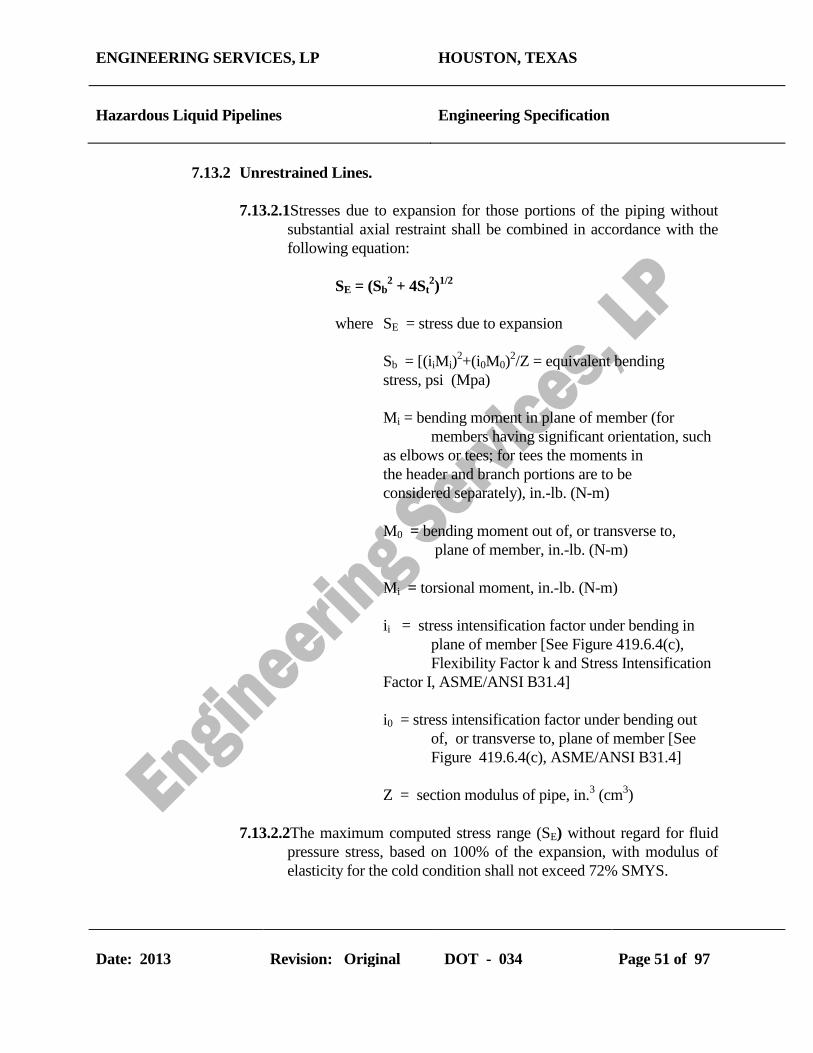
ENGINEERING SERVICES, LP HOUSTON, TEXAS
Hazardous Liquid Pipelines Engineering Specification
Date: 2013 Revision: Original DOT - 034 Page 51 of 97
7.13.2 Unrestrained Lines.
7.13.2.1Stresses due to expansion for those portions of the piping without
substantial axial restraint shall be combined in accordance with the
following equation:
SE = (Sb2 + 4St
2)1/2
where SE = stress due to expansion
Sb = [(iiMi)2+(i0M0)
2/Z = equivalent bending
stress, psi (Mpa)
Mi = bending moment in plane of member (for
members having significant orientation, such
as elbows or tees; for tees the moments in
the header and branch portions are to be
considered separately), in.-lb. (N-m)
M0 = bending moment out of, or transverse to,
plane of member, in.-lb. (N-m)
Mi = torsional moment, in.-lb. (N-m)
ii = stress intensification factor under bending in
plane of member [See Figure 419.6.4(c),
Flexibility Factor k and Stress Intensification
Factor I, ASME/ANSI B31.4]
i0 = stress intensification factor under bending out
of, or transverse to, plane of member [See
Figure 419.6.4(c), ASME/ANSI B31.4]
Z = section modulus of pipe, in.3 (cm
3)
7.13.2.2The maximum computed stress range (SE) without regard for fluid
pressure stress, based on 100% of the expansion, with modulus of
elasticity for the cold condition shall not exceed 72% SMYS.

ENGINEERING SERVICES, LP HOUSTON, TEXAS
Hazardous Liquid Pipelines Engineering Specification
Date: 2013 Revision: Original DOT - 034 Page 52 of 97
7.13.2.3The sum of longitudinal stresses due to pressure, weight, and other
sustained external loadings shall not exceed 54% SMYS (75% x
0.72).
7.13.2.4The sum of longitudinal stresses produced by pressure, live and dead
loads, such as wind or earthquake, shall not exceed 80% SMYS. It
is not necessary to consider wind and earthquake to occur at the
same time.
7.13.3 Analysis - Basic Assumptions and Requirements
7.13.3.1The effects of restraints, such as support friction, branch
connections, lateral interference, etc. shall be considered in the stress
calculations.
7.13.3.2Calculations shall consider stress intensification factors found to
exist in components other than plain straight pipe. Credit may be
taken for extra flexibility of such components. In the absence of
more directly applicable data, the flexibility factors and stress
intensification factors shown in ASME/ANSI B31.4 Figure 419.6.4
(c) may be used.
7.13.3.3Nominal dimensions of pipe and fittings shall be used in flexibility
calculations.
7.13.3.4Calculations of pipe stresses in loops, bends, and offsets shall be
based on the total range from minimum to maximum temperatures.
The linear and angular movements of the equipment which are
connected to the piping system shall be evaluated.
7.13.3.5Calculations of thermal forces and moments on anchors and
equipment such as pumps, meters, and heat exchangers shall be
based on the difference between installation temperature and
maximum operating temperature.
8 CONSTRUCTION, ASSEMBLY, AND FABRICATION
8.1 CONSTRUCTION

ENGINEERING SERVICES, LP HOUSTON, TEXAS
Hazardous Liquid Pipelines Engineering Specification
Date: 2013 Revision: Original DOT - 034 Page 53 of 97
8.1.1 General
New construction, replacement, and maintenance repair of existing systems
shall be in accordance with the requirements of this Plant Engineering
specification and Chapter V, ASME/ANSI B31.4.
8.1.2 Construction Specifications
All work completed in accordance with this specification will require
complete construction specifications which includes this specification,
ASME/ANSI B31.4, and 49CFR195. The construction specifications shall
cover all phases of the work and shall be in sufficient detail to cover the
requirements in the above codes. Construction specifications shall include,
but are not limited to, specific details on handling of pipe, equipment,
materials, welding, and all construction factors which contribute to safety
and sound engineering practice.
8.1.3 Inspection Provisions
8.1.3.1 Company will provide complete inspection coverage for all pipeline
construction and maintenance projects. Inspectors will be qualified
by both experience and training, Minimum qualifications for
inspectors shall be the same qualifications as API 570, “ Inspection,
Repair, Alteration, and Rerating of In-Service Systems”. These
requirements include:
8.1.3.1.1A degree in engineering plus one year of experience in the
design, construction, repair, operation, or inspection of
piping systems.
8.1.3.1.2A 2-year certificate in engineering or technology from a
technical college plus 2 years of experience in the design,
construction, repair, operation, or inspection of piping
systems.
8.1.3.1.3The equivalent of a high school education plus 3 years of
experience in the design, construction, repair, operation, or
inspection of piping systems.
8.1.3.1.4Five years of experience inspecting in-service piping
systems.

ENGINEERING SERVICES, LP HOUSTON, TEXAS
Hazardous Liquid Pipelines Engineering Specification
Date: 2013 Revision: Original DOT - 034 Page 54 of 97
8.1.3.2 Piping inspection for Company construction projects shall insure
quality workmanship with frequent on-site visits. Major
responsibilities include:
8.1.3.2.1Inspect surface of pipe for serious surface defects prior to
coating operation.
8.1.3.2.2Inspect surface of pipe coating prior to lowering-in.
8.1.3.2.3Inspect fitup of joints prior to welding.
8.1.3.2.4Inspect root bead prior to first hot pass.
8.1.3.2.5Inspect completed welds prior to coating.
8.1.3.2.6Inspect condition of ditch bottom prior to lowering in.
8.1.3.2.7Inspect fit of pipe in ditch before backfilling.
8.1.3.2.8Inspect all repairs, replacements, or changes prior to
backfilling.
8.1.3.2.9Supervise and approve nondestructive testing of welds and
electrical testing of coating.
8.1.3.2.10Inspect backfill material prior to use and observe backfill
procedure to assure no damage to the coating during
backfilling.
8.1.4 Right of Way
Right-of-way objectives include:
8.1.4.1 Minimize the possibility of hazard from future industrial or urban
development or encroachment of the right of way.
8.1.4.2 Combine right of way considerations with route selection to
minimize present environmental and physical concerns.

ENGINEERING SERVICES, LP HOUSTON, TEXAS
Hazardous Liquid Pipelines Engineering Specification
Date: 2013 Revision: Original DOT - 034 Page 55 of 97
8.1.4.3 Obtain right of way and associated permits.
8.1.4.4 Survey and stake right of way with marking maintained during
construction.
8.1.4.5 Clear right of way and remove rocks, vegetation, etc. with minimum
damage to the land, prevention of abnormal drainage and soil
erosion.
8.1.4.6 Grade right of way immediately after clearing operations.
8.1.4.7 Construct roadway capable of supporting all vehicles and wide
enough to allow space for the largest sideboom tractor.
8.1.4.8 Maintain signs, lights, guard rails, etc. in the interest of public safety
in constructing pipeline crossings of railroads, highways, streams,
lakes, and rivers.
8.1.4.9 Return right of way to “cleared” condition after construction.
8.1.5 Handling, Hauling, Stringing, and Storing
Care shall be exercised in the handling or storing of pipe, casing, coating
materials, valves, fittings, and other materials to prevent damage. Adequate
precautions shall be taken to damage to yard or mill coatings when hauling,
lifting, and placing on the right of way. Pipe shall not be allowed to drop
and strike objects which will distort, dent, flatten, gouge, or notch the pipe or
damage the coating. Suitable and safe equipment shall be used to lift or
lower the coated pipe.
8.1.6 Damage to Fabricated Items and Pipe
8.1.6.1 Fabricated items such as scraper traps, manifolds, pressure vessels,
etc. shall be inspected before assembly into the mainline or
manifold. Defects shall be repaired in accordance with provisions of
the standard or specification applicable to manufacture.
8.1.6.2 Pipe shall be inspected before coating and before assembly into the
mainline or manifold. Distortion, buckling, denting, flattening,

ENGINEERING SERVICES, LP HOUSTON, TEXAS
Hazardous Liquid Pipelines Engineering Specification
Date: 2013 Revision: Original DOT - 034 Page 56 of 97
gouging, grooves, notches, and other defects shall be repaired as
follows:
8.1.6.2.1Injurious gouges, grooves, or notches shall be removed.
These defects may be repaired by the use of weld procedures
in API 5L. The defects may be removed by grinding
provided the wall thickness is not less than permitted by the
governing pipe material specification.
8.1.6.2.2The damage shall be removed as a cylinder if the conditions
in the above paragraph cannot be met. Insert patching is
prohibited. Weld-on patching, except full encirclement, is
not permitted in pipelines intended to operate at a hoop stress
of more than 20% SMYS of the pipe.
8.1.6.2.3Notches or laminations on pipe ends shall not be repaired.
The damaged end shall be removed as a cylinder and the pipe
end properly rebeveled.
8.1.6.2.4Distorted or flattened lengths shall be discarded.
8.1.6.2.5A dent (as opposed to a scratch, gouge, or groove) may be
defined as a gross disturbance in the curvature of the pipe
wall. A dent containing a stress concentrator, such as a
scratch, gouge, groove, or arc burn, shall be removed by
cutting out the damaged portion of the pipe as a cylinder.
8.1.6.2.6All dents which affect the curvature of the pipe at a seam or
at any girth weld shall be removed as in 8.1.6.2.5 above. All
dents which exceed a maximum depth of 1/4 in. (6 mm) in
pipe NPS 4 and smaller, or 6% of the nominal pipe diameter
in sizes greater than NPS 4, shall not be permitted in
pipelines intended to operate at a hoop stress of more than
20% SMYS. Insert patching, weld overlay, or pounding out
dents shall not be permitted in pipelines intended to operate
at a hoop stress more than 20% SMYS.
8.1.6.2.7Buckled pipe shall be replaced as a cylinder.
ENGINEERING SERVICES, LP HOUSTON, TEXAS
Hazardous Liquid Pipelines Engineering Specification
Date: 2013 Revision: Original DOT - 034 Page 57 of 97
8.1.7 Ditching
8.1.7.1 Depth of ditch shall be appropriate for the route location, surface use
of the land, terrain features, and loads imposed by roadways and
railroads. All buried pipelines shall be installed below the normal
level of cultivation and with a minimum cover not less than the
following table:
Location Normal Excavation
Industrial, commercial, and residential areas 36 in. (0.9m)
River and stream crossings 48 in. (1.2m)
Drainage ditches at roadways and railroads 36 in. (0.9m)
All other areas 30 in. (0.75m)
***If the cover requirements in the above table cannot be met, pipe
may be installed with less cover if additional protection is provided
to withstand anticipated external loads and to minimize damage to
the pipe by external forces.
8.1.7.2 Width and grade of ditch shall provide clearance for lowering of the
pipe into the ditch to minimize damage to the coating and to
facilitate fitting the pipe to the ditch.
8.1.7.3 Location of underground structures intersecting the ditch route shall
be determined prior to construction activities to prevent or minimize
damage to foreign structures. A minimum clearance of 12 in. (0.3m)
shall be maintained between the outside of any buried pipe or
component and the extremity of any other underground structures.
8.1.7.4 Ditching operations shall follow good pipeline practice and
consideration of public safety. API RP 1102 will provide additional
guidance.
8.1.8 Bends, Elbows, and Miters in Steel Pipelines
8.1.8.1 Changes in direction and elevation may be made by the use of bends
and elbows. Design requirements for bends and elbows are provided
in Section 7, Design, in this specification.

ENGINEERING SERVICES, LP HOUSTON, TEXAS
Hazardous Liquid Pipelines Engineering Specification
Date: 2013 Revision: Original DOT - 034 Page 58 of 97
8.1.8.2 Wrinkle and miter bends are not allowed on Company pipelines.
8.1.8.3 The maximum degree of field cold bends in pipe sizes NPS 12 and
larger may be determined by the table in paragraph 404.2.1,
ASME/ANSI B31.4. Field cold bends may be made with a shorter
radius provided all other requirements of the section are met. Wall
thickness after bending shall meet minimum requirements of the
specification. Circumferential welds in the bend section shall be
radiographed.
8.1.9 Welding
All welding requirements are summarized in Section 6, Welding, of this
specification and paragraph 434.8, Welding, ASME/ANSI B31.4.
8.1.10 Tie In
Gaps left in the continuous line construction at river, canal, highway, or
railroad crossings require special consideration for alignment and welding.
Sufficient equipment shall be available and care exercised not to force or
strain the pipe to proper alignment.
8.1.11 Installation of Pipe in Ditch
8.1.11.1 Lowering of the pipe into the ditch shall be permitted only when a
Company Pipeline Inspector is on location. Special emphasis will be
placed on pipe condition before and after lowering, and the overall
condition of the ditch.
8.1.11.2Stresses induced into the pipe during construction must be
minimized. Pipe shall lay in the ditch with minimum application of
outside forces.
8.1.12 Backfilling
8.1.12.1Backfilling shall be performed to provide firm, continuous support
under the pipe.
8.1.12.2 When backfilling with material containing rocks, no rocks shall be
closer to the pipe than 12 inches. A “rock-free” cylinder of sand or
dirt shall be placed around the pipe maintaining the required 12
ENGINEERING SERVICES, LP HOUSTON, TEXAS
Hazardous Liquid Pipelines Engineering Specification
Date: 2013 Revision: Original DOT - 034 Page 59 of 97
inches of small-particle backfill material. In addition, rock shield are
required when the backfill material contains rocks over 4 inches in
diameter.
8.1.13 Hot Taps
All hot taps shall be installed by trained and experienced crews in
accordance with Company Safety and Health Standards and written
engineering specifications and procedures which are unique for each job.
8.1.14 Restoration of Right of Way and Cleanup
These operations shall follow good construction practices and considerations
of private and public safety. Cleanup includes removal and disposition of
refuse and surplus materials from the right-of-way. Also included in
cleanup is leveling the right of way by filling deep ruts and removing or
leveling mounds of earth.
8.1.15 Special Crossings
8.1.15.1Protection of Pipelines From Hazards
Pipelines which must be installed in locations where high loading
may occur due to natural hazards shall be constructed with increased
wall thickness, moving soil containment, erosion prevention, and
weight/ anchor installation.
8.1.15.2Water Crossings
Water crossings including underwater construction are covered in
paragraph 434.13.1, ASME/ANSI B31.4.
8.1.15.3Overhead Structures
Overhead structures used to suspend pipelines shall be designed and
constructed with good engineering practices and within the
restrictions and/or regulations of the governing body with
jurisdiction for the pipeline. Detailed plans and specifications shall
be prepared. Adequate inspection shall be provided to assure
complete adherence to the construction specifications.
8.1.15.4Bridge Attachments
The use of higher strength light-weight pipe, proper design and
installation of hangers, and special protection to prevent damage by

ENGINEERING SERVICES, LP HOUSTON, TEXAS
Hazardous Liquid Pipelines Engineering Specification
Date: 2013 Revision: Original DOT - 034 Page 60 of 97
the elements or bridge and approach traffic shall be considered. Any
agreed upon restrictions or precautions shall be contained in the
detailed job specifications. Inspectors shall assure the Company that
these requirements are met.
8.1.15.5Railroad and Highway Crossings
8.1.15.5.1Safety of the general public and the prevention of damage
to the pipeline by reason of its location are primary
considerations. Construction specifications shall cover the
procedure for these crossings based upon the requirements of
the specific location.
8.1.15.5.2Installation of uncased carrier pipe is preferred.
Installation of carrier pipe, or casing if used, shall be in
accordance with API RP 1102. If casing is used, coated
carrier pipe shall be independently supported outside each
end of the casing and insulated from the casing throughout
the cased section. Casing ends shall be sealed using a
durable, electrically nonconductive material in the annular
space between the casing and pipe.
8.1.15.5.3The sum of the circumferential stresses due to internal
design pressure and external load for pipe installed under
railroads and highways without use of casing shall not
exceed the allowable circumferential stresses summarized in
paragraph 402.3.2, ASME/ANSI B31.4.
8.1.16 Block and Isolating Valves
8.1.16.1 General
8.1.16.1.1Block and isolating valves shall be installed for limiting
hazard and damage from accidental discharge and for
facilitating maintenance of the piping systems.
8.1.16.1.2Valves shall be located at accessible points on the pipeline,
protected from damage or tampering, and suitably supported
to prevent differential settlement or movement of the

ENGINEERING SERVICES, LP HOUSTON, TEXAS
Hazardous Liquid Pipelines Engineering Specification
Date: 2013 Revision: Original DOT - 034 Page 61 of 97
attached piping. An operating device to open or close the
block valve shall be protected and accessible only to
authorized persons.
8.1.16.2 Mainline Valves
8.1.16.2.1Mainline block valves shall be installed on the upstream of
major river crossings and public water supply reservoirs.
Either a block or check valve shall be installed on the
downstream side of major river crossings and public water
supply reservoirs.
8.1.16.2.2A mainline block valve shall be installed at mainline pump
stations. A block or check valve shall be installed at other
locations appropriate for the terrain features. In industrial,
commercial, and residential areas where construction
activities pose a particular risk of external damage to the
pipeline, provisions shall be made for the appropriate spacing
and location of mainline valves consistent with the type of
liquids being transported.
8.1.16.2.3A remotely operated mainline block valve shall be
provided at remotely controlled pipeline facilities to isolate
segments of the pipeline.
8.1.16.3 Pump Station, Tank Farm, and Terminal Valves
8.1.16.3.1Valves shall be installed on the suction and discharge of
pump stations to assure the pipeline can be isolated from the
pump station.
8.1.16.3.2Valves shall be installed on lines entering or leaving tank
farms or terminals at convenient locations. The tank farm or
terminal may then be isolated from other facilities such as the
pipeline, manifolds, or pump stations.
8.1.17 Connections to Main Lines
Where connections to the main line such as branch lines, jump-overs, relief
valves, air vents, etc. are made to the main pipeline, these components shall
ENGINEERING SERVICES, LP HOUSTON, TEXAS
Hazardous Liquid Pipelines Engineering Specification
Date: 2013 Revision: Original DOT - 034 Page 62 of 97
be installed in accordance with paragraph 404.3.1, ANSI B31.4 and Branch
Connection paragraph in Section 7 of this Plant Engineering Specification.
All damaged coating shall be removed and new coating shall be applied on
the attachments as well as the pipeline coating that was removed for repair.
8.1.18 Scraper Traps
8.1.18.1Scraper traps (pig receivers and launchers) shall be installed as
required by Company Specifications, Plant Engineering
Specifications and DOT Regulation 49CFR195. All pipe, valves,
fittings, closures, and appurtenances shall comply with this Plant
Engineering Specification, ASME/ANSI B31.4, and 49CFR195.
8.1.18.2Scraper traps on pipelines shall be designed with sufficient length to
run an instrument pig.
8.1.18.3Receiver traps on mainlines which are connected to piping or
manifolding shall be anchored below ground with adequate concrete
anchors when required and suitably supported aboveground to
prevent transmission of line stresses due to expansion and
contraction to connecting facilities.
8.1.18.4Scraper trap and components shall be assembled in accordance with
paragraph 435, Assembly of Piping Components, ASME/ANSI
B31.4.
8.1.19 Line Markers
Adequate pipeline location markers indicating caution for the protection of
the pipeline, the public, and persons performing work in the area shall be
installed over each pipeline during all construction activities. These location
markers shall be installed on each side of roads, highways, railroads, and
stream crossings. Markers with requirements of regulatory agencies shall be
installed on each side of navigable stream crossings. API RP 1109 shall be
used for guidance.
8.1.20 Corrosion Control
External and internal corrosion control shall be completed as required in
Chapter VIII, Corrosion Control, ASME/ANSI B31.4, Company
Specifications, Plant Engineering Specifications, and DOT 49CFR195.

ENGINEERING SERVICES, LP HOUSTON, TEXAS
Hazardous Liquid Pipelines Engineering Specification
Date: 2013 Revision: Original DOT - 034 Page 63 of 97
8.1.21 Pump Station, Tank Farm, and Terminal Construction
8.1.21.1General
All construction work performed on DOT regulated piping systems
associated with pump stations, tank farms, terminals and equipment
installations shall be done under construction specifications.
Specifications shall cover all phases of the contract work and shall
be in sufficient detail to insure that the requirements of this Plant
Engineering Specification, ASME/ANSI B31.4, and 49CFR195
shall be met. Construction specifications shall include specific
details on soil conditions, foundations and concrete work, steel
fabrication and building erection, piping, welding, equipment and
materials, and all construction factors contributing to safety and
sound engineering practice.
8.1.21.2Location
Company pump stations, tank farms, or terminals shall be located
when possible with safe distances from adjacent properties not under
control of the Company to minimize the communication of fire from
structures on adjacent properties. Similar consideration shall be
given to its relative location from the station manifolds, tankage,
maintenance facilities, personnel housing, etc. Sufficient open space
shall be left around the building and manifolds to provide access for
maintenance equipment and fire fighting equipment. Station, tank
farm, and terminal shall be fenced to minimize trespass. Roadways
and gates should be located to provide ready access to or egress from
the facilities.
8.1.21.3Building Installation
Buildings shall be located and constructed to comply with detailed
plans and specifications. Excavation for and installation of
foundations and erection of the building shall be done by craftsmen
familiar with the respective phase of the work. All work shall be
done in a safe and workmanlike manner. Inspection shall be
provided to assure that the requirements of the plans and
specifications are met.
8.1.21.4Pumping Equipment and Prime Movers

ENGINEERING SERVICES, LP HOUSTON, TEXAS
Hazardous Liquid Pipelines Engineering Specification
Date: 2013 Revision: Original DOT - 034 Page 64 of 97
Installation of pumping equipment and prime movers shall be
covered by detailed plans and specifications which have taken into
account the variables inherent in local soil conditions, utilization,
and arrangement of the equipment to provide the optimum in
operating ease and maintenance access. Machinery shall be handled
and mounted in accordance with recognized millwright practice and
shall be provided with protective covers to prevent damage during
construction. Manufacturer’s recommendations concerning
installation details for auxiliary piping, setting, and aligning shall be
considered as minimum requirements.
8.1.21.5Pump Station, Tank Farm, and Terminal Piping
All piping including, but not limited to, main unit interconnections,
manifolds, scraper traps, etc. which can be subjected to mainline
pressure shall be constructed in accordance with Plant Engineering
Specifications (Section 6, Welding), corrosion control requirements
in Company specifications, and ASME/ANSI B31.4.
8.1.21.6Controls and Protective Equipment
Pressure controls and protective equipment, including pressure
limiting devices, regulators, controllers, relief valves, and other
safety devices as shown on the drawings or required by the
specifications shall be installed by competent and skilled workmen.
Installation shall be completed with careful handling and minimum
exposure of instruments and devices to inclement weather
conditions, dust, or dirt to prevent damage. Piping, conduits, or
mounting brackets shall not cause the instruments or devices to be
distorted or in any significant strain. Instruments and devices shall
be installed to enable checks to be done without undue interruptions
in operations. After installation, controls and protective equipment
shall be tested under conditions approximating actual operations to
assure proper installation and function.
8.1.22 Storage and Working Tankage
8.1.22.1General
All construction work performed on storage and working tankage
and allied equipment, piping, and facilities shall be done under
construction specifications. These specifications shall cover all

ENGINEERING SERVICES, LP HOUSTON, TEXAS
Hazardous Liquid Pipelines Engineering Specification
Date: 2013 Revision: Original DOT - 034 Page 65 of 97
phases of the work under contract and shall be in sufficient detail to
insure that all requirements are met. Specifications shall include
specific details on soil conditions, foundations and concrete work,
tank fabrication and erection, piping, welding, equipment and
materials, dikes, and all construction factors contributing to safety
and sound engineering practices.
8.1.22.2Location
8.1.22.2.1Location requirements and considerations are identical to
paragraph 8.1.21.2 above.
8.1.22.2.2Spacing of tankage shall be governed by the requirements
of ANSI/NFPA 30.
8.1.22.3 Tanks and Pipe-Type Storage
8.1.22.3.1Tanks for storage or handling crude oil and liquid
petroleum products and liquid alcohols having vapor
pressures approximating atmospheric shall be constructed in
accordance with ANSI/API 650, API 12B, API 12D, API
12F, or designed and constructed in accordance with
accepted good engineering practices.
8.1.22.3.2Tanks for storage or handling petroleum products and
liquid alcohols having vapor gage pressures of 0.5 psi (0.035
bar) but not exceeding 15 psi (1 bar) shall be constructed in
accordance with ANSI/API 620.
8.1.22.3.3Tanks used for storage and handling liquids having vapor
gage pressures greater than 15 psi (1 bar) shall be designed
and constructed in accordance with design of accredited tank
builders and the ASME Boiler and Pressure Vessel Code,
Section VIII, Division 1 or 2.
8.1.22.4Foundations
Tank foundations shall be constructed in accordance with plans and
specifications which shall take into account local soil conditions,
type of tank, usage, and general location.

ENGINEERING SERVICES, LP HOUSTON, TEXAS
Hazardous Liquid Pipelines Engineering Specification
Date: 2013 Revision: Original DOT - 034 Page 66 of 97
8.1.22.5Dikes or Firewalls
Dikes and firewalls may be required for protection of the pipeline’s
station, tank farm, terminal or other facilities from damage by fire
from adjacent facilities. Tank dikes and firewalls shall be
constructed to meet the capacity requirements in ANSI/NFPA 30.
8.1.23 Electrical Installations
8.1.23.1General
Electrical installations for lighting, power, and control shall be
covered by detailed plans and specifications. Installations shall be in
accordance with codes applicable to the specific type of circuitry and
classification of areas for electrical installation. Inspection shall be
provided and all circuitry shall be tested before operation to assure
that the installation was made in workmanlike manner to provide for
the continuing safety of personnel and equipment. Installations shall
be made in accordance with ANSI/NFPA 70 and API RP 500C.
8.1.23.2Care and Handling of Materials
All electrical equipment and instruments shall be carefully handled
and properly stored or enclosed to prevent damage, deterioration, or
contamination during construction. Packaged components are not to
be exposed during construction. Equipment susceptible to damage
or deterioration by exposure to humidity shall be adequately
protected by using appropriate means such as plastic film enclosures,
desiccants, or electrical heating.
8.1.23.3Installation
Installation of electrical materials shall be made by qualified
personnel familiar with details of electrical aspects and code
requirements for such installation. Care shall be exercised to prevent
damage to the insulation of cable and wiring. Partially-complete
installations shall be protected from damage during construction.
Installation design and specifications shall give consideration to the
need for dust and/or moisture-proof enclosures for special gear as
relays, small switches, and electronic components. The frames of
electric motors or other grounded electrical equipment shall not be
used as the ground connection for electrical welding.

ENGINEERING SERVICES, LP HOUSTON, TEXAS
Hazardous Liquid Pipelines Engineering Specification
Date: 2013 Revision: Original DOT - 034 Page 67 of 97
8.1.24 Liquid Metering
8.1.24.1Positive displacement meters, turbine meters, or equivalent liquid
measuring devices and their proving facilities shall be designed and
installed in accordance with the API Manual of Petroleum
Measurement Standards.
8.1.24.2Provisions shall be made to permit access to these facilities by
authorized personnel only.
8.1.24.3Assembly of the metering facility components shall be in
accordance with paragraph 435, Assembly of Piping Components,
ASME/ANSI B31.4.
8.1.25 Liquid Strainers and Filters
8.1.25.1Strainers and filters shall be designed to the same pressure
limitations and subjected to the same test pressures as the piping
system in which the equipment is installed. Assemblies shall be
supported to prevent undue loading on the connected piping system.
8.1.25.2Installation and design shall provide for ease of maintenance and
servicing without interference with the station operation.
8.1.25.3The filtering medium should be of such retention size and capacity
to fully protect the facilities against intrusion of harmful foreign
substances.
8.1.25.4Assembly of strainers or filters and their components shall be in
accordance with paragraph 435, Assembly of Piping Components,
ASME/ANSI B31.4
8.2 ASSEMBLY OF PIPING COMPONENTS
8.2.1 General
Mechanically-complete piping construction shall conform to the
requirements of this Plant Engineering Specification and ASME/ANSI
B31.4.

ENGINEERING SERVICES, LP HOUSTON, TEXAS
Hazardous Liquid Pipelines Engineering Specification
Date: 2013 Revision: Original DOT - 034 Page 68 of 97
8.2.2 Bolting Procedure
8.2.2.1 All flanged joints shall be fitted up to assure gasket contact faces
bear uniformly on the gasket. Bolts shall be made-up with uniform
stress.
8.2.2.2 In bolting gasket flanged joints, the gasket shall be properly
compressed in accordance with the design principles for the type of
gasket used.
8.2.2.3 All bolts or studs shall extend completely through their nuts in the
tightened condition.
8.2.3 Pumping Unit Piping
8.2.3.1 Piping to main pumping units shall be designed and supported to
minimize stress or load in any component of the system.
8.2.3.2 Design and assembly shall consider the forces of expansion and
contraction to minimize these effects within the assembly.
8.2.3.3 All valves and fittings on pumping units shall carry the same
pressure ratings as required for pipeline operating pressures.
8.2.3.4 Welding shall be completed in accordance with Section 6 of this
specification and paragraph 434.8, ASME/ANSI B31.4.
8.2.3.5 Bolting shall be completed in accordance with paragraph 8.2.2.
8.2.4 Manifolds
8.2.4.1 All components within a manifold assembly including valves,
flanges, fittings, headers, and special assemblies shall withstand the
operating pressures and specified loadings for the specific service
piping to which it is connected.
8.2.4.2 Meter banks, prover loops, and scraper traps shall be subject to the
same assembly requirements as manifolds.
ENGINEERING SERVICES, LP HOUSTON, TEXAS
Hazardous Liquid Pipelines Engineering Specification
Date: 2013 Revision: Original DOT - 034 Page 69 of 97
8.2.4.3 Manifold headers with multiple outlets shall have outlets designed as
covered in ASME/ANSI B31.4, paragraphs 404.3.1(b) and
404.3.1(e) as illustrated in Figures 404.3.1(b)(3) and
404.3.1(d)(2), respectively. Jigs may be used to assure alignment of
outlets and flanges with other components. The fabricated unit shall
be stress relieved, if required, before removal from the jig.
8.2.4.4 Manifold headers assembled from wrought tees, fittings, and flanges
may be assembled with jigs to assure alignment of components.
Stress relieving should be considered.
8.2.4.5 All welding on manifolds and headers shall conform to paragraph
434.8, ASME/ANSI B31.4.
8.2.5 Final assembly of all components shall minimize locked-in stresses. The
entire assembly shall be adequately supported to provide minimum
unbalance and vibration.
9 INSPECTION AND TESTING
9.1 INSPECTION
9.1.1 General
Construction inspection provisions for pipelines and related facilities shall
be adequate to assure compliance with the material, construction, welding,
assembly, and testing requirements of this plant engineering specification,
ASME/ANSI B31.4, and 49CFR195.
9.1.2 Qualification of Inspectors
9.1.2.1 Inspection personnel shall be qualified by training and experience.
Authorized piping inspectors shall have education and experience
equal to at least one of the following:
9.1.2.1.1A degree in engineering plus one year of experience in the
design, construction, repair, operation, or inspection of
piping systems.

ENGINEERING SERVICES, LP HOUSTON, TEXAS
Hazardous Liquid Pipelines Engineering Specification
Date: 2013 Revision: Original DOT - 034 Page 70 of 97
9.1.2.1.2A 2-year certificate in engineering or technology from a
technical college plus 2 years of experience in the design,
construction, repair, operation, or inspection of piping
systems.
9.1.2.1.3The equivalent of a high school education plus 3 years of
experience in the design, construction, repair, operation, or
inspection of piping systems.
9.1.2.1.4Five (5) years of experience inspecting in-service piping
systems.
9.1.2.2 Company inspection personnel shall be capable of performing the
following inspection services:
9.1.2.2.1Right of way and grading.
9.1.2.2.2Ditching.
9.1.2.2.3Line up and pipe surface inspection.
9.1.2.2.4Welding.
9.1.2.2.5Coating and cathodic protection.
9.1.2.2.6Tie-in and lowering.
9.1.2.2.7Backfilling and clean up.
9.1.2.2.8Pressure testing.
9.1.2.2.9Station construction
.
9.1.2.2.10River crossings.
9.1.2.2.11Electrical installation
.
9.1.2.2.12Corrosion control (external and internal).
9.1.3 Type and Extent of Examination Required

ENGINEERING SERVICES, LP HOUSTON, TEXAS
Hazardous Liquid Pipelines Engineering Specification
Date: 2013 Revision: Original DOT - 034 Page 71 of 97
9.1.3.1 Visual
9.1.3.1.1 Material
9.1.3.1.1.1All piping components shall be visually inspected
to insure that no mechanical damage has occurred
during shipment and handling prior to being
connected into the piping system.
9.1.3.1.1.2All pipe shall be visually inspected to identify
dents, grooves, gouges, notches, buckling, arc strikes,
weld defects, laminations, split ends, and other pipe
defects.
9.1.3.1.1.3On systems where pipe is telescoped by grade,
wall thickness, or both, particular care shall be taken
to insure proper placement of pipe. Permanent
records shall be kept showing the location of each
grade, wall thickness, type, specification, and
manufacturer of the pipe.
9.1.3.1.2 Construction
9.1.3.1.2.1Visual inspection for detection of surface defects
in the pipe shall be provided for each job just ahead
of any coating operation and during the lowering-in
and backfill operation.
9.1.3.1.2.2The pipe swabbing operation shall be inspected
for thoroughness to provide a clean surface.
9.1.3.1.2.3Before welding, the pipe shall be examined for
damage-free bevels and proper alignment of the joint.
9.1.3.1.2.4The stringer bead shall be inspected, particularly
for cracks, before subsequent beads are applied.

ENGINEERING SERVICES, LP HOUSTON, TEXAS
Hazardous Liquid Pipelines Engineering Specification
Date: 2013 Revision: Original DOT - 034 Page 72 of 97
9.1.3.1.2.5The completed weld shall be cleaned and
inspected prior to coating operations. Irregularities
that could protrude through the coating shall be
removed.
9.1.3.1.2.6When the pipe is coated, inspection shall be made
to determine that the coating machine does not cause
harmful gouges or grooves in the pipe surface.
9.1.3.1.2.7Lacerations of the pipe coating shall be inspected
prior to repair of coating to see if the pipe surface has
been damaged. Damaged coating and pipe shall be
repaired before the pipe is lowered in the ditch.
9.1.3.1.2.8All repairs, changes, or replacements shall be
inspected before they are covered up.
9.1.3.1.2.9The condition of the ditch shall be inspected
before the pipe is lowered in to assure proper
protection of pipe and coating. For underwater
crossings, the condition of the ditch and fit of the
pipe to the ditch shall be inspected when feasible.
9.1.3.1.2.10The fit of the pipe to ditch shall be inspected
before the backfilling operations.
9.1.3.1.2.11The backfilling operations shall be inspected for
quality and compaction of backfill, placement of
material for the control of erosion, and possible
damage to the pipe coatings.
9.1.3.1.2.12Cased crossings shall be inspected during
installation to determine that the carrier pipe is
supported, sealed, and insulated from the casing.
9.1.3.1.2.13River crossings shall have thorough inspection
and shall be surveyed and profiled after construction.

ENGINEERING SERVICES, LP HOUSTON, TEXAS
Hazardous Liquid Pipelines Engineering Specification
Date: 2013 Revision: Original DOT - 034 Page 73 of 97
9.1.3.1.2.14All piping components other than pipe shall be
inspected to insure damage-free condition and proper
installation.
9.1.3.2 Supplementary Types of Examination
9.1.3.2.1Testing of field and shop welds shall be made in accordance
with Section 6, Welding, this Plant Engineering Specification
and paragraph 434.8.5, Welding Quality, ASME/ANSI
B31.4.
9.1.3.2.2Welding defects shall be repaired in accordance with
paragraph 434.8.7, Repair and Removal of Weld Defects,
ASME/ANSI B31.4 and Section 6, Welding, of this Plant
Engineering Specification.
9.1.3.2.3Coated pipe shall be inspected in accordance with paragraph
461.1.2, Protective Coating, ASME/ANSI B31.4.
9.1.4 Repair of Defects
9.1.4.1 Defects of fabricated items and in pipe wall shall be repaired or
eliminated in accordance with paragraph 434.5, Damage to
Fabricated Items and Pipe, ASME/ANSI B31.4.
9.1.4.2 Welding defects shall be repaired in accordance with paragraph
434.8.7, Repair or Removal of Defects, ASME/ANSI B31.4 and
Section 6, Welding, of this Plant Engineering Specification.
9.1.4.3 Holidays or other damage to coating shall be repaired in accordance
with paragraph 461.1.2, Protective Coatings, ASME/ANSI B31.4.
9.2 TESTING
9.2.1 General
In order to meet requirements of this Plant Engineering Specification, it is
necessary that tests be made upon the completed system and upon
component parts of the finished system. When reference in this plant
engineering specification is made to tests or portions of tests described in

ENGINEERING SERVICES, LP HOUSTON, TEXAS
Hazardous Liquid Pipelines Engineering Specification
Date: 2013 Revision: Original DOT - 034 Page 74 of 97
other codes and specifications, they shall be considered as a part of this
specification. Should leaks occur on tests, the line section or component
part shall be repaired or replaced and retested in accordance with this Plant
Engineering Specification and ASME/ANSI B31.4.
9.2.1.1 Testing of Fabricated Items
9.2.1.1.1Fabricated items such as scraper traps, manifolds, volume
chambers, etc., shall be hydrostatically tested to limits equal
to or greater than those required of the completed system.
This test may be conducted separately or as a part of the
completed system.
9.2.1.1.2In testing fabricated items before installation, the applicable
paragraphs of specifications listed in Table 423.1, Materials
Standards, ASME/ANSI B31.4 shall apply.
9.2.1.2 Testing After New Construction
9.2.1.2.1Systems or Parts of Systems
9.2.1.2.1.1All liquid transportation piping systems within the
scope of this Plant Engineering Specification,
regardless of stress, shall be tested after construction.
9.2.1.2.1.2Systems to be operated at a hoop stress greater
than 20% SMYS shall be hydrostatically tested to
1.25 times the design pressure. Hydrotest pressure
shall be maintained for four (4) hours. API RP 1110
may be used for guidance in hydrotesting.
9.2.1.2.1.3Leak testing in lieu of hydrotest for pipelines
operating at less than 20% SMYS is not
recommended. This alternative is approved by
paragraph 437.1.3(a)(3), ASME/ANSI B31.4.
9.2.1.2.1.4When testing piping, the test pressure shall not
exceed that stipulated in the standards of materials
specifications (except pipe) incorporated in this
specification by reference and listed in Table 423.1,

ENGINEERING SERVICES, LP HOUSTON, TEXAS
Hazardous Liquid Pipelines Engineering Specification
Date: 2013 Revision: Original DOT - 034 Page 75 of 97
Materials Standards, ASME/ANSI B31.4 for the
weakest element in the system, or portion of system,
being tested.
9.2.1.2.1.5Equipment not to be subjected to test pressure
shall be disconnected from the piping or otherwise
isolated. Valves may be used for isolation if valve
including closing mechanism is suitable for the test
pressure.
9.2.1.2.2Testing Tie-Ins
Radiography or other nondestructive testing methods may be
used in lieu of hydrotesting to test tie-in welds.
9.2.1.2.3Testing Controls and Protective Equipment
All controls and protective equipment, including pressure
limiting devices, regulators, controllers, relief valves, and
other safety devices, shall be tested to determine that they
are:
(a) In good mechanical condition.
(b) Of adequate capacity, effectiveness,
and reliability of operation for the service in
which they are used.
(c) Functioning at the correct pressure.
(d) And properly installed and protected
from foreign materials or other conditions
that might prevent proper operation.
9.2.2 Test Pressure
9.2.2.1 Hydrostatic Testing of Internal Pressure Piping
9.2.2.1.1Portions of piping systems to be operated at a hoop stress
greater than 20% SMYS shall be hydrotested to a proof test
equivalent at least 1.25 times the internal design pressure.
Test pressure shall be maintained for at least four (4) hours.
ENGINEERING SERVICES, LP HOUSTON, TEXAS
Hazardous Liquid Pipelines Engineering Specification
Date: 2013 Revision: Original DOT - 034 Page 76 of 97
9.2.2.1.1.1If visual inspection is possible for all pressurized
piping component during the four hour test and there
is no leakage, these piping components require no
further testing.
9.2.2.1.1.2On those portions of piping systems where visual
inspection is not possible during hydrotest, the proof
test shall be followed by a reduced leak test
equivalent to 1.1 times the internal design pressure
for at least four hours.
9.2.2.1.2API RP 1110 may be used for guidance for the hydrostatic
test.
9.2.2.1.3Hydrostatic tests should be conducted with water which has
been treated for bacteria and corrosion control. Liquid
petroleum that does not vaporize may be used if the
following conditions are met.
9.2.2.1.3.1The pipeline section under test is outside
populated areas.
9.2.2.1.3.2Each building within 300 ft (90 m) of the test
section is unoccupied while the test pressure is equal
to or greater than a pressure which produces a hoop
stress of 50% SMYS.
9.2.2.1.3.3The test section is kept under surveillance by
regular patrols during test.
9.2.2.1.3.4Communication is maintained along the test
section.
9.2.2.1.4Provisions shall be made for relief of excess pressure, if the
testing medium will be subject to thermal expansion during
the test. Effects of temperature changes shall be taken into
account when interpretations are made of the recorded test
pressure.

ENGINEERING SERVICES, LP HOUSTON, TEXAS
Hazardous Liquid Pipelines Engineering Specification
Date: 2013 Revision: Original DOT - 034 Page 77 of 97
9.2.2.2 Leak Testing
A one (1) hour hydrostatic or pneumatic leak test may be used for
piping systems to be operated at a hoop stress of 20% or less of the
SMYS of the pipe. The hydrostatic test pressure shall be not less
than 1.25 times the internal design pressure. The pneumatic-test
gage-pressure shall be 100 psi (7 bar) or that pressure which would
produce a hoop stress of 25% SMYS of the pipe, whichever pressure
is least.
9.2.3 Qualification Tests
The following procedures shall be followed without exception if
qualification tests are required in other sections of this Plant Engineering
Specification and ASME/ANSI B31.4.
9.2.3.1 Visual Examination
Used or new pipe to be laid on Company pipeline projects shall be
visually inspected in accordance with paragraph 9.1.3.1.1 of this
section and paragraph 436.5.1, ASME/ANSI B31.4.
9.2.3.2 Bending Properties
9.2.3.2.1For pipe of unknown specification or ASTM A120, bending
properties are required if minimum yield strength used for
design is above 24,000 psi (165 MPa) and after type of joint
has been identified in accordance with paragraph 9.2.3.4
below.
9.2.3.2.2For pipe NPS 2 and smaller, bending test shall meet the
requirements of ASTM A53 or API 5L.
9.2.3.2.3For pipe larger than NPS 2, flattening tests shall meet the
requirements in ASTM A53, API 5L, or API 5 LU.
9.2.3.2.4The number of tests required to determine bending
properties shall be the same as required in paragraph 9.2.3.6
to determine yield strength.

ENGINEERING SERVICES, LP HOUSTON, TEXAS
Hazardous Liquid Pipelines Engineering Specification
Date: 2013 Revision: Original DOT - 034 Page 78 of 97
9.2.3.3 Determination of Wall Thickness
9.2.3.3.1Wall thickness shall be determined by measuring the
thickness at quarter points (3, 6, 9, 12 clock positions) on one
end of each piece of pipe. Measurement shall be made on
not less than 5% of the individual lengths, but not less than
10 lengths, if the lot of pipe is known to be of uniform grade,
size, and nominal thickness. Thickness measurement of the
other lengths may be verified by applying a gage set to the
minimum thickness.
9.2.3.3.2The nominal wall thickness shall be taken as the next
nominal wall thickness below the average of all
measurements taken. Thickness limitations are:
9.2.3.3.2.1Pipe under NPS 20: wall thickness selected must
be equal to or less than 1.14 times the least measured
thickness.
9.2.3.3.2.2Pipe NPS 20 and larger: wall thickness selected
must be equal to or less than 1.11 times the least
measured thickness.
9.2.3.4 Determination of Weld Joint Factor
The weld joint factor E (Table 402.4.3, ASME/ANSI B31.4) may be
used if the type of longitudinal or spiral weld joint is known. E shall
not exceed 0.60 for pipe NPS 4 and smaller, or 0.80 for pipe over
NPS 4.
9.2.3.5 Weldability
9.2.3.5.1Weldability shall be determined for steel pipe of unknown
specifications. A qualified pipe welder shall make a girth
weld to join two joints of pipe. Visual and radiographic
examinations shall be completed on the weld in accordance
with API 1104. Standards of Acceptability-Nondestructive
Testing, API 1104 shall be used to determine the weld
quality.
ENGINEERING SERVICES, LP HOUSTON, TEXAS
Hazardous Liquid Pipelines Engineering Specification
Date: 2013 Revision: Original DOT - 034 Page 79 of 97
9.2.3.5.2At least one test weld shall be made and tested for each
number of lengths to be used in the Company project as
listed below. All test specimens shall be selected at random.
Minimum Number of Test Weld
Nominal Pipe Size Number of Lengths per Test
Less than 6 400
6 through 12 100
Larger than 12 50
9.2.3.6 Determination of Yield Strength
9.2.3.6.1Tensile properties (specified minimum yield strength,
minimum tensile strength, and minimum percent elongation)
may be established by performing all tensile tests required by
API 5L or API 5 LU. All test specimens shall be selected at
random. Minimum number of tests per joints of pipe are as
follows:
Minimum Number of Test Welds
Nominal Pipe Size Number of Lengths per Test
Less than 6 200
6 through 12 100
Larger than 12 50
9.2.3.7 Minimum Yield Strength Value
For pipe of unknown specifications, the minimum yield strength may
be determined by averaging the value of all yield strength tests for a
test lot. The minimum yield strength shall be taken as the lesser of
the following:
9.2.3.7.180% of the average value of the yield strength tests.
9.2.3.7.2The minimum value of any yield strength test, except that
no value may exceed 52,000 psi (358 Mpa).
9.2.3.7.324,000 psi (165 Mpa) if the average yield-tensile ratio
exceeds 0.85.
9.2.4 Records

ENGINEERING SERVICES, LP HOUSTON, TEXAS
Hazardous Liquid Pipelines Engineering Specification
Date: 2013 Revision: Original DOT - 034 Page 80 of 97
Company shall maintain a record relative to design, construction, and testing
of each pipeline within the scope of this specification. These records shall
include:
9.2.4.1 Materials specifications.
9.2.4.2 Route maps and alignment sheets for “as-built” condition.
9.2.4.3 Location of each pipe size, grade, wall thickness, type of seam (if
any, and manufacturer.
9.2.4.4 Coatings and cathodic protection.
These records shall be maintained for the life of the facility.
10 OPERATION AND MAINTENANCE PROCEDURES
10.1 OPERATION AND MAINTENANCE PROCEDURES AFFECTING THE
SAFETY OF LIQUID TRANSPORTATION PIPING SYSTEMS
10.1.1 General
10.1.2 Operations and Maintenance Plans and Procedures
The following operation and maintenance plans and procedures are
documented in Company Specifications and Procedures and comply with the
requirements in this specification, ASME/ANSI B31.4, and DOT
49CFR195.
10.1.2.1Written detailed plans and training programs for employees
covering operating and maintenance procedures for hazardous liquid
pipeline systems during normal operation in accordance with the
requirements in this specification. Essential features in the plans for
specific portions of the system are outlined in paragraphs 10.2 and
10.3 below.
10.1.2.2Plan for external and internal corrosion control of new and existing
piping systems, including requirements in this specification and
other Company specification concerning corrosion control.

ENGINEERING SERVICES, LP HOUSTON, TEXAS
Hazardous Liquid Pipelines Engineering Specification
Date: 2013 Revision: Original DOT - 034 Page 81 of 97
10.1.2.3Written emergency plan for implementation in the event of system
failures, accidents, or other emergencies; training programs for
operation and maintenance employees with regard to applicable
portions of the plan; establish liaison with appropriate public
officials with respect to the plan.
10.1.2.4Plan for reviewing changes in conditions affecting the integrity and
safety of the piping system.
10.1.2.5Liaison with local authorities and other pipeline operators who issue
construction permits to prevent accidents caused by excavators.
10.1.2.6Procedures to analyze all failures and accidents to determine the
cause and to minimize the possibility of recurrence.
10.1.2.7Record system to administer the plans and procedures.
10.1.2.8Procedures for abandoning pipelines.
10.1.2.9Plan and procedure modifications as required.
10.2 PIPELINE OPERATIONS AND MAINTENANCE
10.2.1 Operating Pressure
10.2.1.1The maximum steady state operating pressure and static head
pressure shall not exceed the internal design pressure and pressure
ratings for the components.
10.2.1.2Pressure rise due to surges shall not exceed the internal design
pressure at any point in the piping system and associated equipment
by more than 10%.
10.2.1.3A piping system shall be requalified at a higher operating pressure if
the higher operating pressure will produce a hoop stress more than
20% of the SMYS of the pipe. The requirements in paragraph 456,
ASME/ANSI B31.4 shall be followed without exception to
determine the acceptability of the new operating pressure.
ENGINEERING SERVICES, LP HOUSTON, TEXAS
Hazardous Liquid Pipelines Engineering Specification
Date: 2013 Revision: Original DOT - 034 Page 82 of 97
10.2.1.4If a piping system is derated to a lower operating pressure in lieu of
repair or replacement, the new maximum shall be determined in
accordance with paragraph 10.2.7 of this specification.
10.2.1.5If existing pipeline systems have used materials produced under
discontinued or superseded standards or specifications, the internal
design pressure shall be determined using the allowable stress and
design criteria listed in the issue of the applicable code or
specification in effect at the time of the original construction.
10.2.2 Communications
A communication facility shall be maintained to assure safe pipeline
operations under both normal and emergency conditions.
10.2.3 Markers
10.2.3.1Markers to properly locate and identify the pipeline system shall be
installed on each side of roads, highways, railroads, and stream
crossings.
10.2.3.2Pipeline markers at crossings, aerial markers when used, and other
signs shall be installed and maintained in accordance with Company
Engineering Specifications. These markers shall show the name of
the operating Company and a telephone number. Additional pipeline
markers shall be installed along the pipeline in areas of development
and growth to protect the system from encroachment. API RP 1109
shall be used for guidance in the installation and maintenance of
pipeline markers.
10.2.4 Right of Way Maintenance
10.2.4.1The right of way should be maintained to assure clear visibility and
to give reasonable access to maintenance crews.
10.2.4.2Access shall be maintained to valve locations.
10.2.4.3Diversion ditches shall be maintained where needed to protect
against washouts of the pipeline and erosion of Company property.
ENGINEERING SERVICES, LP HOUSTON, TEXAS
Hazardous Liquid Pipelines Engineering Specification
Date: 2013 Revision: Original DOT - 034 Page 83 of 97
10.2.5 Patrolling
10.2.5.1Company shall maintain a periodic pipeline patrol program to
observe:
10.2.5.1.1Surface conditions on and adjacent to the pipeline right of
way.
10.2.5.1.2Indication of leaks.
10.2.5.1.3Construction activity other than Company.
10.2.5.1.4Any other factors affecting the safety and operation of
Company pipelines.
10.2.5.2Special attention shall be given to road building, ditch cleanouts,
excavations, and other encroachments to the pipeline system.
10.2.5.3Patrols shall be made at intervals not exceeding two (2) weeks.
10.2.6 Pipeline Repairs
10.2.6.1General
Repairs shall be completed in accordance with the Plant
Engineering Specification, Pipeline Repair. Repairs shall be
performed by trained personnel under qualified supervision who are
familiar with the hazards to public safety, using strategically located
repair equipment and materials.
10.2.6.2 Disposition of Defects
10.2.6.2.1Limits and Dispositions of Imperfections
10.2.6.2.1.1Gouges and grooves having a depth greater than
12.5% of the nominal wall thickness shall be
removed or repaired.
10.2.6.2.2Dents meeting any of the following conditions shall be
removed or repaired:
ENGINEERING SERVICES, LP HOUSTON, TEXAS
Hazardous Liquid Pipelines Engineering Specification
Date: 2013 Revision: Original DOT - 034 Page 84 of 97
(1) Dents which affect the pipe curvature at the
pipe seam or at any girth weld.
(2) Dents containing a scratch, gouge, or groove.
(3) Dents exceeding a depth of 1/4 in. (6 mm) in
pipe NPS 4 and smaller, or 6% of the
nominal pipe diameter in sizes greater than
NPS 4.
10.2.6.2.3All arc burns shall be removed or repaired.
10.2.6.2.4All cracks shall be removed or repaired.
10.2.6.2.5All welds found to have defects as summarized in
paragraph 434.8.5(b), ASME/ANSI B31.4 or in the
appropriate pipe specification shall be removed and repaired.
10.2.6.2.6All pipe containing leaks shall be removed or repaired.
10.2.6.2.7General Corrosion
Pipe shall be replaced if required, repaired if area is small, or
operated at a reduced pressure if general corrosion has
reduced the wall thickness to less than the design thickness
decreased by an amount equal to the manufacturing tolerance
applicable to the pipe or component.
10.2.6.2.8Localized Corrosion Pitting
Pipe shall be repaired, replaced, operated at a reduced
pressure if localized corrosion pitting has reduced the wall
thickness to less than the design thickness. Paragraph 451.7,
Derating a Pipeline to a Lower Pressure, ASME/ANSI
B31.4, ASME/ANSI B31G, and Company Plant Engineering
Specification- Pipeline Repair shall be used as the Company
standards to determine the effect of pipeline pitting on the
strength of the line and the requirements to remove, repair, or
replace. Excess mechanical grinding shall be treated as
pitting.
ENGINEERING SERVICES, LP HOUSTON, TEXAS
Hazardous Liquid Pipelines Engineering Specification
Date: 2013 Revision: Original DOT - 034 Page 85 of 97
10.2.6.2.9Allowable Pipeline Repairs
Allowable pipeline repairs are summarized in paragraph
451.6, Pipeline Repairs, ASME/ANSI B31.4 and Company
Plant Engineering Specification, Pipeline Repair.
10.2.6.2.10Repair Methods
Repair methods are summarized in paragraph 451.6, Pipeline
Repairs, ASME/ANSI B31.4 and Company Plant
Engineering Specification, Pipeline Repair.
10.2.6.2.11Testing Repairs to Pipeline Operating at a Hoop
Stress of More Than 20% SMYS of the Pipe
10.2.6.2.11.1Testing of Replacement Pipe Sections.
Replacement piping shall be tested as required for a
new pipeline. Radiography in lieu of hydrotest is
approved for tie-in welds on Company pipeline
projects.
10.2.6.2.11.2Examination of Repair Welds. Welds made
during pipeline repairs shall be examined by accepted
nondestructive methods or visually examined by a
qualified inspector.
10.2.7 Derating a Pipeline to a Lower Operating Pressure
10.2.7.1Corroded pipe or pipe containing areas repaired by grinding may be
derated to a lower operating pressure in lieu of replacement or repair.
Except as provided in paragraph 10.2.7.2 below, the lower operating
pressure shall be based on paragraph 404.1.2, Design for Straight
Pipe Under Internal Pressure, ASME/ANSI B31.4 and the actual
remaining wall thickness of the pipe at the point of deepest corrosion
or grinding.
10.2.7.2For pipe containing localized corrosion pitting or areas repaired by
grinding where the remaining material in the pipe does not meet the
depth and length limits in ASME/ANSI B31.4, paragraph
451.6.2(a)(7), the lower operating pressure may be determined by the
equation in ASME/ANSI B31.4, paragraph 451.7(b). The equation
shall not be used to determine a lower operating pressure due to

ENGINEERING SERVICES, LP HOUSTON, TEXAS
Hazardous Liquid Pipelines Engineering Specification
Date: 2013 Revision: Original DOT - 034 Page 86 of 97
corrosion or grinding in the girth or longitudinal welds and their
associated heat affected zones.
10.2.8 Valve Maintenance
Pipeline block valves shall be inspected, serviced when necessary, and
partially operated at least twice each year to assure proper operating
conditions.
10.2.9 Railroads and Highways Crossing Existing Pipelines
10.2.9.1Company shall reanalyze existing pipelines that are to be crossed by
a new road or railroad. If the sum of the circumferential stresses
caused by internal pressure and newly imposed loads exceeds 0.72
SMYS by more than 25%, the Company shall install mechanical
reinforcement, structural protection, or suitable pipe to reduce the
stress or redistribute the external loads acting on the pipeline. API
RP 1102 provides methods which may be used to determine the total
stress caused by internal pressure and external loads.
10.2.9.2Installation of uncased carrier pipe is preferred. Adjustments of
existing pipelines in service at proposed railroad or highway crossing
shall conform to detail contained in API RP 1102. If casing is used,
coated carrier pipe shall be independently supported outside each
end of the casing and insulated from the casing throughout the cased
section. Casing ends shall be sealed using a durable, electrically
nonconductive material.
10.2.10 Testing and inspection of replaced pipe sections shall conform to
requirements in paragraph 451.6.3, ASME/ANSI B31.4 and Company Plant
Engineering Specification, Pipeline Repair.
10.3 STATION, TERMINAL, AND TANK FARM OPERATION AND
MAINTENANCE
10.3.1 General
10.3.1.1Company shall establish starting, operating, and shutdown
procedures for all equipment that is associated with pipeline
operations. These procedures shall outline preventative measures
ENGINEERING SERVICES, LP HOUSTON, TEXAS
Hazardous Liquid Pipelines Engineering Specification
Date: 2013 Revision: Original DOT - 034 Page 87 of 97
and systems checks required to insure the proper functioning of all
shutdown, control, and alarm equipment.
10.3.1.2Periodic measurement and monitoring of flow and recording of
discharge pressures shall be provided for detection of deviations
from the steady state operating conditions of the system.
10.3.2 Controls and Protective Equipment
Controls and protective equipment, including pressure limiting devices,
regulators, controllers, relief valves, and other safety devices shall be
subjected to systematic periodic inspections and tests, at least annually, to
determine that the equipment is:
10.3.2.1In good mechanical condition;
10.3.2.2Adequate from the standpoint of capacity and reliability of operation
for the service use;
10.3.2.3Set to function at the correct pressure;
10.3.2.4Properly installed and protected from foreign materials or other
conditions that might prevent proper operation.
10.3.3 Storage Vessels
10.3.3.1Storage vessels, including atmospheric and pressure tanks, handling
the liquid or liquids being transported shall be periodically inspected
in accordance with API 653, Inspection of Storage Tanks. Company
shall maintain these inspection results with the following items to be
inspected:
10.3.3.1.1Stability of foundation;
10.3.3.1.2Condition of bottom, shell, stairs, and roof;
10.3.3.1.3Venting or safety valve equipment;
10.3.3.1.4Condition of firewalls or tank dikes.

ENGINEERING SERVICES, LP HOUSTON, TEXAS
Hazardous Liquid Pipelines Engineering Specification
Date: 2013 Revision: Original DOT - 034 Page 88 of 97
10.3.3.2Storage vessels and tanks shall be cleaned in accordance with API
Publication 2015.
10.3.4 Storage of Combustible Materials
All flammable or combustible materials in quantities more than required for
daily use or other than normally used in pump houses shall be stored in a
separate structure built of noncombustible material located a suitable
distance from the pump house. All aboveground oil or gasoline storage
tanks shall be protected in accordance with ANSI/NFPA 30.
10.3.5 Fencing
Station, terminal, and tank farm areas shall be maintained in a safe
condition. These areas shall be fenced and locked, or attended, for the
protection of the property and the public.
10.3.6 Signs
10.3.6.1Suitable signs shall be posted to serve as warnings in hazardous
areas.
10.3.6.2Classified and high voltage areas shall be adequately marked and
isolated.
10.3.6.3Signs shall be displayed indicating Company name and a telephone
number.
10.3.7 Prevention of Accidental Ignition
10.3.7.1Smoking shall be prohibited in all areas of a pump station, terminal,
or tank farm where the possible leakage or presence of vapor
constitutes a hazard of fire or explosion.
10.3.7.2Flashlights or hand lanterns, when used, shall be of the approved
type.

ENGINEERING SERVICES, LP HOUSTON, TEXAS
Hazardous Liquid Pipelines Engineering Specification
Date: 2013 Revision: Original DOT - 034 Page 89 of 97
10.3.7.3Welding shall commence only after compliance with paragraph
434.8.1(c), Safe Practices in Cutting and Welding, ASME/ANSI
B31.4.
10.3.7.4Consideration should be given to the prevention of other means of
accidental ignition. See NACE RP-01-77 for additional guidance.
10.4 CORROSION CONTROL
Protection of pipe and components from internal and external corrosion, including
tests, inspections, and appropriate corrective measures, shall be as prescribed in
Chapter VIII, Corrosion Control, ASME/ANSI B31.4 and Plant Engineering
Specifications.
10.5 EMERGENCY PLAN
A written emergency plan shall be established for implementation in the
event of system failures, accidents, or other emergencies, and shall include
procedures for prompt and expedient remedial action providing for the
safety of the public and Company personnel, minimizing property damage,
protecting the environment, and limiting accidental discharge from the
piping system.The plan shall provide training of personnel responsible for
the prompt execution of emergency action. Personnel shall be informed
concerning the characteristics of the liquid in the piping systems and the safe
practices in the handling of accidental discharge and repair of the facilities.
Company shall establish scheduled reviews with personnel of procedures to
be followed in emergencies annually not exceeding 15 months. Reviews
shall be conducted to establish the competence of the emergency plan.
10.5.1 Procedures shall cover:
10.5.1.1Liaison with state and local civil agencies such as fire departments,
police departments, sheriff’s offices, and highway patrols, to provide
prompt intercommunications for coordinated remedial action;
10.5.1.2Dissemination of information on location of system facilities;
10.5.1.3Characteristics of the liquids transported;

ENGINEERING SERVICES, LP HOUSTON, TEXAS
Hazardous Liquid Pipelines Engineering Specification
Date: 2013 Revision: Original DOT - 034 Page 90 of 97
10.5.1.4Joint preparation of cooperative action as necessary to assure the
safety of the public in the event of emergencies.
10.5.2 A line of communication shall be established with residents along the piping
system to recognize and report a system emergency to the appropriate
Company personnel. This could include supplying a card, sticker, or
equivalent with names, addresses, and telephone numbers of Company
personnel to be contacted.
10.5.3 In the formulation of emergency procedures for limiting accidental discharge
from the piping, Company shall give consideration to:
10.5.3.1Formulating and placing in operation procedures for an area
cooperative pipeline leak notification emergency action system
between operating companies having pipeline systems in the area;
10.5.3.2Reduction of pipeline pressure by ceasing pumping operations on
the piping system, opening the system to delivery storage on either
side of the leak site, and expeditious closing of block valves on both
sides of the leak site;
10.5.3.3Interim instructions to local authorities prior to arrival of qualified
Company personnel at the leak site;
10.5.3.4Rapid transportation of qualified personnel to the leak site;
10.5.3.5Minimization of public exposure to injury and prevention of
accidental ignition by evacuation of residents and the halting of
traffic on roads, highways, and railroads in the affected area;
10.6 RECORDS
For operation and maintenance purposes, the following records shall be properly
maintained:
10.6.1 Necessary operational data;
10.6.2 Pipeline patrol records;

ENGINEERING SERVICES, LP HOUSTON, TEXAS
Hazardous Liquid Pipelines Engineering Specification
Date: 2013 Revision: Original DOT - 034 Page 91 of 97
10.6.3 Corrosion records as required under paragraph 464, ASME/ANSI B31.4;
10.6.4 Leak and break records;
10.6.5 Records relating to routine or unusual inspections, such as external or
internal line conditions when cutting line or hot tapping;
10.6.6 Pipeline repair records.
10.7 QUALIFYING A PIPING SYSTEM FOR A HIGHER OPERATING
PRESSURE
10.7.1 In the event of uprating an existing piping system when the higher operating
pressure will produce a hoop stress of more than 20% SMYS of the pipe, the
following investigative and corrective measures shall be taken:
10.7.1.1The design and previous testing of the piping system with its
associated equipment and materials shall be reviewed to determine
that the proposed increase in maximum steady state operating
pressure is safe and in general agreement with the requirements of
this specification and the governing Code, ASME/ANSI B31.4;
10.7.1.2The condition of the piping system shall be determined by leakage
surveys and other field inspections, examination of maintenance and
corrosion control records, or other suitable means;
10.7.1.3Repairs, replacements, or alterations in the piping system disclosed
to be necessary by steps 10.7.1 and 10.7.2 be made;
10.7.2 The maximum steady state operating pressure may be increased after
compliance with 10.7.1 and one of the following provisions:
10.7.2.1If the physical condition of the piping system indicates the system is
capable of withstanding the desired increased maximum steady state
operating pressure in accordance with the design requirements of this
Platn Engineering Specification and ASME/ANSI B31.4, and the
system has been previously tested for a time and pressure equal to or
greater than required in paragraphs 437.4.1(a) and (c), Hydrostatic
ENGINEERING SERVICES, LP HOUSTON, TEXAS
Hazardous Liquid Pipelines Engineering Specification
Date: 2013 Revision: Original DOT - 034 Page 92 of 97
Testing of Internal Pressure Piping, ASME/ANSI B31.4 for a new
piping system for the proposed higher maximum steady state
operating pressure, the system may be operated at the increased
maximum steady state operating pressure.
10.7.2.2If the physical condition of the piping system as determined by
10.7.2.1 indicates that the ability of the system to withstand the
increased maximum steady state operating pressure has not been
satisfactorily verified, or the system has not been previously tested to
the levels required by this Plant Engineering Specification and
ASME/ANSI B31.4, the system may be operated at the increased
maximum steady state operating pressure if the system shall
successfully withstand the test required by ASME/ANSI B31.4 for a
new system to operate under the same conditions.
10.7.2.3In no case shall the maximum steady state operating pressure of a
piping system be raised to a value higher than the internal design
pressure permitted by this Plant Engineering Specification and
ASME/ANSI B31.4 for a new piping system constructed of the same
materials. The rate of pressure increase to the higher maximum
allowable steady state operating pressure should be gradual to allow
sufficient time for periodic observations of the piping system.
10.7.2.4Records of all investigations, work performed, and pressure tests
conducted shall be preserved as long as the facilities remain in
service.
10.8 ABANDONING A PIPING SYSTEM
When a piping system is to be abandoned, the Code requires that:
10.8.1 Facilities to be abandoned in place shall be disconnected from all sources of
the transported liquid, such as other pipelines, meter stations, control lines,
and other equipment.
10.8.2 Facilities to be abandoned in place shall be purged of the transported liquid
and vapor with an inert material. The ends of the piping system shall be
sealed.
Recommended