40VMC Compact 4-Way Cassette Indoor Unit for Variable Refrigerant Flow (VRF) Systems
Engineering Data Book
Manufacturer reserves the right to discontinue, or change at any time, specifications or designs without notice and without incurring obligations.
Catalog No. 17-40VMC001-03 Printed in U.S.A. Form 40VMC-1ED Pg 1 08-17 Replaces: NEW

Table of Contents I. Compact 4-Way Cassette Basic information ...................................................................................................................... 3
1. Specifications ............................................................................................................................................................. 3 2. Accessories ................................................................................................................................................................ 5
II. Piping Diagram .................................................................................................................................................................... 6 III. Dimensions ......................................................................................................................................................................... 7 IV. Wiring Diagram ................................................................................................................................................................... 8 V. Electrical Characteristics ................................................................................................................................................... 10 VI. Air Throw Charts ............................................................................................................................................................... 11
1. 40VMC007---3 ......................................................................................................................................................... 11 2. 40VMC009---3 ......................................................................................................................................................... 12 3. 40VMC012---3 ......................................................................................................................................................... 13 4. 40VMC015---3 ......................................................................................................................................................... 14
VII. Sound Data ....................................................................................................................................................................... 15 1. Sound Pressure Levels ............................................................................................................................................. 15 2. NC Curves ................................................................................................................................................................ 16
VIII. Capacity Data Tables ......................................................................................................................................................... 17
2

1. Compact 4-Way Cassette Basic information
1. Specifications Table 1 – Data Table
Model 40VMC007---3 40VMC009---3
Power supply V/Ph/Hz 208/230-1-60
Cooling capacity *1 Btu/h 7,000 9,000
Heating capacity *1 Btu/h 8,000 10,000
MCA A 0.38
MOCP A 15
Panel / Grille 40VMC001--
Filter Installed in Panel / Grille
Dimensions (H x W x D) in. 10-1/4 x 24-3/4 x 22-7/16
Dimensions for Panel / Grille (H x W x D) in. 2 x 25-1/2 x 25-1/2
Net Weight lbs 40.0
Heat Exchanger Inner Groove Copper Tube and Hydrophilic Aluminum fin
Blower / Motor
Fan Type Centrifugal
Motor Type DC motor
Air Flow Rate (H/M/L) CFM 306/282/229
Sound Pressure Level (H/M/L)*2 dBA 40.4/38.5/34.7
Motor Output W 37
Min. External Static Pressure (Factory setting) in. WG 0
Max. External Static Pressure in. WG 0.04
Piping
connections
Gas (Low) Pressure in. 1/2
Liquid (High) Pressure in. 1/4
Condensate in. 1
Condensate Lift in. 23-5/8
Refrigerant Control Electronic Expansion Valve
Connectable Outdoor Unit
38VMH – Heat Pump
38VMR – Heat Recovery
38VMH-1P – Single Phase Heat Pump
Wiring
Power Wiring AWG Sized per NEC and Local Codes based on Nameplate Electrical Data
Control Wiring AWG 2-core shielded twisted pair cable 16AWG or 18AWG
NOTES: *1. Rated per AHRI (Air Conditioning, Heating, and Refrigeration Institute) 1230 Standard
Cooling: Indoor 80°F (27°C) db / 67°F (20°C) wb; Outdoor 95°F (35°C) db Heating: Indoor 70°F (21°C) db; Outdoor 47°F (8°C) db / 43°F (6°C) wb
*2. These values are measured in anechoic chamber at a distance of 4.6 feet below the unit.
3

Table 2 – Data Table
Model 40VMC012---3 40VMC015---3
Power supply V/Ph/Hz 208/230-1-60
Cooling capacity *1 Btu/h 12,000 15,000
Heating capacity *1 Btu/h 13,000 17,000
MCA A 0.53
MOCP A 15
Panel / Grille 40VMC001---
Filter Installed in Panel / Grille
Dimensions (H x W x D) in. 10-1/4 x 24-3/4 x 22-7/16
Dimensions of Panel / Grille (H x W x D) in. 2 x 25-1/2 x 25-1/2
Net Weight lbs 43
Heat Exchanger Inner Groove Copper Tube and Hydrophilic Aluminum fin
Blower / Motor
Fan Type Centrifugal
Motor Type DC motor
Air Flow Rate (H/M/L) CFM 359/306/253
Sound Pressure Level (H/M/L)*2 dBA 45.5/42.3/38.1
Motor Output W 37
Min. External Static Pressure (Factory setting) in. WG 0
Max. External Static Pressure in. WG 0.04
Piping connections
Gas (Low) Pressure in. 1/2
Liquid (High) Pressure in. 1/4
Condensate in. 1
Condensate Lift in. 23-5/8
Refrigerant Control Electronic Expansion Valve
Connectable Outdoor Unit
38VMH – Heat Pump
38VMR – Heat Recovery
38VMH-1P – Single Phase Heat Pump
Wiring
Power Wiring AWG Sized per NEC and Local Codes based on Nameplate Electrical Data
Control Wiring AWG 2-core shielded twisted pair cable 16AWG or 18AWG
NOTES: *1. Rated per AHRI (Air Conditioning, Heating, and Refrigeration Institute) 1230 Standard
Cooling: Indoor 80°F (27°C) db / 67°F (20°C) wb; Outdoor 95°F (35°C) db Heating: Indoor 70°F (21°C) db; Outdoor 47°F (8°C) db / 43°F (6°C) wb
*2. These values are measured in anechoic chamber at a distance of 4.6 feet below the unit.
4

2. Accessories Table 3 – Table of Accessories
Name of Accessories Quantity Outline Usage
Construction cover board 1
Used to cover the fan motor
Field wiring guide for conduit 1
Insulation 2
For covering the coil stub outs
Insulation 1
For covering the condensate drain
Clamp 1
For connecting the drain
Tie rope 5 For insulation
Condensate connection 1
For connectiong drain
PQE connection wire 2 To connect outdoor unit, indoor unit, and sub MDC
Copper Nut 1
Connect piping
Conduit 1 For routing power cable
Connection Wire 1
For occupancy sensor
Copper pipe for gas side 1 For connecting refrigerant pipe
Copper pipe for liquid side 1 For connecting refrigerant pipe
Legend: MDC – Multiport Distribution Controller
5

2. Piping Diagram
Figure 1 – Piping
Table 4 – Piping NO. Symbol Name
1 T1 Room temperature sensor
2 T2A Inlet pipe temperature sensor
3 T2B Outlet pipe temperature sensor
4 EEV Electronic expansion valve
Table 5 – Gas/Liquid Line Sizes Model Gas Liquid
40VMC007/009/012/015---3 1/2 1/4
6

3. Dimensions
Figure 2 - 40VMC007/009/012/015---3 NOTE: All dimensions are shown in inches.
7

4. Wiring Diagram
Figure 3 – 40VMC007/009/012/015---3
Legend: ACB — Auxiliary Control Board MDC — Multiport Distribution Controller
AUXH — Output For Auxiliary Heat PUMP — Pump Motor CS — Condensate Switch T1 — Inlet Air Temperature CTON — Output for Cooling Operation T2A — Coil Temperature EEV — Electronic Expansion Valve T2B — Evap. Outlet Temperature in Cooling Mode FAN — DC Indoor Fan XP1-9 — Plug FM — Indoor Fan Motor XS1-9 — Jack GM — Louver Motor XT1-2 — Terminal Block HTON — Output For Heating Operation --------- — Optional Component or Field Wiring
8

a. Wiring Diagram Definitions and Settings (40VMC007 to 015---3)
Table 6 – Code / Title Code Title
FM Indoor Fan Motor
T1 Room Temperature Sensor
T2A Inlet Pipe Temperature Sensor
T2B Outlet Pipe Temperature Sensor
ALARM Warning Lamp
EEV Electronic Extension Valve
XP1-6 Connectors
XS1-6
XT1-2 Terminal
PUMP Pump Motor
CS Condensate Switch
GM Swing Motor
Table 7 – SW1 Definition
0 means auto addressing mode (Default)
1 means factory test mode
0 means normal mode (Default)
1 means factory self-checking mode (Reserved)
Reserved
0 means standard indoor unit (Default)
1 means main indoor unit (must be addressed #63)
Table 8 – ENC1 / ENC2
Reserved
Reserved
Table 9 – J1 Definition
Without jumper J1 for auto restart function
With jumper J1 for manual restart function
Table 10 – SW8 Definition
Reserved
Reserved
Table 12 – Error Code / Content
dd Heating / Cooling Conflict
E1 Communication Error with Outdoor Unit
E2 Temperature Sensor (T1) Error
E4 Temperature Sensor (T2B) Error
E5 Temperature Sensor (T2A) Error
E6 DC Fan Error
E7 EEPROM Error (Data Storage)
UU MDC Error in Auto System-Check Mode
E9 Communication Error with Wired Controller
Eb EEV Error
EC Indoor Fan Error in Auto System-Check Mode
Ed Outdoor Unit Error
EE Condensate Error
FE No Address when Powered On for the First Time
Table 11 – 0/1 Definition
Means 0
Means 1
9

5. Electrical Characteristics
Table 13 – Electrical Characteristics
Model Power supply IFM
Hz Volts Voltage range MCA MOCP KW FLA
40VMC007---3
60 208/230V Max.253V
Min.187V
0.38 15 0.037 0.30
40VMC009---3 0.38 15 0.037 0.30
40VMC012---3 0.53 15 0.037 0.42
40VMC015---3 0.53 15 0.037 0.42
Symbols:
MCA:Minimum Circuit Amps(A)
MOCP:Maximum Overcurrent Protection(A)
KW :Fan Motor Rated Output(KW)
FLA :Full Load Amps(A)
IFM :Indoor Fan Motor
10

6. Air Throw Charts
1. 40VMC007---3
Figure 4 –Cooling mode with 60°swing
Figure 5 –Heating mode with 60°swing
11
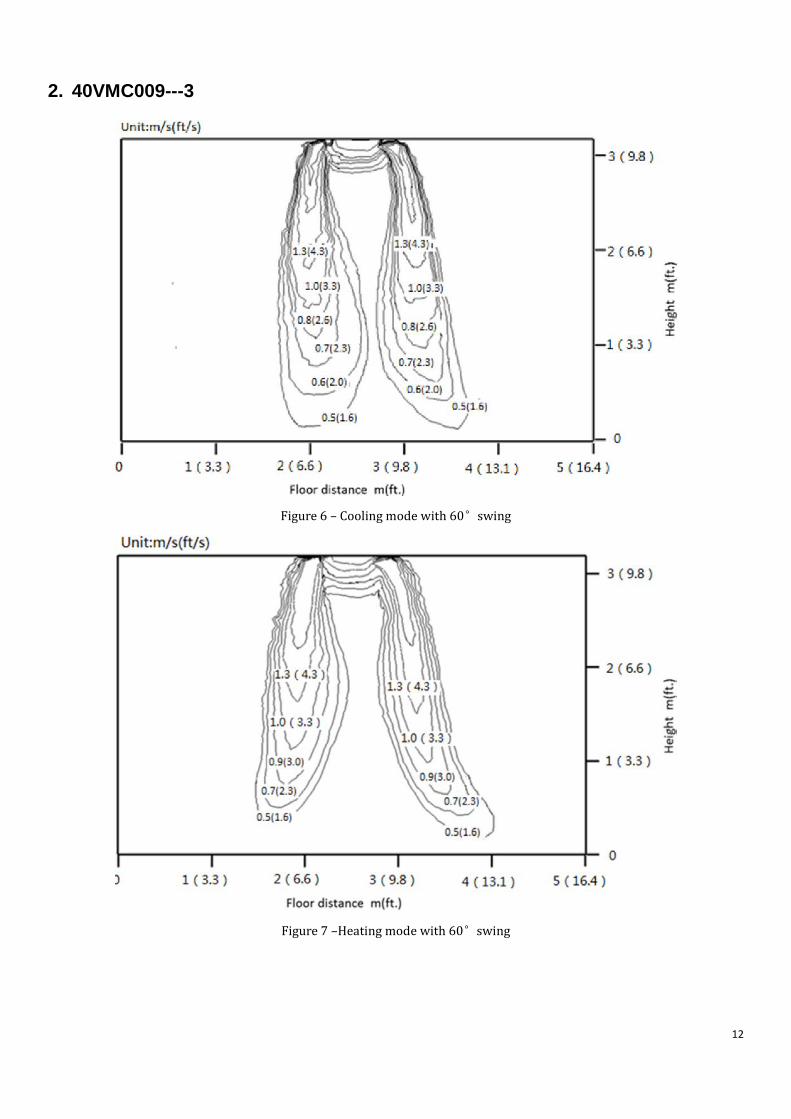
2. 40VMC009---3
Figure 6 – Cooling mode with 60°swing
Figure 7 –Heating mode with 60°swing
12

3. 40VMC012---3
Figure 8 – Cooling mode with 60°swing
Figure 9 –Heating mode with 60°swing
13
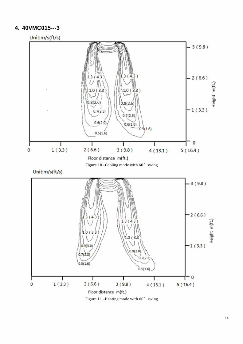
4. 40VMC015---3
Figure 10 –Cooling mode with 60°swing
Figure 11 –Heating mode with 60°swing
14

7. Sound Data
1. Sound Pressure Levels
Figure 12 – Overall Sound Levels
Table 14 – Cooling Mode Model H M L
40VMC007---3 40.1 38.2 34.3
40VMC009---3 40.1 38.2 34.3
40VMC012---3 45.5 42.1 38.1
40VMC015---3 45.5 42.1 38.1
Table 15 – Heating Mode Model H M L
40VMC007---3 40.4 38.5 34.7
40VMC009---3 40.4 38.5 34.7
40VMC012---3 45.4 42.3 37.6
40VMC015---3 45.4 42.3 37.6
NOTE: Units are dBA.
15

2. NC Curves NOTES: External Static Pressure: 0 in. (0 Pa) Power source: 208/230V-1Ph-60Hz
Figure 13 – 40VMC007---3 Figure 14 – 40VMC009---3
Figure 15 – 40VMC012---3 Figure 16 – 40VMC015---3
16

8. Capacity Data Tables Table 16 – Cooling Capacity
Model Unit Size
Indoor air temp.
68℉ DB / 57℉ WB
71℉ DB / 60℉ WB 75℉ DB / 63℉ WB 80℉ DB / 67℉ WB 85℉ DB / 71℉ WB 90℉ DB / 75℉ WB
TC SC TC SC TC SC TC SC TC SC TC SC
40VMC
7 4.11 4.11 4.98 4.98 5.84 5.56 7.00 6.10 7.46 6.32 7.93 6.52
9 5.28 5.28 6.40 5.68 7.51 6.29 8.00 6.93 9.60 7.14 10.19 7.32
12 7.04 6.67 8.53 7.15 10.02 7.93 12.00 8.75 12.79 8.99 13.59 9.19
15 6.67 7.54 10.66 8.18 12.52 9.10 15.00 10.10 15.99 10.32 16.98 10.49
Rated Condition: Evaporation temperature is 42.8°F with high speed airflow.
Table 17 – Heating Capacity
Model Unit Size
Indoor air temp.
62℉ DB 64℉ DB 67℉ DB 70℉ DB 73℉ DB 75℉ DB
TC TC TC TC TC TC
40VMC
7 8.32 8.21 8.11 8.00 7.46 7.11
9 10.40 10.27 10.13 10.00 9.33 8.88
12 13.52 13.35 13.17 13.00 12.13 11.55
15 17.68 17.46 17.23 17.00 15.86 15.10
Rated Condition: Condensation temperature is 114.8°F.
TC = Total capacity; KBTU/h SC = Sensible capacity; KBTU/h
17

Manufacturer reserves the right to discontinue, or change at any time, specifications or designs without notice and without incurring obligations. Catalog No. 17-40VMC001-03 Printed in U.S.A. Form 40VMC-1ED Pg 18 08-17 Replaces: NEW
Recommended