Energy- and exergy-based thermal analyses of a solar bakery unit
Iqra Ayub1 • Anjum Munir1 • Waseem Amjad1 • Abdul Ghafoor2 • Muhammad Salman Nasir3
Received: 27 March 2017 / Accepted: 4 March 2018� Akademiai Kiado, Budapest, Hungary 2018
AbstractThe use of solar concentrating technique for cooking purpose has beenwidely reported rather than for the baking processwhich
is rigidly precise and requires process controlled conditions. Secondly, the energy and exergy analyses are rarely made for the
baking process. In this paper, an energy- and exergy-based thermal analysis of an innovative solar bakery unit powered by
Scheffler reflector has been presented. The system comprised of primary reflector (Scheffler reflector), secondary reflector,
receiver and baking chamber. The baking experiments were conducted using four product samples (cakes) at 180 �C. Theentire bakery unit was divided into two main parts, i.e. fan–receiver and baking chamber to find out the inefficiencies of
bakery unit and its components. It was found that fan–receiver component handled major portion of solar energy and showed
energy losses. It possessed high improvement potential (IP) rate (0.153 kW), high exergetic factor (f) value (59.26%) and
low exergy efficiency (15%). Thermal analysis of baking process in the baking chamber showed variations in rate of
energy utilization, energy utilization ratio, exergy losses and exergy efficiency in range of 0.01–0.07 kW, 25–75%, 0.19–1.08
kW and 6.62–56.46%, respectively. The overall exergy efficiency of system was found to be 59.26%. The study provides a
detailed and sequential procedure to perform the thermal analysis of a solar concentrated technology-based bakery unit.
Keywords Solar baking � Thermal analysis � Scheffler reflector � Exergy
List of symbolsW Rate of energy utilization/kJ s-1
Qnet Net available energy/kJ s-1
T Temperature/�Cgr Receiver efficiency/%
ma Air flow rate/kg s-1
x Specific humidity/g of water kg of dry air-1
h Enthalpy/kJ kg-1
/ Relative humidity/%
v Air velocity/m s-1
Cp Specific heat/kJ kg-1 k-1
Qd Heat given by receiver to air as output/kW
QR Heat received by zigzag receiver/kW
Ib Beam radiations/W m-2
Ap Aperture area of Scheffler reflector/m2
Ac Surface area of Scheffler reflector/m2
d Solar declination
EUR Energy utilization ratio/%
Ex Exergy/kJ kg-1
Exr Exergy rate/kJ s-1
gEX Exergetic efficiency/%
f Exergetic factor/%
IP Improvement potential/kJ s-1
Introduction
Adaptation of new ways for thermal applications of
renewable energy resources has become important. Cook-
ing is one of the main energy application processes, and its
share of energy consumption is more in developing coun-
tries [1]. There is need to develop environment-friendly
new cooking and heating technologies due to rising envi-
ronmental issues with the use of fossil fuels and distur-
bance of ecological balance due to forest cutting. Being
freely and abundantly available, solar energy is a better
substitute all around the world. Various types of solar
collectors such as parabolic dish collector, parabolic trough
& Anjum Munir
1 Department of Energy Systems Engineering, University of
Agriculture Faisalabad, Faisalabad, Punjab, Pakistan
2 Department of Farm Machinery and Power, University of
Agriculture Faisalabad, Faisalabad, Punjab, Pakistan
3 Department of Structures and Environmental Engineering,
University of Agriculture Faisalabad, Faisalabad, Punjab,
Pakistan
123
Journal of Thermal Analysis and Calorimetryhttps://doi.org/10.1007/s10973-018-7165-3(0123456789().,-volV)(0123456789().,-volV)

collector and evacuated tube collector are designed and
used for cooking and heating purposes [2–6].
In case of baking, more heat is required than cooking to
complete the process effectively. The parabolic-type solar
concentrator is able to provide the required high operating
temperatures which are feasible for the process of baking,
but it requires two-dimensional solar tracking [7]. The
performance of a solar-based heating system depends on
the pattern of energy distribution. The design optimization
of a solar baking unit based on modelling of heat energy
distribution is always a challenging task due to complex
nature of baking process involving water evaporation, start
gelatinization, crust formation and browning reactions.
Therefore, a comprehensive thermal analysis of a system
becomes more important to perform. Presently, combina-
tion of energy and exergy analyses is getting importance
for the determination of systems performance in more
meaningful way [8]. In this regard, exergy analysis gives
more accurate information about the potential of a system
to extract heat from its surroundings [7]. Exergy-based
thermal analysis help to determine the factors for improv-
ing a thermal process and provides a much accurate
information about the effect of thermal process [9].
Various studies have been reported on the thermal
analysis of cooking processes, mainly focusing on energy
analysis. Nahar [10] developed a box-type solar cooker and
conducted its thermal performance using solar radiation
from the top surface and compared its performance with
simple solar oven and hot box solar cooker. The overall
efficiency of improved solar cooker was found to be 24.6%
[10]. In further study, he also performed energy analysis of
a solar cooker using different cover thicknesses of trans-
parent insulation material (TIM). The temperature obtained
was 158 �C using 40 mm TIM compare to 117 �C without
using TIM [11]. Algifri and Al-Towaie [12] reported
thermal analysis of a double glazed solar oven, taking
radiation from the top of its surface only. Maximum
improvement in efficiency was obtained by the addition of
a plane reflector and with proper orientation of cooker [12].
Nouni et al. [13] conducted energy analysis of three dif-
ferent box-type solar cookers to estimate energy output,
energy yield ratio, energy payback period and net energy
yield for possible their implications.
Energy and exergy analyses of solar cooker and baking
units based on vacuum tube collector have been presented
by many researchers. Sharma et al. [14] performed thermal
analysis of an evacuated tube collector-based solar cooker
using PCM as storage unit and obtained high temperature
of 130 �C, sufficient for 2-h cooking in the evening.
Singh et al. [15] investigated a solar cooker based on
parabolic trough collector using thermal oil. The amount of
heat stored was found to be increased by 19.45–30.38%
using PCM comparative to water [15]. Stumpf et al. [16]
integrated single- and double-stage heat pipe in flat plate
and vacuum tube collectors to meet cooking, baking, and
sterilization demand at small institutions. It was concluded
through thermal analysis that heat pipes are efficient means
of heat transport [16]. Kumar et al. [17] presented thermal
performance of evacuated tube collector-based solar pres-
sure cooker and developed a performance predictive model
under varying conditions. Harmim et al. [18] investigated a
box solar cooker with finned absorber and found it 7%
more efficient resulting in 12% decrease in time needed to
heat water comparative to conventional box-type solar
cooker. Richard [19] presented energy and exergy analyses
of a solar cooker, and distribution of energy, exergy and
respective efficiencies was calculated.
In order to get more heat energy for baking process,
solar concentrators are used in various forms and research
continues to make them more efficient. Thermal analyses
of solar cooker and baking systems based on concentrator
have also been reported by various researchers. Shukla
and Gupta [20] performed thermal analysis of a concen-
trating solar cooker and found an average efficiency,
optical losses, geometrical losses and thermal losses to be
14, 16, 30 and 35%, respectively. Panwar et al. [21] con-
ducted energy and exergy analysis of a parabolic solar
cooker, and variations in energy and exergy output were in
the range of 46.67–653.33 W and 7.37–46.46 W, respec-
tively. Pandey et al. [22] conducted an exergy analysis of
paraboloidal- and box-type solar cookers and found that
exergy efficiency of paraboloidal-type solar cooker was
higher than that of the box-type solar cooker. It was also
found that the exergy efficiency is directly proportional to
the volume of water increases [22]. Park et al. [23] pre-
sented an extensive review of energy and exergy analyses
of renewable energy systems like solar thermal, solar
photovoltaic and biomass cookstove. It was concluded that
energy analysis for the renewable energy systems has been
reported more than that of exergy analysis [23].
Zamani et al. [24] conducted a study on exergy analysis of
a double-exposure solar cooker using two similar solar
cookers with variable parabolic mirror position. After
experimentation, an innovative system with a variable
mirror on a parabolic curve was established, having aver-
age exergy efficiency of 30% [24]. Mbodji and Hajji [25]
presented a thermodynamic model of a parabolic solar
cooking system (PSCS) and conducted a comparison of the
model solution using two geometrical configurations
(dia. 9 depth 0.80 m 9 0.08 m and 1.40 m 9 0.16 m) of
a parabolic concentrator. Synthetic oil is used as a heat
storage fluid. The results showed that a 50 W m-2 increase
in the daily maximum solar radiation increases the storage
temperature by 4 �C and a 5% increase in the receiver
reflectance improves the maximum storage temperature by
3.6 and 3.9 �C, respectively [25]. Hassen et al. [26]
I. Ayub et al.
123
developed a baking system powered by solar energy using
thermal oil. Solar parabolic trough concentrator delivers
the heat to the oil which is then transferred to the baking
glass by convection and to baking pan (Injera stove) by
conduction lead to surface temperatures of 191 �C. A
system operated using thermal oil encounters with problem
of maintenances (leakages issues). Injera baking requires
high temperature, and it will become a more efficient stove
if it is attached with auto-trackers and heat storage mech-
anism [26]. Tesfay et al. [27] developed a new technology
of indirect solar stove for baking purpose comprising of a
parabolic dish having aperture area of 2.54 m2. It was
found that the heat losses at stagnation temperature of
system show that maximum loss of about 304.4 W be
encountered from receiver. The losses from stove and
pipeline were about 269.95 and 94.8 W, respectively. In
order to reduce these losses, system optimization is
required to improve the overall baking time for which
thermal analysis especially exergy aspect is important to
determine [27]. Sansaniwal et al. [28] presented the
research to summarize the previous findings on energy and
exergy analyses of different solar energy systems (solar
drying, solar air conditioning and refrigeration, solar water
heating, solar cooking and solar power generation through
solar photovoltaic and concentrated solar power techniques
used for various heat and power generation applications).
The main objective of that article was to bring out valuable
recommendations for wide exploitation of solar energy
systems for different applications, from a thermodynamics
perspective [28]. It has been noted that most of the studies
reported for the thermal analysis are about solar cooker and
mainly presenting only energy analysis as also reported by
Park et al. [23]. There is lack of such studies providing
exergy-based thermal analysis of a solar baking unit, and
no study has been found using fixed focused solar con-
centrator for baking purpose. Solar thermal applications for
cooking purposes have been reported by numerous
researchers but to get baking application through concen-
trating sun radiations has not been widely discussed.
Keeping in view the above-mentioned aspects, energy- and
exergy-based thermodynamic analysis of an innovative
solar bakery unit powered by Scheffler fixed focus con-
centrator has been performed. The available and utilized
solar energy was calculated using principles of energy
conservation. In order to calculate the efficiency of bakery
unit and its components separately, the entire system was
split into parts to conduct exergetic analysis. This study
provides an understanding of the significance of design
configurations on thermal efficiency and help to optimize
the thermal process for a baking unit based on Scheffler
reflector solar technology.
Materials and methods
Solar bakery unit
Figure 1 illustrates the designed solar bakery unit com-
prising of major parts, namely primary reflector, receiver,
secondary reflector, inner and outer chamber of the baking
unit. Solar radiations are concentrated using a primary
reflector (10 m2 Scheffler reflector). The edges of outer
chamber were joined prudently to assure that there is no
direct contact with the insulation material (rock wool),
which would affect the quality of the baking product. The
chamber was made of 0.8-mm-thick sheet of stainless steel
and comprised of an aligned zigzag receiver and pebbled
storage. This receiver was constructed from four pieces of
iron sheet having height and length of 330 and 2000 mm,
respectively, with a space of 30 mm between these two
sheets. The zigzag receiver was protected by a 3.8-mm-
thick tempered glass window, and it was cut into strips to
avoid the breaking of glass due to heat expansion. A DC
motor of 80 W (driven by a solar panel of 160 W) was
installed at the back side of the inner baking chamber
(60 9 60 9 60 cm3) to operate solar fan for the circulation
of air. The backside plate of the inner baking chamber was
made perforated (46%) for uniform airflow distribution
inside the baking chamber. A rectangular passage
(49.5 cm 9 8 cm) at the bottom of the baking chamber
served as an air outlet. Two perforated (17.4%) baking
trays were placed in the inner chamber to place the baking
products.
Concentrated solar radiations from the primary reflector
(Scheffler reflector) are intercepted by secondary reflector
that is further concentrated on the zigzag receiver of solar
bakery unit. The air gets warm while passing through the
receiver and a solar DC fan (80 W) provides draft for the
hot air movement from zigzag receiver to the baking
chamber. After exiting from the baking chamber, the air
partially transfers its remaining heat to the pebble bed
storage to store some thermal energy for 1–2 h of inde-
pendent baking. In case of fully loaded trays, as the process
continue, more vapour will be added to the air passing
through the baking chamber, and at one stage it could be
saturated, except if there is any by-pass for some fresh air.
Therefore, a narrow passage for fresh air is kept which can
be closed with a flap once the humidity does not rise.
A microcontroller (PIC18F252) was used to maintain
the inside temperature of baking chamber by controlling
fan power by employing a temperature sensor (PT-100) and
fan drive relay. Fan automatically turns off and on when
the desired temperature was achieved and below the set
value, respectively.
Energy- and exergy-based thermal analyses of a solar bakery unit
123

Baking experiments
Experiments were conducted to calculate the energy dis-
tribution at various points in the solar bakery unit. Before
to start, primary reflector was washed with water and left
for some time to dry the reflecting surfaces. After that
bakery unit was placed in front of primary reflector such
that the receiver faced the reflector. Pyranometer with
black pipe was installed at Scheffler reflector to record
beam radiation (Ib) in such a way that there would be no
shadow all around the pipe. K-type thermocouples linked
to a data logger were used to measure ambient air tem-
perature, air temperature at baking chamber inlet as well as
at outlet, temperature inside the baking chamber. In order
to measure the temperature distribution within the baking
chamber, the entire baking area was sectioned into three
zones vertically (each of 0.234 m wide and 0.64 m high).
From each section, four temperature measurements were
taken. The Kestrel 5000 Environmental meter (range
0.6–40 m s-1, resolution 0.1, accuracy ± 3%) was used to
measure the air velocity in the baking chamber before
putting the food samples. Its impeller was positioned per-
pendicular to the direction of flow of air coming inside the
chamber and was placed at various positions of inlet per-
forated plate inside the chamber to take an average value.
Four pans of cakes (each of 1 pound) were placed inside
the baking chamber. Ingredients for cake samples were
white flour, baking powder, sugar, eggs, vanilla essence,
butter and almonds. All these ingredients were mixed well
and then poured into an aluminium baking pan having the
size of six inches (diameter).
Thermal analysis of baking process
The receiver efficiency (ratio of energy output for the
baking unit to the total energy input at receiver) was
measured by using Eq. 1 [29].
gr ¼Qd
QR
ð1Þ
where gr is the receiver efficiency (%), Qd is the heat given
by receiver to air as output (kW) and Eq. 8 used for its
calculation, QR is the heat received by zigzag receiver
(kW) which was calculated using Eq. 2.
QR ¼ Ap:Ib
1000ð2Þ
where Ib is beam radiations (Wm-2) and Ap is the aperture
area of Scheffler Reflector (m2). The aperture area was
calculated using the following equation
Ap ¼ AcCos 43:23� d=2ð Þ ð3Þ
where Ac is the surface area of Scheffler reflector (m2) and
d is the solar declination.
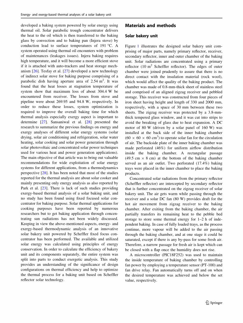
For the baking chamber, a schematic for energy and
mass balance analysis is shown in Fig. 2. The air heating
and moisturizing take place in baking process. The prin-
ciples of conservation of mass and energy can be applied to
model and analyse these processes [29].
Beam radiation
910mm 760mm
Photovoltaic
Latitudeangel ofthe site
tracking systems
Temperaturecontroller
Bakingchamber
Pebbles
680mm
540mm
Fan
Pyranometer
Concentratedradiations
ReceiverStand
B
Secondary reflector
Primary reflector 10m2
Telescopic clampmechanism
(a) (b)
Solar concentrator
Solar bakery unitSolar panel
Fig. 1 Scheffler reflector technology-based solar bakery unit: a CAD of the system, b physically developed system
I. Ayub et al.
123
Conservation of mass for incoming heated air
Mass flow at inlet = Mass flow at outletX
mi ¼X
mo ð4Þ
Subscripts i and o stand for inlet and outlet, respectively.
Mass conservation for moisture from the productX
miw þ mewð Þ ¼X
mow ð5Þ
The warm air entering the baking chamber possesses
some amount of moisture (iw) and moisture added to the
air during the baking process (ew). At the exit, the moisture
present in the air is represented by ow.
The small vent is kept open at the early stages of baking
process to let the exhaust air to go out, and it is recirculated
later on once the amount of moisture added from the pro-
duct is very low. It will happen in case of fully loaded
baking chamber with food items. During recirculation
when air passed through a warm bed of pebbles its tem-
perature and enthalpy increased, while specific and relative
humidity decreased up to some extent.
To express the energy conservation, the following
equation can be used [30].
Qnet �W ¼X
mo ho þV2o
2
� ��X
mi hi þV2i
2
� �ð6Þ
Air conditions in the bakery unit
During the baking process, the drying air conditions change
continuously due to heat and mass transfer mechanism.
Figure 3 shows a schematic of the solar bakery unit for the
thermal analysis of the baking process. The processes of
heating and humidification were defined for the entire
thermal analysis.
Air conditions across the receiver
Starting from point 1, the air properties at the inlet and
outlet of the receiver can be written as
xri [xro; Tri\Tro; hri hro; /rih i /ro ð7Þ
where the receiver inlet and outlet are denoted by ri and ro,
respectively.
The energy obtained by air while passing across the heat
receiver is given as
Q1�2 ¼ mcp T2 � T1ð Þ ð8Þ
Air conditions at the entrance of baking compartment
The air coming out of receiver acts as inlet air for the
baking chamber. The temperature of air at outlet of recei-
ver and inlet of baking chamber remains same so the air
conditions at both points (point 2 and point 3) are equal and
can be written as
xbci ¼ xro; Tbci ¼ Tro; hbci ¼ hro; /bci ¼ /ro ð9Þ
where baking chamber inlet and receiver outlet are repre-
sented by bci and ro, respectively.
During experiments, the measured values of air tem-
perature at inlet and outlet of baking chamber and receiver,
respectively, were found same showing that there was no
energy loss from point 2 to point 3 (due to good insulation
of the unit). The available heat at the inlet of baking
chamber can be calculated as
Baking chamber
Inlet air conditions
mi
ω i
hi
φ i
mo ωo ho φo
Outlet air conditions
Fig. 2 Energy balance of the baking chamber
PV moduleInsulation
Fan
Heated air
Receiver
1
2
5
4
3
Flap
By pass
Concentratedbeams from primary reflectorPebble
bed
Baking chamber
Dcmotor
Fig. 3 Schematic of the solar bakery unit illustrating change in air
conditions during the baking process at different places of the system.
(1) Inlet air for the receiver, (2) warm air from zigzag receiver, (3)
warm air entering the baking chamber, (4) outflow air, (5) recycled air
after passing through pebble bed
Energy- and exergy-based thermal analyses of a solar bakery unit
123

Qheat available ¼ mcp T3 � T1ð Þ ð10Þ
Air conditions at the exit of baking chamber
At the outlet of the bakery (point 4), the air conditions
are associated with the rate of energy used in baking
chamber and can be described as
xbci\xbco; Tbci [ Tbco; hbci [ hbco; /bci\ /bco
ð11Þ
where bci and bco are used to show baking chamber inlet
and outlet, respectively. At outlet, specific and relative
humidity would be more than at inlet while inverse in case
of temperature and enthalpy.
The temperature and enthalpy of outlet air increased,
while specific and relative humidity decreased up to some
extend when passed through a bed of pebbles (warm
structure due to heat absorbed from receiver via radiations).
These are the air conditions used as inlet for the receiver.
Mass conservation
Heating process
As the air passed though the receiver, its energy increased
and relative humidity decreased. The air mass balance
across a unit volume of receiver can be described as
m1 ¼ m2 ð12Þ
Based on Eq. 8, the air conditions at point 3 (baking
chamber inlet) and point 2 (receiver outlet) are same so the
humidity will also be same as
x2 ¼ x3 ð13Þ
Baking process
During baking process, moisture is added to the drying air
while some negligible amount of moisture was already in
inlet air. So, air exiting the baking chamber will possess
water content as summation of both mentioned above and
can be written as
mbcoxbco ¼ mbcixbci þ mbcinsidexbcinside ð14Þ
The subscript ‘‘bcinside’’ stands for the respective air
condition inside the baking chamber.
The effect of addition of the small amount of moisture
(due to less number of sample products to be baked) to the
air at the beginning of baking process is considered neg-
ligible as it passed through a bed of pebbles (warm struc-
ture due to heat absorbed from receiver via radiations).
Energy balance
Heating process
The bakery component, receiver is responsible for
imparting energy into coming air. The energy balance
equation across the receiver can be written as
Q1�2 or Qnet avaialble ¼ m2h2 � m1h1 or mrohro � mrihri
ð15Þ
The amount of energy transferred to the air while
passing across the receiver can also be calculated as
Q1�2 ¼ mcp T2 � T1ð Þ ð16Þ
This is available heat energy as described before in Eq. 10.
Baking process
During baking process, it is hard to use the full baking
capability of air. So, the unused energy at outlet is normally
guided to recirculate and it is expressed as
Qwasted=recirculated m4h4ð Þ ¼ Qnet available � QEnergy utilized
ð17Þ
The energy at the outlet is stored in pebble bed to store
heat.
The amount of energy utilized in the baking chamber
can be written as
Q3�4 ¼ mcp T3 � T4ð Þ ð18Þ
Based on Eqs. 16 and 18, energy utilization ratio (EUR)
of the baking chamber is given as [31].
EUR ¼ heat utilized
heat supplied¼
CpiTi � CpoTo� �
CpiTi � CpaTa� � ð19Þ
Exergy analysis
In recent years, the exergy concept has been widely used in
thermal processes for system optimization. This analysis
provides a more realistic understanding between energy
losses to the environment and internal irreversibility in the
process. For exergy analysis, a general form equation was
used [32].
Exergy ¼ cpda T � Tað Þ � Ta lnT
Ta
� �ð20Þ
The subscript a stands for ambient condition.
I. Ayub et al.
123

Heating process
Exergy inflow and outflow can be determined by incor-
porating the respective values of temperatures in
Eq. 20. During the heating process exergy inflow at the
inlet of baking chamber can be written as
Exbci ¼ cpda Tbci � Tað Þ � Ta lnTbci
Ta
� �ð21Þ
Baking process
In the baking chamber, exergy losses take place. The
exergy outflow of baking chamber can be written as
Exbco ¼ cpda Tbco � Tað Þ � Ta lnTbco
Ta
� �ð22Þ
Then, exergy loss can be calculated from Eqs. 21 and 22
as
Exergy loss ¼ Exergy inflow � Exergy outflow ð23Þ
Using the calculated values of exergy loss and exergy
inflow, exergy efficiency can be calculated as below [32].
Exergetic efficiency gExð Þ ¼ 1� ExL
Exið24Þ
In order to perform exergy analysis of the solar bakery,
the system is categorized into two major parts, fan–receiver
combination (A) and baking chamber (B) as shown in
Fig. 4.
For each component of the bakery unit, exergy inflow
and outflow were calculated using Eq. 21 by using the
respective temperature values. To determine the compara-
tive inefficiencies of the components based on exergy
analysis, three parameters (exergy efficiency; improvement
potential rate, IP; exergetic factor, f) were selected to cal-
culate. More the value of IP for a component deduces the
possible improvement in that component to increase sys-
tem efficiency. Similarly, higher exergetic factor of a
component means higher amount of energy is used by that
component. The basic equations used for exergy analysis
are tabulated in Table 1.
Error analysis
During an experiment, errors and uncertainties are
inevitable in the measured values depending upon the
accuracy of the instrument used. The instrument selection,
calibration and way to handle the devises are main reasons
of errors. It therefore becomes mandatory to perform a
detailed uncertainty analysis for the experimental measured
and calculated values. Using the concept of the dimen-
sionless relative error in the individual factors denoted by
xn, the errors in the concerned parameters were calculated
as shown in Table 2 using the following equation [33].
U ¼ x1ð Þ2 þ x2ð Þ2 þ � � � þ xnð Þ2h i1=2
ð29Þ
Result and discussion
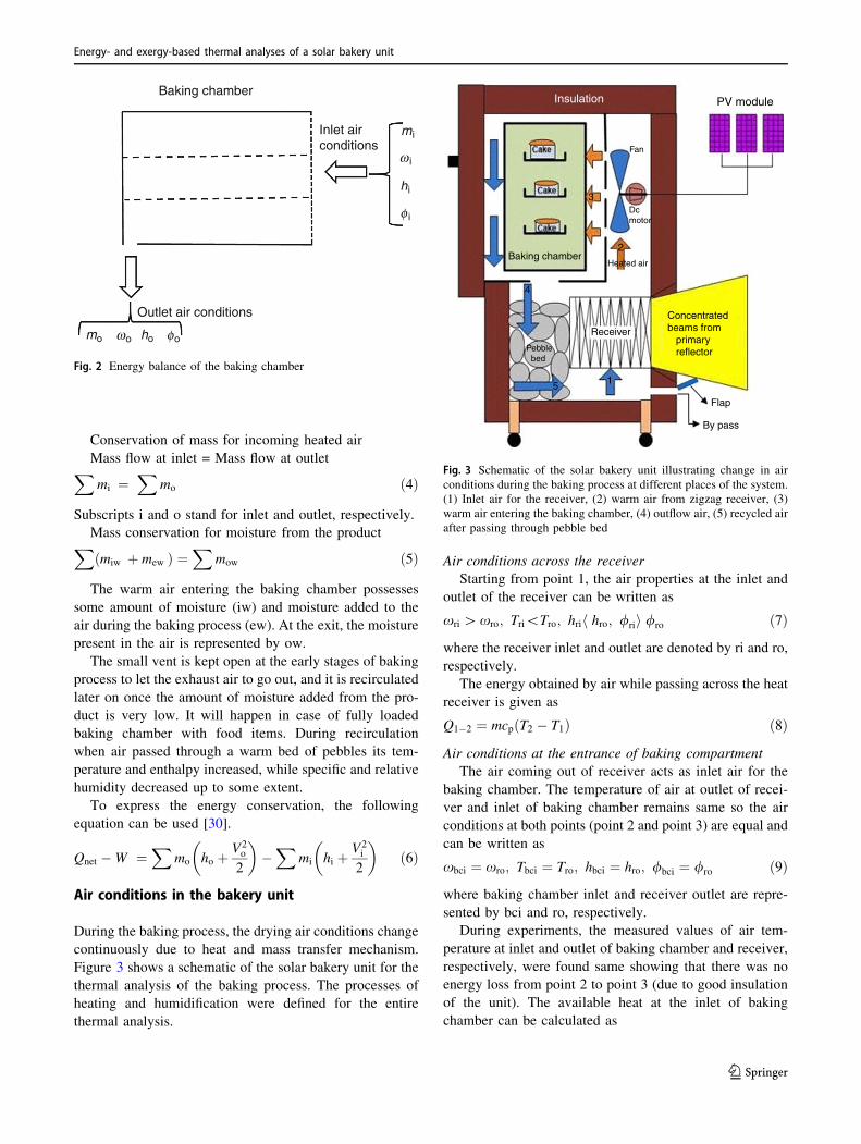
Air temperature at various sections of the baking chamber
was also measured (Sect. 2.2). Figure 5 shows experi-
mental measured temperature distribution pattern within
the baking chamber. A uniform temperature distribution
can be observed because of uniform air flow within the
baking chamber (Fig. 5). The average temperature in the
baking chamber was approximately 180 �C. This unifor-
mity facilitates a uniform baking process and ultimately
produces a product of uniform quality measures.
Energy
Figure 6 shows the rate of energy utilization with respect to
baking time during the baking process. It can be observed
that more energy was consumed at the early stages of the
baking process due to more mixture (loosely bounded
surface moisture) of cake ingredients. After certain period
of time, the rate of energy utilization decreased due to
crusty and hardened layer of baking samples, creating
resistance for the penetration of heat into the product. In a
baking process, product quality to be maintained is always
a challenging task, and it mainly depends upon temperature
inside the baking chamber. Beside the importance of
temperature selection for the baking process, its uniform
B: Baking chamber
A: Fan-receiver
2
3
4
1
Fig. 4 Schematic of the solar bakery components for the exergy
analysis
Energy- and exergy-based thermal analyses of a solar bakery unit
123
distribution significantly affects the rate of energy utiliza-
tion. Non-uniform heating inside the baking chamber
causes variation in colour and moisture contents which can
be reduced with better design and optimum operating
conditions. The warm air was introduced uniformly inside
the baking chamber employing a perforated plate which
resulted in uniform baking rate for all the baking samples
(04 cakes). The heat transferred from air to cake surface
and from surface to inside the cake occurred with con-
vection and conduction modes of heat transfer, respec-
tively. So, the fact of over- and under-baking was also
reduced, important to control the rate of energy utilization.
Similarly, the calculated results for energy utilization
ratio (EUR) are shown in Fig. 7. It can be clearly observed
that EUR is directly proportional to the rate of energy
consumed as shown in Fig. 7. During the entire baking
process, the EUR decreased from 78 to 24%. The EUR
depends upon the sample layer thickness, type of material,
area exposed to warm air and baking conditions. These
factors are important in controlling the internal and exter-
nal resistant to heat and mass transfer in the baking pro-
cess. Internal resistance depends upon the mass diffusion
process, while external resistance depends upon the surface
convective mass transfer. So rate of energy utilization will
also vary depending upon the nature (chemistry) of the
product to be baked.
Figure 8 shows the comparative view of the energy
efficiencies at various phases of energy flow in the systems.
Table 1 Mathematical relations
used for exergy analysisExergetic efficiency gEx ¼ EXr2�EXr1
PFan�Receiver� 100 (Fan–receiver) (25)
gEx ¼ EXr4
EXr3� 100 (Baking chamber) (26)
Improvement potential rate IP ¼ 1� gð Þ EXi � EXoð Þ (27)
Exergetic factor f ¼ EXi;k
EXi;t� 100 (28)
Table 2 Error of uncertainty for
the measured and calculated
parameters
Parameter measured/calculated Unit Value
Baking chamber inlet temperature �C ± 0.07
Baking chamber inside temperature �C ± 0.02
Baking chamber outlet temperature �C ± 0.08
Temperature before the receiver �C ± 0.08
Ambient temperature �C ± 0.15
Total uncertainty for energy at Scheffler reflector kJ s-1 ± 0.52%
Total uncertainty for energy at receiver kJ s-1 ± 1.49%
Total uncertainty for supplied energy kJ s-1 ± 1.92%
Total uncertainty for energy utilization kJ s-1 ± 2.03%
183
182
181
180 179.5179.87 179.75
179
178
177
176
175
1741 2 3
179 181
179
179.5
179
179.87
Section of baking chamber
Tem
pera
ture
/°C
180
178
180
181
179.75
181
180
178
179.5
Point 1
Point 2
Point 3
Point 4
Average
Fig. 5 Temperature distribution
at various sections of the baking
chamber
I. Ayub et al.
123

Based on data recording and calculation, it can be observed
that energy efficiency of receiver (ratio of the energy
available at receiver to the reflector, Eq. 1) increased from
37 to 65% due to increase in temperature at secondary
reflector (glass window of the receiver). As the focus of
Scheffler reflector is set to the secondary reflector, the
temperature of the receiver increased causing increase its
efficiency. After that heat transfer from receiver to air
depends upon the temperature difference of air and recei-
ver. The energy transfer efficiency (ratio of heat given to
air to heat available at receiver) increased for the first half
hour of baking time and then started to decline due to low
heat transfer rate to the already warm recirculated air. The
energy utilization ratio in the baking chamber was
observed higher at the early stages of baking process due to
more heat transfer to the products and decreased later on. It
can be seen that the difference between the receiver energy
transfer efficiency and energy utilization efficiency
increased after point 1 (marked at graph), which shows the
unused amount of heat available in the incoming air and
could be taken as loss of heat. This difference can be
reduced by putting more cake samples into the baking
chamber. Secondly the difference between the receiver
efficiency and receiver energy transfer efficiency increased
after point 2 (marked at graph). This difference can also be
considered as loss of heat.
Furthermore, heat losses across the walls of the baking
chamber (all sides excluding the air inlet perforated side)
were calculated using Fourier’s law of heat conduction.
Insides of the baking chamber were considered isothermal
to obtain a general relation for heat conduction
Q ¼ �kADTL
where k is the thermal conductivity of the material (for
stainless steel: 12–45 W m-1 K-1), DT is the temperature
difference, A is the cross-sectional area of a wall inside of
baking chamber (0.6 m 9 0.6 m), and L is the wall/side
thickness.
There are four walls/sides of the baking chamber (front,
left and right to the air inlet side and top of chamber). The
losses from the bottom side remain inside the system, i.e.
cause addition of heat to pebbles. The thermal conductivity
of a material, in general, varies with temperature. But
sufficiently accurate results can be obtained by using a
constant value for thermal conductivity at the average
temperature. Thickness of each side of wall comprises of
6 mm rockwool sandwiched into 0.8-mm stainless steel
sheets. Due to good insulation property of rockwool, the
calculated losses were found 10–13% of heat available
inside the baking chamber.
0.08
0.06
0.04
0.02
0.000 5 10 15
Baking time/min
Ene
rgy
utili
zatio
n/kW
20 25 30 35
Fig. 6 Rate of energy utilization during the baking process in the
baking chamber
0 5 10 15
Baking time/min
20 25 30 35
80
60
40
20
0
Ene
rgy
utili
zatio
n ra
tio
Fig. 7 Change in EUR with baking time
020
30
40
50
60
701
2
80
5 10
Reflector-receiver (receiver efficiency)Receiver-air (energy transfer efficiency)Heated air-sample products (EUR)
15
Baking time/min
Ene
rgy
effic
ienc
y/%
20 25 30 35 40
Fig. 8 Energy efficiencies at various phases of energy flow in the
systems
Energy- and exergy-based thermal analyses of a solar bakery unit
123

Exergy analysis
Baking chamber
Figure 9 shows the exergy loss (energy destruction) in the
baking chamber which decreased as baking time pro-
ceeded. The potential of a unit mass of warm air to perform
heat and mass transfer mechanisms decreased with baking
time. This can be understood keeping in view the same
reasons as explained for the energy utilization. Hence,
exergy loss is directly proportional to the energy utilization
and both are influenced by baking temperature, product
type and airflow rate. The higher and lower values of
exergy losses were found to be 1.1 and 0.01 kJ kg-1,
respectively.
As baking process proceeded to its completion phase,
the rate of exergy loss decreased which ultimately caused
the rise of exergetic efficiency based on Eq. 24 as shown in
Fig. 10. The calculated values of exergy inflow, outflow
and exergy loss were used to present the variation of the
exergetic efficiency (which is increased with baking time).
It could be explained with the fact that available energy in
the baking chamber increased with time due to less energy
utilization rate. It means that exergy loss would decrease,
while exergy inflow to the baking chamber will be
increased resulting in an increase in exergy efficiency.
Entire baking system
The outcomes of exergetic analysis for solar bakery unit
are tabulated in Table 3. Based on the performance
parameter (Table 1), the fan–receiver component of the
bakery unit was found to handle major part of the energy
than that of the baking chamber. It can be noted that this
component possessed higher values of exergetic factor and
improvement potential rate while lower value of exergetic
efficiency than that of the baking chamber. Therefore, there
should be some improvement in this component (fan–re-
ceiver) of the bakery unit. From the combination of fan–
receiver, the receiver’s lower efficiency caused loss of
energy. The receiver remained unable to harvest all the
incident energy from the primary reflector. The modifica-
tions in the receiver area and secondary reflector are need
to be done. During the baking experiments under the dif-
ferent baking temperatures, no significant change in the
values of improvement potential was found indicating the
goodness of insulation of bakery unit [34].
Table 4 presents some of the most relevant studies
about energy and exergy analyses of solar-based cookers
to make a comparative assessment of the results.
Although there are many parameters affecting the out-
comes of each system under consideration like design
configuration, products to be processed, capacity of the
unit, airflow rate, the current study showed quite satis-
factory outcomes based on the parameters listed in
Table 4. As the bakery is powered with Scheffler solar
reflector technology, it is better to compare its results with
that system operated through the same technology. In this
regard, Kumar et al. [36] reported a Scheffler community-
type cooker (8.21 m2) for heating of 20 kg water, and
maximum exergy obtained was reported of 0.055 kW. To
make a comparative statement, there is about 50% more
exergy (1.08 kW) obtained with the current study using a
Scheffler reflector of an area of 10 m2.
Experimental and predicted results
The energetic (energy utilization and EUR) and exergetic
(exergy loss and exergy efficiency) parameters based on
experimental data were modelled with respect to baking
time. All the parameters were found best fitted in
00.0
0.2
0.4
0.6
0.8
1.0
1.2
5 10 15
Baking time/min
Exe
rgy
loss
/kJ
kg–1
20 25 30 35 40
Fig. 9 Loss of exergy (energy destruction) during the baking process
00
10
20
30
40
50
60
5 10 15
Baking time/min
Exe
rget
ic e
ffici
ency
/%
20 25 30 35 40
Fig. 10 Exergetic efficiency of baking process
I. Ayub et al.
123

polynomial cubic models using sigma plot 12. The values
for all the constants of a basic polynomial Eq. 29 are
tabulated in Table 5.
y ¼ yo þ axþ bx2 þ cx3 ð30Þ
Figure 11 shows the comparative trend of energy
(Fig. 11a: energy utilization, Fig. 11b: energy utilization
ratio) and exergy (Fig. 11c: exergy loss, Fig. 11d: exergy
efficiency) parameters, and it can be observed that a good
agreement was found between model predicted and
experimental measured parameters. These developed rela-
tionships can be used for the optimal design of bakery unit
to make it more energy efficient.
Conclusions
Energy- and exergy-based thermodynamic analysis of an
innovative baking system powered by Scheffler fixed focus
solar concentrator was performed. The energy and exergy
efficiencies of solar bakery were calculated based on
energy distributions at its components. The receiver energy
efficiency increased with baking time (37–65%). Four
samples of cakes each of 1 pound consumed energy at the
rate of 0.01–0.07 kW with an energy efficiency of 25–75%
in the baking chamber. The rate of energy utilization and
exergy loss (energy destruction) decreased with baking
time. Based on the performance parameters in exergy
analysis, it was found that system component fan–receiver
dealt with major part of solar energy coming from primary
reflector as that component possessed high improvement
potential (IP) rate (0.153 kW), high exergetic factor
(f) value (59.26%) and low exergy efficiency (15%). The
receiver remained unable to harvest and transmit that
energy to air at full extent (Fig. 8). Therefore, energy
efficiency of system could be increased by improving
design configuration of that part. The overall exergy effi-
ciency of system was found to be 59.26%. As the baking
process discontinued, the exergy losses were minimized
while the exergy efficiency became higher at that point.
Table 3 Outcomes from exergetic analysis of bakery unit
Component Exergy
inflow/kJ s-1Exergy
outflow/kJ s-1Exergy
loss/kJ s-1Exergetic
efficiency/%
Improvement
potential/kJ s-1Exergetic
factor/%
Fan–receiver (A) 0.48 0.30 0.18 15.00 0.153 59.26
Baking chamber (B) 0.33 0.18 0.15 54.55 0.068 40.74
Overall system (A–B) 0.81 0.48 1.29 59.26 0.134 100.0
Table 4 Comparison of solar cookers with respect to energy and exergy analysis
Cooker type Energy
efficiency/%
Exergy
efficiency/%
Energy out of
system/utilized/kW
Exergy out/loss/
kW
References
Domestic size parabolic
solar cooker
46.82 32.97 0.046–0.653 0.00–0.046.46 Panwar et al. [21]
Box-type solar cookers 3.05–35.2 2.79–15.65 0.0082–0.061 0.0014–0.0061 Ozturk [35]
Parabolic-type solar cooker 0.58–3.52 0.4–1.25 0.021–0.73 0.0029–0.0066
Solar bakery unit 25–75 6.62–56.46 0.01–0.07 0.19–1.08 Present study
Forced convection solar air
heater (FCSAH)
0.09–0.75 0.08–0.31 Kumar et al. [6]
0.07–0.42 0.06–0.17
Table 5 Values for all the
constants of a basic polynomial
equation
Parameter yo a b c R2
Energy utilization/kJ s-1 0.078 - 0.0019 - 0.0001 2.776E-6 0.9945
Energy utilization ratio/EUR 81.96 - 0.952 - 0.0989 0.0023 0.9976
Exergy loss/kJ kg-1 1.593 - 0.1095 0.0021 - 7.270E-6 0.9983
Exergy efficiency/% 8.773 - 1.3272 0.2057 - 0.0037 0.9961
Energy- and exergy-based thermal analyses of a solar bakery unit
123

Overall, the system gave quite good results in terms of
baking process time, baking quality (good appearance) and
energy utilization rate, and this could be increased further
by optimization and controlling of baking conditions.
Consequently, it is suggested that receiver size, airflow
rate, number of food samples and moisture content should
be taken into consideration for the efficient use of energy to
minimize the energy losses.
Acknowledgements The authors wish to acknowledge the Depart-
ment of Energy Systems Engineering, University of Agriculture
Faisalabad, Pakistan, and International Centre for Development and
Decent Work (ICDD), Germany, for the financial support.
References
1. Pohekar SD, Kumar D, Ramachandran M. Dissemination of
cooking energy alternatives in India—a review. Renew Sustain
Energy. 2005;9:379–93.
2. Essen M. Thermal performance of a solar cooker integrated
vacuum-tube collector with heat pipes containing different
refrigerants. Sol Energy. 2004;76:751–7.
3. Terres H, Ortega JA, Gordon M, Morales JR, Lizard A. Heating
of bee honey, olive oil, milk and water in a solar box type with
internal reflectors. In: Energy sustainability conference, Long
Beach, California, USA; 27–30 June 2007.
4. Hussein HMS, El-Ghetany HH, Nada SA. Experimental investi-
gation of novel indirect solar cooker with indoor PCM thermal
storage and cooking unit. Energy Convers Manag. 2008;49:
2237–46.
5. Meibodi SS, Kianifar A, Mahian O, Wongwises S. Second law
analysis of a nano-fluid-based solar collector using experimental
data. J Therm Anal Calorim. 2016;126:617–26.
6. Kumar RA, Babu BG, Mohanraj M. Thermodynamic perfor-
mance of forced convection solar air heaters using pin–fin
absorber plate packed with latent heat storage materials. J Therm
Anal Calorim. 2016;126:1657–78.
7. Farooqui SZ. A review of vacuum tube based solar cookers with
the experimental determination of energy and exergy efficiencies
of a single vacuum tube based prototype. Renew Sustain Energy
Rev. 2014;31:439–45.
8. Rabha DK, Muthukumar P, Somayaji C. Energy and exergy
analyses of the solar drying processes of ghost chilli pepper and
ginger. Renew Energy. 2017;105:764–73.
0 5 10 15
Baking time/min
Ene
rgy
utili
zatio
n/kW
Exe
rgy
loss
/kJ
kg–1
Ene
rgy
utili
zatio
n ra
tioE
xerg
etic
effi
cien
ty/%
20 25
ExperimentalPredicted
ExperimentalPredicted
30 35 40
1.2
1.0
0.4
0.2
0.0
0.6
0.8
0.08
0.07
0.05
0.06
0.04
0.03
0.02
0.01
0.000 5 10 15
Baking time/min20 25 30 35 40
0
20
40
60
80
0 5 10 15
Baking time/min20 25 30 35 40
ExperimentalPredicted
0 5 10 15
Baking time/min20 25 30 35 40
0
10
30
20
40
50
60
ExperimentalPredicted
(a) (b)
(c) (d)
Fig. 11 Experimental and model predicted energetic and exergetic parameters: a rate of energy utilization, b EUR, c exergy loss, d exergy
efficiency
I. Ayub et al.
123
9. Sogut Z, Ilten N, Oktay Z. Energetic and exergetic performance
evaluation of the quadruple-effect evaporator unit in tomato paste
production. Energy. 2010. https://doi.org/10.1016/j.energy.2010.
05.035.
10. Nahar NM. Performance and testing of an improved hot box solar
cooker. Energy Convers Manag. 1990;30:9–16.
11. Nahar M. Studies on a hot box solar cooker with transparent
insulation material. Energy Convers Manag. 1994;9:787–91.
12. Algifri H, Al-Towaie HA. Efficient orientation impacts of box-
type solar cooker on the cooker performance. Sol Energy.
2001;70:165–70.
13. Nouni MR, Mullick SC, Kandpal TC. An energy analysis of box-
type solar cooker utilization in India. Int J Ambient Energy.
2008;29(1):45–56.
14. Sharma SD, Iwata T, Kitano H, Sagara K. Thermal performance
of a solar cooker based on an evacuated tube solar collector with
a PCM storage unit. Sol Energy. 2005;78:416–26.
15. Singh H, Saini K, Yadav A. Experimental investigation of the
solar cooker during sunshine and off-sunshine hours using the
thermal energy storage unit based on a parabolic trough collector.
Int J Ambient Energy. 2016. https://doi.org/10.1080/01430750.
2015.1023836.
16. Stumpf P, Balzar A, Eisenmann W, Wendt S, Ackermann H,
Vagen K. Comparative measurements and theoretical modelling
of single-and double-stage heat pipe coupled solar cooking sys-
tems for high temperatures. Sol Energy. 2001;71(1):1–10.
17. Kumar R, Adhikari RS, Garg HP, Kumar A. Thermal perfor-
mance of a pressure cooker based on evacuated tube solar col-
lector. Appl Therm Eng. 2001;21:1699–706.
18. Harmim A. Experimental investigation of a box-type solar cooker
with a finned absorber plate. Energy. 2010;35(3):799–802.
19. Richard P. Exergy analysis of the solar cylindrical-parabolic
cooker. Sol Energy. 2005;79:221–33.
20. Shukla SK, Gupta SK. Performance evaluation of concentrating
solar cooker under Indian climatic conditions. In: Second inter-
national conference on energy sustainability, Jacksonville, Flor-
ida, USA; 10–14 August 2008.
21. Panwar NL, Kaushik SC, Surendra K. Experimental investigation
of energy and exergy efficiencies of domestic size parabolic dish
solar cooker. J Renew Sustain Energy. 2012. https://doi.org/10.
1063/1.3699615.
22. Pandey AK, Tyagi VV, Park SR, Tyagi SK. Comparative
experimental study of solar cookers using exergy analysis.
J Therm Anal Calorim. 2012;109:425–31.
23. Park SR, Pandey AK, Tyagi VV, Tyagi SK. Energy and exergy
analysis of typical renewable energy systems. Renew Sustain
Energy Rev. 2014;30:105–23.
24. Zamani H, Mahian O, Rashidi I, Lorenzini G, Wongwises S.
Exergy optimization of a double exposure solar cooker by
response surface method. J Therm Sci Eng Appl. 2017;9:011003-
1. https://doi.org/10.1115/1.4034340.
25. Mbodji N, Hajji A. Modelling, testing and parametric analysis of
a parabolic solar cooking system with heat storage for indoor
cooking. J Energy Sustain Soc. 2017;7:32. https://doi.org/10.
1186/s13705-017-0134-z.
26. Hassen A, Kebedy SB, Wihib NM. Design and manufacturing of
thermal energy based Injeria baking glass pan. Energy Procedia.
2016;93:153–9.
27. Tesfay AH, Kahsay MB, Nadal OJ. Design and development of
solar thermal injeria baking; steam based direct baking. Energy
Procedia. 2013;57:2946–55.
28. Sansaniwal SK, Sharma V, Mathur J. Energy and exergy analyses
of various typical solar energy applications: a comprehensive
review. J Sustain Energy Rev. 2017. https://doi.org/10.1016/j.
rser.2017.07.003.
29. Schirmer P, Janjai S, Esper A, Smitabhindu R, Muhlbaur W.
Experimental investigation of the performance of the solar tunnel
dryer for drying Bananas. Renew Energy. 1996;7:119–29.
30. Midilli A, Kucuk H. Energy and exergy analyses of solar drying
process of pistachio. Energy. 2003;28:539–56.
31. Mujumdar AS. Hand book of industrial drawing. 2nd ed. New
York: Marcel Dekker; 1995.
32. Amjad W, Hensel O, Munir A, Esper A, Sturm B. Thermody-
namic analysis of drying process in a diagonal-batch dryer
developed for batch uniformity using potato slices. J Food Eng.
2016;169:238–49.
33. Holman JP. Experimental methods for engineers. 6th ed. Singa-
pore: McGraw-Hill; 1994 (International ed.).34. Erbay Z, Icier F. Energy and exergy analyses on drying of olive
leaves (Olea europaea) in tray drier. J Food Process Eng.
2011;34(6):2105–23.
35. Ozturk HH. Comparison of energy and exergy efficiency for solar
box and parabolic cookers. J Energy Eng. 2007;133(1):53–62.
36. Kumar N, Vishwanath G, Gupta A. An exergy based unified test
protocol for solar cookers of different geometries. In: World
Renewable Energy Congress 2011 Sweden, Solar Thermal
Applications, 2011; p. 3741–8.
Energy- and exergy-based thermal analyses of a solar bakery unit
123
Recommended