® Specif icat ion Submittal page
Job Name:
Job Number:
Model Numbers:
Energi Savr NodeTM QSN 0-10 V/Softswitch® Fixture Controllers
369-241f 1 01.16.12Energi Savr NodeTM for 0-10 V Energi Savr NodeTM with Softswitch®
The Energi Savr NodeT (ESN) family is a group of modular products for the control of lighting and other loads. This document describes the following products:
•ESN unit for 0-10 V (models QSN-4T16-S and QSN-4T16-S-347 — 0-10 V Control / SoftswitchR)
•SoftswitchR ESN unit (models QSN-4S16-S and QSN-4S16-S-347 — SoftswitchR)
Features•Defaultconfigurationrequiresnocommissioning.•ProgrammingusingintegralinterfaceontheESN unit.•Fouroccupancysensorinputsforautomatedcontrolof
lights in 4 zones.•Fourdaylightsensorinputsautomaticallyadjustlight
levels based on the amount of natural light entering through the windows.
•FourIRreceiverinputsforpersonalcontrol.•FourinputsforIECPELV/NEC® Class 2 dry contact
switches.•IncludesQScontrollinkforseamlessintegrationoflights,controlstations,andQSsensormodules.
•SoftswitchRtechnologyyields1,000,000cyclerelaylifetime.
•ContactLutronforcompatibilitywithQuantum® System.
System Example
QSlink
ControlPower120-277 V~
4LoadInputFeeds
120-277 V~;347 V~3
4 0-10 V Channels(QSN-4T16-S and QSN-4T16-S-347)
Emergency Contact Closure
Input
Contact Closure Input
4SwitchedLoadOutputs(16 A Softswitch® 120-277 V~;347 V~3)
Wireless Communication
WiredDaylight Sensors (up to 4)2
Wired Daylight Sensors (up to 4)1,2
WiredOccupancy Sensors (up to 4)
Wired Occupancy Sensors (up to 4)1
Wired Wallstation orIRreceivers(upto4)
Wired Wallstation orIRReceivers (up to 4)1
IECPELV/ NECR Class 2 DryContactSwitch (up to 4) (by others)
IRTransmitter
IRTransmitterOR OR
OR OR
Notes: 1 Up to 4 wired sensors total (of any type).2 The maximum number of daylight sensors (wired and
wireless) that an ESN unit can support is four (1 per zone).
3 For347V~ models only.
QSMseeTouch® QS Wallstation
ESN Programming
Interface
RadioPowrSavrTM Occupancy Sensor (up to 10 per QSM)
RadioPowrSavrTM DaylightSensor (up to 10 per QSM)2
Pico® Wireless Controller (up to 10 per QSM)
® Specif icat ion Submittal page
Job Name:
Job Number:
Model Numbers:
Energi Savr NodeTM QSN 0-10 V/Softswitch® Fixture Controllers
369-241f 2 01.16.12
Specifications
Power•ControlPower:120V~; 220-240 V~; 277 V~ 50/60 Hz•LightningstrikeprotectionmeetsANSI/IEEEstandard
62.41-1991. Can withstand voltage surges of up to 6000 V~ and current surges of up to 3000 A
•Currentdraw:0.5Amax•10-yearpowerfailurememory:restoreslightingtolevels
prior to power interruption•Latchingrelayskeeppreviouslyilluminatedzoneson
when control power feed is lost
Standards•ULListed•CSA•LutronQualitySystemsregisteredtoISO9001:2008
Environment•AmbientTemperatureOperatingRange:32ºFto104ºF(0ºCto40ºC)
•Relativehumidity:lessthan90%non-condensing•Forindooruseonly•MeetsNEC®requirementsforinstallationin“otherspace
used for environmental air”
Terminal Wiring•ControlPowerWiring:14AWGto12AWG(2.5mm2 to
4.0 mm2)•LoadWiring:14AWGto12AWG(2.5mm2 to 4.0 mm2)•0-10VWiring:20AWGto12AWG(0.5mm2 to 4.0 mm2)•InputGroupWiring:20AWGto12AWG(0.5mm2 to
4.0 mm2) — maximum wire run length to each input not to exceed 150 ft (46 m)
•QSLinkWiring:22AWGto12AWG(0.5mm2 to 4.0 mm2)•ContactClosureWiring:20AWGto12AWG(0.5mm2 to
4.0 mm2)
Physical Design and Mounting•NEMAType1,IP-20protection•Surfacemount
Load Types (relay ratings)•16ATungsten,120to277V~•16AACGeneralUse,120to277V~•16AElectricDischargeLamp(ballast),120to277V~,
347 V~ (347 V~ models only)•16AInductive,120to277V~•0.5HP,120V~•1.5HP,220to277V~
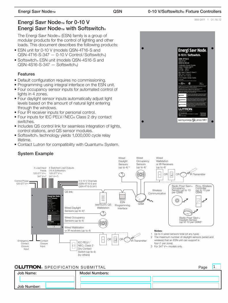
Input Default Associations
Inputs/Outputs Zone 1 Zone 2 Zone 3 Zone 4
Gro
up 1
Occ X
Photo X
IR X
Switch X
Gro
up 2
Occ X
Photo X
IR X
Switch X
Gro
up 3
Occ X
Photo X
IR X
Switch X
Gro
up 4
Occ X
Photo X
IR X
Switch X
CCI X X X X
EmergencyCCI X X X X
Softswitch® — 120 V~ to 277 V~, 347 V~ (347 V~ models only)
•SoftswitchR relay is rated for 16 A continuous use perchannel,whichisthemaximumcontinuousloadfora20AOvercurrentProtectionDevice(BranchBreaker).
•PatentedSoftswitchR circuit eliminates arcing at mechanical contacts when loads are switched. Extends relay life to an average of 1,000,000cycles(on/off)forresistive,capacitive,or inductive sources.
•Relayismechanicallyheld.
0–10 V Product Ratings (QSN-4T16-S and QSN-4T16-S-347)
•Eachoutputsinksupto50mAmaximum.•Eachoutputsinkscurrentonly(loaddevicemust
provide 10 V supply). •ProvidesanIECPELV/NEC® Class 2 isolated 0-10VoutputsignalthatconformstoIEC60929.
® Specif icat ion Submittal page
Job Name:
Job Number:
Model Numbers:
Energi Savr NodeTM QSN 0-10 V/Softswitch® Fixture Controllers
369-241f 3 01.16.12
Specifications (continued)
Occupancy Sensors•Upto16occupancysensorscanbeprogrammedto
the Energi Savr NodeT device.•ManualProgramming:upto4occupancysensors
wired directly to the Energi Savr NodeTdevice,upto4 occupancy sensors wired to a QS Sensor Module (QSM),andupto10wirelessoccupancysensorsthrough the same QSM; the total programmed to the Energi Savr NodeT device cannot exceed 16.
•HHD(iPod/iPhone)Programming:upto16occupancysensors from any source (wired directly to the Energi Savr NodeTdevice,wiredtoanyotherEnergiSavrNodeTdevice,orwired/wirelessfromanyQSMontheQSlink);thetotalprogrammedtotheEnergiSavrNodeT device cannot exceed 16.
•UseLutronR occupancy sensors to control one or more zones.
•UseLutronR occupancy sensors in vacancy mode to automatically turn the lights off in an area after it becomes vacant.
•Eachzonecanbeprogrammedtoautomaticallyturnthe lights on when occupied and turn the lights off when vacant.
•EachwiredoccupancyinputcanpoweroneLutronR occupancy sensor.
•Eachoccupiedsceneandunoccupiedscenecanbeprogrammed independently.
•LutronR occupancy sensors can be programmed to automatically turn the lights on in area when it becomes occupied and turn the lights off in an area after it becomes vacant.
•EachofthefouroccupancyinputscanpoweroneLutronR occupant sensor.
•Eacharea’soccupiedsceneandunoccupiedscenecan be programmed independently.
•Occupancysensormustprovideadrycontactclosureor solid-state output.
•AdditionaloccupancysensorscanbeusedwiththeEnergi Savr NodeTdevice.Refertothe“ProgrammingOptionsandFeatures”tableforsystemrules.
seeTouch® QS Controls•seeTouchRQSwallstationscanbeconfiguredto
control ESN unit scenes or zones.•Inzonetogglemode,zonebuttonscanbeassignedto
one or more zones on any ESN unit connected to the QSLink.
•Inscenemode,wallstationscanbeassignedtooneormore ESN unitsconnectedtotheQSLink.
•LEDindicatordisplayszoneorscenestatus.Table 1: seeTouchR QS Wallstation Configurations
# Buttons
Wallstation Function 1 2 3 5 7Zone Toggle Scene 1,Off
(toggle)1,Off 1,2
Off1-4,Off
N/A
IR Wallstation or Receiver Input•FourinputsforIRreceiversorwallstationsforcontrol
of lighting zones can be connected directly to the ESN unit
•UseLutron®CC-1BRL-WHorCC-4BRL-WHwallstations to control one or more zones.
•UseLutron® EC-DIR-WHorEC-IR-WHceilingmountsensors to control one or more zones.
•UptofouradditionalwiredwallstationsorIRreceivers can be assigned when associated with a QSM.
•AssociateadditionalQSMsandsensors/controlswith ESN unit when programming with an Apple iPod touch or iPhone.Referto"ProgrammingOptions"sectionfordetails.
Daylight Sensors•Lutron® daylight sensors allow daylight harvesting
with programmable effect on light output.•Fourdaylightsensorscanbeconnecteddirectlyto
the ESN unit.•UseLutron®EC-DIR-WHsensorstocontroloneor
more zones.•Alternatively,uptofoursensors(Lutron® Wired DaylightSensorsorRadioPowrSavrTMDaylightSensors) can be assigned when associated with a QSM.
•ThemaximumnumberofLutron® daylight sensors (wiredorwireless),eitherwireddirectlytotheunitorindirectly (associated with a QSM) cannot exceed four.
•AssociateadditionalQSMsandsensors/controlswith ESN unit when programming with an Apple iPod touch or iPhone.Referto"ProgrammingOptions"sectionfordetails.
Contact Closure Input (CCI) Default behavior:• Activate scenes using momentary or maintained
closures from an external device such as a timeclock.(continued)
Apple,iPhoneandiPodtoucharetrademarksofAppleInc.,registeredintheU.S.andothercountries.
® Specif icat ion Submittal page
Job Name:
Job Number:
Model Numbers:
Energi Savr NodeTM QSN 0-10 V/Softswitch® Fixture Controllers
369-241f 4 01.16.12
Specifications (continued)
•StartorstopAfterhoursModeusingamaintainedclosure.
•Theattacheddevicemustprovideadrycontactclosure or solid-state output.
•ConfigurableforNormally-Open(NO)orNormally-Closed (NC) operation.
•Inputismiswire-protectedupto36V-.
Emergency Contact Closure Input•Bydefault,contactclosureinputfromLutronR EmergencyLightingInterface(LUT-ELI-3PH),security,orfirealarmsystemsturnsallzonesontofull output when emergency state is detected.
•Emergencycontactclosureinputisnormallyclosed(NC). The ESN unitisshippedwithajumperpre-installed.
•Responseofeachzoneisconfigurable.•Attacheddevices,bydefault,willgotomaximum
output and ignore control inputs.•Nooperationswillbealloweduntilemergencysignal
is cleared.•Theattacheddevicemustprovideadrycontact
closure or solid-state output.•Inputismiswire-protectedupto36V-.•EmergencyCCIcannotcontrolotherESN units.
Functionality with GRAFIK Eye® QS•ESN unitfollowsGRAFIKEyeR QS scene activations whenassociatedwiththeGRAFIKEyeR QS.
•ESN unit responds to commands initiated by the GRAFIKEyeR QS astronomictimeclockwhenassociatedwiththeGRAFIKEyeR QS.
•ESN unit operates in afterhours mode when associatedwithaGRAFIKEyeR QS that is in afterhours mode.
Functionality with QSE-IO•ESN unit responds to scene commands initiated by theQSE-IO,iftheQSE-IODIPswitcheshavebeensettoeithersceneselectionmode,zonetogglemode,partitionmode,oroccupancysensormode.
Functionality with QSE-CI-NWK-E•IntegrateESN unitwithtouchscreens,PCs,A/Vsystems,orotherdigitalsystemsanddevices.
•Recallscenesandset/adjustzonelevels.
IEC PELV / NECR Class 2 Dry Contact Switches
•FourinputsforIECPELV/NEC® Class 2 dry contact switches can be assigned to turn on and off one or more zones.
•Configureformomentaryormaintainedoperation.
QS Link Limits•EachESN unitcanprovideupto14PowerDrawUnits(PDUs)forotherQSdevices.RefertotheQSLinkPowerDrawUnitspecificationsubmittal(LutronRP/N369405)formoreinformationconcerningPDUs.
•TheQSLinkcanhaveupto100devicesand 100 zones.
•EachESN unit counts as 1 device towards the 100 device limit.
•EachESN unit counts as 4 zones towards the 100 zone limit.
QSM (QS Sensor Module)•UsetheQSMtointegrateRadioPowrSavrTM Occupancysensors,RadioPowrSavrTM Daylightsensors,andPico® Wireless Controllers to control zones on the ESN unit.
•Associate1QSMperESN unit with manual programming.
•AssociatemultipleQSMsperESN unit with Apple iPod touch or iPhoneprogramming(requiresQSE-CI-AP-DandWi-Firouter).See"ProgrammingOptions"fordetails.
•Assignupto10RadioPowrSavrTMOccupancysensors per ESN unit via QSM.
•Assignupto4RadioPowrSavrTMDaylightsensors per ESN unit via QSM.
•Assignupto10Pico® Wireless Controllers per ESN unit via QSM.
•ThesensorsandPico® Wireless Controllers associated with the QSM should be mounted within60ft(18m)lineofsight,or30ft(9m)throughwalls,oftheQSM.
•Wireandpowerupto4wiredsensorsperQSM –DaylightSensors –OccupancySensors –Infrared(IR)ReceiversorWallstations
•RefertoQSMSpecificationSubmittalformoreinformation.
Apple,iPhoneandiPodtoucharetrademarksofAppleInc.,registeredintheU.S.andothercountries.

® Specif icat ion Submittal page
Job Name:
Job Number:
Model Numbers:
Energi Savr NodeTM QSN 0-10 V/Softswitch® Fixture Controllers
369-241f 5 01.16.12
Programming Options
Manual Programming: •Use buttons on the front of the ESN unit.•UsemanualprogrammingininstallationswithonlyoneESNunitandwithoneQSMorfewerontheQSlink.
HHD Programming•RequiresESNProgrammingInterface(QSE-CI-AP-D).•RequiresApple iPod touch or iPhone mobile digital device.•Use the intuitive programming application for the Apple iPod touch or iPhone to program systems with multiple
ESN unitsandQSMsintheQSlink.•WirelessrouteronlyrequiredforprogrammingwithanApple iPod touch or iPhone.
•Wirelessroutermayberemovedfornormaloperation.•EthernetconnectionmaybemadeviaanESNProgrammingInterface(QSE-CI-AP-D)oranESNQSunitwithintegralEthernetjack.
•LutronrecommendsthatanESNProgrammingInterface(orESNQSunitwithEthernetjack)bewiredtoanEthernetjackinthespaceforeaseofaccessandproximitytopowerforthewirelessrouter.
•Workswithanystandardwirelessrouterthatsupportsmulticastpackets.•Apple iPod touch or iPhone can program all ESN QSunitsconnectedtoanESNProgrammingInterfaceviatheQSLink(exceptwhenpartofaQuantumR system).
•ESNappisrequiredandisavailablefromtheApple iTunes Storeonlinemarketplace.
QSLink
QSM QSM QSM
ESN Unit
Apple iPod touch or iPhone mobile digital device
Wireless Router
(by others)
ESN Programming Interface
QSE-CI-AP-D
DedicatedEthernetConnection for ESN
units1,2
ESN Unit ESN Unit
QSLink
1 Standard CAT5/CAT5E cable: Total length not to exceed 300 ft (100 m) 2 Note:ESNunitsarenotdesignedtoexistonanopennetwork.
ConnectiontoanopennetworkcouldresultinreducedperformanceandEthernet connectivity issues.
Apple,iPhone,iPodtouchandiTunesStorearetrademarksofAppleInc.,registeredintheU.S.andothercountries.
® Specif icat ion Submittal page
Job Name:
Job Number:
Model Numbers:
Energi Savr NodeTM QSN 0-10 V/Softswitch® Fixture Controllers
369-241f 6 01.16.12
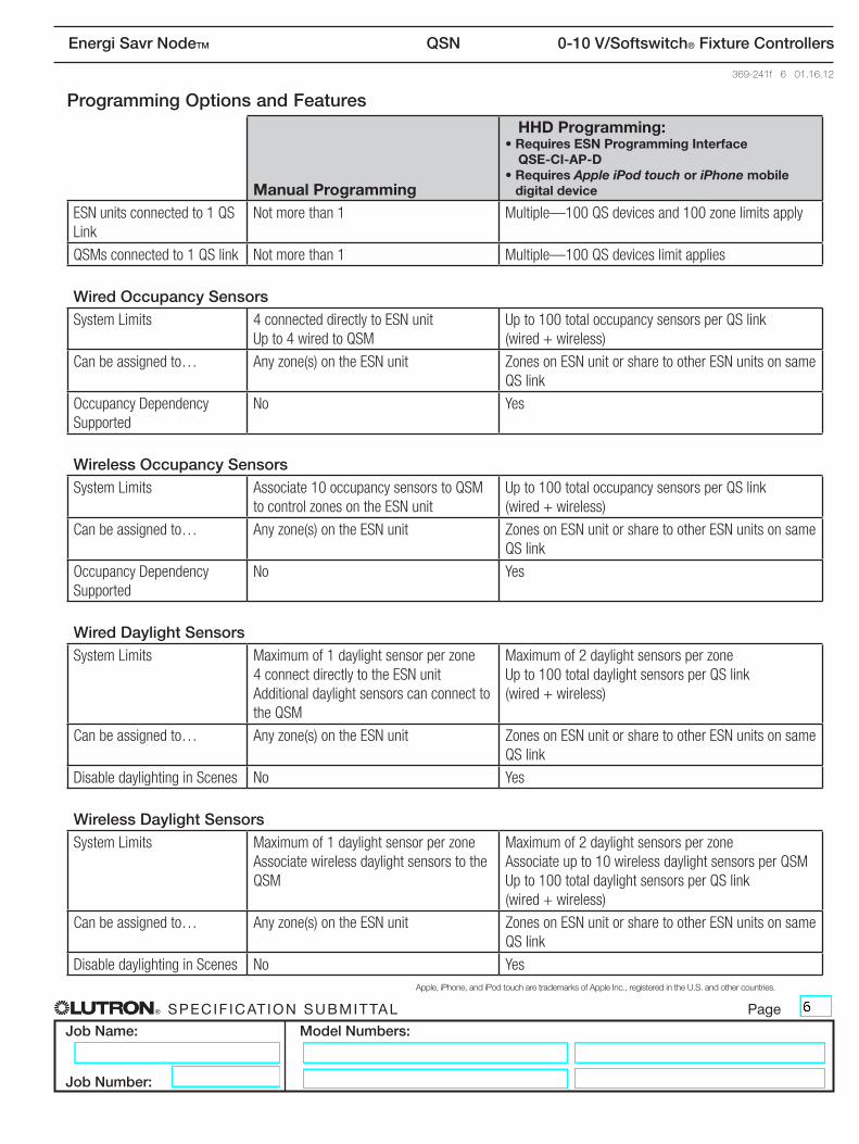
Programming Options and Features
Manual Programming
HHD Programming:• Requires ESN Programming Interface
QSE-CI-AP-D• Requires Apple iPod touch or iPhone mobile
digital device
ESN units connected to 1 QS Link
Not more than 1 Multiple—100 QS devices and 100 zone limits apply
QSMs connected to 1 QS link Not more than 1 Multiple—100 QS devices limit applies
Wired Occupancy SensorsSystem Limits 4 connected directly to ESN unit
Up to 4 wired to QSMUp to 100 total occupancy sensors per QS link (wired + wireless)
Can be assigned to… Any zone(s) on the ESN unit Zones on ESN unit or share to other ESN units on same QS link
Occupancy Dependency Supported
No Yes
Wireless Occupancy SensorsSystem Limits Associate 10 occupancy sensors to QSM
to control zones on the ESN unitUp to 100 total occupancy sensors per QS link (wired + wireless)
Can be assigned to… Any zone(s) on the ESN unit Zones on ESN unit or share to other ESN units on same QS link
Occupancy Dependency Supported
No Yes
Wired Daylight SensorsSystem Limits Maximum of 1 daylight sensor per zone
4 connect directly to the ESN unit Additional daylight sensors can connect to the QSM
Maximum of 2 daylight sensors per zone Up to 100 total daylight sensors per QS link (wired + wireless)
Can be assigned to… Any zone(s) on the ESN unit Zones on ESN unit or share to other ESN units on same QS link
Disable daylighting in Scenes No Yes
Wireless Daylight SensorsSystem Limits Maximum of 1 daylight sensor per zone
Associate wireless daylight sensors to the QSM
Maximum of 2 daylight sensors per zone Associate up to 10 wireless daylight sensors per QSM Up to 100 total daylight sensors per QS link (wired + wireless)
Can be assigned to… Any zone(s) on the ESN unit Zones on ESN unit or share to other ESN units on same QS link
Disable daylighting in Scenes No YesApple,iPhone,andiPodtoucharetrademarksofAppleInc.,registeredintheU.S.andothercountries.
® Specif icat ion Submittal page
Job Name:
Job Number:
Model Numbers:
Energi Savr NodeTM QSN 0-10 V/Softswitch® Fixture Controllers
369-241f 7 01.16.12
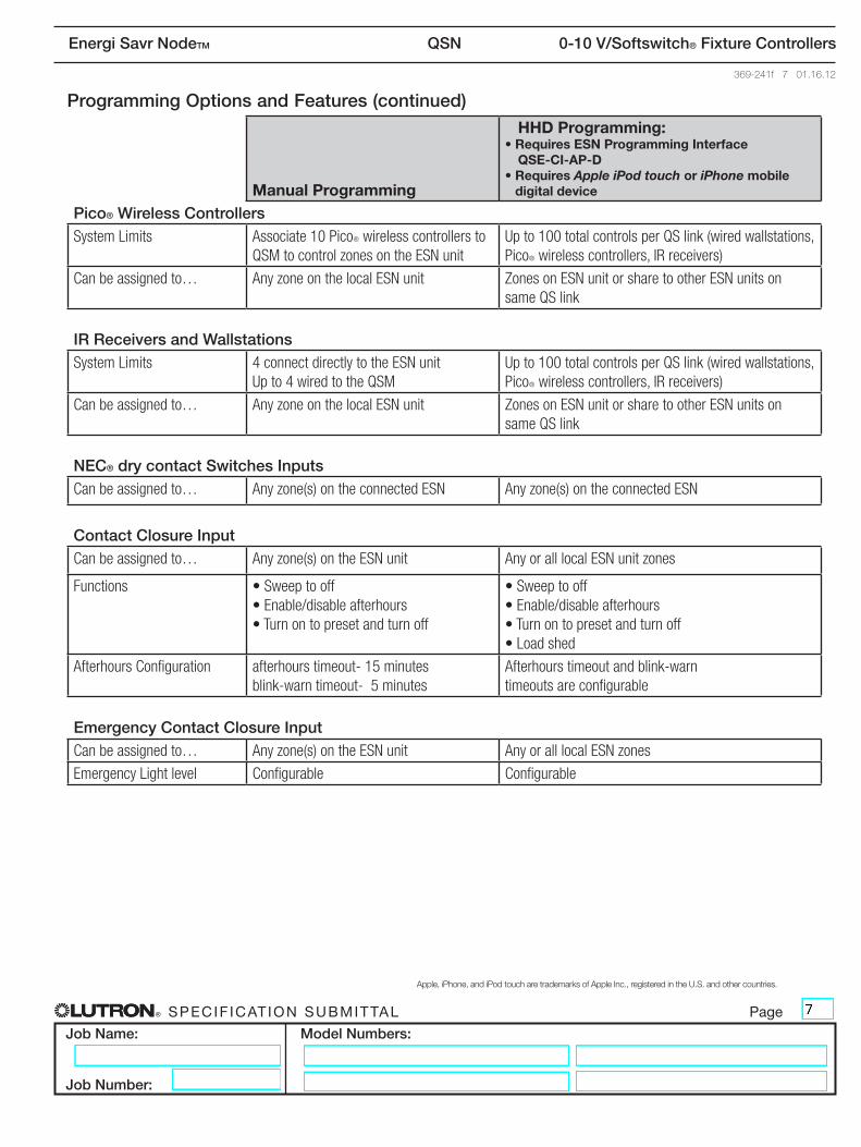
Programming Options and Features (continued)
Manual Programming
HHD Programming:• Requires ESN Programming Interface
QSE-CI-AP-D• Requires Apple iPod touch or iPhone mobile
digital device
Pico® Wireless ControllersSystem Limits Associate 10 PicoR wireless controllers to
QSM to control zones on the ESN unitUp to 100 total controls per QS link (wired wallstations, PicoR wireless controllers, IR receivers)
Can be assigned to… Any zone on the local ESN unit Zones on ESN unit or share to other ESN units on same QS link
IR Receivers and WallstationsSystem Limits 4 connect directly to the ESN unit
Up to 4 wired to the QSMUp to 100 total controls per QS link (wired wallstations, PicoR wireless controllers, IR receivers)
Can be assigned to… Any zone on the local ESN unit Zones on ESN unit or share to other ESN units on same QS link
NEC® dry contact Switches InputsCan be assigned to… Any zone(s) on the connected ESN Any zone(s) on the connected ESN
Contact Closure InputCan be assigned to… Any zone(s) on the ESN unit Any or all local ESN unit zones
Functions • Sweep to off• Enable/disable afterhours• Turn on to preset and turn off
• Sweep to off• Enable/disable afterhours• Turn on to preset and turn off• Load shed
Afterhours Configuration afterhours timeout- 15 minutes blink-warn timeout- 5 minutes
Afterhours timeout and blink-warn timeouts are configurable
Emergency Contact Closure InputCan be assigned to… Any zone(s) on the ESN unit Any or all local ESN zones
Emergency Light level Configurable Configurable
Apple,iPhone,andiPodtoucharetrademarksofAppleInc.,registeredintheU.S.andothercountries.
® Specif icat ion Submittal page
Job Name:
Job Number:
Model Numbers:
Energi Savr NodeTM QSN 0-10 V/Softswitch® Fixture Controllers
369-241f 8 01.16.12
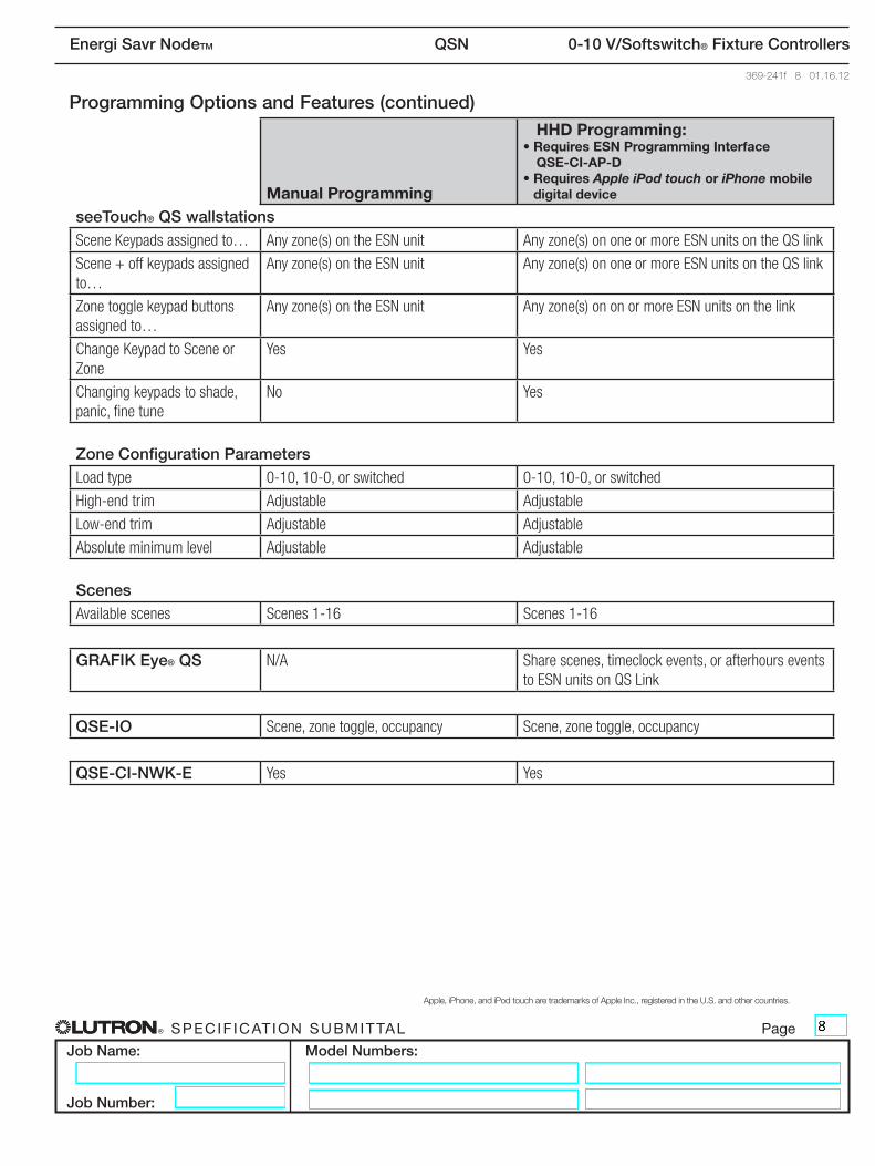
Programming Options and Features (continued)
Manual Programming
HHD Programming:• Requires ESN Programming Interface
QSE-CI-AP-D• Requires Apple iPod touch or iPhone mobile
digital device
seeTouch® QS wallstationsScene Keypads assigned to… Any zone(s) on the ESN unit Any zone(s) on one or more ESN units on the QS link
Scene + off keypads assigned to…
Any zone(s) on the ESN unit Any zone(s) on one or more ESN units on the QS link
Zone toggle keypad buttons assigned to…
Any zone(s) on the ESN unit Any zone(s) on on or more ESN units on the link
Change Keypad to Scene or Zone
Yes Yes
Changing keypads to shade, panic, fine tune
No Yes
Zone Configuration ParametersLoad type 0-10, 10-0, or switched 0-10, 10-0, or switched
High-end trim Adjustable Adjustable
Low-end trim Adjustable Adjustable
Absolute minimum level Adjustable Adjustable
ScenesAvailable scenes Scenes 1-16 Scenes 1-16
GRAFIK Eye® QS N/A Share scenes, timeclock events, or afterhours events to ESN units on QS Link
QSE-IO Scene, zone toggle, occupancy Scene, zone toggle, occupancy
QSE-CI-NWK-E Yes Yes
Apple,iPhone,andiPodtoucharetrademarksofAppleInc.,registeredintheU.S.andothercountries.
® Specif icat ion Submittal page
Job Name:
Job Number:
Model Numbers:
Energi Savr NodeTM QSN 0-10 V/Softswitch® Fixture Controllers
369-241f 9 01.16.12
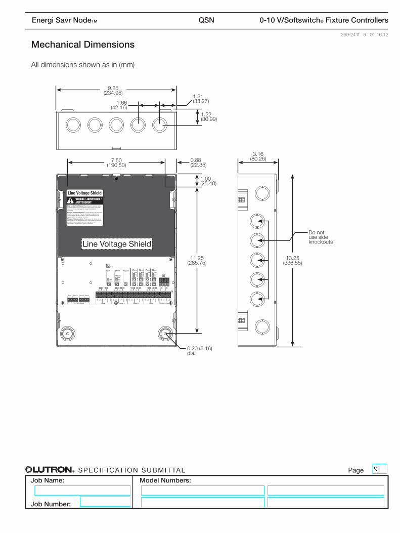
Mechanical Dimensions
All dimensions shown as in (mm)
11.25 (285.75)
0.20 (5.16) dia.
1.00 (25.40)
1.22 (30.99)
1.66 (42.16)
1.31 (33.27)
0.88 (22.35)
9.25 (234.95)
7.50 (190.50)
3.16 (80.26)
13.25 (336.55)
Donotuse side knockoutsline Voltage Shield
® Specif icat ion Submittal page
Job Name:
Job Number:
Model Numbers:
Energi Savr NodeTM QSN 0-10 V/Softswitch® Fixture Controllers
369-241f 10 01.16.12
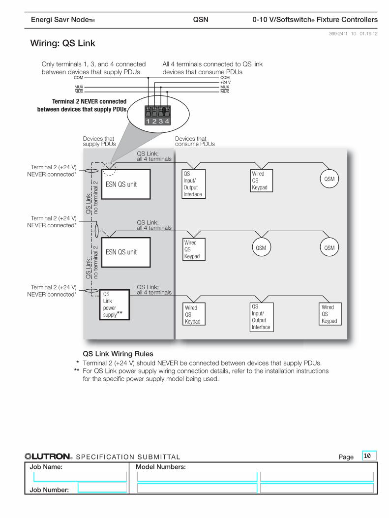
Wiring: QS Link
Onlyterminals1,3,and4connected betweendevicesthatsupplyPDUs
Terminal 2 NEVER connected between devices that supply PDUs
Terminal 2 (+24 V) NEVERconnected*
Devicesthat supplyPDUs
Devicesthat consumePDUs
com+24 VmuXmuX
com
muXmuX
ESN QS unit
ESN QS unit
QS Input/ Output Interface
Wired QS Keypad
QSM
QSMQSMWired QS Keypad
Wired QS Keypad
Wired QS Keypad
QS Input/ Output Interface
QS Link power supply**
QSLink;all 4 terminals
QSLink;
no te
rmin
al 2
QSLink;
no te
rmin
al 2
QSLink;all 4 terminals
QSLink;all 4 terminals
Terminal 2 (+24 V) NEVERconnected*
Terminal 2 (+24 V) NEVERconnected*
All4terminalsconnectedtoQSlink devicesthatconsumePDUs
QS Link Wiring Rules * Terminal2(+24V)shouldNEVERbeconnectedbetweendevicesthatsupplyPDUs.** ForQSLinkpowersupplywiringconnectiondetails,refertotheinstallationinstructions
for the specific power supply model being used.
® Specif icat ion Submittal page
Job Name:
Job Number:
Model Numbers:
Energi Savr NodeTM QSN 0-10 V/Softswitch® Fixture Controllers
369-241f 11 01.16.12
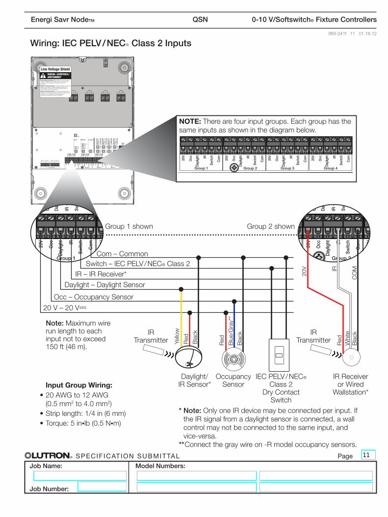
Wiring: IEC PELV / NECR Class 2 Inputs
OccupancySensor
Daylight/ IRSensor*
IR Transmitter
IR Transmitter
Note: Maximum wire run length to each input not to exceed 150 ft (46 m).
IRReceiveror Wired
Wallstation*
IECPELV/NEC® Class 2
DryContactSwitch
Red
Black
Yello
w
Blue/Gray**
Black
Red
20 V – 20 V-
Occ–OccupancySensor
Daylight–DaylightSensor
IR–IRReceiver*Switch – IECPELV/NEC® Class 2
Com – Common
LUTRON
Input Group Wiring:•20AWGto12AWG
(0.5 mm2 to 4.0 mm2)•Striplength:1/4in(6mm)•Torque:5in•lb (0.5 N•m)
NOTE: There are four input groups. Each group has the same inputs as shown in the diagram below.
* Note:OnlyoneIRdevicemaybeconnectedperinput.IftheIRsignalfromadaylightsensorisconnected,awallcontrolmaynotbeconnectedtothesameinput,and vice-versa.
** Connectthegraywireon-Rmodeloccupancysensors.
Group1shown Group2shown
Red
20V
Black
COM
Whi
te
IR
® Specif icat ion Submittal page
Job Name:
Job Number:
Model Numbers:
Energi Savr NodeTM QSN 0-10 V/Softswitch® Fixture Controllers
369-241f 12 01.16.12
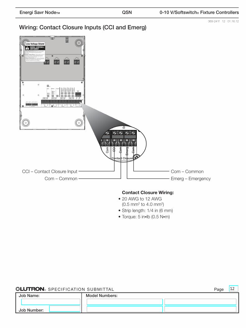
Wiring: Contact Closure Inputs (CCI and Emerg)
Com – Common Emerg – Emergency
CCI–ContactClosureInput Com – Common
Contact Closure Wiring:•20AWGto12AWG
(0.5 mm2 to 4.0 mm2)•Striplength:1/4in(6mm)•Torque:5in•lb (0.5 N•m)
® Specif icat ion Submittal page
Job Name:
Job Number:
Model Numbers:
Energi Savr NodeTM QSN 0-10 V/Softswitch® Fixture Controllers
369-241f 13 01.16.12
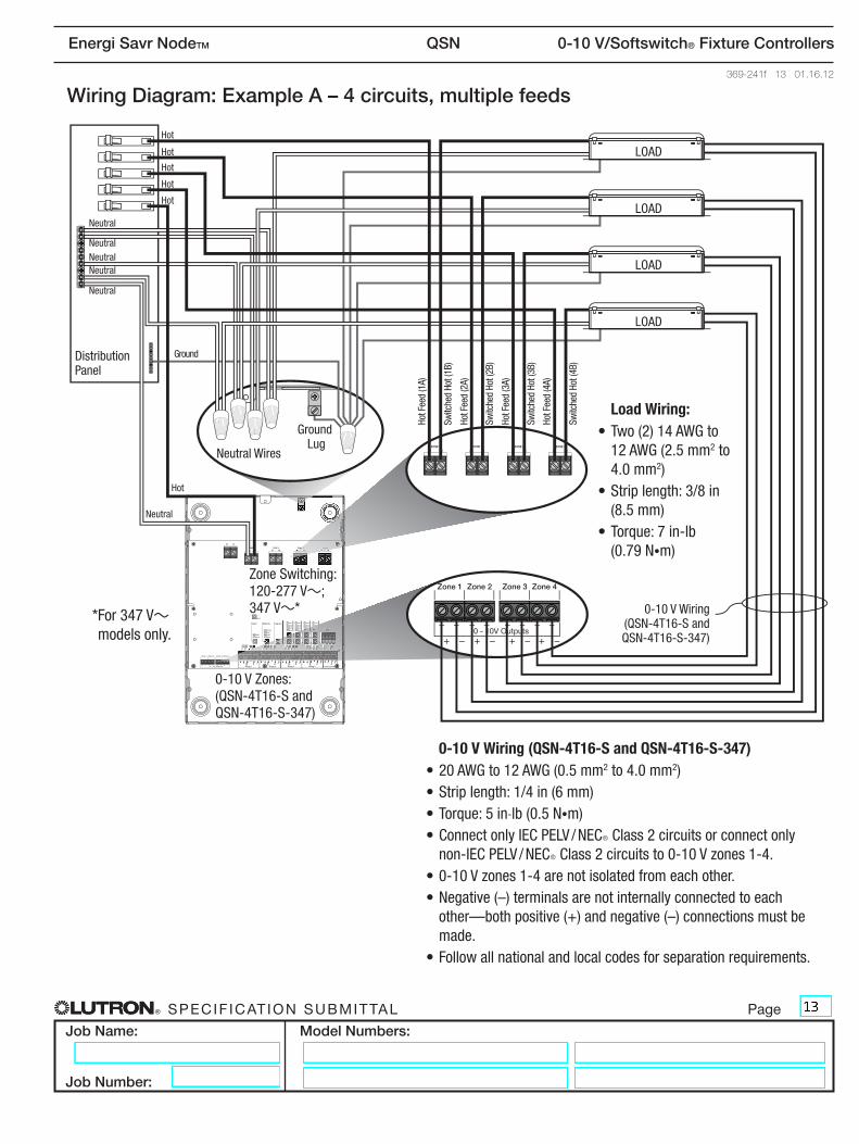
Wiring Diagram: Example A – 4 circuits, multiple feeds
Zone Switching:120-277 V~; 347 V~*
0-10 V Zones:(QSN-4T16-S and QSN-4T16-S-347)
Switc
hed
Hot (
1B)
Hot F
eed
(1A)
Hot F
eed
(2A)
Hot F
eed
(3A)
Hot F
eed
(4A)
Switc
hed
Hot (
2B)
Switc
hed
Hot (
3B)
Switc
hed
Hot (
4B)
Ground Lug
Neutral Wires
Distribution Panel
LOAD
LOAD
LOAD
LOAD
Load Wiring:•Two(2)14AWGto
12 AWG (2.5 mm2 to 4.0 mm2)
•Striplength:3/8in(8.5mm)
•Torque:7in-lb (0.79 N•m)
0-10 V Wiring(QSN-4T16-S and QSN-4T16-S-347)
Hot
Hot
Hot
Hot
Hot
Neutral
Neutral
Neutral
NeutralNeutral
Neutral
Ground
Hot
* For 347 V~ models only.
0-10 V Wiring (QSN-4T16-S and QSN-4T16-S-347)•20AWGto12AWG(0.5mm2 to 4.0 mm2)•Striplength:1/4in(6mm)•Torque:5in-lb (0.5 N•m)•ConnectonlyIECPELV/NECRClass2circuitsorconnectonlynon-IECPELV/NECRClass2circuitsto0-10Vzones1-4.
•0-10Vzones1-4arenotisolatedfromeachother.•Negative(–)terminalsarenotinternallyconnectedtoeachother—bothpositive(+)andnegative(–)connectionsmustbemade.
•Followallnationalandlocalcodesforseparationrequirements.
® Specif icat ion Submittal page
Job Name:
Job Number:
Model Numbers:
Energi Savr NodeTM QSN 0-10 V/Softswitch® Fixture Controllers
369-241f 14 01.16.12
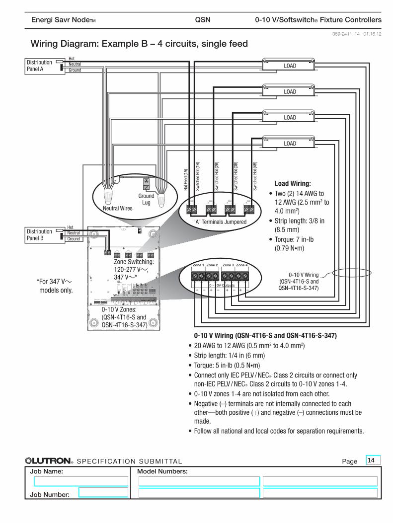
Wiring Diagram: Example B – 4 circuits, single feed
0-10 V Wiring (QSN-4T16-S and QSN-4T16-S-347)•20AWGto12AWG(0.5mm2 to 4.0 mm2)•Striplength:1/4in(6mm)•Torque:5in-lb (0.5 N•m)•ConnectonlyIECPELV/NECRClass2circuitsorconnectonlynon-IECPELV/NECRClass2circuitsto0-10Vzones1-4.
•0-10Vzones1-4arenotisolatedfromeachother.•Negative(–)terminalsarenotinternallyconnectedtoeachother—bothpositive(+)andnegative(–)connectionsmustbemade.
•Followallnationalandlocalcodesforseparationrequirements.
Zone Switching:120-277 V~; 347 V~*
0-10 V Zones:(QSN-4T16-S and QSN-4T16-S-347)
HotNeutralGround
HotNeutralGround
Ground Lug
“A”TerminalsJumpered
Neutral Wires
Distribution Panel A
Distribution Panel B
LOAD
LOAD
LOAD
LOAD
Load Wiring:•Two(2)14AWGto
12 AWG (2.5 mm2 to 4.0 mm2)
•Striplength:3/8in(8.5mm)
•Torque:7in-lb (0.79 N•m)
0-10 V Wiring(QSN-4T16-S and QSN-4T16-S-347)
Switc
hed
Hot (
1B)
Hot F
eed
(1A)
Switc
hed
Hot (
2B)
Switc
hed
Hot (
3B)
Switc
hed
Hot (
4B)
* For 347 V~ models only.
Recommended