Second Half of ENEL 111
Digital Electronics Number Systems and Logic Electronic Gates Combinational Logic Sequential Circuits ADC – DAC circuits Memory and Microprocessors Hardware Description Languages

Hardware Description Language

This Lecture - HDL
What and why HDL Verilog HDL Modelling a simple circuit.
Delays Stimulus
Abstraction Levels Gates Dataflow Proceedural

Hardware Description Language (HDL) Basic idea is a programming language to
describe hardware Initial purpose was to allow abstract design
and simulation Design could be verified then implemented in
hardware Now Synthesis tools allow direct
implementation from HDL code. Large improvement in designer productivity

HDL
HDL allows write-run-debug cycle for hardware development. Similar to programming software Much, much faster than design-implement-debug
Combined with modern Field Programmable Gate Array chips large complex circuits (100000s of gates) can be implemented.
HDLs
There are many different HDLs Verilog HDL ABEL VHDL
VHDL is the most common Large standard developed by US DoD VHDL = VHSIC HDL VHSIC = Very High Speed Integrated Circuit
Verilog HDL
Verilog HDL is second most common Easier to use in many ways = better for teaching C - like syntax
History Developed as proprietry language in 1985 Opened as public domain spec in 1990
Due to losing market share to VHDL Became IEEE standard in 1995
Verilog HDL
Verilog constructs are use defined keywords Examples: and, or, wire, input output
One important construct is the module Modules have inputs and outputs Modules can be built up of Verilog primatives or of
user defined submodules.
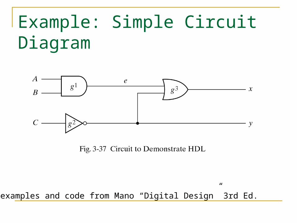
Example: Simple Circuit Diagram
All examples and code from Mano “Digital Design” 3rd Ed.
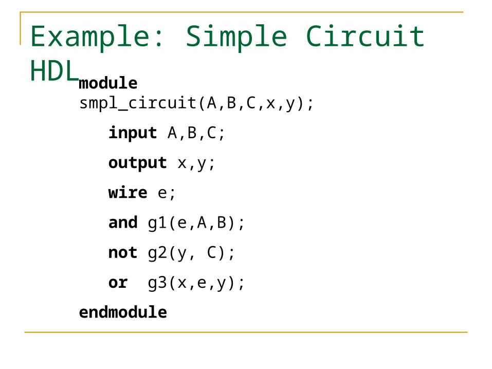
Example: Simple Circuit HDL
module smpl_circuit(A,B,C,x,y);
input A,B,C;
output x,y;
wire e;
and g1(e,A,B);
not g2(y, C);
or g3(x,e,y);
endmodule

Simple Circuit Notes
The module starts with module keyword and finishes with endmodule.
Internal signals are named with wire. Comments follow // input and output are ports. These are
placed at the start of the module definition. Each statement ends with a semicolon,
except endmodule.

Circuit to code
module smpl_circuit(A,B,C,x,y); input A,B,C; output x,y; wire e; and g1(e,A,B); not g2(y, C); or g3(x,e,y);endmodule
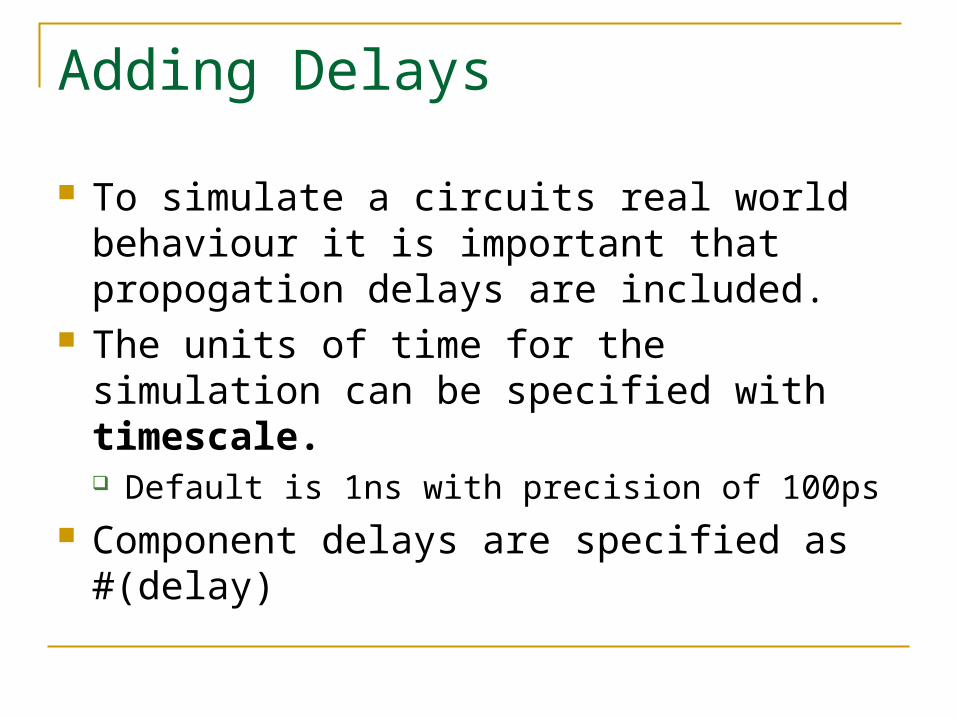
Adding Delays
To simulate a circuits real world behaviour it is important that propogation delays are included.
The units of time for the simulation can be specified with timescale. Default is 1ns with precision of 100ps
Component delays are specified as #(delay)

Simple Circuit with Delaymodule circuit_with_delay (A,B,C,x,y);
input A,B,C;
output x,y;
wire e;
and #(30) g1(e,A,B);
or #(20) g3(x,e,y);
not #(10) g2(y,C);
endmodule
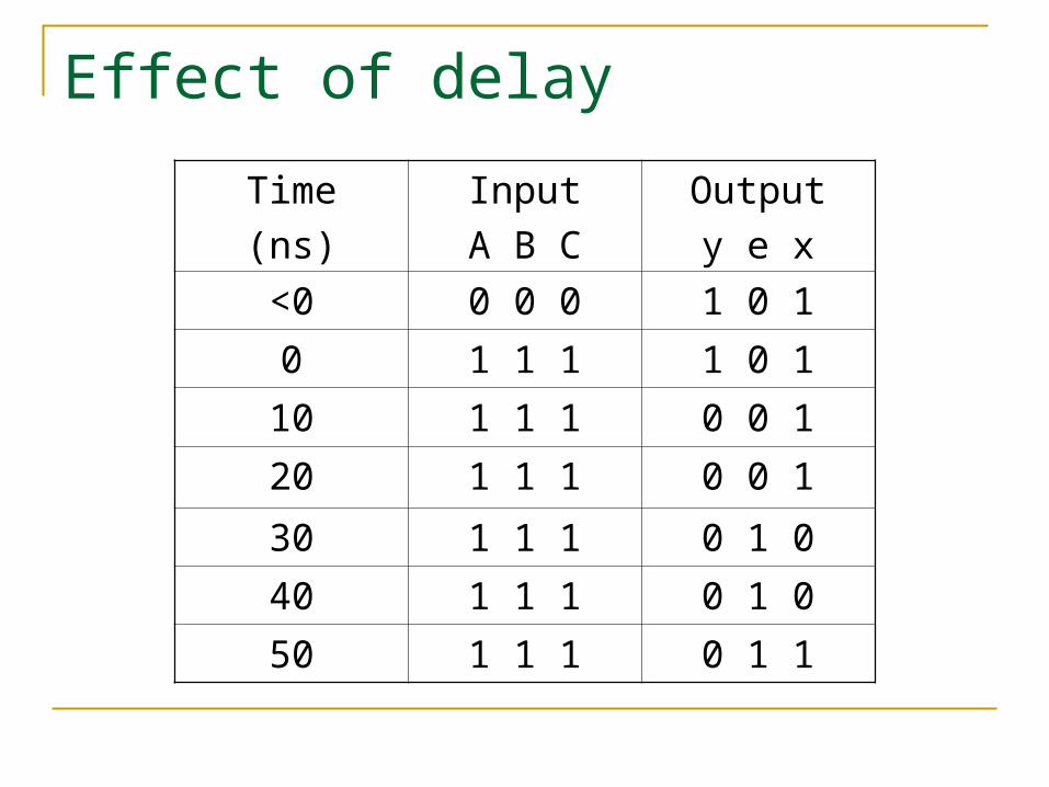
Effect of delay
Time
(ns)
Input
A B C
Output
y e x
<0 0 0 0 1 0 1
0 1 1 1 1 0 1
10 1 1 1 0 0 1
20 1 1 1 0 0 1
30 1 1 1 0 1 0
40 1 1 1 0 1 0
50 1 1 1 0 1 1
Input signals
In order to simulate a circuit the input signals need to be known so as to generate an output signal.
The input signals are often called the circuit stimulus.
An HDL module is written to provide the circuit stimulus. This is known as a testbench.

Testbench
The testbench module includes the module to be tested.
There are no input or output ports for the testbench. The inputs to the test circuit are defined with reg
and the outputs with wire. The input values are specified with the keyword initial
A sequence of values can be specified between begin and end.

Signal Notation
In Verilog signals are generalised to support multi-bit values (e.g. for buses) The notation
A = 1’b0;
means signal A is one bit with value zero. The end of the simulation is specified with $finish.

Stimulus module for simple circuitmodule stimcrct;
reg A,B,C;
wire x,y;
circuit_with_delay cwd(A,B,C,x,y);
initial
begin
A = 1'b0; B = 1'b0; C = 1'b0;
#100
A = 1'b1; B = 1'b1; C = 1'b1;
#100 $finish;
end
endmodule
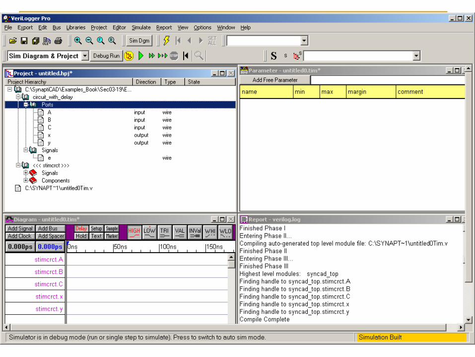


Timing Diagram

Gate Level Modelling
The simple circuit used so far is an example of gate-level modelling.
The module is a text description of the circuit layout.
Verilog has all the standard gates and, nand or, nor xor, xnor not, buf

Primatives
The standard logic gates are Verilog system primatives.
It is possible to specify new user-defined primatives (UDPs).
UDPs are specified by there truth-table. UDPs may only have one output.
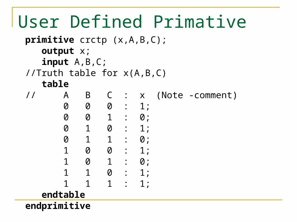
User Defined Primativeprimitive crctp (x,A,B,C); output x; input A,B,C;//Truth table for x(A,B,C) table// A B C : x (Note -comment) 0 0 0 : 1; 0 0 1 : 0; 0 1 0 : 1; 0 1 1 : 0; 1 0 0 : 1; 1 0 1 : 0; 1 1 0 : 1; 1 1 1 : 1; endtable endprimitive

Using a Primative
A Primative by itself is not a module. To use it (e.g. for testing), it needs to be
instantiated in a module. It can be combined with other primatives.
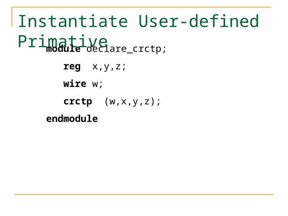
Instantiate User-defined Primativemodule declare_crctp;
reg x,y,z;
wire w;
crctp (w,x,y,z);
endmodule
Dataflow modelling
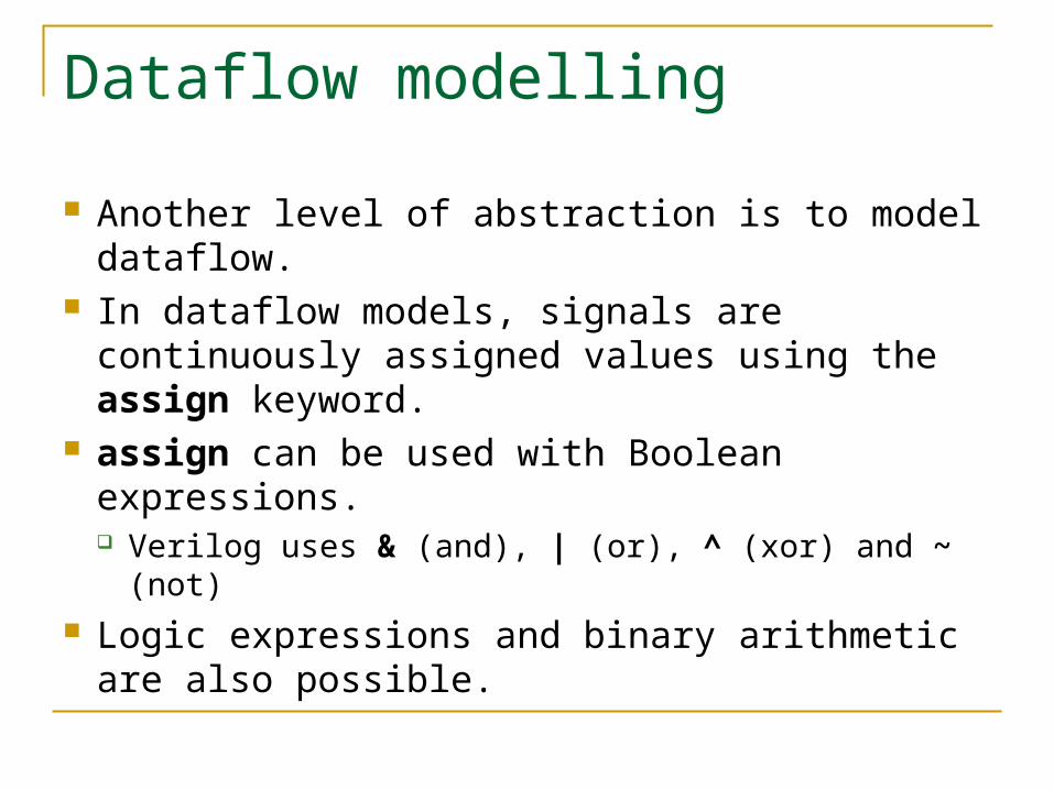
Another level of abstraction is to model dataflow.
In dataflow models, signals are continuously assigned values using the assign keyword.
assign can be used with Boolean expressions. Verilog uses & (and), | (or), ^ (xor) and ~ (not)
Logic expressions and binary arithmetic are also possible.

Simple Circuit Boolean Expression
x = A.B + C
y = C

Boolean Expressions
//Circuit specified with Boolean equations
module circuit_bln (x,y,A,B,C);
input A,B,C;
output x,y;
assign x = A | (B & ~C);
assign y = ~C ;
endmodule
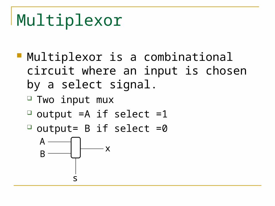
Multiplexor
Multiplexor is a combinational circuit where an input is chosen by a select signal. Two input mux output =A if select =1 output= B if select =0
AB
x
s
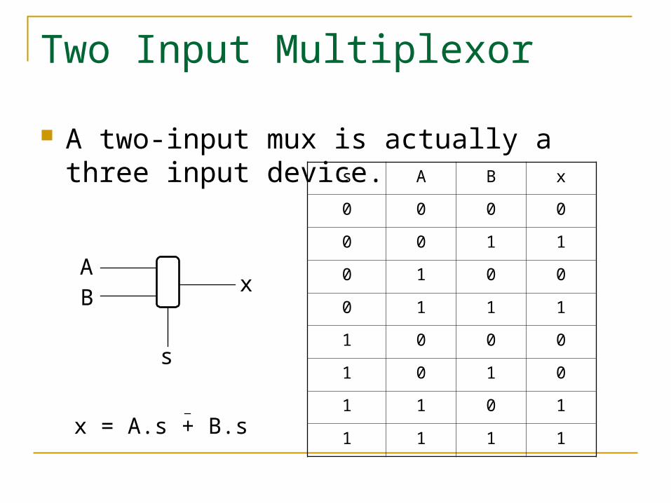
Two Input Multiplexor
A two-input mux is actually a three input device.
AB
x
s
s A B x
0 0 0 0
0 0 1 1
0 1 0 0
0 1 1 1
1 0 0 0
1 0 1 0
1 1 0 1
1 1 1 1x = A.s + B.s
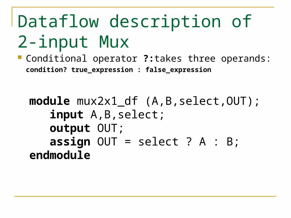
Dataflow description of 2-input Mux Conditional operator ?:takes three operands:
condition? true_expression : false_expression
module mux2x1_df (A,B,select,OUT); input A,B,select; output OUT; assign OUT = select ? A : B;endmodule
Behavioural Modelling
Represents circuits at functional and algorithmic level.
Use proceedural statements similar in concept to proceedural programming languages (e.g. C, Java),
Behavioural modelling is mostly used to represent sequential circuits.

Behavioural Modelling
Behavioural models place proceedural statements in a block after the always keyword.
The always keyword takes a list of variables. The block of statements is executed whenever one of the variables changes.
The target variables are of type reg. This type retains its value until a new value is assigned.

Behavioral description of 2-input mux
module mux2x1_bh(A,B,select,OUT); input A,B,select; output OUT; reg OUT; always @ (select or A or B) if (select == 1) OUT = A; else OUT = B;endmodule
HDL Summary
Hardware Description Languages allow fast design and verification of digital circuits.
Accurate simulation and testing requires delays and inputs to be specified.
There are three different levels of abstraction for modelling circuits.
Recommended