Encore 2G
Operators Guide
Continental Equipment Company, Inc.
Rev. 160301
1 ENCORE 2G OPERATORS GUIDE
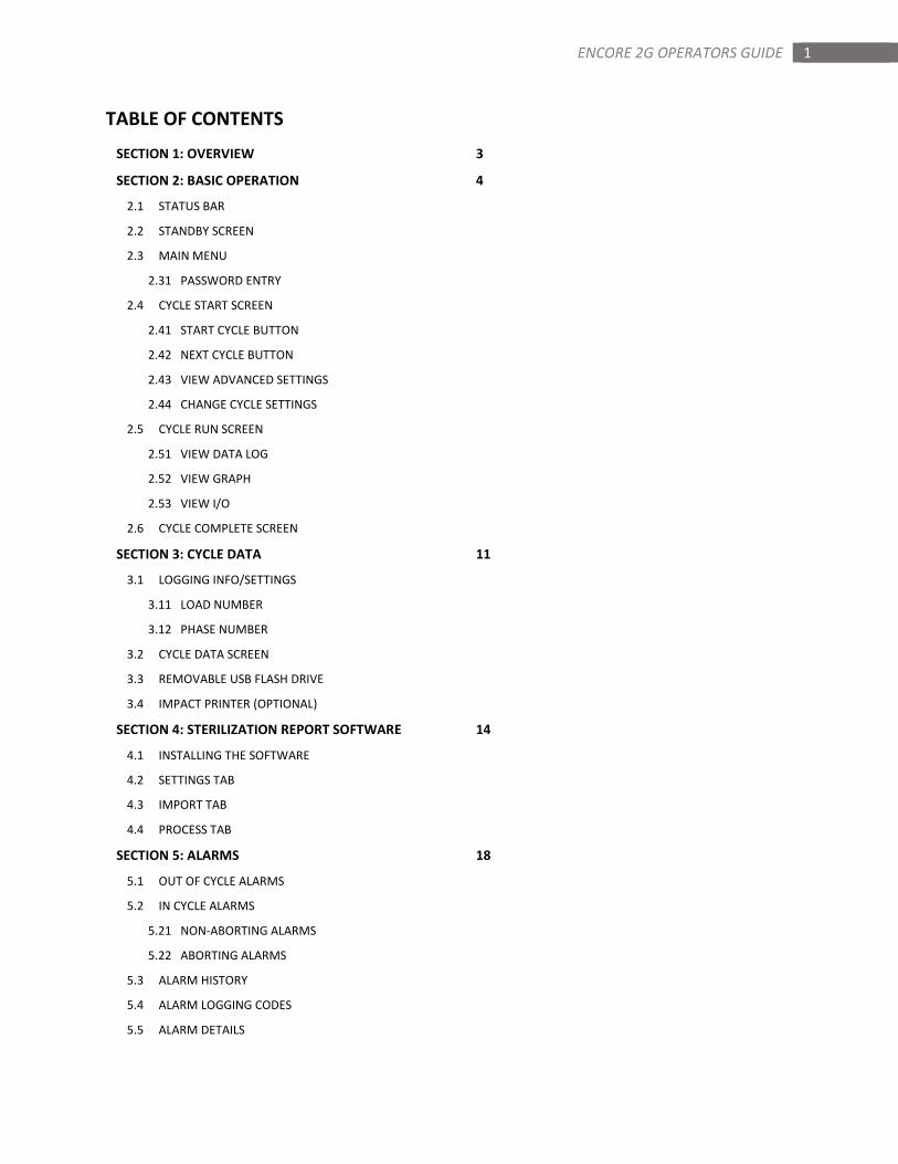
TABLE OF CONTENTS
SECTION 1: OVERVIEW 3
SECTION 2: BASIC OPERATION 4
2.1 STATUS BAR
2.2 STANDBY SCREEN
2.3 MAIN MENU
2.31 PASSWORD ENTRY
2.4 CYCLE START SCREEN
2.41 START CYCLE BUTTON
2.42 NEXT CYCLE BUTTON
2.43 VIEW ADVANCED SETTINGS
2.44 CHANGE CYCLE SETTINGS
2.5 CYCLE RUN SCREEN
2.51 VIEW DATA LOG
2.52 VIEW GRAPH
2.53 VIEW I/O
2.6 CYCLE COMPLETE SCREEN
SECTION 3: CYCLE DATA 11
3.1 LOGGING INFO/SETTINGS
3.11 LOAD NUMBER
3.12 PHASE NUMBER
3.2 CYCLE DATA SCREEN
3.3 REMOVABLE USB FLASH DRIVE
3.4 IMPACT PRINTER (OPTIONAL)
SECTION 4: STERILIZATION REPORT SOFTWARE 14
4.1 INSTALLING THE SOFTWARE
4.2 SETTINGS TAB
4.3 IMPORT TAB
4.4 PROCESS TAB
SECTION 5: ALARMS 18
5.1 OUT OF CYCLE ALARMS
5.2 IN CYCLE ALARMS
5.21 NON-ABORTING ALARMS
5.22 ABORTING ALARMS
5.3 ALARM HISTORY
5.4 ALARM LOGGING CODES
5.5 ALARM DETAILS
2 ENCORE 2G OPERATORS GUIDE
TABLE OF CONTENTS (CONT.)
SECTION 6: CHANGING DATE AND TIME 25
6.1 CHANGING TIME
6.2 CHANGING DATE
SECTION 7: CHANGING CYCLE SETTINGS 26
7.1 CHANGING CYCLE NAME
7.2 CHANGING PRECONDITION SETTINGS
7.3 CHANGING EXPOSURE SETTINGS
7.4 CHANGING POSTCONDITION SETTINGS
7.5 RECOMMENDED CYCLE PARAMETERS
7.51 RECOMMENDED LIQUID CYCLE PARAMETERS
SECTION 8: SPECIALTY CYCLES 34
8.1 LOW TEMP CYCLE
8.2 BOWIE DICK CYCLE
8.3 LEAK TEST CYCLE
SECTION 9: SYSTEM SETUP 35
9.1 SYSTEM OPTIONS
9.2 SYSTEM SETTINGS
9.3 PASSWORD SETTINGS
9.4 ALARM SETTINGS
9.5 BACKUP / RESTORE
9.51 BACKUP
9.52 RESTORE
SECTION 10: SERVICE MODE 42
10.1 INPUT/OUTPUT TEST
10.11 MANUAL OUTPUT OPERATION
10.12 OUTPUTS
10.13 INPUTS
10.14 ANALOG
10.2 CALIBRATION
10.21 LOW CAPTURE
10.22 HIGH CAPTURE
10.23 CALIBRATE
10.24 DEFAULT CALIBRATION
10.25 ENTERING GAIN AND OFFSET DIRECTLY
3 ENCORE 2G OPERATORS GUIDE
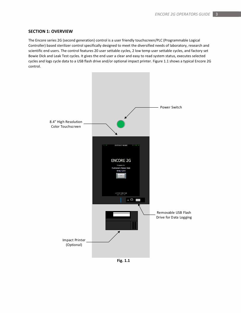
SECTION 1: OVERVIEW
The Encore series 2G (second generation) control is a user friendly touchscreen/PLC (Programmable Logical
Controller) based sterilizer control specifically designed to meet the diversified needs of laboratory, research and
scientific end users. The control features 20 user settable cycles, 2 low temp user settable cycles, and factory set
Bowie Dick and Leak Test cycles. It gives the end user a clear and easy to read system status, executes selected
cycles and logs cycle data to a USB flash drive and/or optional impact printer. Figure 1.1 shows a typical Encore 2G
control.
Power Switch
8.4" High Resolution
Color Touchscreen
Impact Printer
(Optional)
Removable USB Flash
Drive for Data Logging
Fig. 1.1
4 ENCORE 2G OPERATORS GUIDE
SECTION 2: BASIC USER OPERATION
The Encore series 2G control features a high resolution 8.4 inch full color touchscreen. The combination of high
resolution and size enables the control to give the end user the information they need without the need to move
through multiple screens. This section will describe the basic functions, operation, and information for each screen
the end user will use to select and run the basic cycles within the control.
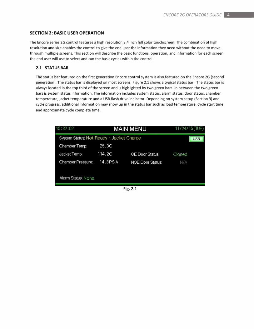
2.1 STATUS BAR
The status bar featured on the first generation Encore control system is also featured on the Encore 2G (second
generation). The status bar is displayed on most screens. Figure 2.1 shows a typical status bar. The status bar is
always located in the top third of the screen and is highlighted by two green bars. In between the two green
bars is system status information. The information includes system status, alarm status, door status, chamber
temperature, jacket temperature and a USB flash drive indicator. Depending on system setup (Section 9) and
cycle progress, additional information may show up in the status bar such as load temperature, cycle start time
and approximate cycle complete time.
Fig. 2.1
5 ENCORE 2G OPERATORS GUIDE
2.2 STANDBY SCREEN
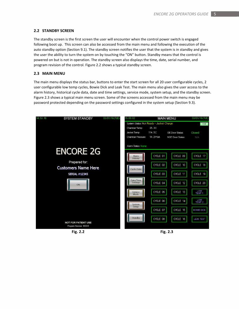
The standby screen is the first screen the user will encounter when the control power switch is engaged
following boot up. This screen can also be accessed from the main menu and following the execution of the
auto standby option (Section 9.1). The standby screen notifies the user that the system is in standby and gives
the user the ability to turn the system on by touching the “ON” button. Standby means that the control is
powered on but is not in operation. The standby screen also displays the time, date, serial number, and
program revision of the control. Figure 2.2 shows a typical standby screen.
2.3 MAIN MENU
The main menu displays the status bar, buttons to enter the start screen for all 20 user configurable cycles, 2
user configurable low temp cycles, Bowie Dick and Leak Test. The main menu also gives the user access to the
alarm history, historical cycle data, date and time settings, service mode, system setup, and the standby screen.
Figure 2.3 shows a typical main menu screen. Some of the screens accessed from the main menu may be
password protected depending on the password settings configured in the system setup (Section 9.3).
Fig. 2.2 Fig. 2.3
6 ENCORE 2G OPERATORS GUIDE
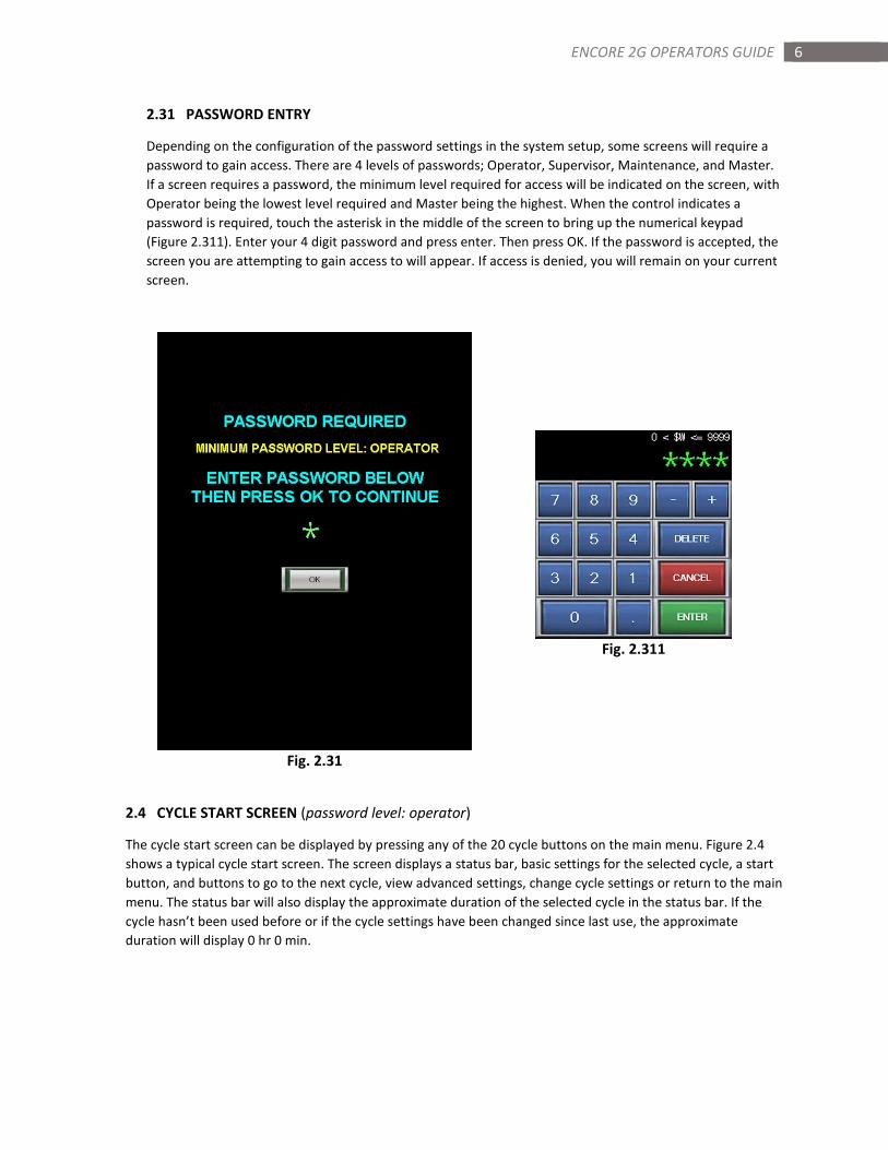
2.31 PASSWORD ENTRY
Depending on the configuration of the password settings in the system setup, some screens will require a
password to gain access. There are 4 levels of passwords; Operator, Supervisor, Maintenance, and Master.
If a screen requires a password, the minimum level required for access will be indicated on the screen, with
Operator being the lowest level required and Master being the highest. When the control indicates a
password is required, touch the asterisk in the middle of the screen to bring up the numerical keypad
(Figure 2.311). Enter your 4 digit password and press enter. Then press OK. If the password is accepted, the
screen you are attempting to gain access to will appear. If access is denied, you will remain on your current
screen.
Fig. 2.311
Fig. 2.31
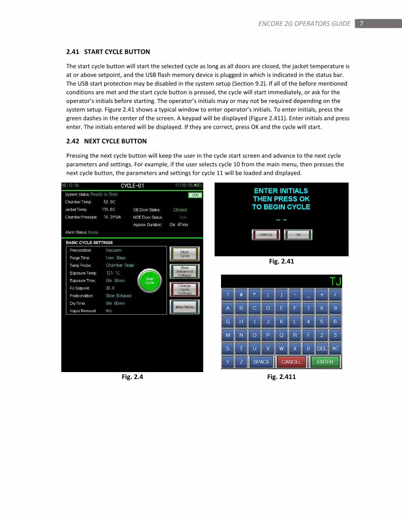
2.4 CYCLE START SCREEN (password level: operator)
The cycle start screen can be displayed by pressing any of the 20 cycle buttons on the main menu. Figure 2.4
shows a typical cycle start screen. The screen displays a status bar, basic settings for the selected cycle, a start
button, and buttons to go to the next cycle, view advanced settings, change cycle settings or return to the main
menu. The status bar will also display the approximate duration of the selected cycle in the status bar. If the
cycle hasn’t been used before or if the cycle settings have been changed since last use, the approximate
duration will display 0 hr 0 min.
7 ENCORE 2G OPERATORS GUIDE
2.41 START CYCLE BUTTON
The start cycle button will start the selected cycle as long as all doors are closed, the jacket temperature is
at or above setpoint, and the USB flash memory device is plugged in which is indicated in the status bar.
The USB start protection may be disabled in the system setup (Section 9.2). If all of the before mentioned
conditions are met and the start cycle button is pressed, the cycle will start immediately, or ask for the
operator’s initials before starting. The operator’s initials may or may not be required depending on the
system setup. Figure 2.41 shows a typical window to enter operator’s initials. To enter initials, press the
green dashes in the center of the screen. A keypad will be displayed (Figure 2.411). Enter initials and press
enter. The initials entered will be displayed. If they are correct, press OK and the cycle will start.
2.42 NEXT CYCLE BUTTON
Pressing the next cycle button will keep the user in the cycle start screen and advance to the next cycle
parameters and settings. For example, if the user selects cycle 10 from the main menu, then presses the
next cycle button, the parameters and settings for cycle 11 will be loaded and displayed.
Fig. 2.41
Fig. 2.4 Fig. 2.411
8 ENCORE 2G OPERATORS GUIDE
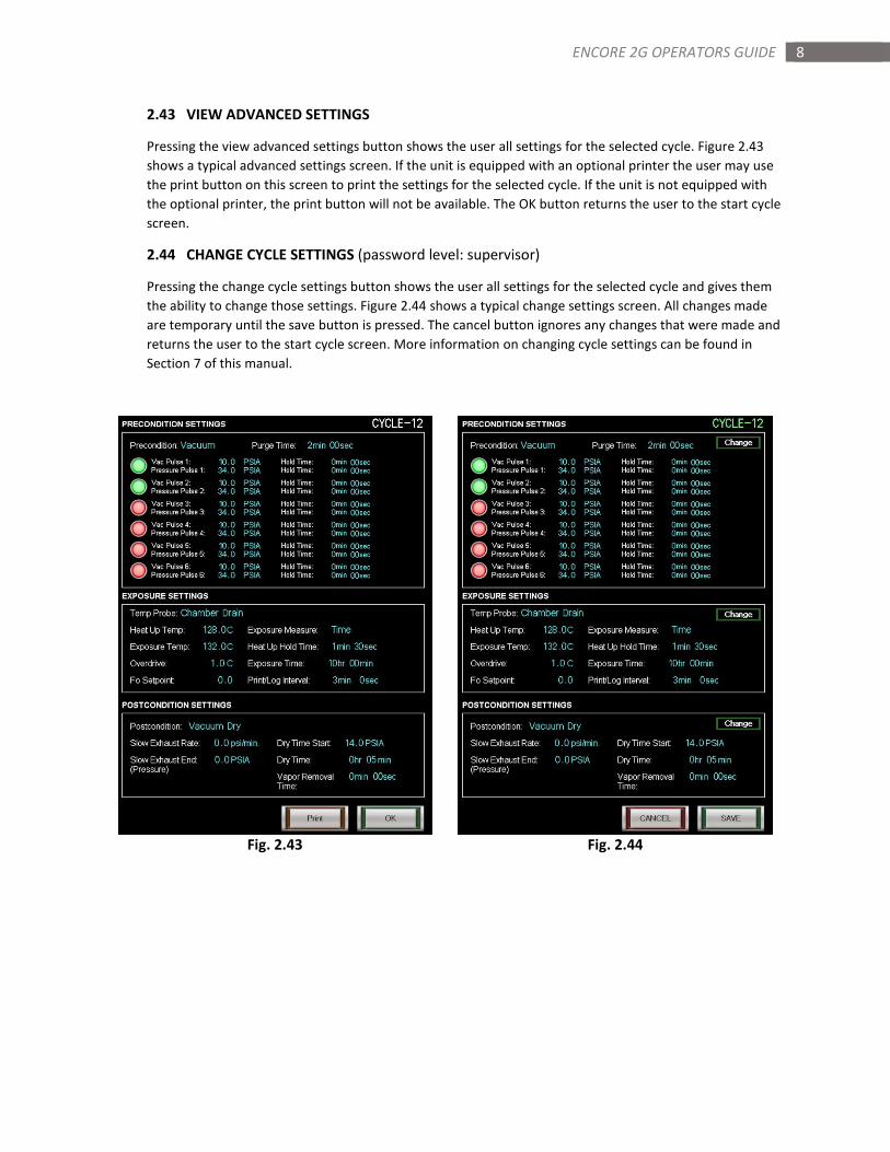
2.43 VIEW ADVANCED SETTINGS
Pressing the view advanced settings button shows the user all settings for the selected cycle. Figure 2.43
shows a typical advanced settings screen. If the unit is equipped with an optional printer the user may use
the print button on this screen to print the settings for the selected cycle. If the unit is not equipped with
the optional printer, the print button will not be available. The OK button returns the user to the start cycle
screen.
2.44 CHANGE CYCLE SETTINGS (password level: supervisor)
Pressing the change cycle settings button shows the user all settings for the selected cycle and gives them
the ability to change those settings. Figure 2.44 shows a typical change settings screen. All changes made
are temporary until the save button is pressed. The cancel button ignores any changes that were made and
returns the user to the start cycle screen. More information on changing cycle settings can be found in
Section 7 of this manual.
Fig. 2.43 Fig. 2.44
9 ENCORE 2G OPERATORS GUIDE
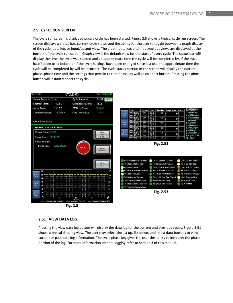
2.5 CYCLE RUN SCREEN
The cycle run screen is displayed once a cycle has been started. Figure 2.5 shows a typical cycle run screen. The
screen displays a status bar, current cycle status and the ability for the user to toggle between a graph display
of the cycle, data log, or input/output view. The graph, data log, and input/output views are displayed at the
bottom of the cycle run screen. Graph view is the default view for the start of every cycle. The status bar will
display the time the cycle was started and an approximate time the cycle will be completed by. If the cycle
hasn’t been used before or if the cycle settings have been changed since last use, the approximate time the
cycle will be completed by will be incorrect. The cycle status portion of the screen will display the current
phase, phase time and the settings that pertain to that phase, as well as an abort button. Pressing the abort
button will instantly abort the cycle.
Fig. 2.51
Fig. 2.53
Fig. 2.5
2.51 VIEW DATA LOG
Pressing the view data log button will display the data log for the current and previous cycles. Figure 2.51
shows a typical data log view. The user may select the list up, list down, and latest data buttons to view
current or past data log information. The cycle phase key gives the user the ability to interpret the phase
portion of the log. For more information on data logging refer to Section 3 of this manual.
10 ENCORE 2G OPERATORS GUIDE
2.52 VIEW GRAPH
Pressing the view graph button will display a graph representation of the last 20 minutes of the current
cycle. The graph displays chamber pressure and chamber temperature. If the control is equipped with a
load probe, the load probe temperature is represented on the graph as well. The user may select the zoom
in, zoom out, and latest data buttons to access different views of the graph. If zoom in or zoom out is
selected, the user must select latest data to return to the view of the graph with real time updating.
2.53 VIEW I/O (INPUTS/OUTPUTS)
Pressing the view I/O button will display the controls inputs (switches) and outputs (valves) that are
actuated during the cycle. Figure 2.53 shows a typical inputs/outputs view. This view would typically be
used by service technicians to verify proper operation or to diagnose a fault. Important note: Some inputs
and outputs listed in this view may not be used on your sterilizer.
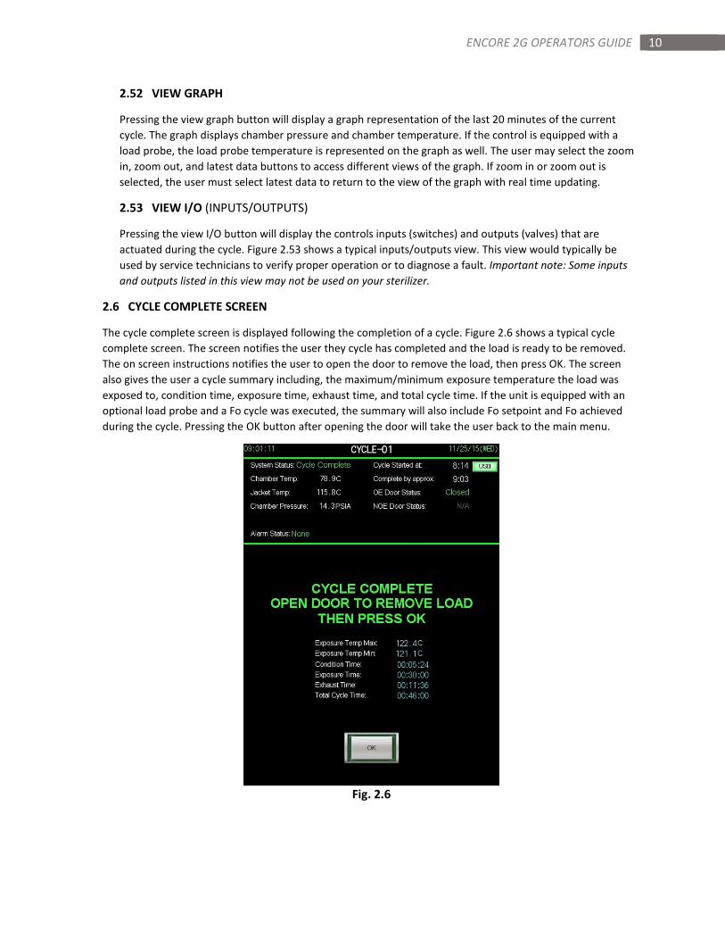
2.6 CYCLE COMPLETE SCREEN
The cycle complete screen is displayed following the completion of a cycle. Figure 2.6 shows a typical cycle
complete screen. The screen notifies the user they cycle has completed and the load is ready to be removed.
The on screen instructions notifies the user to open the door to remove the load, then press OK. The screen
also gives the user a cycle summary including, the maximum/minimum exposure temperature the load was
exposed to, condition time, exposure time, exhaust time, and total cycle time. If the unit is equipped with an
optional load probe and a Fo cycle was executed, the summary will also include Fo setpoint and Fo achieved
during the cycle. Pressing the OK button after opening the door will take the user back to the main menu.
Fig. 2.6
11 ENCORE 2G OPERATORS GUIDE
SECTION 3: CYCLE DATA
The Encore 2G logs all cycle data to a removable USB flash drive. The cycle data that is logged can be viewed on
screen by pressing the cycle data button on the main menu screen, or in real time during cycle by pressing the view
data log button on the cycle run screen. Users may store and back up the data to a PC using the USB flash drive
and the sterilization report software provided. The software can also be used to view and print reports for each
cycle that was logged. The same data and cycle reports can be printed to an optional impact printer. This section
will describe the data logging/printing functions and the screens/settings associated with each.
3.1 LOGGING INFO/SETTINGS
When a cycle is started, the control logs all of the cycle parameters associated with the cycle, assigns a load
number, and begins logging cycle data according to the print/log interval setting (Section 7.3) associated with
the cycle. Each log contains the current time, phase, chamber pressure, chamber temperature, load probe
temperature, and Fo accumulation. At the conclusion of the cycle, the cycle summary is logged including
exposure temperature min/max, condition time, exposure time, exhaust time, and total cycle time.
3.11 LOAD NUMBER
The load number is a unique number for each cycle executed. The number is assigned according to the
exact date and time (military time) the cycle was started. For example, a cycle started on February 25, 2016
at 8:07:25 will be assigned: Load Number 20160225_080725.
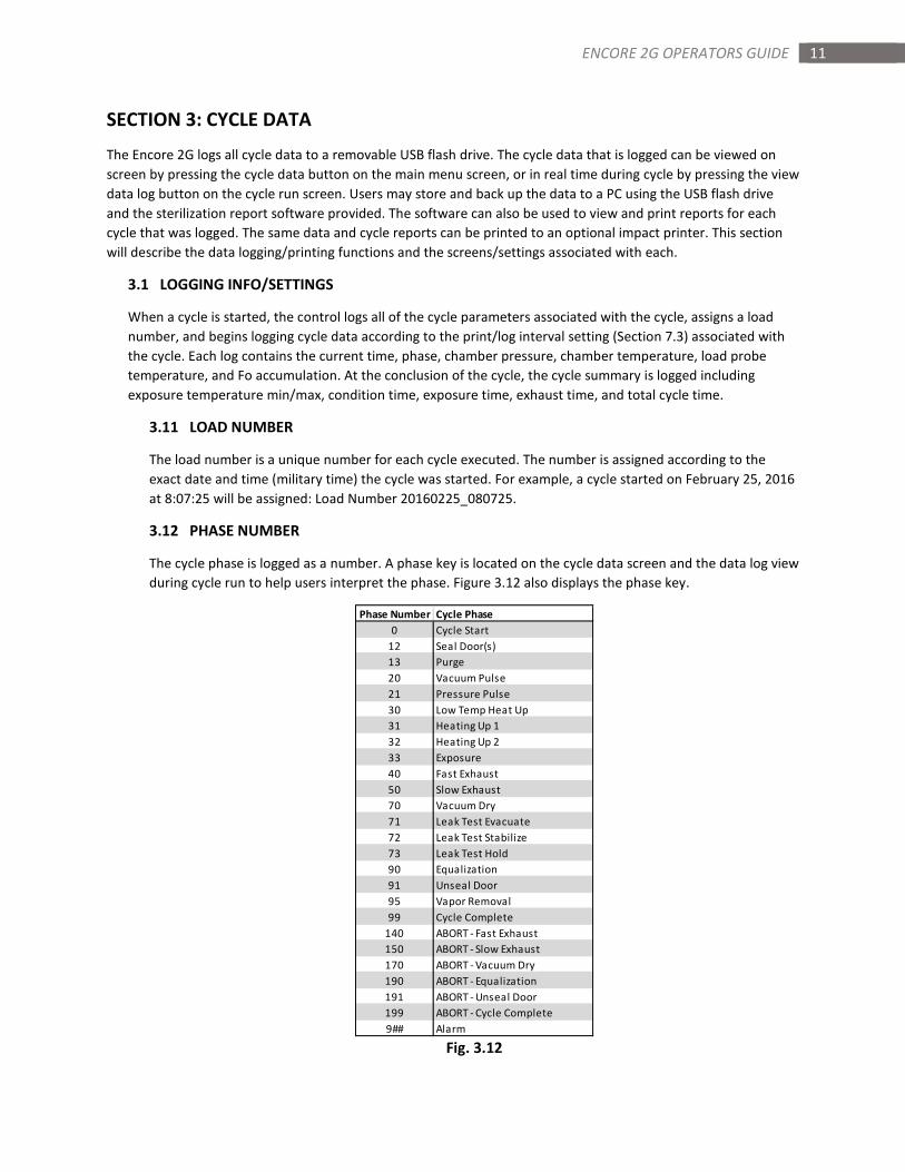
3.12 PHASE NUMBER
The cycle phase is logged as a number. A phase key is located on the cycle data screen and the data log view
during cycle run to help users interpret the phase. Figure 3.12 also displays the phase key.
Fig. 3.12
Phase Number Cycle Phase
0 Cycle Start
12 Seal Door(s)
13 Purge
20 Vacuum Pulse
21 Pressure Pulse
30 Low Temp Heat Up
31 Heating Up 1
32 Heating Up 2
33 Exposure
40 Fast Exhaust
50 Slow Exhaust
70 Vacuum Dry
71 Leak Test Evacuate
72 Leak Test Stabilize
73 Leak Test Hold
90 Equalization
91 Unseal Door
95 Vapor Removal
99 Cycle Complete
140 ABORT - Fast Exhaust
150 ABORT - Slow Exhaust
170 ABORT - Vacuum Dry
190 ABORT - Equalization
191 ABORT - Unseal Door
199 ABORT - Cycle Complete
9## Alarm
12 ENCORE 2G OPERATORS GUIDE
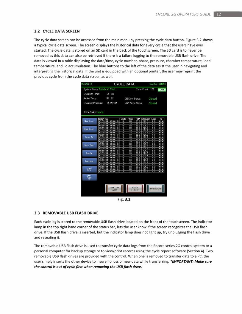
3.2 CYCLE DATA SCREEN
The cycle data screen can be accessed from the main menu by pressing the cycle data button. Figure 3.2 shows
a typical cycle data screen. The screen displays the historical data for every cycle that the users have ever
started. The cycle data is stored on an SD card in the back of the touchscreen. The SD card is to never be
removed as this data can also be retrieved if there is a failure logging to the removable USB flash drive. The
data is viewed in a table displaying the date/time, cycle number, phase, pressure, chamber temperature, load
temperature, and Fo accumulation. The blue buttons to the left of the data assist the user in navigating and
interpreting the historical data. If the unit is equipped with an optional printer, the user may reprint the
previous cycle from the cycle data screen as well.
Fig. 3.2
3.3 REMOVABLE USB FLASH DRIVE
Each cycle log is stored to the removable USB flash drive located on the front of the touchscreen. The indicator
lamp in the top right hand corner of the status bar, lets the user know if the screen recognizes the USB flash
drive. If the USB flash drive is inserted, but the indicator lamp does not light up, try unplugging the flash drive
and reseating it.
The removable USB flash drive is used to transfer cycle data logs from the Encore series 2G control system to a
personal computer for backup storage or to view/print records using the cycle report software (Section 4). Two
removable USB flash drives are provided with the control. When one is removed to transfer data to a PC, the
user simply inserts the other device to insure no loss of new data while transferring. *IMPORTANT: Make sure
the control is out of cycle first when removing the USB flash drive.
13 ENCORE 2G OPERATORS GUIDE
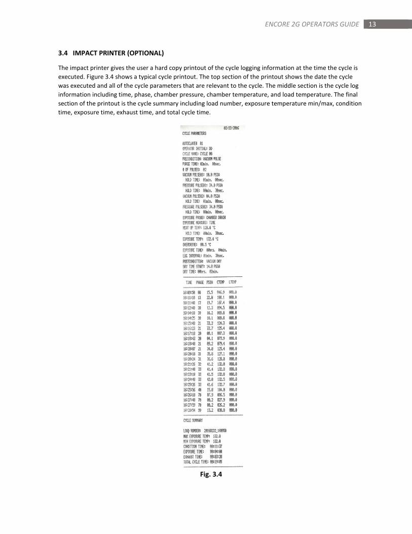
3.4 IMPACT PRINTER (OPTIONAL)
The impact printer gives the user a hard copy printout of the cycle logging information at the time the cycle is
executed. Figure 3.4 shows a typical cycle printout. The top section of the printout shows the date the cycle
was executed and all of the cycle parameters that are relevant to the cycle. The middle section is the cycle log
information including time, phase, chamber pressure, chamber temperature, and load temperature. The final
section of the printout is the cycle summary including load number, exposure temperature min/max, condition
time, exposure time, exhaust time, and total cycle time.
Fig. 3.4
14 ENCORE 2G OPERATORS GUIDE
SECTION 4: STERILIZATION REPORT SOFWARE
The Encore 2G series control is provided with software for your personal computer to manage, store, view and
print cycle reports for each cycle executed. This section describes how to install the software and use it for
transferring and managing cycle data.
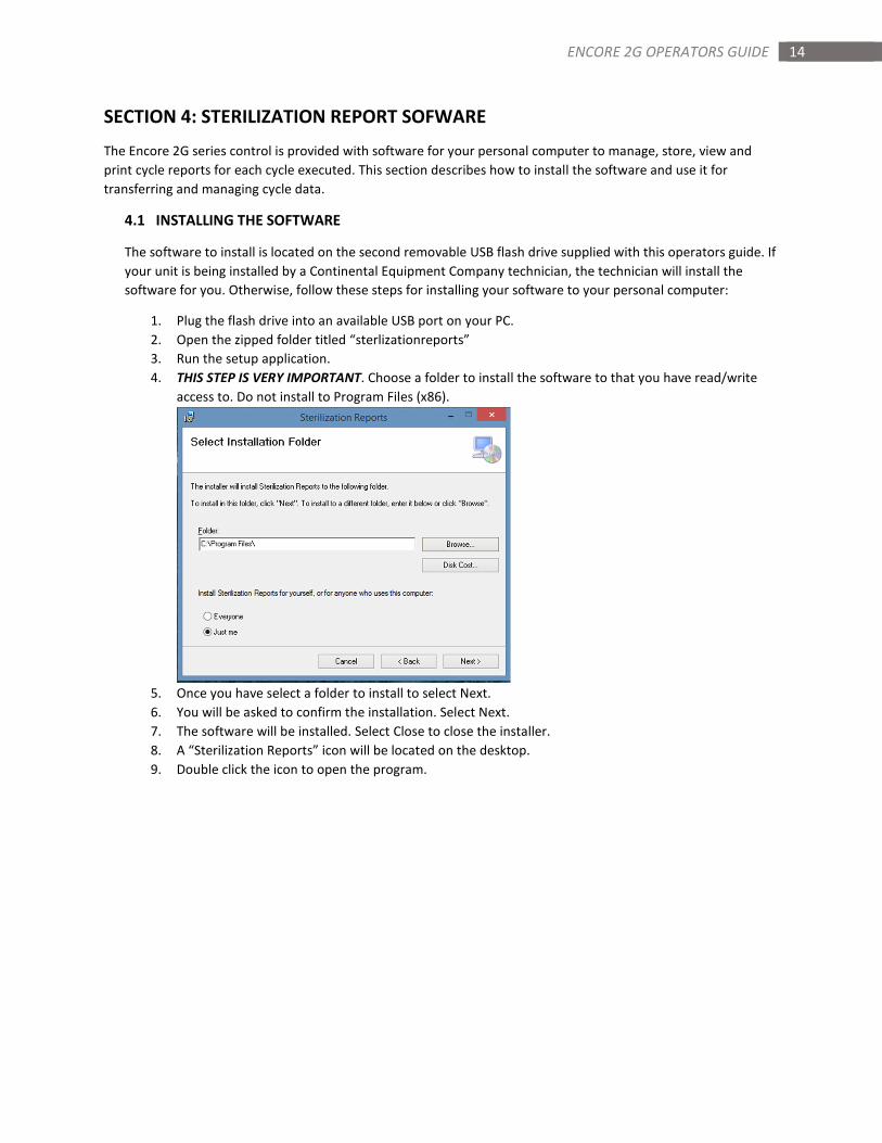
4.1 INSTALLING THE SOFTWARE
The software to install is located on the second removable USB flash drive supplied with this operators guide. If
your unit is being installed by a Continental Equipment Company technician, the technician will install the
software for you. Otherwise, follow these steps for installing your software to your personal computer:
1. Plug the flash drive into an available USB port on your PC.
2. Open the zipped folder titled “sterlizationreports”
3. Run the setup application.
4. THIS STEP IS VERY IMPORTANT. Choose a folder to install the software to that you have read/write
access to. Do not install to Program Files (x86).
5. Once you have select a folder to install to select Next.
6. You will be asked to confirm the installation. Select Next.
7. The software will be installed. Select Close to close the installer.
8. A “Sterilization Reports” icon will be located on the desktop.
9. Double click the icon to open the program.
15 ENCORE 2G OPERATORS GUIDE
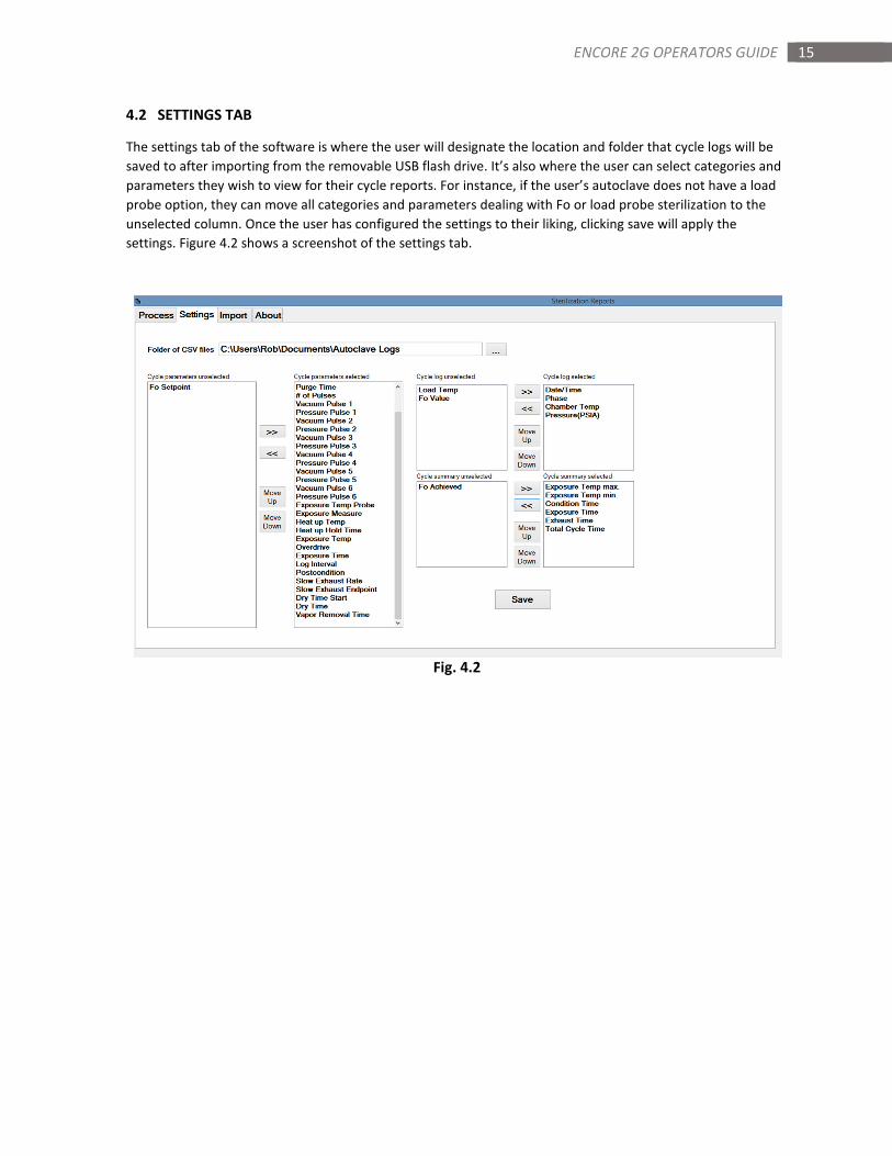
4.2 SETTINGS TAB
The settings tab of the software is where the user will designate the location and folder that cycle logs will be
saved to after importing from the removable USB flash drive. It’s also where the user can select categories and
parameters they wish to view for their cycle reports. For instance, if the user’s autoclave does not have a load
probe option, they can move all categories and parameters dealing with Fo or load probe sterilization to the
unselected column. Once the user has configured the settings to their liking, clicking save will apply the
settings. Figure 4.2 shows a screenshot of the settings tab.
Fig. 4.2
16 ENCORE 2G OPERATORS GUIDE
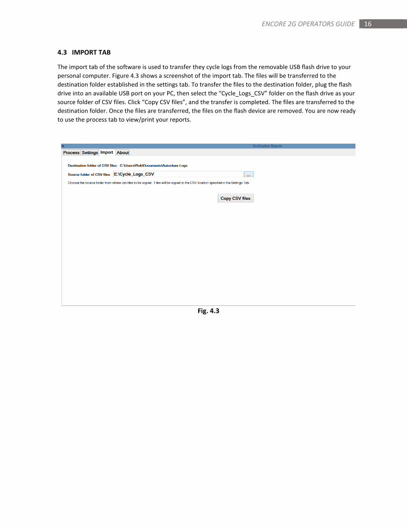
4.3 IMPORT TAB
The import tab of the software is used to transfer they cycle logs from the removable USB flash drive to your
personal computer. Figure 4.3 shows a screenshot of the import tab. The files will be transferred to the
destination folder established in the settings tab. To transfer the files to the destination folder, plug the flash
drive into an available USB port on your PC, then select the “Cycle_Logs_CSV” folder on the flash drive as your
source folder of CSV files. Click “Copy CSV files”, and the transfer is completed. The files are transferred to the
destination folder. Once the files are transferred, the files on the flash device are removed. You are now ready
to use the process tab to view/print your reports.
Fig. 4.3
17 ENCORE 2G OPERATORS GUIDE
4.4 PROCESS TAB
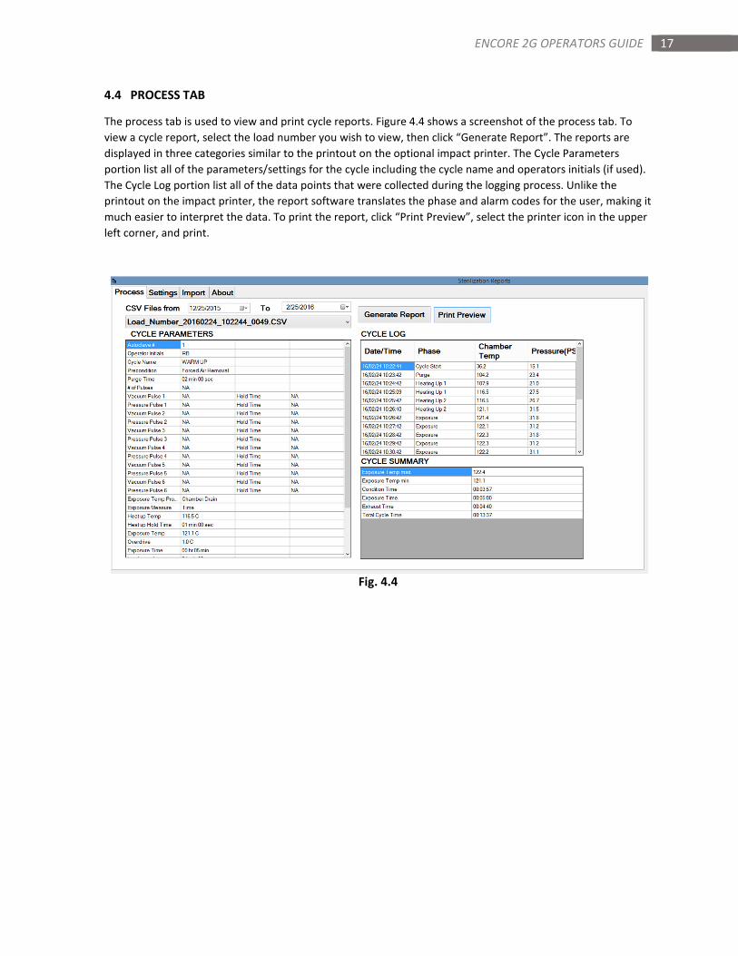
The process tab is used to view and print cycle reports. Figure 4.4 shows a screenshot of the process tab. To
view a cycle report, select the load number you wish to view, then click “Generate Report”. The reports are
displayed in three categories similar to the printout on the optional impact printer. The Cycle Parameters
portion list all of the parameters/settings for the cycle including the cycle name and operators initials (if used).
The Cycle Log portion list all of the data points that were collected during the logging process. Unlike the
printout on the impact printer, the report software translates the phase and alarm codes for the user, making it
much easier to interpret the data. To print the report, click “Print Preview”, select the printer icon in the upper
left corner, and print.
Fig. 4.4
18 ENCORE 2G OPERATORS GUIDE
SECTION 5: ALARMS
The Encore 2G series control monitors your sterilizer for operator safety and sterilization quality. The control will
notify a user of any potential faults during cycle or out of cycle via the alarm status in the status bar. The control
also stores a history of past alarms for reference. This section describes the different types of alarms and how they
are cleared, lists the alarms by alarm code, and describes how to access the alarm history.
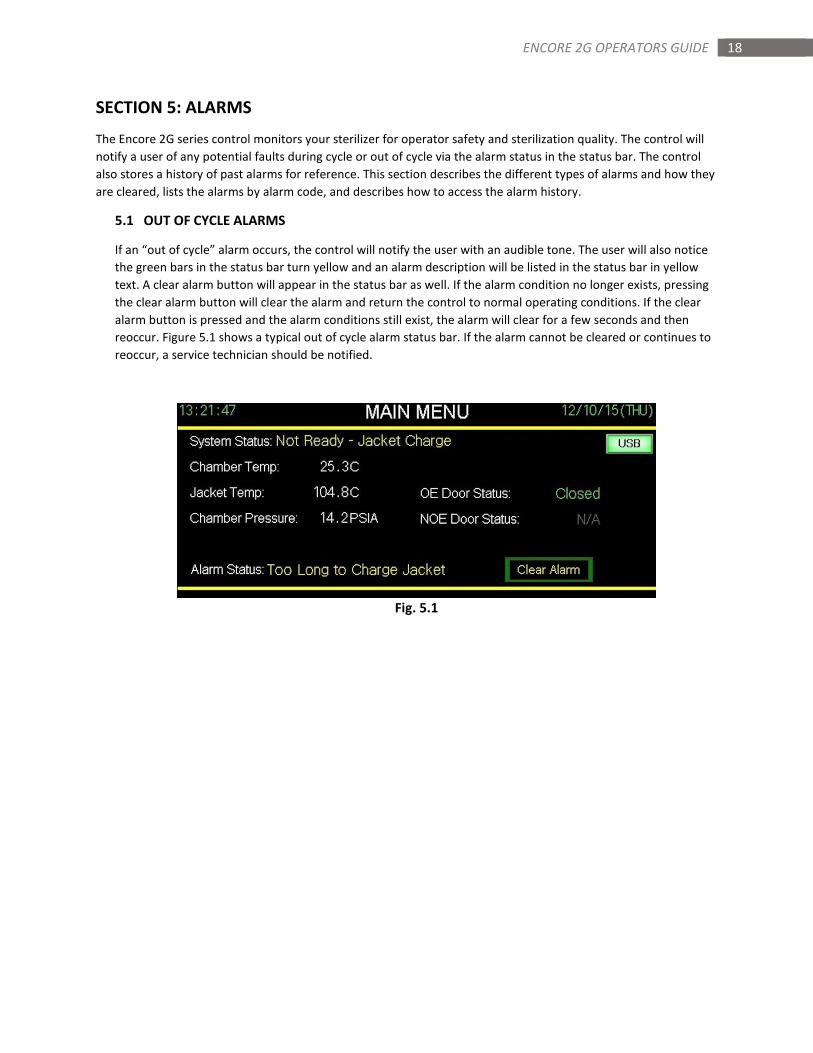
5.1 OUT OF CYCLE ALARMS
If an “out of cycle” alarm occurs, the control will notify the user with an audible tone. The user will also notice
the green bars in the status bar turn yellow and an alarm description will be listed in the status bar in yellow
text. A clear alarm button will appear in the status bar as well. If the alarm condition no longer exists, pressing
the clear alarm button will clear the alarm and return the control to normal operating conditions. If the clear
alarm button is pressed and the alarm conditions still exist, the alarm will clear for a few seconds and then
reoccur. Figure 5.1 shows a typical out of cycle alarm status bar. If the alarm cannot be cleared or continues to
reoccur, a service technician should be notified.
Fig. 5.1
19 ENCORE 2G OPERATORS GUIDE
5.2 IN CYCLE ALARMS
If an “in cycle alarm” occurs, the control will notify the user with an audible tone. The user will also notice the
green bars in the status bar turn yellow and an alarm description will be listed in the status bar in yellow text.
“In cycle alarms” can be aborting or non-aborting. All “in cycle alarms” are logged to the data log of the cycle.
5.21 NON-ABORTING ALARMS
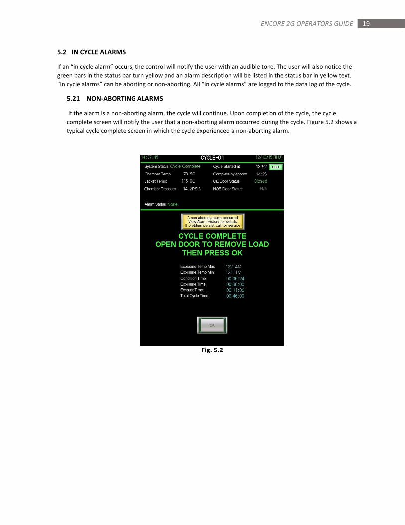
If the alarm is a non-aborting alarm, the cycle will continue. Upon completion of the cycle, the cycle
complete screen will notify the user that a non-aborting alarm occurred during the cycle. Figure 5.2 shows a
typical cycle complete screen in which the cycle experienced a non-aborting alarm.
Fig. 5.2

20 ENCORE 2G OPERATORS GUIDE
5.22 ABORTING ALARMS
If the alarm is an aborting alarm, the cycle will enter an abort sequence. The screen will notify the user that
the cycle has been aborted and to wait for the abort sequence to complete. Figure 5.22 shows a typical
cycle run screen during an abort sequence. Once the abort sequence is complete, the control will notify the
user that the cycle was aborted and instruct the user to open the door then press OK to return to normal
operation. Figure 5.23 shows a typical cycle complete screen following the completion of an abort
sequence.
Fig. 5.22 Fig. 5.23
21 ENCORE 2G OPERATORS GUIDE
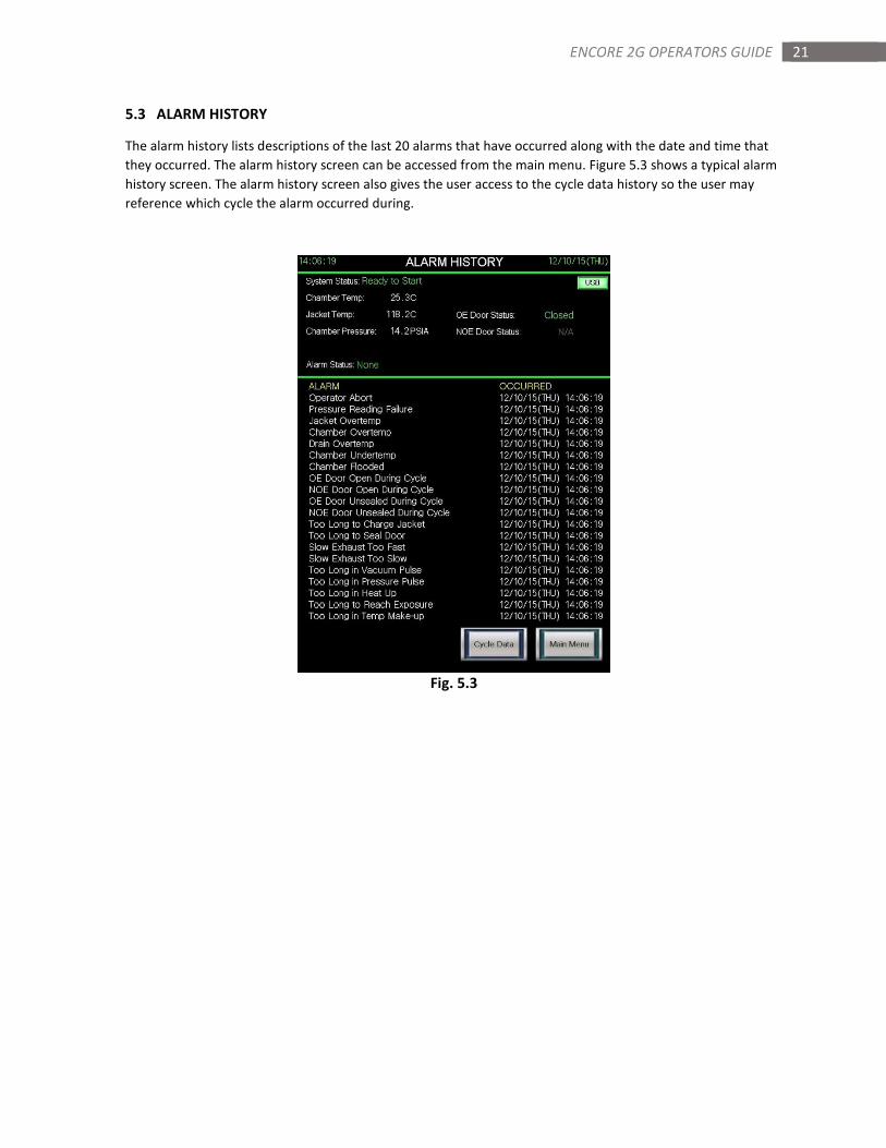
5.3 ALARM HISTORY
The alarm history lists descriptions of the last 20 alarms that have occurred along with the date and time that
they occurred. The alarm history screen can be accessed from the main menu. Figure 5.3 shows a typical alarm
history screen. The alarm history screen also gives the user access to the cycle data history so the user may
reference which cycle the alarm occurred during.
Fig. 5.3

22 ENCORE 2G OPERATORS GUIDE
5.4 ALARM LOGGING CODES
All “in cycle alarms” are logged to the data log of the cycle. The alarm code is found in the phase column of the
data log. The code is a three digit number that always starts with a 9. Figure 5.4 is a listing of all of the alarm
codes, their description, whether the alarm occurs in or out of cycle and the action taken following the alarms
occurrence.
Fig. 5.4
Code Alarm In Cycle or Out Action
901 Operator abort In Cycle Abort
902 Pressure reading failure Out of Cycle Notify
903 Jacket overtemp Both Notify/Abort
904 Chamber overtemp In Cycle Abort
906 Drain overtemp Both Notify/Nonabort
910 Chamber undertemp In Cycle Notify
918 Chaber flooded In Cycle Abort
919 OE door open during cycle In Cycle Abort
920 NOE door open during cycle In Cycle Abort
921 OE door unsealed during cycle In Cycle Abort
922 NOE door unsealed during cycle In Cycle Abort
923 Too long to charge jacket Out of Cycle Notify
924 Too long to seal door In Cycle Abort
925 Slow exhaust too fast In Cycle Notify
926 Slow exhaust too slow In Cycle Notify
927 Too long in vacuum pulse In Cycle Abort
928 Too long in pressure pulse In Cycle Abort
929 Too long in heat up In Cycle Abort
930 Too long to reach exposure In Cycle Abort
931 Too long in temp make up In Cycle Abort
932 Too long in fast exhaust In Cycle Notify
933 Too long in equalization In Cycle Notify
934 Pressure/temperature out of range In Cycle Abort
935 Analog module error Out of Cycle Notify
940 Air utility pressure low Both Notify/Abort
950 Power failure during cycle In Cycle Abort
23 ENCORE 2G OPERATORS GUIDE
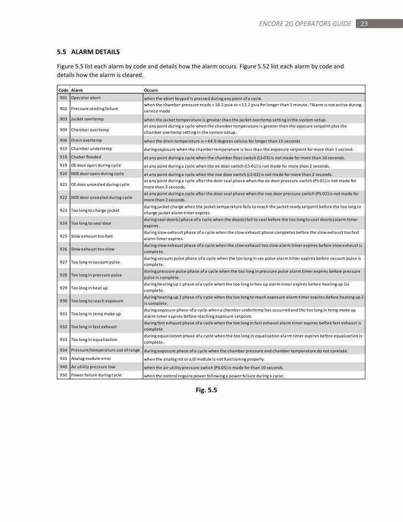
5.5 ALARM DETAILS
Figure 5.5 list each alarm by code and details how the alarm occurs. Figure 5.52 list each alarm by code and
details how the alarm is cleared.
Fig. 5.5
Code Alarm Occurs:
901 Operator abort when the abort keypad is pressed during any point of a cycle.
902 Pressure reading failurewhen the chamber pressure reads > 16.2 psia or < 12.2 psia for longer than 1 minute. *Alarm is not active during
service mode
903 Jacket overtemp when the jacket temperature is greater than the jacket overtemp setting in the system setup.
904 Chamber overtempat any point during a cycle when the chamber temperature is greater than the eposure setpoint plus the
chamber overtemp setting in the system setup.
906 Drain overtemp when the drain temperature is > 64.0 degrees celsius for longer than 15 seconds.
910 Chamber undertemp during exposure when the chamber temperature is less than the exposure setpoint for more than 1 second.
918 Chaber flooded at any point during a cycle when the chamber float switch (LS-03) is not made for more than 10 seconds.
919 OE door open during cycle at any point during a cycle when the oe door switch (LS-01) is not made for more than 2 seconds.
920 NOE door open during cycle at any point during a cycle when the noe door switch (LS-02) is not made for more than 2 seconds.
921 OE door unsealed during cycleat any point during a cycle after the door seal phase when the oe door pressure switch (PS-01) is not made for
more than 2 seconds.
922 NOE door unsealed during cycleat any point during a cycle after the door seal phase when the noe door pressure switch (PS-02) is not made for
more than 2 seconds.
923 Too long to charge jacketduring jacket charge when the jacket temperature fails to reach the jacket ready setpoint before the too long to
charge jacket alarm timer expires.
924 Too long to seal doorduring seal door(s) phase of a cycle when the door(s) fail to seal before the too long to seal door(s) alarm timer
expires.
925 Slow exhaust too fastduring slow exhaust phase of a cycle when the slow exhaust phase completes before the slow exhaust too fast
alarm timer expires.
926 Slow exhaust too slowduring slow exhaust phase of a cycle when the slow exhaust too slow alarm timer expires before slow exhaust is
complete.
927 Too long in vacuum pulseduring vacuum pulse phase of a cycle when the too long in vac pulse alarm timer expires before vacuum pulse is
complete.
928 Too long in pressure pulseduring pressure pulse phase of a cycle when the too long in pressure pulse alarm timer expires before pressure
pulse is complete.
929 Too long in heat upduring heating up 1 phase of a cycle when the too long in hea up alarm timer expires before heating up 1is
complete.
930 Too long to reach exposureduring heating up 2 phase of a cycle when the too long to reach exposure alarm timer expires before heating up 2
is complete.
931 Too long in temp make upduring exposure phase of a cycle when a chamber undertemp has occurred and the too long in temp make up
alarm timer expires before reaching exposure setpoint.
932 Too long in fast exhaustduring fast exhaust phase of a cycle when the too long in fast exhaust alarm timer expires before fast exhaust is
complete.
933 Too long in equalizationduring equalization phase of a cycle when the too long in equalization alarm timer expires before equalization is
complete.
934 Pressure/temperature out of range during exposure phase of a cycle when the chamber pressure and chamber temperature do not corelate.
935 Analog module error when the analog rtd or a/d module is not functioning properly.
940 Air utility pressure low when the air utility pressure swtich (PS-05) is made for than 10 seconds.
950 Power failure during cycle when the control regains power following a power failure during a cycle.
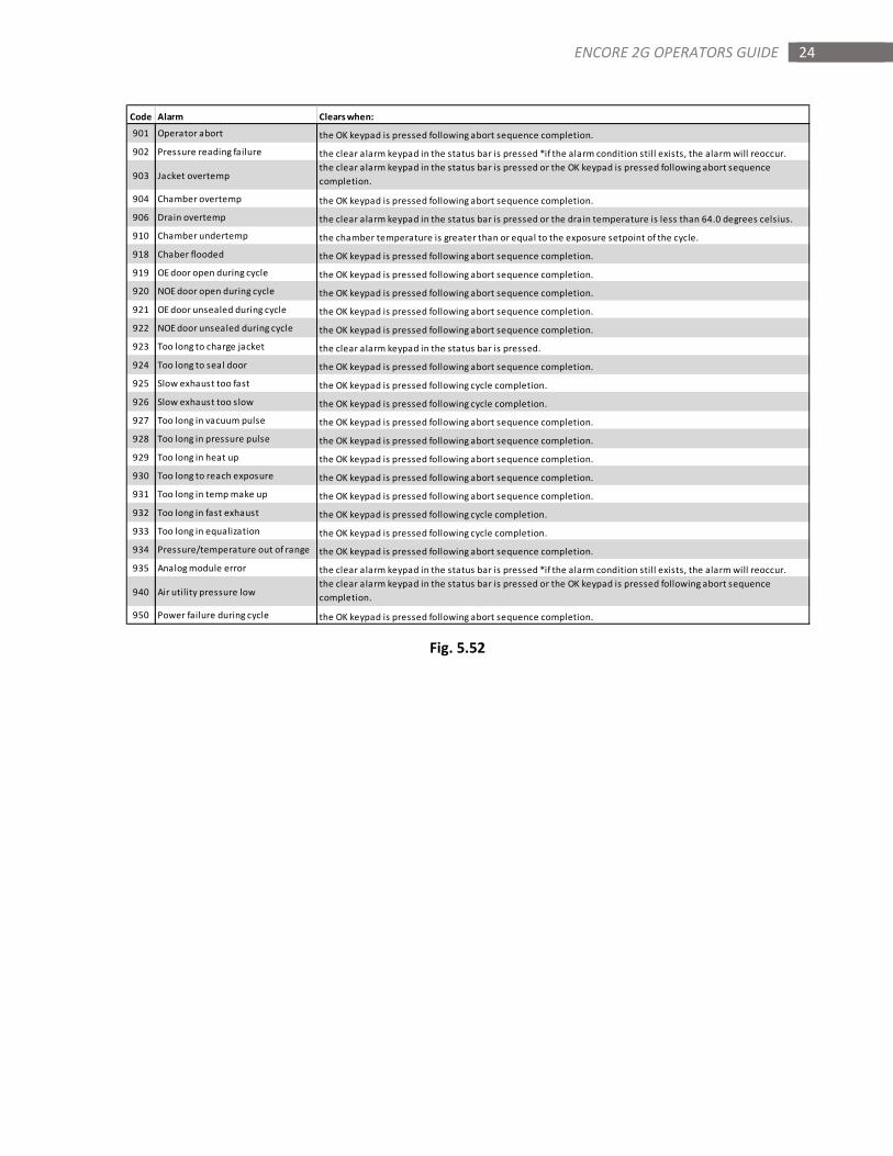
24 ENCORE 2G OPERATORS GUIDE
Fig. 5.52
Code Alarm Clears when:
901 Operator abort the OK keypad is pressed following abort sequence completion.
902 Pressure reading failure the clear alarm keypad in the status bar is pressed *if the alarm condition still exists, the alarm will reoccur.
903 Jacket overtempthe clear alarm keypad in the status bar is pressed or the OK keypad is pressed following abort sequence
completion.
904 Chamber overtemp the OK keypad is pressed following abort sequence completion.
906 Drain overtemp the clear alarm keypad in the status bar is pressed or the drain temperature is less than 64.0 degrees celsius.
910 Chamber undertemp the chamber temperature is greater than or equal to the exposure setpoint of the cycle.
918 Chaber flooded the OK keypad is pressed following abort sequence completion.
919 OE door open during cycle the OK keypad is pressed following abort sequence completion.
920 NOE door open during cycle the OK keypad is pressed following abort sequence completion.
921 OE door unsealed during cycle the OK keypad is pressed following abort sequence completion.
922 NOE door unsealed during cycle the OK keypad is pressed following abort sequence completion.
923 Too long to charge jacket the clear alarm keypad in the status bar is pressed.
924 Too long to seal door the OK keypad is pressed following abort sequence completion.
925 Slow exhaust too fast the OK keypad is pressed following cycle completion.
926 Slow exhaust too slow the OK keypad is pressed following cycle completion.
927 Too long in vacuum pulse the OK keypad is pressed following abort sequence completion.
928 Too long in pressure pulse the OK keypad is pressed following abort sequence completion.
929 Too long in heat up the OK keypad is pressed following abort sequence completion.
930 Too long to reach exposure the OK keypad is pressed following abort sequence completion.
931 Too long in temp make up the OK keypad is pressed following abort sequence completion.
932 Too long in fast exhaust the OK keypad is pressed following cycle completion.
933 Too long in equalization the OK keypad is pressed following cycle completion.
934 Pressure/temperature out of range the OK keypad is pressed following abort sequence completion.
935 Analog module error the clear alarm keypad in the status bar is pressed *if the alarm condition still exists, the alarm will reoccur.
940 Air utility pressure lowthe clear alarm keypad in the status bar is pressed or the OK keypad is pressed following abort sequence
completion.
950 Power failure during cycle the OK keypad is pressed following abort sequence completion.
25 ENCORE 2G OPERATORS GUIDE
SECTON 6: CHANGING DATE AND TIME
The Encore 2G series control uses the clock in the PLC to display and log date and time. The PLC broadcasts the
time and date to the touchscreen(s). Every minute, the touchscreen(s) check the PLC to make sure the date and
time displayed on the screen(s) are accurate and updates accordingly. This section describes how to change the
date and time settings in the PLC.
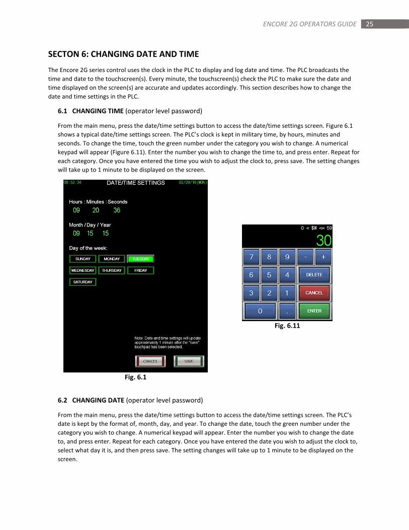
6.1 CHANGING TIME (operator level password)
From the main menu, press the date/time settings button to access the date/time settings screen. Figure 6.1
shows a typical date/time settings screen. The PLC’s clock is kept in military time, by hours, minutes and
seconds. To change the time, touch the green number under the category you wish to change. A numerical
keypad will appear (Figure 6.11). Enter the number you wish to change the time to, and press enter. Repeat for
each category. Once you have entered the time you wish to adjust the clock to, press save. The setting changes
will take up to 1 minute to be displayed on the screen.
Fig. 6.11
Fig. 6.1
6.2 CHANGING DATE (operator level password)
From the main menu, press the date/time settings button to access the date/time settings screen. The PLC’s
date is kept by the format of, month, day, and year. To change the date, touch the green number under the
category you wish to change. A numerical keypad will appear. Enter the number you wish to change the date
to, and press enter. Repeat for each category. Once you have entered the date you wish to adjust the clock to,
select what day it is, and then press save. The setting changes will take up to 1 minute to be displayed on the
screen.
26 ENCORE 2G OPERATORS GUIDE
SECTION 7: CHANGING CYCLE SETTINGS
The Encore 2G’s cycle settings are designed to meet the versatile needs of laboratory, research and scientific end
users. This section will describe how to change and save cycle settings, as well as give descriptions for many of the
settings. Refer to section 2.4 of this manual for information on how to access the change cycle settings screen.
Cycle settings are password protected at supervisor level if made active in the system setup (Section 9.3).
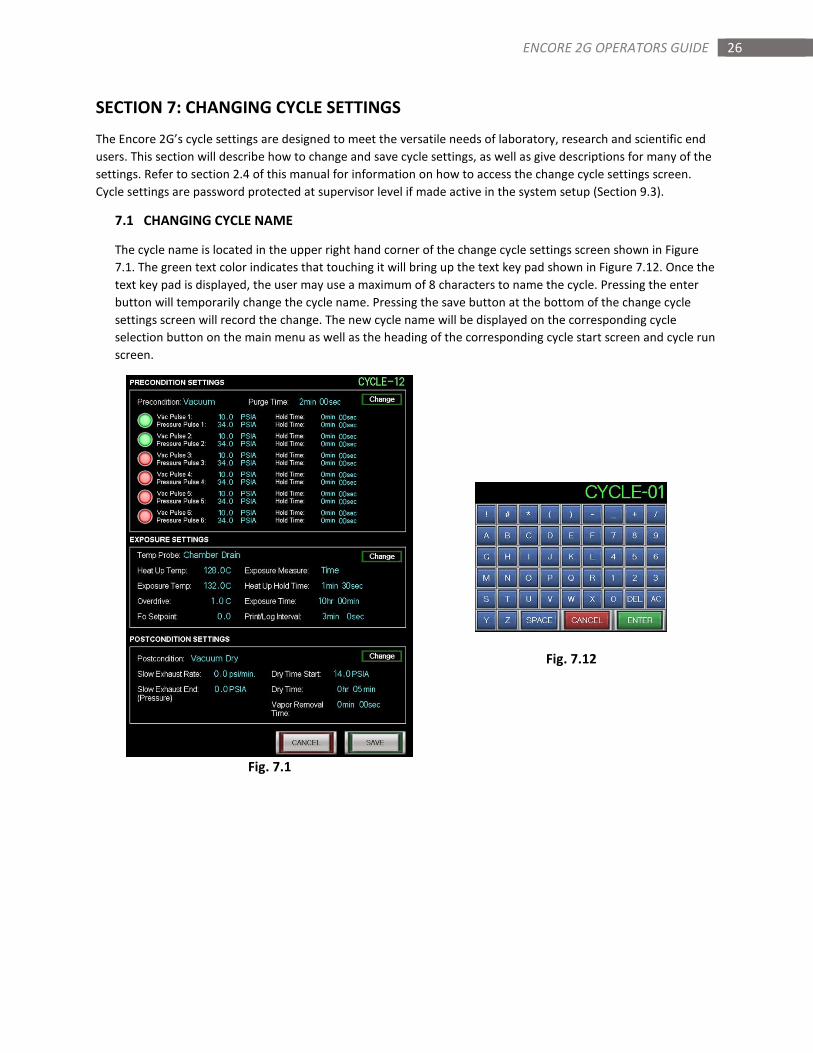
7.1 CHANGING CYCLE NAME
The cycle name is located in the upper right hand corner of the change cycle settings screen shown in Figure
7.1. The green text color indicates that touching it will bring up the text key pad shown in Figure 7.12. Once the
text key pad is displayed, the user may use a maximum of 8 characters to name the cycle. Pressing the enter
button will temporarily change the cycle name. Pressing the save button at the bottom of the change cycle
settings screen will record the change. The new cycle name will be displayed on the corresponding cycle
selection button on the main menu as well as the heading of the corresponding cycle start screen and cycle run
screen.
Fig. 7.12
Fig. 7.1
27 ENCORE 2G OPERATORS GUIDE
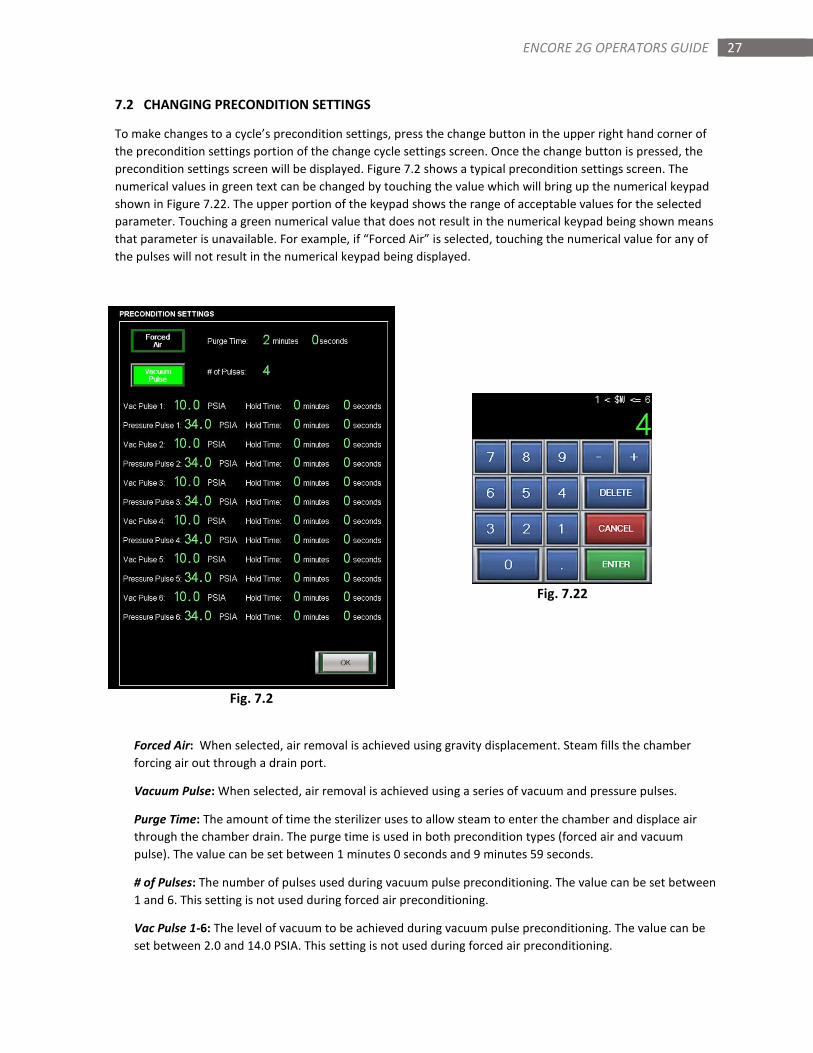
7.2 CHANGING PRECONDITION SETTINGS
To make changes to a cycle’s precondition settings, press the change button in the upper right hand corner of
the precondition settings portion of the change cycle settings screen. Once the change button is pressed, the
precondition settings screen will be displayed. Figure 7.2 shows a typical precondition settings screen. The
numerical values in green text can be changed by touching the value which will bring up the numerical keypad
shown in Figure 7.22. The upper portion of the keypad shows the range of acceptable values for the selected
parameter. Touching a green numerical value that does not result in the numerical keypad being shown means
that parameter is unavailable. For example, if “Forced Air” is selected, touching the numerical value for any of
the pulses will not result in the numerical keypad being displayed.
Fig. 7.22
Fig. 7.2
Forced Air: When selected, air removal is achieved using gravity displacement. Steam fills the chamber
forcing air out through a drain port.
Vacuum Pulse: When selected, air removal is achieved using a series of vacuum and pressure pulses.
Purge Time: The amount of time the sterilizer uses to allow steam to enter the chamber and displace air
through the chamber drain. The purge time is used in both precondition types (forced air and vacuum
pulse). The value can be set between 1 minutes 0 seconds and 9 minutes 59 seconds.
# of Pulses: The number of pulses used during vacuum pulse preconditioning. The value can be set between
1 and 6. This setting is not used during forced air preconditioning.
Vac Pulse 1-6: The level of vacuum to be achieved during vacuum pulse preconditioning. The value can be
set between 2.0 and 14.0 PSIA. This setting is not used during forced air preconditioning.

28 ENCORE 2G OPERATORS GUIDE
Pressure Pulse 1-6: The level of pressure to be achieved during vacuum pulse preconditioning. The value
can be set between 15.0 and 40.0 PSIA. This setting is not used during forced air preconditioning.
Hold Time: The amount of time the vacuum or pressure level will be held during vacuum pulse
preconditioning. The value can be set between 0 minutes 0 seconds and 10 minutes 59 seconds. This setting
is not used during forced air preconditioning.
29 ENCORE 2G OPERATORS GUIDE
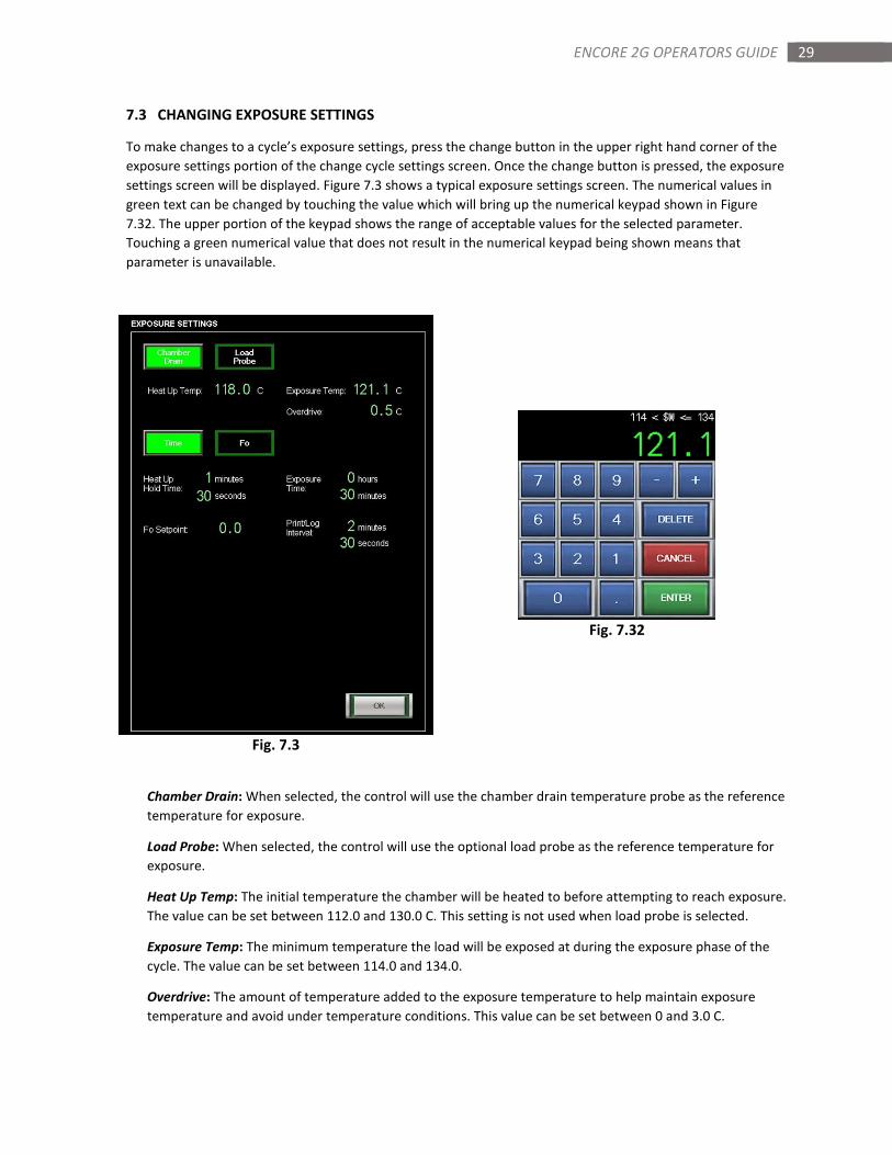
7.3 CHANGING EXPOSURE SETTINGS
To make changes to a cycle’s exposure settings, press the change button in the upper right hand corner of the
exposure settings portion of the change cycle settings screen. Once the change button is pressed, the exposure
settings screen will be displayed. Figure 7.3 shows a typical exposure settings screen. The numerical values in
green text can be changed by touching the value which will bring up the numerical keypad shown in Figure
7.32. The upper portion of the keypad shows the range of acceptable values for the selected parameter.
Touching a green numerical value that does not result in the numerical keypad being shown means that
parameter is unavailable.
Fig. 7.32
Fig. 7.3
Chamber Drain: When selected, the control will use the chamber drain temperature probe as the reference
temperature for exposure.
Load Probe: When selected, the control will use the optional load probe as the reference temperature for
exposure.
Heat Up Temp: The initial temperature the chamber will be heated to before attempting to reach exposure.
The value can be set between 112.0 and 130.0 C. This setting is not used when load probe is selected.
Exposure Temp: The minimum temperature the load will be exposed at during the exposure phase of the
cycle. The value can be set between 114.0 and 134.0.
Overdrive: The amount of temperature added to the exposure temperature to help maintain exposure
temperature and avoid under temperature conditions. This value can be set between 0 and 3.0 C.
30 ENCORE 2G OPERATORS GUIDE
Time: When selected, the control will use time as the measurement method for exposure.
Fo: When selected, the control will use the Fo (F sub-oh) calculations as the measurement for exposure. Fo
can only be selected when load probe has been selected as the reference temperature for exposure.
Heat Up Hold Time: The amount of time the heat up temperature will be held before attempting to reach
exposure. This value can be set between 0 minutes 0 seconds and 10 minutes 59 seconds. This setting is not
used when Fo is selected as the exposure measurement method.
Exposure Time: The amount of time the load will be exposed to the exposure temperature. This value can
be set between 0 hours 1 minute and 6 hours 59 minutes. This setting is not used when Fo is selected as the
exposure measurement method.
Fo Setpoint: The minimum Fo calculation during the exposure phase to achieve sterilization. The Fo is the
number of equivalent minutes of steam sterilization at 121.1 C the load is exposed to. This value can be set
between 1.0 and 20.0. This setting is only used when Fo is selected as the exposure measurement method.
Print/Log Interval: The amount of time between each print line or USB logging during all phases. This
setting can be set between 0 minutes 30 seconds and 10 minutes 59 seconds.
31 ENCORE 2G OPERATORS GUIDE
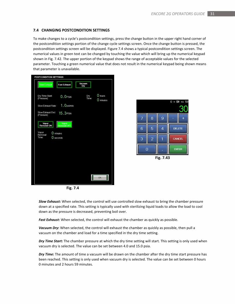
7.4 CHANGING POSTCONDITION SETTINGS
To make changes to a cycle’s postcondition settings, press the change button in the upper right hand corner of
the postcondition settings portion of the change cycle settings screen. Once the change button is pressed, the
postcondition settings screen will be displayed. Figure 7.4 shows a typical postcondition settings screen. The
numerical values in green text can be changed by touching the value which will bring up the numerical keypad
shown in Fig. 7.42. The upper portion of the keypad shows the range of acceptable values for the selected
parameter. Touching a green numerical value that does not result in the numerical keypad being shown means
that parameter is unavailable.
Fig. 7.43
Fig. 7.4
Slow Exhaust: When selected, the control will use controlled slow exhaust to bring the chamber pressure
down at a specified rate. This setting is typically used with sterilizing liquid loads to allow the load to cool
down as the pressure is decreased, preventing boil over.
Fast Exhaust: When selected, the control will exhaust the chamber as quickly as possible.
Vacuum Dry: When selected, the control will exhaust the chamber as quickly as possible, then pull a
vacuum on the chamber and load for a time specified in the dry time setting.
Dry Time Start: The chamber pressure at which the dry time setting will start. This setting is only used when
vacuum dry is selected. The value can be set between 4.0 and 15.0 psia.
Dry Time: The amount of time a vacuum will be drawn on the chamber after the dry time start pressure has
been reached. This setting is only used when vacuum dry is selected. The value can be set between 0 hours
0 minutes and 2 hours 59 minutes.
32 ENCORE 2G OPERATORS GUIDE
Slow Exhaust Rate: The controlled rate in psia per minute that the control attempts to exhaust the
chamber pressure. This setting is only used when slow exhaust is selected. The value can be set between
0.5 and 1.5 psia/minute.
Slow Exhaust End: The pressure at which the slow exhaust phase will end and the control transitions to the
equalization phase. This setting is only used when slow exhaust is selected. The value can be set between
14.5 and 16.5 psia.
Vapor Removal On/Off: When set on, the vapor removal phase will attempt to remove vapor from the
chamber after the door is unsealed. This setting is not available when vacuum dry is selected.
Vapor Removal Time: The amount of time the control will attempt to remove vapor from the chamber. This
setting is not available when vacuum dry is selected. The value can be set between 0 minutes 0 seconds and
9 minutes 59 seconds.
33 ENCORE 2G OPERATORS GUIDE
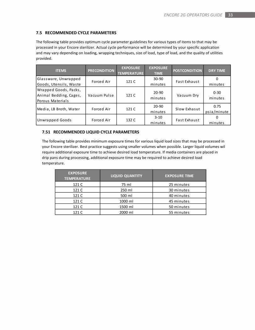
7.5 RECOMMENDED CYCLE PARAMETERS
The following table provides optimum cycle parameter guidelines for various types of items to that may be
processed in your Encore sterilizer. Actual cycle performance will be determined by your specific application
and may vary depending on loading, wrapping techniques, size of load, type of load, and the quality of utilities
provided.
7.51 RECOMMENDED LIQUID CYCLE PARAMETERS
The following table provides minimum exposure times for various liquid load sizes that may be processed in
your Encore sterilizer. Best practice suggests using smaller volumes when possible. Larger liquid volumes wil
require additional exposure time to achieve desired load temperature. If media containers are placed in
drip pans during processing, additional exposure time may be required to achieve desired load
temperature.
ITEMS PRECONDITIONEXPOSURE
TEMPERATURE
EXPOSURE
TIMEPOSTCONDITION DRY TIME
Glassware, Unwrapped
Goods , Utens i ls , WasteForced Ai r 121 C
30-90
minutesFast Exhaust
0
minutes
Wrapped Goods , Packs ,
Animal Bedding, Cages ,
Porous Materia l s
Vacuum Pulse 121 C20-90
minutesVacuum Dry
0-30
minutes
Media , LB Broth, Water Forced Ai r 121 C20-90
minutesSlow Exhasut
0.75
ps ia/minute
Unwrapped Goods Forced Ai r 132 C3-10
minutesFast Exhaust
0
minutes
EXPOSURE
TEMPERATURELIQUID QUANTITY EXPOSURE TIME
121 C 75 ml 25 minutes
121 C 250 ml 30 minutes
121 C 500 ml 40 minutes
121 C 1000 ml 45 minutes
121 C 1500 ml 50 minutes
121 C 2000 ml 55 minutes
34 ENCORE 2G OPERATORS GUIDE
SECTION 8: SPECIALTY CYCLES
The Encore 2G series control comes with 2 user settable Low Temp cycles, a factory set Bowie Dick cycle, and a
factory set Leak Test cycle. This section of the manual describes the functions and applications of these specialty
cycles.
8.1 LOW TEMP CYCLE
Low temp cycles are for any cycles with an exposure temperature of less than 115 degrees Celsius. To run a low
temp cycle, select one of the two Low Temp buttons on the main menu. Many of the settings associated with
typical cycles are used with low temp cycles with exception to precondition settings. The settings are changed
using the same method as the other 20 user settable cycles which can be found in Section 7.
8.2 BOWIE DICK CYCLE
The Bowie Dick cycle is used in conjunction with a Bowie Dick test pack. The cycle is factory set and cannot be
changed. To run the cycle, place a test pack in an empty chamber on the lowest shelf above the drain. Select
the Bowie Dick cycle from the main menu and start the cycle.
8.3 LEAK TEST CYCLE
The Leak Test cycle is used to test the air-tight integrity of the sterilizer’s chamber and piping components. The
test exposes the chamber and piping to vacuum conditions and measures how much vacuum is lost over a
period of time. The cycle is factory set and cannot be changed. The test consists of preconditioning pulses, a 10
minute evacuation and a 10 minute vacuum hold time. At the completion of that hold time, a leak rate is
displayed on the main screen. An acceptable leak rate would be less than 0.3 PSIA/10 min.
35 ENCORE 2G OPERATORS GUIDE
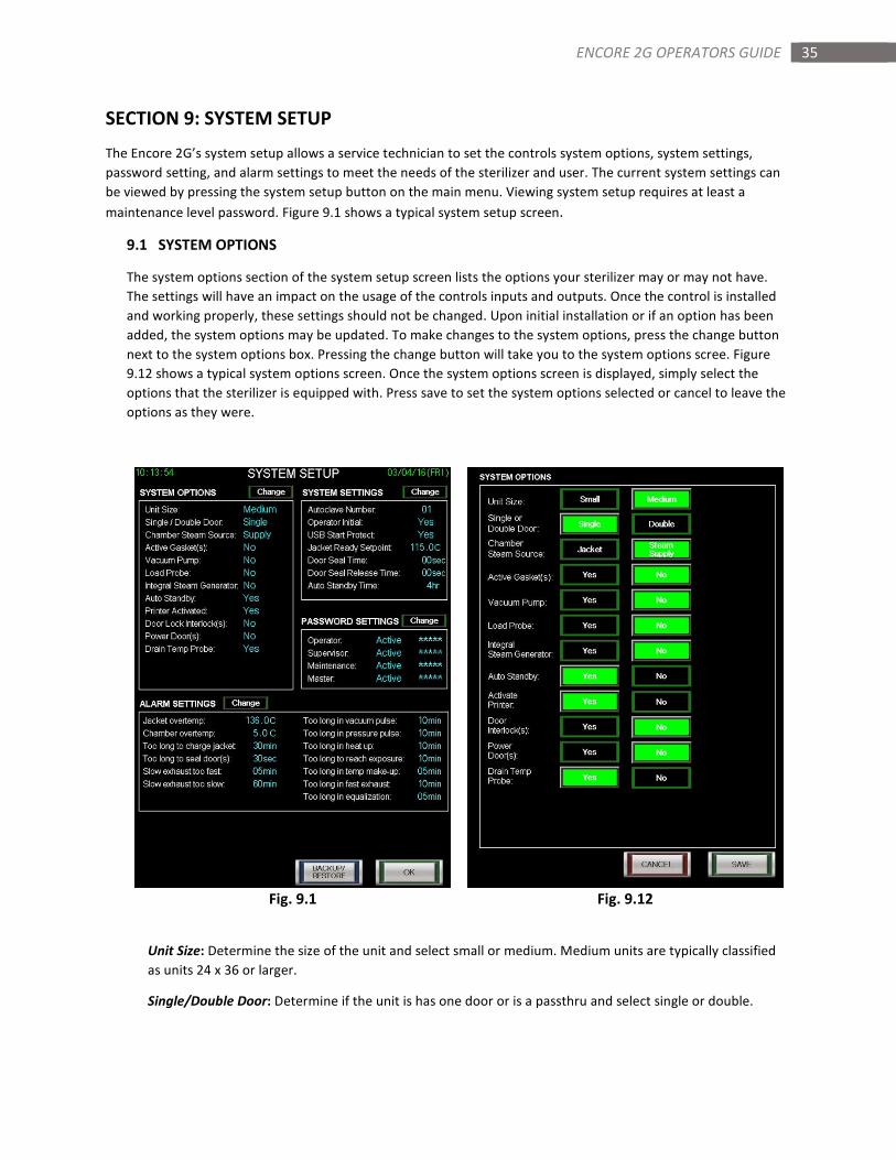
SECTION 9: SYSTEM SETUP
The Encore 2G’s system setup allows a service technician to set the controls system options, system settings,
password setting, and alarm settings to meet the needs of the sterilizer and user. The current system settings can
be viewed by pressing the system setup button on the main menu. Viewing system setup requires at least a
maintenance level password. Figure 9.1 shows a typical system setup screen.
9.1 SYSTEM OPTIONS
The system options section of the system setup screen lists the options your sterilizer may or may not have.
The settings will have an impact on the usage of the controls inputs and outputs. Once the control is installed
and working properly, these settings should not be changed. Upon initial installation or if an option has been
added, the system options may be updated. To make changes to the system options, press the change button
next to the system options box. Pressing the change button will take you to the system options scree. Figure
9.12 shows a typical system options screen. Once the system options screen is displayed, simply select the
options that the sterilizer is equipped with. Press save to set the system options selected or cancel to leave the
options as they were.
Fig. 9.1 Fig. 9.12
Unit Size: Determine the size of the unit and select small or medium. Medium units are typically classified
as units 24 x 36 or larger.
Single/Double Door: Determine if the unit is has one door or is a passthru and select single or double.
36 ENCORE 2G OPERATORS GUIDE
Chamber Steam Source: Determine if the unit feeds the chamber steam from the jacket and select jacket or
steam supply.
Active Gasket(s): Determine if the unit has an active gasket and select yes or no.
Vacuum Pump: Determine if the unit has a vacuum pump and select yes or no.
Load Probe: Determine if the unit is equipped with a load probe and select yes or no.
Integral Steam Generator: Determine if the unit is equipped with an integral steam generator (typically
only on small units) and select yes or no.
Auto Standby: Determine if the auto standby function is to be used and select yes or no. Auto standby
automatically turns the control to the standby screen after a set amount of time of inactivity.
Activate Printer: Determine if the unit is equipped with a printer or if the printer is to be used and select
yes or no.
Door Interlocks: Determine if the unit is equipped with door interlocks and select yes or no. Door interlocks
are typically found on units double door units with a bioseal.
Power Door(s): Determine if the unit is equipped with power doors and select yes or no.
Drain Temp Probe: Determine if the unit is equipped with a drain temperature probe and select yes or no.
37 ENCORE 2G OPERATORS GUIDE
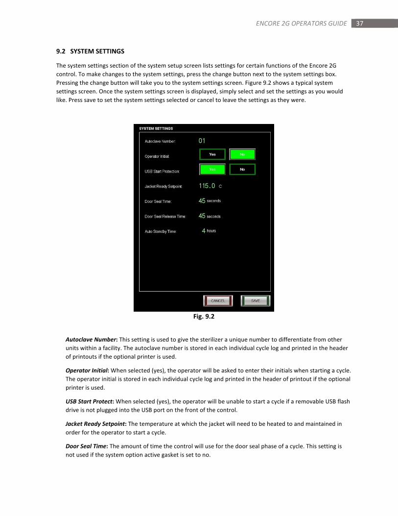
9.2 SYSTEM SETTINGS
The system settings section of the system setup screen lists settings for certain functions of the Encore 2G
control. To make changes to the system settings, press the change button next to the system settings box.
Pressing the change button will take you to the system settings screen. Figure 9.2 shows a typical system
settings screen. Once the system settings screen is displayed, simply select and set the settings as you would
like. Press save to set the system settings selected or cancel to leave the settings as they were.
Fig. 9.2
Autoclave Number: This setting is used to give the sterilizer a unique number to differentiate from other
units within a facility. The autoclave number is stored in each individual cycle log and printed in the header
of printouts if the optional printer is used.
Operator Initial: When selected (yes), the operator will be asked to enter their initials when starting a cycle.
The operator initial is stored in each individual cycle log and printed in the header of printout if the optional
printer is used.
USB Start Protect: When selected (yes), the operator will be unable to start a cycle if a removable USB flash
drive is not plugged into the USB port on the front of the control.
Jacket Ready Setpoint: The temperature at which the jacket will need to be heated to and maintained in
order for the operator to start a cycle.
Door Seal Time: The amount of time the control will use for the door seal phase of a cycle. This setting is
not used if the system option active gasket is set to no.

38 ENCORE 2G OPERATORS GUIDE
Door Seal Release Time: The amount of time the control will use for the door unseal phase of a cycle. This
setting is not used if the system option active gasket is set to no.
Auto Standby Time: The amount of time the control must be inactive before automatically going to system
standby. This setting is not used if the system option auto utility shutdown is set to no.
39 ENCORE 2G OPERATORS GUIDE
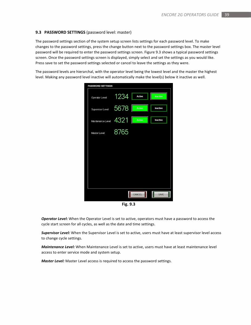
9.3 PASSWORD SETTINGS (password level: master)
The password settings section of the system setup screen lists settings for each password level. To make
changes to the password settings, press the change button next to the password settings box. The master level
password will be required to enter the password settings screen. Figure 9.3 shows a typical password settings
screen. Once the password settings screen is displayed, simply select and set the settings as you would like.
Press save to set the password settings selected or cancel to leave the settings as they were.
The password levels are hierarchal, with the operator level being the lowest level and the master the highest
level. Making any password level inactive will automatically make the level(s) below it inactive as well.
Fig. 9.3
Operator Level: When the Operator Level is set to active, operators must have a password to access the
cycle start screen for all cycles, as well as the date and time settings.
Supervisor Level: When the Supervisor Level is set to active, users must have at least supervisor level access
to change cycle settings.
Maintenance Level: When Maintenance Level is set to active, users must have at least maintenance level
access to enter service mode and system setup.
Master Level: Master Level access is required to access the password settings.
40 ENCORE 2G OPERATORS GUIDE
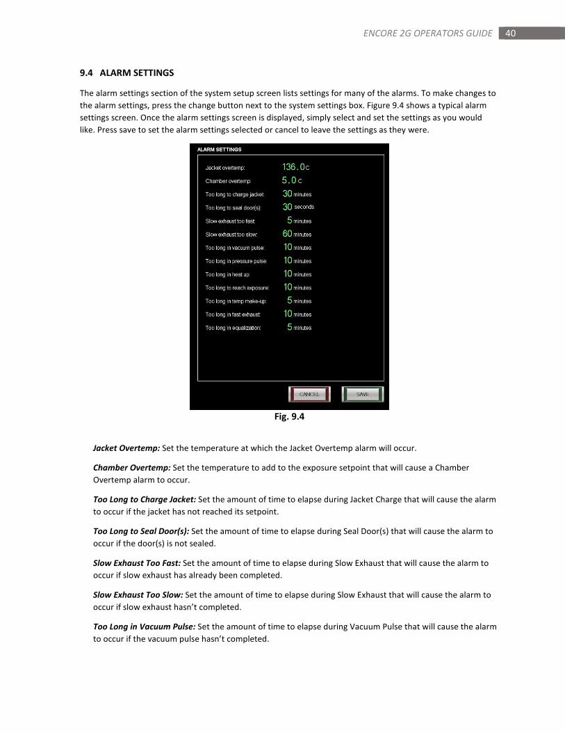
9.4 ALARM SETTINGS
The alarm settings section of the system setup screen lists settings for many of the alarms. To make changes to
the alarm settings, press the change button next to the system settings box. Figure 9.4 shows a typical alarm
settings screen. Once the alarm settings screen is displayed, simply select and set the settings as you would
like. Press save to set the alarm settings selected or cancel to leave the settings as they were.
Fig. 9.4
Jacket Overtemp: Set the temperature at which the Jacket Overtemp alarm will occur.
Chamber Overtemp: Set the temperature to add to the exposure setpoint that will cause a Chamber
Overtemp alarm to occur.
Too Long to Charge Jacket: Set the amount of time to elapse during Jacket Charge that will cause the alarm
to occur if the jacket has not reached its setpoint.
Too Long to Seal Door(s): Set the amount of time to elapse during Seal Door(s) that will cause the alarm to
occur if the door(s) is not sealed.
Slow Exhaust Too Fast: Set the amount of time to elapse during Slow Exhaust that will cause the alarm to
occur if slow exhaust has already been completed.
Slow Exhaust Too Slow: Set the amount of time to elapse during Slow Exhaust that will cause the alarm to
occur if slow exhaust hasn’t completed.
Too Long in Vacuum Pulse: Set the amount of time to elapse during Vacuum Pulse that will cause the alarm
to occur if the vacuum pulse hasn’t completed.
41 ENCORE 2G OPERATORS GUIDE
Too Long in Pressure Pulse: Set the amount of time to elapse during Pressure Pulse that will cause the
alarm to occur if the pressure pulse hasn’t completed.
Too Long in Heat Up: Set the amount of time to elapse during Heating Up 1 that will cause the alarm to
occur if the phase hasn’t completed..
Too Long to Reach Exposure: Set the amount of time to elapse during Heating Up 2 that will cause the
alarm to occur if the chamber temperature has failed to reach exposure setpoint.
Too Long in Temp Make-up: Set the amount of time to elapse during Exposure when the chamber
temperature falls below the exposure setpoint that will cause the alarm to occur.
Too Long in Fast Exhaust: Set the amount of time to elapse during Fast Exhaust that will cause the alarm to
occur if fast exhaust has not completed.
Too Long in Equalization: Set the amount of time to elapse during Equalization that will cause the alarm to
occur if equalization has not completed.
42 ENCORE 2G OPERATORS GUIDE
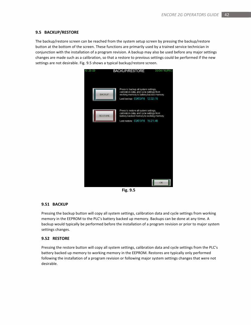
9.5 BACKUP/RESTORE
The backup/restore screen can be reached from the system setup screen by pressing the backup/restore
button at the bottom of the screen. These functions are primarily used by a trained service technician in
conjunction with the installation of a program revision. A backup may also be used before any major settings
changes are made such as a calibration, so that a restore to previous settings could be performed if the new
settings are not desirable. Fig. 9.5 shows a typical backup/restore screen.
Fig. 9.5
9.51 BACKUP
Pressing the backup button will copy all system settings, calibration data and cycle settings from working
memory in the EEPROM to the PLC’s battery backed up memory. Backups can be done at any time. A
backup would typically be performed before the installation of a program revision or prior to major system
settings changes.
9.52 RESTORE
Pressing the restore button will copy all system settings, calibration data and cycle settings from the PLC’s
battery backed up memory to working memory in the EEPROM. Restores are typically only performed
following the installation of a program revision or following major system settings changes that were not
desirable.
43 ENCORE 2G OPERATORS GUIDE
SECTION 10: SERVICE MODE
The Encore 2G’s service mode allows a service technician to test outputs, inputs, analog readings and perform
calibration procedures. Service mode is accessed from the main menu and may require a password. This section of
the manual will describe the screens and functions of the screens found in service mode.
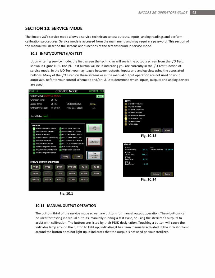
10.1 INPUT/OUTPUT (I/O) TEST
Upon entering service mode, the first screen the technician will see is the outputs screen from the I/O Test,
shown in Figure 10.1. The I/O Test button will be lit indicating you are currently in the I/O Test function of
service mode. In the I/O Test you may toggle between outputs, inputs and analog view using the associated
buttons. Many of the I/O listed on these screens or in the manual output operation are not used on your
autoclave. Refer to your control schematic and/or P&ID to determine which inputs, outputs and analog devices
are used.
Fig. 10.13
Fig. 10.14
Fig. 10.1
10.11 MANUAL OUTPUT OPERATION
The bottom third of the service mode screen are buttons for manual output operation. These buttons can
be used for testing individual outputs, manually running a test cycle, or using the sterilizer’s outputs to
assist with calibration. The buttons are listed by their P&ID designation. Touching a button will cause the
indicator lamp around the button to light up, indicating it has been manually activated. If the indicator lamp
around the button does not light up, it indicates that the output is not used on your sterilizer.
44 ENCORE 2G OPERATORS GUIDE
10.12 OUTPUTS
The outputs listed in this view are listed by their P&ID designation. The outputs description is also listed
with the designation. The indicator lamp next to the output designation indicates whether the PLC has
activated that output. If an output has been manually activated and the output indicator does not light up,
it indicates the PLC did not activate the output. In most cases, an output that is manually activated but does
not turn on the associated output, can be attributed to a safety protection. For instance, if the steam to
chamber valve is manually activated, but the door is not closed, the output indicator for the valve will not
light up and the valve will not be actuated.
10.13 INPUTS
The inputs listed in this view are listed by their P&ID designation. The inputs description is also listed with
the designation. The indicator lamp next to the output designation indicates whether the PLC recognizes
the input as open (not lit) or closed (lit). Figure 10.13 shows a typical view of the inputs window.
10.14 ANALOG
The analog readings listed in this view are listed by their P&ID designation. The description is also listed
with the designation. The readings shown next to the analog devices are their calibrated readings. An
analog device reading 0.0 indicates the device is most likely not used. Figure 10.14 shows a typical view of
the analog devices window.
NOTE: If an analog module error alarm occurs, the analog view will display a red indicator lamp next to the
device that has caused the error. In most cases, it’s caused by the device being unplugged.
45 ENCORE 2G OPERATORS GUIDE
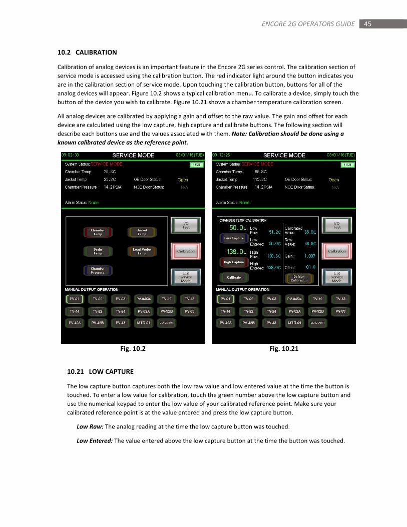
10.2 CALIBRATION
Calibration of analog devices is an important feature in the Encore 2G series control. The calibration section of
service mode is accessed using the calibration button. The red indicator light around the button indicates you
are in the calibration section of service mode. Upon touching the calibration button, buttons for all of the
analog devices will appear. Figure 10.2 shows a typical calibration menu. To calibrate a device, simply touch the
button of the device you wish to calibrate. Figure 10.21 shows a chamber temperature calibration screen.
All analog devices are calibrated by applying a gain and offset to the raw value. The gain and offset for each
device are calculated using the low capture, high capture and calibrate buttons. The following section will
describe each buttons use and the values associated with them. Note: Calibration should be done using a
known calibrated device as the reference point.
Fig. 10.2 Fig. 10.21
10.21 LOW CAPTURE
The low capture button captures both the low raw value and low entered value at the time the button is
touched. To enter a low value for calibration, touch the green number above the low capture button and
use the numerical keypad to enter the low value of your calibrated reference point. Make sure your
calibrated reference point is at the value entered and press the low capture button.
Low Raw: The analog reading at the time the low capture button was touched.
Low Entered: The value entered above the low capture button at the time the button was touched.
46 ENCORE 2G OPERATORS GUIDE
10.22 HIGH CAPTURE
The high capture button captures both the high raw value and high entered value at the time the button is
touched. To enter a high value for calibration, touch the green number above the high capture button and
use the numerical keypad to enter the high value of your calibrated reference point. Make sure your
calibrated reference point is at the value entered and press the high capture button.
High Raw: The analog reading at the time the high capture button was touched.
High Entered: The value entered above the high capture button at the time the button was touched.
10.23 CALIBRATE
The calibrate button uses the information collected from the low capture and high capture to calculate the
gain and offset to apply to the devices raw value. After touching the calibrate button, a window will pop up
asking if you wish to use the low and high values you entered to calibrate the device. Touching no will
cancel the calibration. Touching yes will calculate the gain and offset using the high and low values entered.
Calibrated Value: The analog reading with the gain and offset applied.
Raw Value: The raw analog reading with no gain or offset applied.
10.24 DEFAULT CALIBRATION
The default calibration button applies a value of 1.000 to the gain and 0.00 to the offset. Doing this, makes
the calibrated value and raw value the same. After touching the default calibration buttons, a window will
pop up asking if you wish to apply these default values to the gain and offset. Touching no will cancel this
application. Touching yes will apply the default values to the gain and offset. Default calibration is typically
used when the accuracy of the analog device is not crucial.
10.25 ENTERING GAIN AND OFFSET DIRECTLY
The Encore 2G gives the technician the ability to bypass the low capture, high capture and calibrate process
if they choose to calculate the gain and offset on their own or wish to simply make a small change to the
gain and offset. Touching the value next to the gain or offset will display a numerical keypad. Key in your
value and press enter to change the current value.
Gain = (High entered minus Low entered) divided by (High raw minus Low raw)
Offset = (Low raw) minus (Gain multiplied by Low entered)
IMPORTANT: The gain and offset correction will only give an accurate correct reading between our two
known points (low and high). Applying the gain and offset to points lower than the low value point or higher
than the high value point will not produce an accurate reading.
Recommended