High Power Solid State Advances in Technology
Paulo Correa, Chief Technology Officer
Electronic Warfare Europe
05/13-15/2019
Empower RF Systems
Empower RF Systems, Inc. Slide 2
• Why This Topic?
• Technology Enablers
• Myth Busting
• Illustrations of Technology Advancements– Frequency Hopping GPS Denial
– Digital At Nominal Power
– Pulse Shaping
– Adaptive Digital Pre-Distortion Concept
– Solid State Higher Power Solution (S, C and X band)
– Rack mechanical design
– Relevant illustrations – deployed systems
• Conclusions
High Power Solid State Advances in Technology

Empower RF Systems, Inc. Slide 3
Why this Topic?
Responding to what’s driving EW and Threat Simulation Requirements
Developments across the electromagnetic spectrum - increasingly complex waveforms and signals environment that requires more than a “dumb” PA.
Requests to support size constrained applications and requirements for mobility.
Aging infrastructure and obsolescence issues facing the EW and radar design community that uses conventional amplifier designs (including TWT) while trying to implement updates elsewhere.
Requests for interoperability of a standard platform (hardware & software) across multiple applications.
Requirements to “scale” power, bandwidth, pulse widths for dealing with emerging threats.

Empower RF Systems, Inc. Slide 4
• Developments in ADC/DACs, Fiber and Processors
• Affordable high speed ADCs and DACs– Allows for coherently digitizing RMS and envelope signals at the input and output of HPA.
– Allows full digital peak detection to measure input power, forward and reverse power.
– Measurement of peak and RMS allows for operation with any kind of modulated signal.
– Measurement of multiple HPA parameters including efficiency and P1dB.
• Use of fiber optics to interconnect mother board to front and rear panels*– Fiber Optic interconnection between front panel, rear panel and motherboard
– Fast data transfer.
– No wires in these assemblies other than DC voltages.
– Radiated emission significantly reduced for enhanced EMC performance.
• New SoC allows high level of integration– Microprocessor and FPGA integrated in the same fabric allows an effective combination
of signal processing, command and control.
– Flexible and scalable platform – adds capacity to include new features.
– Efficiency on size and weight and, at the same time, adding computational power
• 100X increase in computational power in the same footprint with existing hardware
Technology Enablers
* US Patent pending

Empower RF Systems, Inc. Slide 5
• MYTH: pulse width and duty cycle limitations
– A technology enabled SSPA allows user to operate at full power with 500µs pulse width and 20% duty cycle.
– Digital signal processing allows operation in CW with the appropriate back off.
– Duty cycle protection operates at leading edge of the pulse or at the waveform energy.
• MYTH: Solid state can have jitter when combining multiple PAs in parallel
– Architecture with technology enabled SSPA’s guarantees minimum jitter.
– Common blanking synchronizes on/off of all Pas.
• MYTH: System performance can only be enhanced at the signal generator
– Output power controlled by a technology enabled SSPA keeps the exciter at a constant setting.
– Pulse correction at MW/RF chain – releases computational capability of the integrated system controller to optimize the mission.
“Myth Busting” with technology enabled SSPA’s

Empower RF Systems, Inc. Slide 6
Technology Enabled, Multi-mode / Interoperable Power Amplifiers
• Multimode Power Amplifier is an amplifier that can operate in all modes required for its application:
– Any type of detector– Any type of Output Power Management– Any type of Modulation– Efficient in any mode and maximum power in any mode
• Interoperable Power Amplifier is an amplifier that requires no change in hardware to operate in any mode.
– Can operate in CW and in Pulse with the same peak power w/o any HW change.– Can detect RMS or Peak power w/o HW change.– Can change from manual gain control (MGC) to automatic gain control (AGC) to automatic
level control (ALC).– Can operate in Multi-carrier, frequency hopping, barrage, digital modulation, AM
modulation Pulse mode and Pulse modulation in any Output Power Management.– Can have the same API and user experience.
• Why Do We Care?– This is a single unit capable of Multi-Domain applications.– Designed to stay ahead of the increasing complexities of the signals environment.– Higher efficiency and better utilization of size and weight.

Empower RF Systems, Inc. Slide 7
Technology Advancement- Frequency Hopping GPS Denial
Data taken from a 1 – 3 GHz, 1 kW HPAblanking not required – 10 microsecond hopping between L1 and L2
Model 2170-003
Empower RF Systems, Inc. Slide 8
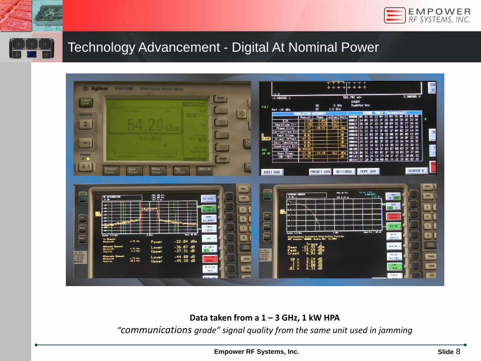
Technology Advancement - Digital At Nominal Power
Data taken from a 1 – 3 GHz, 1 kW HPA
“communications grade” signal quality from the same unit used in jamming

Empower RF Systems, Inc. Slide 9
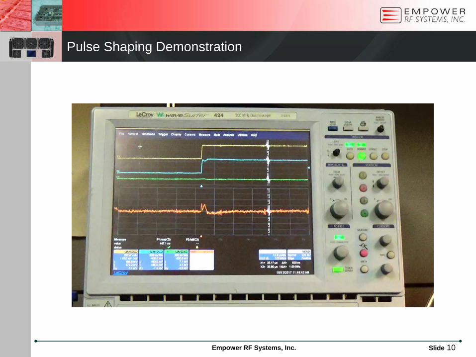
Technology Advancement - Pulse Shaping
Yellow trace is the inputBlue trace is the outputGreen trace is the correctionOrange trace is the error
Left picture is the wiggle in the pulse cause by the PA
Right picture is applying the correction you can see thewiggle is almost canceled.
Pulse correction to enhance the reproduction of the recorded threat
Empower RF Systems, Inc. Slide 10
Pulse Shaping Demonstration
Empower RF Systems, Inc. Slide 11
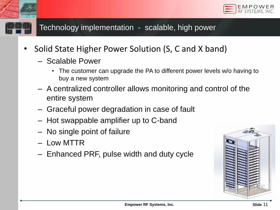
• Solid State Higher Power Solution (S, C and X band)
– Scalable Power
• The customer can upgrade the PA to different power levels w/o having to
buy a new system
– A centralized controller allows monitoring and control of the
entire system
– Graceful power degradation in case of fault
– Hot swappable amplifier up to C-band
– No single point of failure
– Low MTTR
– Enhanced PRF, pulse width and duty cycle
Technology implementation - scalable, high power

Empower RF Systems, Inc. Slide 12
Rack mechanical design
14 Amplifiers Units per rack
Control System: present only at the left rack, display can be an
industrial PC
14 Circuit breakers for
individual PAs
Rack Rear viewRack waveguide combiner

Slide 13
ww
w.E
mp
ow
erR
F.c
om
ww
w.E
mp
ow
erR
F.c
om
Technology enabled SSPA’s – some illustrations of interest
Slide 13
Unmanned Remote Nodes
Central Node
2 MHz – 6 GHz coverage
multi-mode, multi-mission
threat simulator network
20 MHz – 6 GHz coverage - output power up to 1 KW
multi-mode, multi-mission (EW and communications)
Threat Simulators
150 MHz to 450 MHz, 12 KW Pulse
2.9 GHz to 3.5 GHz, 8 & 10 KW Pulse
5.2 GHz to 5.9 GHz, 8 KW Pulse
9.2 GHz to 10 GHz, 8 KW Pulse
scalable power
“system of systems”

Empower RF Systems, Inc. Slide 14
Conclusion
“we are moderately prepared for a low end fight, but we have work to do to prepare for a high end fight”
• Threat sophistication is advancing rapidly which makes a flexible, technology enabled HPA essential for EW.
• Technology enabled SSPA brings computing power that has traditionally resided only in a system controller.
• Scalability means shorter time to deployment and an adaptable infrastructure for new requirements.
• Standards based operating systems with technology enabled SSPA’s are achievable.
• Leap ahead capabilities in SWaP and SSPA operational adaptability can be brought to this fight now.
• Low speed response kills …
Channelizer and De-channelizer are N channel Polyphase Filter Banks with 2x interpolation.
The prototype filter is such that the 3 dB roll-off point of the filter is right at the channel edge.
Ch
an
ne
lize
r
DAC
De
cha
nn
eliz
er
ADC
Ch
an
ne
lizer
DPD Cores
ADPD PA
CPLRINPUT OUTPUT
Complex
Magnitude
Index
Mapper
Fractional
DelayAdaptive Algorithm
LUT
Delay
Adjust
Input Output
Feedback
The Resulting Leap Ahead Capability• The elimination of external filtering and associated
insertion loss improving deployment SWaP and cost.• A single amplifier can perform complex jamming and
communications simultaneously
Forward Looking: Adaptive Digital Pre-Distortion
Recommended