Platform Trailers
Operation and Service Manual

Contents Page 3
CONTENTS
Contents ............................................................................................................ 3 Introduction ...................................................................................................... 4
Safety Information ....................................................................................... 4 Decals ........................................................................................................ 5
Operation .......................................................................................................... 7 Normal Trailer Use ...................................................................................... 7 Pre-Trip Inspection Checklist ...................................................................... 8 Coupling and Uncoupling Procedures ......................................................... 9
Coupling Preparation ............................................................................ 9 Coupling Procedure .............................................................................. 9 Uncoupling Preparation .......................................................................10 Uncoupling Procedure .........................................................................10
Sliding Axle Relocation Procedure .............................................................11 Load Distribution ........................................................................................12
Overloading .........................................................................................12 Load Distribution Ratings .....................................................................13
Flatbed Trailer Anchor Points .....................................................................14 Hauling Single Coils .............................................................................17
Preventive Maintenance ..................................................................................18 Weekly Inspection ......................................................................................18
Component Operation .....................................................................................19 General Instructions ...................................................................................19 Landing Gear (2-Speed) ............................................................................19
Lubrication ...........................................................................................20 Suspensions ..............................................................................................20
Air Suspensions ...................................................................................21 Shock Absorbers .................................................................................21
Air Controls ................................................................................................22 Height Control Valve ............................................................................22
Disc Wheels ...............................................................................................23 Changing Flat Tire ...............................................................................23
Service .............................................................................................................24 Preventive Maintenance ............................................................................24
Weekly Inspection ................................................................................24 Monthly Inspection ...............................................................................24
Component Operating Instructions .............................................................25 Visual Inspection..................................................................................25 Trailer Axle Alignment ..........................................................................26 Brakes .................................................................................................28 ABS .....................................................................................................29 Wheel Bearings ...................................................................................32 Wheel Hubs and Seals ........................................................................33
Troubleshooting ..............................................................................................35 Schematics ......................................................................................................37
Electrical ....................................................................................................37 NHTSA Information ..........................................................................................40 East Five Year Limited Warranty ....................................................................43
Page 4 Safety Information
INTRODUCTION
This manual
Describes the proper procedures that must be considered prior to operating any of East Manufacturing Corporation’s platform trailers.
Contains safety information, instructions, and preventive maintenance checks that the operator should perform periodically.
Should be kept with the trailer at all times.
East manuals are available online at www.eastmfg.com
East reserves the right to change its products and documents without notice.
Safety Information This manual addresses safety information, pre-trip inspections, preventive maintenance, guide for proper loading techniques and general information regarding East platform trailers. Instructions are given covering the operation and service of East platform trailers. Direct any questions regarding this manual to East.
IMPORTANT
Read this manual carefully prior to loading or towing the East trailer.
Do NOT attempt to operate or service the trailer until instructions and safety precautions are read and completely understood.
Operate and service the East trailers within the operating limits outlined in this manual. When operating East trailers, basic safety precautions should always be followed.
If problems arise, reference Troubleshooting in the back of this manual, contact a dealer, or East. Help is also available at www.eastmfg.com.
For all maintenance requirements, use only genuine East authorized
parts.
Important advisories are indicated as follows:
A WARNING! Advisory specifies a procedure that must be followed exactly. Personal injury can occur if the advisory is not followed.
A CAUTION! Advisory specifies a procedure that must be followed exactly. Damage to equipment or components can occur if the advisory is not followed.
Note: A Note can contain information that can increase the longevity of the trailer. A Note can also provide information that will enable quicker
and easier servicing.
Intr
od
uc
tio
n
Decals Page 5
Decals Decals are an important part of safe trailer operation. Decals address safe operation and maintenance of the trailer, as well as regulation information to maintain compliance with state and federal regulations.
Prior to operation, locate and review the information of each decal on the trailer.
The decals shown below represent examples of the content and location of East’s standard decals at the time of printing and
manufacturing of the trailer. The number, placement, and type of decals are not limited to those shown. Note that decals may be updated or replaced by other decals. Upon receipt of the trailer document what decals are on it by recording the decal part numbers located at the bottom of each decal. If any safety decals are missing or get damaged, contact East for replacement at no cost to you.
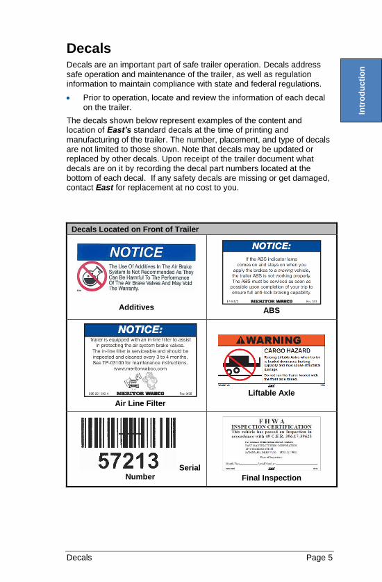
Decals Located on Front of Trailer
Additives
ABS
Air Line Filter
Liftable Axle
Serial Number
Final Inspection
Intr
od
uc
tio
n
Page 6 Decals
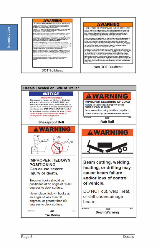
DOT Bulkhead
Non DOT Bulkhead
Decals Located on Side of Trailer
Shakeproof Bolt
Rub Rail
Tie Down
Beam Warning
Dec
als
Intr
od
uc
tio
n
Normal Trailer Use Page 7
OPERATION
Normal Trailer Use East trailers are designed for operation within the legal highway speed limits on reasonable road surfaces for the type of service it was built to perform in accordance with the following:
1. The trailer was built to carry cargo within the limitations of two weight ratings listed on the VIN plate. The VIN plate is located on the main chassis rail, road side, directly to the rear of the landing gear. These weight ratings are:
- GAWR (gross axle weight rating)—The structural capability
of the lowest rated member of the running gear components: suspension and spring system, hubs, wheels, drums, rims, bearings, brakes, axles, or tires.
- GVWR (gross vehicle weight rating)—The structural
capability of the trailer when supported by the upper coupler assembly and axles with the load uniformly distributed throughout the cargo space.
CAUTION! The maximum load indicated on the VIN plate may or may NOT be a legal load on the highway you plan to use.
2. This trailer will carry a total payload equal to the GVWR less the weight of the trailer. The load must be uniformly distributed and not exceed the GAWR. Consult specific trailer model literature for concentrated load ratings or contact East. Recommended payload distributions are shown in Figure 2 through Figure 4.
3. The cargo should be properly loaded, blocked, and braced to prevent load shifts and to comply with the following sections of the Department of Transportation Federal Motor Carriers Safety Regulation, Subpart 1—Protection Against Shifting or Falling Cargo:
- Section 393.100—General Rules for Protecting Against Shifting or Falling Cargo
- Section 393.102—Securement Systems
- Section 393.104—Blocking and Bracing
- Section 393.106—Front End Structure
- Section 393.116—Logs
- Section 393.118—Dressed Lumber
- Section 393.120—Metal Coils
- Section 393.124—Concrete Pipe
WARNING!
Walk carefully on the trailer. The deck may be slippery. Enter and leave the trailer only from a dock or substantial ladder as high as the trailer floor. Advise others of these precautions.
Operation of this trailer outside the limitation of this manual is against federal law and will void any responsibility of East for any of its results.
Op
era
tion
Page 8
Pre-Trip Inspection Checklist
CAUTION! East platform trailers must be operated ONLY by trained and qualified professional drivers.
Driver Pre-trip inspections must be completed before the first trip of each day and each subsequent trip during the day. Each pre-trip inspection will visually inspect for deficiencies, including the following:
Inspect for any apparent damage. Verify that all lights function properly. Look for oil, water, or fuel leaks. Verify that the spare tire is secure in the carrier to avoid tire carrier
damage. Be sure the tire carrier is securely bolted. Verify that the kingpin is engaged and locked within the fifth wheel. Examine the support legs (landing gear) for proper road clearance
and ensure the crank handle is securely stowed. Visually inspect all springs. Check that there is air in each air spring (air suspension) and shock
absorber fasteners are tight. By actuation, verify that the brake system is in proper working order
and listen for air leaks when the brake system is charged. Check the air pressure of all tires. If needed, inflate tires to tire
manufacturer’s recommendations. Check the oil level in the wheel hubs. Check the oil seals for leakage. Check for loose or missing fasteners on fifth wheel plate. Insure Kingpin has zero movement.
Op
era
tio
n
Coupling and Uncoupling Procedures Page 9
Coupling and Uncoupling Procedures
WARNING!
Severe injury or death may occur as a result of failing to properly couple or uncouple trailer. To properly couple or uncouple trailer follow instructions below.
Coupling Preparation 1. Prior to coupling the tractor to the trailer, place blocks securely
behind the rear tires of the trailer. 2. Align the tractor with the trailer. 3. Check the position of the fifth wheel with respect to the trailer
coupler plate to ensure that the fifth wheel is at the proper height. 4. Ensure that the contact with the fifth wheel and the nose of the
trailer is just to the rear of the center of the fifth wheel. 5. Adjust the extension of the support legs to adjust the coupler height
(see page 19).
Note: If the nose of the trailer is too low, and contact with the nose of
the trailer is made at the rear of the fifth wheel, too much force will be required to lift the trailer. The extra force needed to make engagement can result in impact damage to the nose of the trailer. Avoid this ramming technique.
CAUTION! If the nose of the trailer is too high, the kingpin can override the jaws of the fifth wheel resulting in “high hookup” and could damage the fifth wheel mechanism.
Coupling Procedure 1. Once the tractor and trailer are properly aligned, back the tractor
until the fifth wheel coupler jaws engage the kingpin. 2. When the locked engagement has been made, verify a positive
hookup by attempting to move the vehicle forward while the trailer brakes are still applied.
3. Once coupling is complete as described above, A. Attach all air lines B. Ensure correct coupling C. Connect the electrical connection
4. Visually inspect the fifth wheel locking mechanism and verify that the kingpin has been properly positioned within the fifth wheel coupler jaws and that the fifth wheel safety locks are in position.
5. Charge the trailer brakes with air. 6. With the support leg crank in the low gear position, raise the
support legs until ground clearance is achieved (see page 19). 7. With the support legs off the ground, place the support leg crank in
the high gear position to raise the legs to the proper height for ground clearance (see page 19).
8. Stow the crank handle in the high gear position in the bracket provided.
Op
era
tio
n
Page 10 Coupling and Uncoupling Procedures
9. If this procedure has been followed, the trailer brake system has already been actuated and performance checked at the time the coupling check was made.
10. If chocks were used and the air brake system has not been checked, do so at this time.
11. Inspect the electrical coupling 12. Operate the trailer lights by energizing the tractor light switches and
applying the brake. 13. The final check for complete tractor to trailer coupling is made with
the trailer brakes applied. Attempt to move the trailer forward and rearward by tractor power to ensure fifth wheel is locked securely.
Uncoupling Preparation 1. Set the trailer parking brakes. 2. Place chock blocks in front and rear of the wheels of the trailer.
Uncoupling Procedure 1. Lower the support legs with the crank handle in the high gear
position until ground contact is made (see page 19). 2. With the crank handle in the low position, turn the crank handle to
transfer the weight of the trailer from the fifth wheel of the tractor onto the support legs (see page 19).
3. Disconnect the air and electric jumper lines from the trailer. 4. If the tractor is equipped with shutoff cocks for the airlines, close
them before disengaging the glad hands at the front of the trailer. 5. Prepare the fifth wheel for uncoupling by activating the release
handle(s) 6. To ensure disengagement of the trailer, slowly move the tractor
forward until clear of the trailer.
Note: Although the United States Department of Transportation (DOT)
requires trailer automatic parking brakes, chocks are still recommended for safety.
Op
era
tio
n
Sliding Axle Relocation Procedure Page 11
Sliding Axle Relocation Procedure
WARNING!
Crush Hazard Severe Injury or Death may occur as a result of sudden vertical suspension movements that can occur during Axle Sliding. Never place any body part between Wheels and Floor of Trailer.
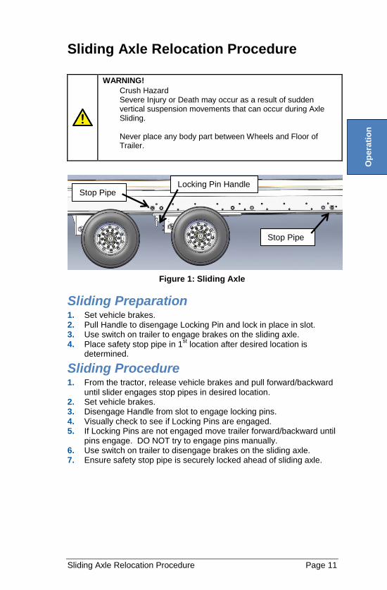
Figure 1: Sliding Axle
Sliding Preparation 1. Set vehicle brakes. 2. Pull Handle to disengage Locking Pin and lock in place in slot. 3. Use switch on trailer to engage brakes on the sliding axle. 4. Place safety stop pipe in 1
st location after desired location is
determined.
Sliding Procedure 1. From the tractor, release vehicle brakes and pull forward/backward
until slider engages stop pipes in desired location. 2. Set vehicle brakes. 3. Disengage Handle from slot to engage locking pins. 4. Visually check to see if Locking Pins are engaged. 5. If Locking Pins are not engaged move trailer forward/backward until
pins engage. DO NOT try to engage pins manually. 6. Use switch on trailer to disengage brakes on the sliding axle. 7. Ensure safety stop pipe is securely locked ahead of sliding axle.
Locking Pin Handle
Stop Pipe
Stop Pipe
Op
era
tio
n
Page 12 Load Distribution
Load Distribution
Overloading
WARNING!
Severe Injury or Death may occur as a result of overloading. In addition, overloading can:
Decrease stability
Increase likelihood of rollovers
Cause rapid tire wear or damage
Deform axle beam and/or spindles
CAUTION! Concentrated loads must span the main beams of the trailer to prevent damage to the trailer deck and siderails.
WARNING!
Severe Injury or Death may occur as a result of improper load distribution. In addition loads with high centers of gravity require extra precaution. A high center of gravity:
Can cause instability
Acts in a levering action; the higher it is, the longer the lever and the greater the force which can develop.
Can overload frame members or truck tires during a sudden stop.
Reduce your speed if pulling a load with a high center of gravity. Should the vehicle stop suddenly, the high center of gravity works forward and rearward, as well as sideward.
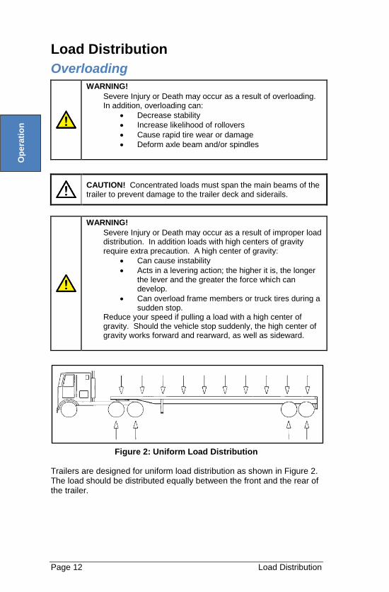
Figure 2: Uniform Load Distribution
Trailers are designed for uniform load distribution as shown in Figure 2. The load should be distributed equally between the front and the rear of the trailer.
Op
era
tio
n
Load Distribution Page 13
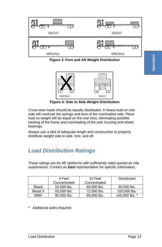
Figure 3: Fore and Aft Weight Distribution
Figure 4: Side to Side Weight Distribution
Cross-wise loads should be equally distributed. A heavy load on one side will overload the springs and tires of the overloaded side. Place load so weight will be equal on the rear tires, eliminating possible twisting of the frame and overloading of the axle housing and wheel bearings.
Always use a skid of adequate length and construction to properly distribute weight side to side, fore, and aft.
Load Distribution Ratings
These ratings are for 48’ platforms with sufficiently rated spread air ride suspensions. Contact an East representative for specific information.
4 Feet Concentrated
10 Feet Concentrated
Distributed
Beast 52,000 lbs. 60,000 lbs. 90,000 lbs.
Beast II 65,000 lbs. 72,000 lbs. 100,000 lbs.
MMX 80,000 lbs. 89,000 lbs. 145,000 lbs. *
* Additional axles required
X
Op
era
tio
n
Page 14 Flatbed Trailer Anchor Points
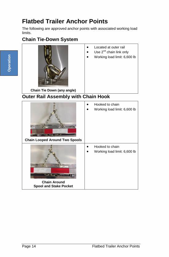
Flatbed Trailer Anchor Points The following are approved anchor points with associated working load limits.
Chain Tie-Down System
Chain Tie Down (any angle)
Located at outer rail
Use 2nd chain link only
Working load limit: 6,600 lb
Outer Rail Assembly with Chain Hook
Chain Looped Around Two Spools
Hooked to chain
Working load limit: 6,600 lb
Chain Around Spool and Stake Pocket
Hooked to chain
Working load limit: 6,600 lb
Op
era
tio
n
Flatbed Trailer Anchor Points Page 15
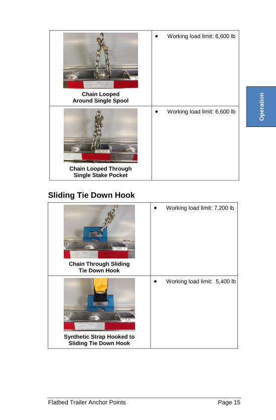
Sliding Tie Down Hook
Chain Through Sliding Tie Down Hook
Working load limit: 7,200 lb
Synthetic Strap Hooked to Sliding Tie Down Hook
Working load limit: 5,400 lb
Chain Looped Around Single Spool
Working load limit: 6,600 lb
Chain Looped Through Single Stake Pocket
Working load limit: 6,600 lb
Op
era
tio
n
Page 16 Flatbed Trailer Anchor Points
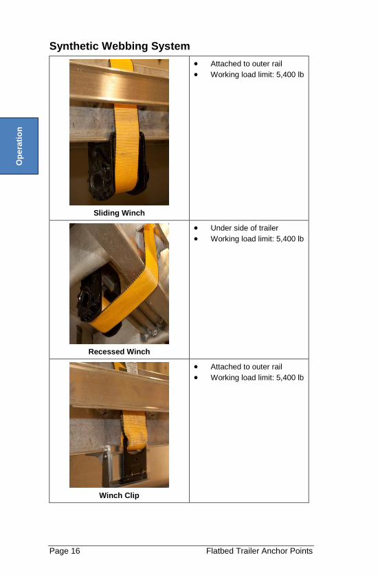
Synthetic Webbing System
Sliding Winch
Attached to outer rail
Working load limit: 5,400 lb
Recessed Winch
Under side of trailer
Working load limit: 5,400 lb
Winch Clip
Attached to outer rail
Working load limit: 5,400 lb
Op
era
tio
n
Flatbed Trailer Anchor Points Page 17
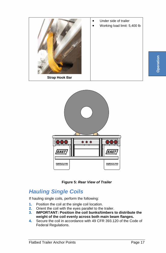
Strap Hook Bar
Under side of trailer
Working load limit: 5,400 lb
Figure 5: Rear View of Trailer
Hauling Single Coils If hauling single coils, perform the following:
1. Position the coil at the single coil location. 2. Orient the coil with the eyes parallel to the trailer. 3. IMPORTANT: Position the coil bunks/timbers to distribute the
weight of the coil evenly across both main beam flanges.
4. Secure the coil in accordance with 49 CFR 393.120 of the Code of Federal Regulations.
Op
era
tio
n
Page 18 Weekly Inspection
PREVENTIVE MAINTENANCE
It is important to perform preventive maintenance inspections to ensure safe operation of the trailer.
Every trailer owner and/or operator should have an organized Trailer Preventive Maintenance program. DOT requires that maintenance records be kept on every commercial highway vehicle.
For helpful publications in setting up and operating a Trailer Preventive Maintenance program, contact:
Truck Trailer Manufacturers Association 7001 Heritage Village Plaza Suite 220 Gainesville, VA 20155 www.ttmanet.org
(703) 549-3010
Weekly Inspection
The operator’s weekly preventive maintenance procedure includes the following:
Inspect for any damage. Verify that all lights function and are in place and not obscured. Lubricate the fifth wheel. Check for loose or missing bolts. Check
Kingpin for tightness Inspect the support leg mounting plates and the bracing for cracks. Visually inspect all air springs and air lines for chafing. Check the brake valves for leaks and ensure proper operation. Check for and remove any foreign material from within the dust
shields. Drain the condensate from the air reservoirs. Check the tire air pressure. Inflate according to tire manufacturers’
recommendations. Verify that the wheel lug nuts are tight. Check the oil level in the wheel hubs to ensure proper wheel
bearing lubrication. Inspect seals/hubcaps for leaks. Grease all Zerk fittings
CAUTION! Maintenance must be performed only by trained and qualified personnel following these instructions and those specified in the component manufacturers’ instruction manuals.
Pre
ve
nta
tiv
e
Ma
inte
na
nce
General Instructions Page 19
COMPONENT OPERATION
General Instructions
CAUTION! East uses high quality components produced by reliable original equipment manufacturers in all of its custom-built trailers. Refer to each component manufacturer’s service manual for specific product information.
Good maintenance practices benefit trailer operators who properly maintain their equipment. Performing recommended cleaning and maintenance procedures saves time and money.
Maintenance for vehicle appearance includes cleaning, brightening, and polishing.
Knowledge of proper usage of recommended materials and compounds is essential for satisfactory results.
Numerous chemical firms provide materials along with instructions for obtaining the best results.
Maintenance performed with various chemical compounds will be similar, but will vary and so be sure to follow the product manufacturer’s instructions.
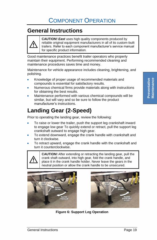
Landing Gear (2-Speed) Prior to operating the landing gear, review the following:
To raise or lower the trailer, push the support leg crankshaft inward to engage low gear To quickly extend or retract, pull the support leg crankshaft outward to engage high gear.
To extend downward, engage the crank handle with crankshaft and turn it clockwise.
To retract upward, engage the crank handle with the crankshaft and turn it counterclockwise.
CAUTION! After extending or retracting the landing gear, pull the crank shaft outward, into high gear, fold the crank handle, and place it in the crank handle holder. Never leave the gears in the neutral position or allow the crank handle to be unsecured.
Figure 6: Support Leg Operation
Pre
ve
nta
tiv
e
Ma
inte
na
nce
Page 20 Suspensions
Lubrication Although the landing gear is greased and packed with high-quality lubricants at the time of manufacture, it may be necessary to periodically lubricate the landing gear to maintain satisfactory performance. Additional lubrication may be needed when support legs are used frequently. Two times a year, or as required by the manufacturer’s service manual, lubricate both support legs through the grease fittings provided.
Suspensions Suspensions for over-the-road operations require periodic inspections to ensure continued safe performance.
The operator should check the following during the pre-delivery inspection and after the first 1,000 miles of operation:
1. The ride is level 2. Trailer is at the specified height. 3. All welds are of acceptable quality. 4. All bolts are securely in place. 5. The articulation of the suspension has no interferences 6. All bolts are at the specified torque.
- Torque: The amount of force with which certain fasteners
(nuts, bolts, etc.) are to be tightened are specified by torque values as noted in foot-pounds (ft-lb).
- A decal is mounted on each East chassis that has the required torque values for the bolted connections of that vehicle.
7. Suspension alignment is correct. Adjust if needed. 8. Check for corrosion buildup between dissimilar metal mating
surfaces that can occur due to de-icing agents being used on the roads. Examples of this include the interfaces between the main beam and the suspension hangers or the main beam and fifth wheel plate.
Pre
ve
nta
tiv
e
Ma
inte
na
nce
Suspensions Page 21
Air Suspensions
Air Springs
In most applications, air springs should last almost indefinitely. However, rubbing, scuffing, or puncturing causes air springs to fail quickly.
If an air spring fails, the vehicle will rest on the internal rubber bumpers, enabling the vehicle to be taken to the next convenient service facility.
The cause of the air spring failure must be determined to avoid reoccurrence
Air Spring Replacement
To replace an air spring,
1. Raise and support the vehicle in a safe manner. 2. If jacks are used, you must use jack stands at the rear corners of
the trailer frame. 3. Ensure all air is drained from bags and disconnect the air lines. 4. Unbolt the damaged air spring from its mount to allow the
replacement spring to be installed.
Shock Absorbers Shock absorbers absorb energy to prevent suspension oscillation. They are also used as rebound stops in most air suspensions. Air springs can be pulled apart if their stroke is not restrained by the shock absorber or some other device.
In many operations, the air suspension functions well without shock absorbers. As a result, unless operational problems are detected, immediate replacement of shock absorbers may not be necessary.
Shock Absorber Replacement
When necessary to replace the shock absorbers,
1. Remove the end fasteners. 2. Secure the new shock absorber with the correct size and grade of
bolts and lock nuts. 3. Ensure replacement shock absorbers
A. Match the original specifications for performance range. B. Comply with suspension manufacturer’s recommendations.
- Because your suspension may have unique travel requirements, the shock absorber used will probably have its own special characteristics.
CAUTION! Do NOT lift the trailer without the shock absorbers in place. Damage will likely occur to the air springs because of over extension.
CAUTION! Do NOT exceed 5 mph when traveling in reverse and aggressively apply brakes. Separation of the shock absorber could result.
Pre
ve
nta
tiv
e
Ma
inte
na
nce
Page 22 Air Controls
Air Controls Many types of air controls are available for use with the suspension system. The most common systems automatically regulate the design height by controlling the air pressure supplied to the air springs. Design height is the distance from the center line of the axle to the underside of the chassis at the location where the height control valve is located.
When an air suspension is used in conjunction with other suspensions, such as the mechanical leaf spring type, an operator-controlled pressure regulator may be used. This operator-controlled regulator allows the operator to select the appropriate amount of air pressure to equalize the axle loadings.
Note the following about air controls:
If lift axles are installed, other special control circuits and components must be added to properly coordinate this independent suspension with the others.
All-air suspensions on the trailer operate from its isolated compressed air supply.
In addition to providing pressure for equalized axle loadings, the air suspension is also capable of changing the suspension height within a limited range.
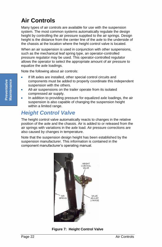
Height Control Valve The height control valve automatically reacts to changes in the relative position of the axle and the chassis. Air is added to or released from the air springs with variations in the axle load. Air pressure corrections are also caused by changes in temperature.
Note that the suspension design height has been established by the suspension manufacturer. This information is contained in the component manufacturer’s operating manual.
Figure 7: Height Control Valve
Pre
ve
nta
tiv
e
Ma
inte
na
nce
Disc Wheels Page 23
Disc Wheels
CAUTION! Make sure all wheel lug nuts are properly torqued to values ranging between 400 ft-lb and 500 ft-lb. These nuts should be checked often. Whenever tires are changed, the nuts and studs should be inspected to ensure they are in good condition. If nuts require frequent tightening, if studs break frequently, or if wheel nut seats round out, the assembly and mounting practices should be reviewed in order to eliminate any inappropriate procedure.
WARNING!
Do NOT use two piece cone lock nuts to mount wheels machined for use with ball seat cap nuts. Wheels that are machined to accept ball seat cap nuts will not have enough surface area to properly support a cone lock nut. Loss of torque, broken studs, and cracked wheels can result from this mismatched component assembly.
Do NOT weld aluminum wheels for any reason.
Do NOT heat aluminum wheel in an attempt to soften them for straightening or to repair damage from impacts or other causes. Heating will weaken the aluminum alloy structure of the wheel.
CAUTION! Lubricants must NOT be applied to the cap nut seats or to the wheel. Lubricants must be wiped clean from the cap nut seats if applied accidently.
Changing Flat Tire
WARNING!
Do NOT change tires or wheels with air pressure in the suspension air bags. This can lead to instability, severe injury or death.
1. Exhaust air in the suspension air bags. 2. Set vehicle brakes and chock wheels not being serviced. 3. Place jack under the axle as close to the affected wheel as
possible. 4. Jack up axle until the wheel is off of the ground then change tire. 5. Torque lug nuts in a cross pattern to 400 – 500 foot lbs. NOTE: Special instructions for low riding drop deck flatbeds: In order
for the wheel to clear the fender wells, it is necessary to jack up the axle as stated above and then place a jack stand under the trailer frame. Lower the axle until the tire clears the fender well of the trailer while still maintaining ground clearance. Proceed with the tire change as described above then reverse jacking procedure.
Pre
ve
nta
tiv
e
Ma
inte
na
nce
Page 24 Preventive Maintenance
SERVICE
Preventive Maintenance
Weekly Inspection
CAUTION! Maintenance must be performed only by trained and qualified mechanics following these instructions and those specified in the component manufacturers’ instruction manuals.
The mechanic’s weekly preventive maintenance procedure includes the following:
Inspect for any damage. Check the electrical system for chafed wires, missing clips, and
positive grounding. Repair or replace any damaged items. Check the fifth wheel and the kingpin for cracks and unusual or
excessive wear. Tighten any loose fasteners anywhere on the trailer. Check that torque on suspension hanger bolts is 225 ft-lb. Lubricate the support legs. Visually inspect all air springs for chafing. Check all air lines and hoses for chafing. Adjust the brakes and lubricate the brake cams. Verify that the wheel lug nuts are tight. Check the oil level in the wheel hubs to ensure proper wheel
bearing lubrication.
Monthly Inspection For monthly inspection, perform the following in addition to those required for weekly preventive maintenance inspection:
Check all welds for cracks. Inspect the suspension system bushings for excessive wear, and
freedom of movement. Remove and replace all worn bushings. Check the wheel bearings for the recommended adjustment. Check 5
th wheel plate for corrosion between plate and main rail.
Check 5th
wheel plate and kingpin for tightness.
Se
rvic
e
Component Operating Instructions Page 25
Component Operating Instructions
Visual Inspection For safe operating conditions and longer component life, check the following each time any work is performed:
Tires—The tires of each dual wheel must be matched to a
maximum difference of 0.125 in. (3.2 mm) of the same static loaded radius or a maximum difference of 0.75 in. (19 mm) of the same circumference. The tires must also have equal inflation.
Brake Drums and Linings—Both wheel ends of each axle must
have the same type of lining and drums. Thickness of the Brake Lining—The thickness of the brake lining
must be the same on each shoe or brake and on each side of the axle. Linings should be replaced as sets and not individually.
Brake System—Apply the brakes and check for air leaks at the
brake chambers, air tanks, valves, and hoses.
- When the brakes are applied, the brake shoes must move quickly and the linings must contact the drum.
- When the brakes are released, the brakes shoes must fully retract.
Automatic Slack Adjusters—No manual adjustment of the
automatic slack adjusters should be required. If the Slack Adjusters do not auto-adjust, contact component manufacturer.
Wheel Ends for Oil Leaks—Leaking lubricant is a condition
caused by worn or damaged wheel seals, by using the wrong seals, or by improper seal installation procedures
Suspension System—Review the following before proceeding
with the realignment process.
- Suspension hanger bolts should be checked for tightness.
- Torque to 225 ft-lb by holding the bolt and turning the nut.
- Torque arm bolts should be checked for compliance with recommended torque values.
- Bushings should be inspected for looseness or wear.
- Torque arm clamp bolts should be checked for tightness.
- The U-bolt torques must be checked for compliance with recommended torque values.
- Check for wear on Teflon rings between bushings and hangers.
Se
rvic
e
Page 26 Component Operating Instructions
Trailer Axle Alignment The most overlooked requirement for proper maintenance is axle alignment. If a new trailer is properly torqued and the torque is maintained, realignment will generally not be necessary unless impact damage has occurred. If at some point new torque arm bushings are installed, it is necessary to check and adjust the axle alignment.
If alignment is necessary, engage a qualified mechanic to make the adjustments.
Dog Tracking
Dog tracking can be seen as the side to side movement of the truck on a level road as its tries to maintain a straight track. It occurs when an axle is misaligned with respect to the kingpin or another axle with respect to each other. This causes excessive tire wear. If excessive tire wear is a problem check the alignment to eliminate it as a cause as misalignment is often blamed for tire wear resulting from over or under inflation of the tires.
A trailer displaying dog tracking
Will undergo rapid and uneven tire wear
Will be more expensive to operate because of added “drag” which increases fuel consumption.
Can be more difficult to maneuver because the characteristics of turning right will differ from those of turning left.
Is more unsafe because the trailer wheels will ride “off track” and could reach the shoulder of the road before the wheels of the tractor.
If the center lines of both axles and the kingpin are within 1/4 in., any dog tracking observed will be attributed to axle misalignment. This condition
Can be traced to the relative position of the center line of the kingpin to the center line of the axles.
Is uncommon, but should be checked by measuring the distances of the center lines from the sides of the trailer.
Can be corrected by maintenance recommended in following paragraph:
CAUTION! Upon observing dog tracking, the driver should report the problem to those responsible for the needed maintenance.
Se
rvic
e
Component Operating Instructions Page 27
Alignment Process
Front Axle with Respect to the King Pin
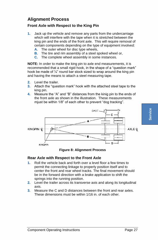
1. Jack up the vehicle and remove any parts from the undercarriage which will interfere with the tape when it is stretched between the king pin and the ends of the front axle. This will require removal of certain components depending on the type of equipment involved: A. The outer wheel for disc type wheels, B. The tire and rim assembly of a steel spoked wheel or, C. The complete wheel assembly in some instances.
NOTE: In order to make the king pin to axle end measurements, it is
recommended that a small rigid hook, in the shape of a “question mark” hook be made of ¼” round bar stock sized to wrap around the king pin and having the means to attach a steel measuring tape.
2. Level the trailer. 3. Attach the “question mark” hook with the attached steel tape to the
king pin. 4. Measure the “A” and “B” distances from the kinig pin to the ends of
the front axle as shown in the illustration. These measurements mjust be within 1/8” of each other to prevent “dog tracking”.
Figure 8: Alignment Process
Rear Axle with Respect to the Front Axle
1. Roll the vehicle back and forth over a level floor a few times to permit the connecting linkage to properly position itself and to center the front and rear wheel tracks. The final movement should be in the forward direction with a brake application to shift the springs into the running position.
2. Level the trailer across its transverse axis and along its longitudinal axis.
3. Measure the C and D distances between the front and rear axles. These dimensions must be within 1/16 in. of each other.
Se
rvic
e
Page 28 Component Operating Instructions
If any of these measurements do not fall within the stated limits, any worn or damaged parts should be replaced before making the necessary change to the length of the adjustable torque arm to bring the axles into alignment. The limits of 1 /16 in. and 1/8 in. may appear small in comparison to the overall dimensions of the trailer, but are recognized as industry standards.
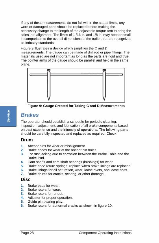
Figure 9 illustrates a device which simplifies the C and D measurements. The gauge can be made of drill rod or pipe fittings. The materials used are not important as long as the parts are rigid and true. The pointer arms of the gauge should be parallel and held in the same plane.
Figure 9: Gauge Created for Taking C and D Measurements
Brakes The operator should establish a schedule for periodic cleaning, inspection, adjustment, and lubrication of all brake components based on past experience and the intensity of operations. The following parts should be carefully inspected and replaced as required. Check:
Drum
1. Anchor pins for wear or misalignment. 2. Brake shoes for wear at the anchor pin holes. 3. For rust jacking due to corrosion between the Brake Table and the
Brake Pad. 4. Cam shafts and cam shaft bearings (bushings) for wear. 5. Brake shoe return springs, replace when brake linings are replaced. 6. Brake linings for oil saturation, wear, loose rivets, and loose bolts. 7. Brake drums for cracks, scoring, or other damage.
Disc
1. Brake pads for wear. 2. Brake rotors for wear. 3. Brake rotors for runout. 4. Adjuster for proper operation. 5. Guide pin bearing play. 6. Brake rotors for abnormal cracks as shown in figure 10.
Se
rvic
e
Component Operating Instructions Page 29
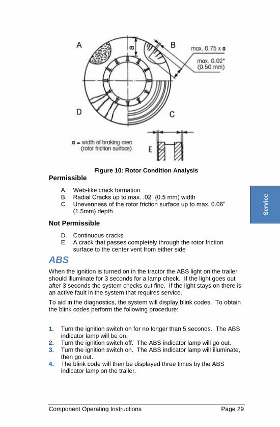
Figure 10: Rotor Condition Analysis
Permissible
A. Web-like crack formation B. Radial Cracks up to max. .02” (0.5 mm) width C. Unevenness of the rotor friction surface up to max. 0.06”
(1.5mm) depth
Not Permissible
D. Continuous cracks E. A crack that passes completely through the rotor friction
surface to the center vent from either side
ABS When the ignition is turned on in the tractor the ABS light on the trailer should illuminate for 3 seconds for a lamp check. If the light goes out after 3 seconds the system checks out fine. If the light stays on there is an active fault in the system that requires service.
To aid in the diagnostics, the system will display blink codes. To obtain the blink codes perform the following procedure:
1. Turn the ignition switch on for no longer than 5 seconds. The ABS indicator lamp will be on.
2. Turn the ignition switch off. The ABS indicator lamp will go out. 3. Turn the ignition switch on. The ABS indicator lamp will illuminate,
then go out. 4. The blink code will then be displayed three times by the ABS
indicator lamp on the trailer.
Se
rvic
e
Page 30 Component Operating Instructions
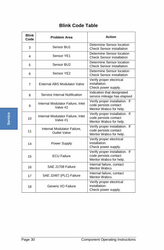
Blink Code Table
Blink Code
Problem Area Action
3 Sensor BU1 Determine Sensor location Check Sensor installation
4 Sensor YE1 Determine Sensor location Check Sensor installation
5 Sensor BU2 Determine Sensor location Check Sensor installation
6 Sensor YE2 Determine Sensor location Check Sensor installation
7 External ABS Modulator Valve
Verify proper electrical installation. Check power supply.
8 Service Interval Notification Indication that designated service mileage has elapsed
9 Internal Modulator Failure, Inlet
Valve #2
Verify proper installation. If code persists contact Meritor Wabco for help.
10 Internal Modulator Failure, Inlet
Valve #1
Verify proper installation. If code persists contact Meritor Wabco for help.
11 Internal Modulator Failure,
Outlet Valve
Verify proper installation. If code persists contact Meritor Wabco for help.
14 Power Supply
Verify proper electrical installation. Check power supply.
15 ECU Failure
Verify proper installation. If code persists contact Meritor Wabco for help.
16 SAE J1708 Failure Internal failure, contact Meritor Wabco.
17 SAE J2497 (PLC) Failure Internal failure, contact Meritor Wabco.
18 Generic I/O Failure
Verify proper electrical installation. Check power supply.
Se
rvic
e
ABS Wheel Speed Sensor Page 31
ABS Wheel Speed Sensor
How to Remove a Sensor
1. Back off the slack adjuster and remove the tire, wheel and drum. 2. Hold the sensor, not the cable, and use a twisting motion to pull the
sensor out of its mounting block. 3. Remove the spring clip from the mounting block. 4. Remove any fasteners that hold the sensor cable to other
components. 5. Disconnect the sensor cable from the extension cable.
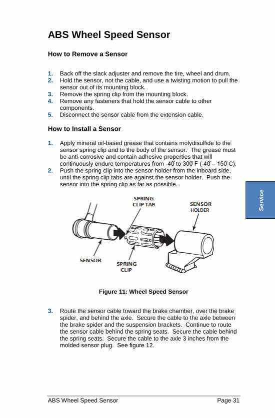
How to Install a Sensor 1. Apply mineral oil-based grease that contains molydisulfide to the
sensor spring clip and to the body of the sensor. The grease must be anti-corrosive and contain adhesive properties that will continuously endure temperatures from -40 ̊to 300̊ F (-40 ̊– 150 ̊C).
2. Push the spring clip into the sensor holder from the inboard side, until the spring clip tabs are against the sensor holder. Push the sensor into the spring clip as far as possible.
Figure 11: Wheel Speed Sensor
3. Route the sensor cable toward the brake chamber, over the brake spider, and behind the axle. Secure the cable to the axle between the brake spider and the suspension brackets. Continue to route the sensor cable behind the spring seats. Secure the cable behind the spring seats. Secure the cable to the axle 3 inches from the molded sensor plug. See figure 12.
Se
rvic
e
Page 32 Wheel Bearings
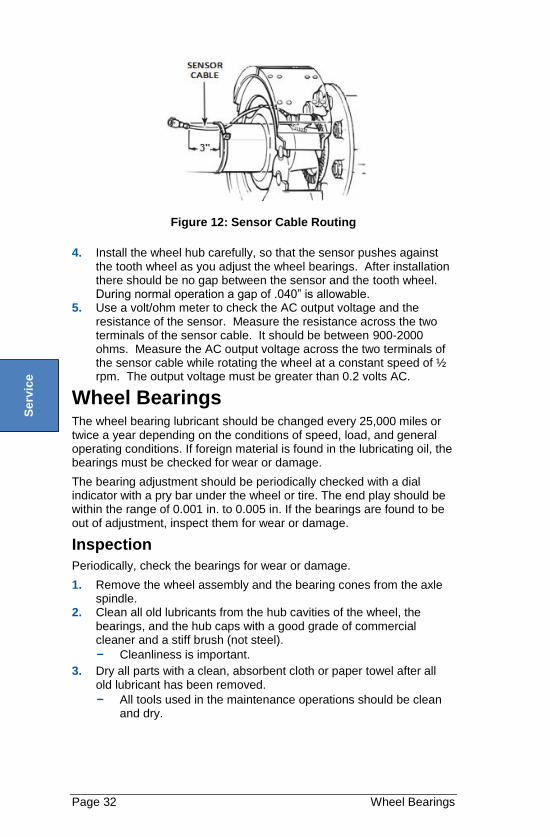
Figure 12: Sensor Cable Routing
4. Install the wheel hub carefully, so that the sensor pushes against the tooth wheel as you adjust the wheel bearings. After installation there should be no gap between the sensor and the tooth wheel. During normal operation a gap of .040” is allowable.
5. Use a volt/ohm meter to check the AC output voltage and the resistance of the sensor. Measure the resistance across the two terminals of the sensor cable. It should be between 900-2000 ohms. Measure the AC output voltage across the two terminals of the sensor cable while rotating the wheel at a constant speed of ½ rpm. The output voltage must be greater than 0.2 volts AC.
Wheel Bearings The wheel bearing lubricant should be changed every 25,000 miles or twice a year depending on the conditions of speed, load, and general operating conditions. If foreign material is found in the lubricating oil, the bearings must be checked for wear or damage.
The bearing adjustment should be periodically checked with a dial indicator with a pry bar under the wheel or tire. The end play should be within the range of 0.001 in. to 0.005 in. If the bearings are found to be out of adjustment, inspect them for wear or damage.
Inspection
Periodically, check the bearings for wear or damage.
1. Remove the wheel assembly and the bearing cones from the axle spindle.
2. Clean all old lubricants from the hub cavities of the wheel, the bearings, and the hub caps with a good grade of commercial cleaner and a stiff brush (not steel).
- Cleanliness is important.
3. Dry all parts with a clean, absorbent cloth or paper towel after all old lubricant has been removed.
- All tools used in the maintenance operations should be clean and dry.
Se
rvic
e
Wheel Bearings Page 33
CAUTION! Do NOT use compressed air in the cleaning operation. This will cause damage to the bearings.
4. Inspect the bearing cups, the bearing cones, and the axle spindles for damage or wear. Should a bearing cone require replacement, the bearing cup should also be replaced for added service life.
5. Reinstall the wheel assembly on the axle following the installation procedures detailed on the following page. Use a new wheel seal and wiper ring as part of the maintenance procedure.
Wheel Hubs and Seals 1. At the time of any maintenance activity, check the hub bore for
burrs and the spindle for any imperfections. 2. Verify that the entire wheel cavity is thoroughly cleaned.
CAUTION! Do NOT use a high pressure wash wand on the hubcaps. This can cause water infiltration and cause damage to the bearings.
3. Apply a thin layer of sealant to the outer diameter of the axle shoulder.
4. Place the seal assembly on the spindle with the words “oil-bearing side” positioned toward the cavity of the hub that will contain the lubricating oil.
5. Place the recommended axle tool over the spindle. 6. Drive the seal assembly onto the spindle until it contacts the face of
the shoulder. 7. Rotate the tool and tap it several times to ensure that the seal is
properly seated. Wipe away all excess sealant. 8. Dip the inner bearing in lubricating oil and place it on the spindle. 9. No additional lubrication is required on the outer diameter of the
wheel seal or in the hub.
- The wheel seals are lubricated at the time of packaging at the factory.
10. With the wheel supported by a wheel dolly, carefully place the wheel onto the axle spindle until it contacts the seal.
11. Dip the outer wheel bearing in lubricating oil and place it onto the spindle and into the bearing cup.
12. Assemble the inner nut according to the manufacturer’s instructions. If the nut is an axilok brand follow instructions below: A. Put axilok in the correct size six-point socket and verify that the
locking clips are compressed (figure 13). Retainer clips should spin freely.
Se
rvic
e
Page 34 Wheel Bearings
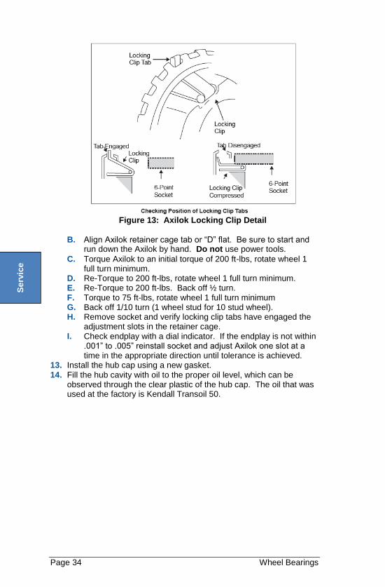
Figure 13: Axilok Locking Clip Detail
B. Align Axilok retainer cage tab or “D” flat. Be sure to start and run down the Axilok by hand. Do not use power tools.
C. Torque Axilok to an initial torque of 200 ft-lbs, rotate wheel 1 full turn minimum.
D. Re-Torque to 200 ft-lbs, rotate wheel 1 full turn minimum. E. Re-Torque to 200 ft-lbs. Back off ½ turn. F. Torque to 75 ft-lbs, rotate wheel 1 full turn minimum G. Back off 1/10 turn (1 wheel stud for 10 stud wheel). H. Remove socket and verify locking clip tabs have engaged the
adjustment slots in the retainer cage. I. Check endplay with a dial indicator. If the endplay is not within
.001” to .005” reinstall socket and adjust Axilok one slot at a time in the appropriate direction until tolerance is achieved.
13. Install the hub cap using a new gasket. 14. Fill the hub cavity with oil to the proper oil level, which can be
observed through the clear plastic of the hub cap. The oil that was used at the factory is Kendall Transoil 50.
Se
rvic
e
Troubleshooting Page 35
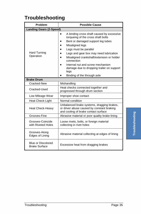
Troubleshooting
Problem Possible Cause
Landing Gears (2-Speed)
Hard Turning Operation
A binding cross shaft caused by excessive torqueing of the cross shaft bolts
Bent or damaged support leg tubes
Misaligned legs
Legs must be parallel
Legs and gear box may need lubrication
Misaligned crankshaft/extension or holder connection
Internal nut and screw mechanism damage due to dropping trailer on support legs
Binding of the through axle
Brake Drum
Cracked-New Mishandling
Cracked-Used Heat checks connected together and progressed through drum section
Low Mileage Wear Improper shoe contact
Heat Check-Light Normal condition
Heat Check-Heavy Unbalanced brake systems, dragging brakes, or driver abuse caused by constant braking and cooling of brake contact surface
Grooves-Fine Abrasive material or poor quality brake lining
Grooves-Coincide with Riveted Holes
Loose rivets, bolts, or foreign material collecting in rivet holes
Grooves-Along Edges of Lining
Abrasive material collecting at edges of lining
Blue or Discolored Brake Surface
Excessive heat from dragging brakes
Tro
ub
les
ho
oti
ng
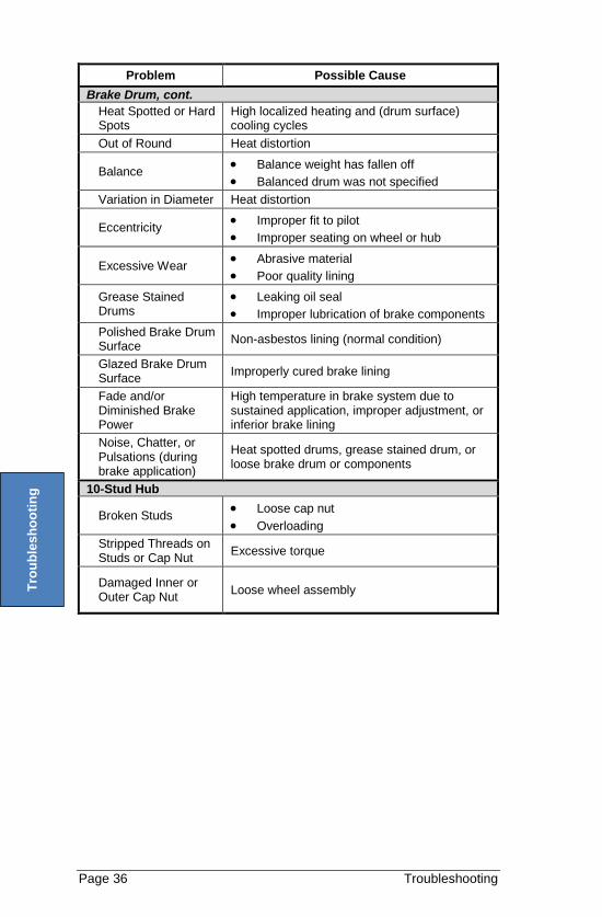
Page 36 Troubleshooting
Problem Possible Cause
Brake Drum, cont.
Heat Spotted or Hard Spots
High localized heating and (drum surface) cooling cycles
Out of Round Heat distortion
Balance Balance weight has fallen off
Balanced drum was not specified
Variation in Diameter Heat distortion
Eccentricity Improper fit to pilot
Improper seating on wheel or hub
Excessive Wear Abrasive material
Poor quality lining
Grease Stained Drums
Leaking oil seal
Improper lubrication of brake components
Polished Brake Drum Surface
Non-asbestos lining (normal condition)
Glazed Brake Drum Surface
Improperly cured brake lining
Fade and/or Diminished Brake Power
High temperature in brake system due to sustained application, improper adjustment, or inferior brake lining
Noise, Chatter, or Pulsations (during brake application)
Heat spotted drums, grease stained drum, or loose brake drum or components
10-Stud Hub
Broken Studs Loose cap nut
Overloading
Stripped Threads on Studs or Cap Nut
Excessive torque
Damaged Inner or Outer Cap Nut
Loose wheel assembly
Tro
ub
les
ho
oti
ng
Electrical Page 37
SCHEMATICS
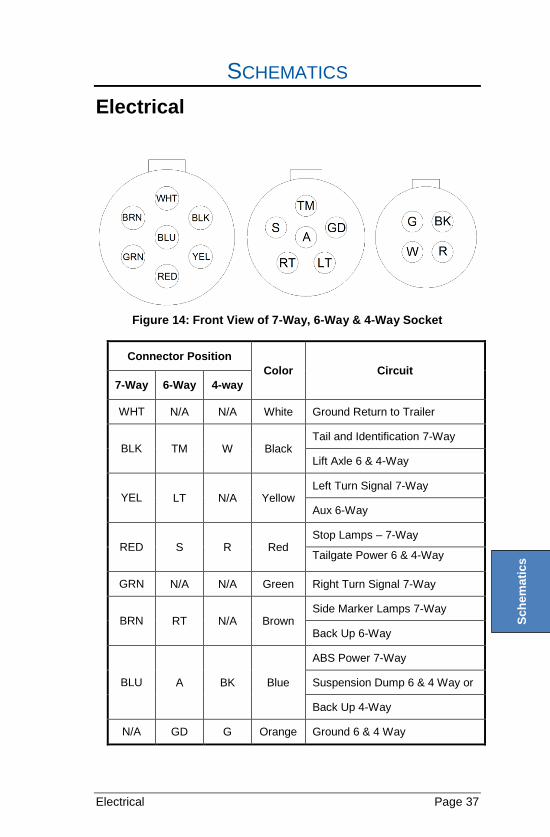
Electrical
Figure 14: Front View of 7-Way, 6-Way & 4-Way Socket
Connector Position
Color Circuit
7-Way 6-Way 4-way
WHT N/A N/A White Ground Return to Trailer
BLK TM W Black Tail and Identification 7-Way
Lift Axle 6 & 4-Way
YEL LT N/A Yellow Left Turn Signal 7-Way
Aux 6-Way
RED S R Red Stop Lamps – 7-Way
Tailgate Power 6 & 4-Way
GRN N/A N/A Green Right Turn Signal 7-Way
BRN RT N/A Brown Side Marker Lamps 7-Way
Back Up 6-Way
BLU A BK Blue
ABS Power 7-Way
Suspension Dump 6 & 4 Way or
Back Up 4-Way
N/A GD G Orange Ground 6 & 4 Way
Sc
he
ma
tic
s
Page 38 Electrical
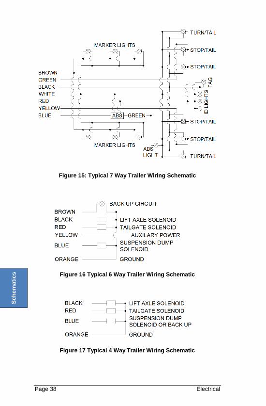
Figure 15: Typical 7 Way Trailer Wiring Schematic
Figure 16 Typical 6 Way Trailer Wiring Schematic
Figure 17 Typical 4 Way Trailer Wiring Schematic
Sc
he
ma
tic
s
Electrical Page 39
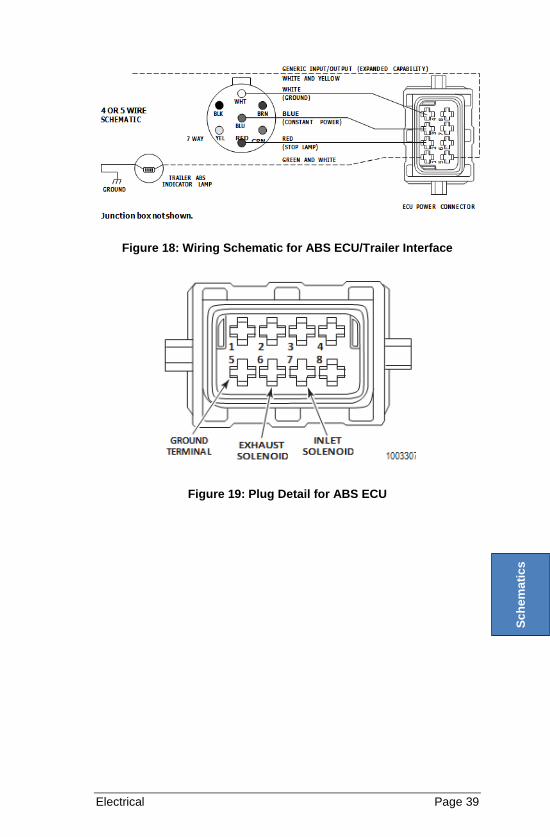
Figure 18: Wiring Schematic for ABS ECU/Trailer Interface
Figure 19: Plug Detail for ABS ECU
S
ch
em
ati
cs
Page 40 NHTSA Information
NHTSA INFORMATION
If you believe that your vehicle has a defect which could cause a crash or could cause injury or death, you should immediately inform the National Highway Traffic Safety Administration (NHTSA), in addition to notifying East Manufacturing Corporation.
If NHTSA receives similar complaints, it may open an investigation, and if it finds that a safety defect exists in a group of vehicles, it may order a recall and remedy campaign. However, NHTSA cannot become involved in individual problems between you, your dealer, or East Manufacturing Corporation.
To contact NHTSA, you may either call the Auto Safety Hotline toll-free at 1-800-424-9393 (or 366-0123 in Washington, D.C. area) or write to:
NHTSA U.S. Department of Transportation 1200 New Jersey Ave, SE Washington, D.C. 20590
You can also obtain other information about motor vehicle safety from www.nhtsa.gov and the Auto Safety Hotline.

NOTES

NOTES
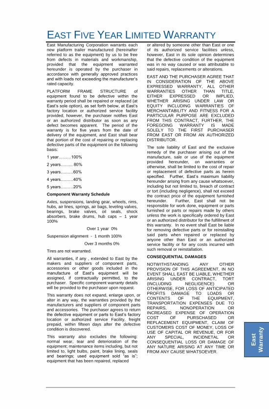
EAST FIVE YEAR LIMITED WARRANTY East Manufacturing Corporation warrants each new platform trailer manufactured (hereinafter referred to as the equipment) by us to be free from defects in materials and workmanship, provided that the equipment warranted hereunder is operated by the purchaser in accordance with generally approved practices and with loads not exceeding the manufacturer’s rated capacity.
PLATFORM FRAME STRUCTURE of equipment found to be defective within the warranty period shall be repaired or replaced (at East’s sole option), as set forth below, at East’s factory location or authorized service facility provided, however, the purchaser notifies East or an authorized distributor as soon as any defect becomes apparent. The period of the warranty is for five years from the date of delivery of the equipment, and East shall bear that portion of the cost of repairing or replacing defective parts of the equipment on the following basis:
1 year………100%
2 years……... 80%
3 years………60%
4 years………40%
5 years………20%
Component Warranty Schedule
Axles, suspensions, landing gear, wheels, rims, hubs, air lines, springs, air bags, leveling valves, bearings, brake valves, oil seals, shock absorbers, brake drums, hub caps – 1 year 100%
Over 1 year 0%
Suspension alignment - 1 month 100%
Over 3 months 0%
Tires are not warranted.
All warranties, if any , extended to East by the makers and suppliers of component parts, accessories or other goods included in the manufacture of East’s equipment will be assigned, if contractually permitted, to the purchaser. Specific component warranty details will be provided to the purchaser upon request.
This warranty does not expand, enlarge upon, or alter in any way, the warranties provided by the manufacturers and suppliers of component parts and accessories. The purchaser agrees to return the defective equipment or parts to East’s factory location or authorized service Facility, freight prepaid, within fifteen days after the defective condition is discovered.
This warranty also excludes the following: normal wear, tear and deterioration of the equipment; maintenance items including, but not limited to, light bulbs, paint, brake lining, seals and bearings; used equipment sold “as is”; equipment that has been repaired, replaced
or altered by someone other than East or one of its authorized service facilities unless, however, East in its sole opinion determines that the defective condition of the equipment was in no way caused or was attributable to said repairs, replacements or alterations.
EAST AND THE PURCHASER AGREE THAT IN CONSIDERATION OF THE ABOVE EXPRESSED WARRANTY, ALL OTHER WARRANTIES OTHER THAN TITLE, EITHER EXPRESSED OR IMPLIED, WHETHER ARISING UNDER LAW OR EQUITY INCLUDING WARRANTIES OF MERCHANTABILITY AND FITNESS FOR A PARTICULAR PURPOSE ARE EXCLUDED FROM THIS CONTRACT, FURTHER, THE FOREGOING WARRANTY IS MADE SOLELY TO THE FIRST PURCHASER FROM EAST OR FROM AN AUTHORIZED DISTRIBUTOR.
The sole liability of East and the exclusive remedy of the purchaser arising out of the manufacture, sale or use of the equipment provided hereunder, on warranties or otherwise, shall be limited to the cost of repair or replacement of defective parts as herein specified. Further, East’s maximum liability hereunder arising from any cause whatsoever, including but not limited to, breach of contract or tort (including negligence), shall not exceed the contract price of the equipment furnished hereunder. Further, East shall not be responsible for work done, equipment or parts furnished or parts or repairs made by others unless the work is specifically ordered by East or an authorized distributor for the fulfillment of this warranty. In no event shall East be liable for removing defective parts or for reinstalling said parts when repaired or replaced by anyone other than East or an authorized service facility or for any costs incurred with such removal or reinstallation.
CONSEQUENTIAL DAMAGES
NOTWITHSTANDING ANY OTHER PROVISION OF THIS AGREEMENT, IN NO EVENT SHALL EAST BE LIABLE, WHETHER ARISING UNDER CONTRACT, TORT (INCLUDING NEGLIGENCE) OR OTHERWISE, FOR LOSS OF ANTICIPATED PROFITS DAMAGE TO LOADS OR CONTENTS OF THE EQUIPMENT, TRANSPORTATION EXPENSES DUE TO REPAIRS, NONOPERATION OR INCREASED EXPENSE OF OPERATION COST OF PURSCHASED OR REPLACEMENT EQUIPMENT, CLAIM OF CUSTOMERS COST OF MONEY, LOSS OF USE OF CAPITAL OR REVENUE, OR FOR ANY SPECIAL, INCIDNETAL OR CONSEQUENTIAL LOSS OR DAMAGE OF ANY NATURE ARISING AT ANY TIME OR FROM ANY CAUSE WHATSOEVER.
Ea
st
Wa
rra
nty
East Manufacturing Corporation
1871 State Route 44 Randolph, OH 44265
www.eastmfg.com
Local: (330) 325-9921
Fax: (330) 325-7851
Sales: (888) 405-3278
Parts: (800) 362-0851
Warranty: (330) 325-9921
Service: (330) 325-9921
Recommended