Instructions for Use
ELx808™ Absorbance Microplate Reader
September 2012 © 2012 Part Number 7341029 Revision C BioTek® Instruments, Inc.

ii | Preface
Notices
BioTek® Instruments, Inc.
P.O. Box 998, Highland Park
Winooski, Vermont 05404-0998 USA
All Rights Reserved
© 2012, BioTek® Instruments, Incorporated. No part of this publication may be reproduced, transcribed, or transmitted in any form, or by any means electronic or mechanical, including photocopying and recording, for any purpose other than the purchaser’s use without written permission of BioTek Instruments, Inc.
Trademarks
BioTek® is a registered trademark, and ELx808™, and Gen5™ are trademarks of BioTek Instruments, Inc. Microsoft®, Windows®, and Excel® are either registered trademarks or trademarks of Microsoft Corporation in the United States and/or other countries.
Adobe® Acrobat® is either a registered trademark or trademark of Adobe Systems, Incorporated in the United States and/or other countries.
All other trademarks are the property of their respective holders.
Restrictions and Liabilities
Information in this document is subject to change and does not represent a commitment by BioTek Instruments, Inc. Changes made to the information in this document will be incorporated in new editions of the publication. BioTek assumes no responsibility for the use or reliability of software or equipment that is not supplied by BioTek or its affiliated dealers.
BioTek Instruments, Inc.

Contact Information | iii
Contact Information
BioTek® Instruments, Inc.
P.O. Box 998, Highland Park
Winooski, Vermont 05404-0998 USA
Customer Service and Sales
Internet: www.biotek.com
Phone: 888-451-5171 (toll free in the U.S.)
802-655-4740 (outside the U.S.)
Fax: 802-655-7941
E-Mail: [email protected]
Service/TAC
Phone: 800-242-4685 (toll free in the U.S.)
802-655-4740 (outside the U.S.)
Fax: 802-654-0638
E-Mail: [email protected]
European Coordination Center/Authorized European Representative
BioTek® Instruments GmbH
Kocherwaldstrasse 34
D-74177 Bad Friedrichshall
Germany
Internet: www.biotek.de
Phone: +49 (0) 7136 9680
Fax: +49 (0) 7136 968 111
E-Mail: [email protected]
ELx808 Instructions for Use

iv | Preface
Instructions for Use Requirements
This document fulfills the basic needs of persons operating this device, according to the requirements of the In Vitro Diagnostic Directive for “Instructions for Use.” Many of the device’s higher-level functions, such as programming and advanced troubleshooting, are described in the Operator’s Manual.
Intended Use Statement
• The ELx808 is an absorbance microplate reader. The performance characteristics of the data reduction software have not been established with any laboratory diagnostic assay. The user must evaluate this instrument and (if used) PC-based software in conjunction with their specific assay(s). This evaluation must include the confirmation that performance characteristics for the specific assay(s) are met.
• If the instrument has an “IVD” label, it may be used for clinical and non-clinical purposes, including research and development. If there is no such label, the instrument may be used only for research and development or other non-clinical purposes.
Quality Control
It is considered good laboratory practice to run laboratory samples according to instructions and specific recommendations included in the package insert or standard laboratory protocol for the test to be conducted. Failure to conduct Quality Control checks could result in erroneous test data.
Warranty and Product Registration
Take a moment to review the Warranty information that shipped with your product. Please also register your product with BioTek to ensure that you receive important information and updates about the product(s) you have purchased.
You can register online through the Customer Resource Center (CRC) at www.biotek.com or by calling 888-451-5171 or 802-655-4740.
BioTek Instruments, Inc.

Repackaging and Shipping | v
Repackaging and Shipping
If you need to ship the instrument to BioTek for service or repair, contact BioTek for a Return Materials Authorization (RMA) number, and be sure to use the original packing materials. Other forms of commercially available packaging are not recommended and can void the warranty. If the original packing materials have been damaged or lost, contact BioTek for replacement packing.
Warnings
Operate the instrument on a level surface and away from excessive humidity.
Bright sunlight or strong incandescent light can reduce the linear performance range of the instrument.
Measurement values may be affected by extraneous particles (such as dust) in the microplate wells. A clean work area is necessary to ensure accurate readings.
When operated in a safe environment according to the instructions in this document, there are no known hazards associated with the ELx808. However, the operator should be aware of certain situations that could result in serious injury; these may vary depending on the instrument model. See Hazards and Precautions.
Hazards
The following hazard warnings are provided to help avoid injury:
Warning! Power Rating. The ELx808 or its power supply must be connected to a power receptacle that provides voltage and current within the specified rating for the system. Use of an incompatible power receptacle may produce electrical shock and fire hazards.
Warning! Electrical Grounding. Never use a plug adapter to connect primary power to the ELx808 or to the external power supply. Use of an adapter disconnects the utility ground, creating a severe shock hazard. Always connect the power cord directly to an appropriate receptacle with a functional ground.
ELx808 Instructions for Use

vi | Preface
Warning! Internal Voltage. Always turn off the power switch and unplug the power cord or power supply before cleaning the outer surface of the instrument or removing its top case.
Warning! Service. Only qualified technical personnel should perform service procedures on internal components.
Warning! Accessories. Only accessories that meet the manufacturer’s specifications shall be used with the instrument.
Warning! Liquids. Avoid spilling liquids on the reader; fluid seepage into internal components creates a potential for shock hazard or instrument damage. If a spill occurs while a program is running, abort the program and turn the instrument off. Wipe up all spills immediately. Do not operate the instrument if internal components have been exposed to fluid.
Warning! Software Quality Control. The operator must follow the manufacturer’s assay package insert when modifying software parameters and establishing read methods. Failure to conduct quality control checks could result in erroneous test data.
Warning! Unspecified Use. Failure to operate this equipment according to the guidelines and safeguards specified in this manual could result in a hazardous condition.
Warning! Hot Surface. The lamp assembly is hot when the instrument is turned on. Turn off the reader and allow the lamp to cool down before attempting to replace it.
Warning! Reader Data Reduction Protocol. For readers with onboard assay software, the software will flag properly defined controls when they are out of range. The software will present the data with the appropriate error flags for the operator to determine control and assay validation. For readers operated via computer control, no limits are applied to the raw absorbance data. All information exported via computer control must be thoroughly analyzed by the operator.
Warning! Potential Biohazards. Some assays or specimens may pose a biohazard. Adequate safety precautions should be taken as outlined in the assay’s package insert. Always wear safety glasses and appropriate protective equipment, such as chemically resistant rubber gloves and apron.
BioTek Instruments, Inc.

Precautions | vii
Precautions
The following precautions are provided to help avoid damage to the instrument:
Caution: Service. The instrument should be serviced by BioTek authorized service personnel. Only qualified technical personnel should perform troubleshooting and service procedures on internal components.
Caution: Spare Parts. Only approved spare parts should be used for maintenance. The use of unapproved spare parts and accessories may result in a loss of warranty and potentially impair instrument performance or cause damage to the instrument.
Caution: Environmental Conditions. Do not expose the instrument to temperature extremes. For proper operation, ambient temperatures should remain within the range listed in the Specifications section. Performance may be adversely affected if temperatures fluctuate above or below this range. Storage temperature limits are broader (see the Operator’s Manual).
Caution: Sodium Hypochlorite. Do not expose any part of the instrument to the recommended diluted sodium hypochlorite solution (bleach) for more than 20 minutes. Prolonged contact may damage the instrument surfaces. Be certain to rinse and thoroughly wipe all surfaces.
Caution: Warranty. Failure to follow preventive maintenance protocols may void the warranty. See the Operator’s Manual.
Caution: External Power Supply. (For ELx808 readers manufactured after December 2005.) Only use the power supply shipped with the instrument. Operate this power supply within the range of line voltages listed on it.
Caution: Disposal. This instrument contains printed circuit boards and wiring with lead solder. Dispose of the instrument according to Directive 2002/96/EC, “on waste electrical and electronic equipment (WEEE)” or local ordinances.
Caution: Electromagnetic Environment. Per EN 61326-2-6 it is the user’s responsibility to ensure that a compatible electromagnetic environment for this instrument is provided and maintained in order that the device will perform as intended.
Caution: Electromagnetic Compatibility. Do not use this device in close proximity to sources of strong electromagnetic radiation (e.g., unshielded intentional RF sources), as these may interfere with the proper orientation.
ELx808 Instructions for Use

viii | Preface
CE Mark
Based on the testing described below and information contained herein, this instrument bears the CE mark
Directive 2004/108/EC: Electromagnetic Compatibility
Emissions - Class A
The system has been type-tested by an independent, accredited testing laboratory and found to meet the requirements of EN 61326-1: Class A for Radiated Emissions and Line Conducted Emissions. Verification of compliance was conducted to the limits and methods of EN 55011—CISPR 11, Class A. In a domestic environment it may cause radio interference, in which case you may need to mitigate the interference.
Immunity
The system has been type-tested by an independent, accredited testing laboratory and found to meet the requirements of EN 61326-1 and EN 61326-2-6 for Immunity. Verification of compliance was conducted to the limits and methods of the following:
EN 61000-4-2 Electrostatic Discharge
EN 61000-4-3 Radiated EM Fields
EN 61000-4-4 Electrical Fast Transient/Burst
EN 61000-4-5 Surge Immunity
EN 61000-4-6 Conducted Disturbances from RFI
EN 61000-4-11 Voltage Dips, Short Interruptions and Variations
Directive 2006/95/EC: Low Voltage (Safety)
The system has been type-tested by an independent testing laboratory and was found to meet the requirements of this Directive. Verification of compliance was conducted to the limits and methods of the following:
EN 61010-1, “Safety requirement for electrical equipment for measurement, control and laboratory use. Part 1, General requirements.”
Directive 2002/96/EC: Waste Electrical and Electronic Equipment
Disposal Notice: This instrument contains printed circuit boards and wiring with lead solder. Dispose of the instrument according to Directive 2002/96/EC, “on waste electrical and electronic equipment (WEEE)” or local ordinances.
BioTek Instruments, Inc.

CE Mark | ix
Directive 98/79/EC: In Vitro Diagnostics (if labeled for this use)
• Product registration with competent authorities • Traceability to the U.S. National Institute of Standards and Technology (NIST):
ELx808 Instructions for Use

x | Preface
Safety Symbols
Some of these symbols may appear on the instrument or accessories:
Alternating current Courant alternatif Wechselstrom Corriente alterna Corrente alternata
Both direct and alternating current Courant continu et courant alternatif Gleich - und Wechselstrom Corriente continua y corriente alterna Corrente continua e corrente alternata
Direct current Courant continu Gleichstrom Corriente continua Corrente continua
Earth ground terminal Borne de terre Erde (Betriebserde) Borne de tierra Terra (di funzionamento)
On (Supply) Marche (alimentation) Ein (Verbindung mit dem Netz) Conectado Chiuso
Protective conductor terminal Borne de terre de protection Schutzleiteranschluss Borne de tierra de protección Terra di protezione
Off (Supply) Arrêt (alimentation) Aus (Trennung vom Netz) Desconectado Aperto (sconnessione dalla rete di alimentazione)
Caution (refer to accompanying documents) Attention (voir documents d’accompanement) Achtung siehe Begleitpapiere Atención (vease los documentos incluidos) Attenzione, consultare la doc annessa
Warning, risk of electric shock Attention, risque de choc électrique Gefährliche elektrische schlag Precaución, riesgo de sacudida eléctrica Attenzione, rischio di scossa elettrica
Warning, risk of crushing or pinching Attention, risque d’écrasement et pincement Warnen, Gefahr des Zerquetschens und Klemmen Precaución, riesgo del machacamiento y sejeción Attenzione, rischio di schiacciare ed intrappolarsi
Warning, hot surface Attention, surface chaude Warnen, heiße Oberfläche Precaución, superficie caliente Attenzione, superficie calda
Warning, potential biohazards Attention, risques biologiques potentiels Warnung! Moegliche biologische Giftstoffe Atención, riesgos biológicos Attenzione, rischio biologico
BioTek Instruments, Inc.

Safety Symbols | xi
In vitro diagnostic medical device Dispositif médical de diagnostic in vitro Medizinisches In-Vitro-Diagnostikum Dispositivo médico de diagnóstico in vitro Dispositivo medico diagnostico in vitro
Separate collection for electrical and electronic equipment Les équipements électriques et électroniques font l’objet d’une collecte sélective Getrennte Sammlung von Elektro- und Elektronikgeräten Recogida selectiva de aparatos eléctricos y electrónicos Raccolta separata delle apparecchiature elettriche ed elettroniche
Consult instructions for use Consulter la notice d’emploi Gebrauchsanweisung beachten Consultar las instrucciones de uso Consultare le istruzioni per uso
ELx808 Instructions for Use

xii | Preface
BioTek Instruments, Inc.

Installation

2 | Installation
BioTek® Instruments, Inc.
Package Contents
• ELx808 Absorbance Microplate Reader
• Power cord (PN varies according to country of use)
• Power supply for readers manufactured after December 2005 (PN 01281)
• Filter wheel with four standard filters: 405 nm, 450 nm, 490 nm, 630 nm, and two blank filters. The ELx808IU includes a 340 nm filter.
• Operator’s Manual (PN 7341000)
• Dust cover (PN 7342066)
• Serial cable (PN 75053)
Part numbers are subject to change. Please contact BioTek Customer Care if you have any questions.

1: Unpack and Inspect the Instrument | 3
ELx808 Instructions for Use
1: Unpack and Inspect the Instrument
Important! Save all packaging materials. If you need to ship the reader to BioTek for service or repair, you must use the original packing. Other forms of commercially available packing are not recommended and can void the warranty.
If the original packaging materials have been damaged or lost, contact BioTek and ask for PN 7343000. See Product Support & Service in Chapter 1 of the Operator’s Manual for contact information.
The instrument’s packaging design is subject to change. If the instructions in this section do not appear to apply to the packaging materials you are using, please contact BioTek’s Technical Assistance Center for guidance.
The ELx808 and its accessories are securely packaged inside custom-designed shipping materials. This packaging should protect the instrument from damage during shipping. Inspect the shipping box, packaging, instrument, and accessories for signs of damage.
If the shipping box has been damaged: Inspect the instrument for visible dents and scratches as you unpack it.
If the reader is damaged: Notify the carrier and your BioTek sales representative. BioTek will arrange for repair or replacement of your reader immediately.
1. Carefully open the top of the box, and remove any accessories. These include a power cord, a filter wheel in a padded envelope, and an Operator’s Manual.
2. Remove the end caps from the reader.
3. Lift the reader out of the box, and place it on a level surface. Remove the reader from the plastic bag.
4. Remove the filter wheel from the shipping envelope.
5. Place all packing material back into the shipping box for reuse if the instrument needs to be shipped again.

4 | Installation
BioTek® Instruments, Inc.
Figure 1

2: Select the Operating Environment | 5
ELx808 Instructions for Use
2: Select the Operating Environment
For best operation, install the ELx808 on a level surface in an area where ambient temperatures between 18°C (64°F) and 40°C (104°F) can be maintained.
The reader is sensitive to extreme environmental conditions. Conditions to avoid are:
• Excessive humidity: Condensation directly on the sensitive electronic circuits can cause the instrument to fail internal self-checks. The humidity must be in the range of 10% to 85%, noncondensing.
• Excessive ambient light: Bright sunlight or strong incandescent light can reduce the linear performance range and affect the instrument’s readings.
• Dust: Optical density readings may be affected by extraneous particles (such as dust) in the microplate wells. A clean work area is necessary to ensure accurate readings.
3: Install the Filter Wheel
The filter wheel must be installed before the reader is used (refer to Figure 2 on the next page):
1. If the reader is on, turn it off and disconnect power.
2. Remove the seven screws around the perimeter of the shroud with a screwdriver.
Tip: Bring the reader to the edge of the work surface to access the screws without having to turn the reader upside down.
3. Carefully lift up the shroud from the front. Hold or tape the plate access door closed as the shroud is being lifted.
4. Ensure that all locations on the filter wheel contain either a filter or a blank. Each location on the filter wheel must be occupied for the reader to operate properly. Take a moment to record the filter values in each location (e.g., 405 nm in position 1).
Important! Keep track of all filter locations. The physical location of the filters must match the filter locations mapped in the reader’s software filter table. The filter wheel must have no empty locations; all locations must be filled with either a filter or a blank plug. Install all filters with the arrow denoting the light direction pointing downward.

6 | Installation
BioTek® Instruments, Inc.
5. The filter wheel hub is located in the rear left corner inside the reader. The wheel is held onto the hub by a magnet. To install the filter wheel:
• Ensure that all locations on the wheel contain either a filter or a blank.
• Write down the filter wheel positions and their contents (e.g., Position 1 = 405 nm filter).
• Align the notch on the hub with the peg on the wheel.
• Apply firm pressure to attach the wheel to the hub. Engage the peg in the notch for proper installation.
• Ensure that the wheel is flat against the hub and rotates freely.
• Lower the top shroud back into position and remove tape if used to steady the plate access door.
• Reinstall the seven screws removed from the perimeter of the shroud.
Important! Be sure to replace the seven perimeter screws.These screws increase the reader’s ability to withstand electrostatic discharges and electromagnetic interference. The screws also hold the shroud in place when shipping the instrument back to BioTek.

3: Install the Filter Wheel | 7
ELx808 Instructions for Use
Figure 2

8 | Installation
BioTek® Instruments, Inc.
4: Adjust the Line Input Voltage Range
For ELx808 readers manufactured before December 2005 only: The reader is powered by an internal, adjustable four-voltage range power input module, instead of by the external power supply. For instructions for checking or adjusting the power input voltage setting, and for reconfiguring or replacing the fuses, refer to the Operator’s Manual.
5: Connect Power
ELx808 with the External Power Supply:
1. Connect the power cord to the external power supply.
2. Locate the power inlet on the right side of the reader.
3. Plug the rounded end of the power supply’s line cord into the power inlet.
4. Plug the other end of the power cord into an appropriate power receptacle.
ELx808 with the Internal Power Input Module:
1. Locate the power inlet on the right side of the reader.
2. Plug the rounded end of the power cord into the power inlet.
3. Plug the other end of the cord into an appropriate power receptacle.
Warning! Power Rating. The ELx808 or power supply must be connected to a power receptacle that provides voltage and current within the specified rating for the system. Use of an incompatible power receptacle may produce electrical shock and fire hazards.
Warning! Electrical Grounding. Never use a plug adapter to connect primary power to the ELx800 power supply. Use of an adapter disconnects the utility ground, creating a severe shock hazard. Always connect the power supply cord directly to an appropriate receptacle with a functional ground.

6: (Optional) Connect Printer | 9
ELx808 Instructions for Use
6: (Optional) Connect Printer
If the ELx808 will be operated in standalone mode (that is, without BioTek’s Gen5 software running on a host computer), connect a printer directly to the reader using the supplied parallel cable.
1. Important! If the reader and/or printer are on, turn them off.
2. Place the printer in a location adjacent to the reader.
3. Attach one end of the parallel cable to the printer’s parallel port.
4. Attach the other end of the cable to the reader’s parallel port on the instrument’s rear panel.
5. Tighten the securing screws on both ends of the cable.
6. Turn on the printer.
Figure 3

10 | Installation
BioTek® Instruments, Inc.
7: Turn on the Reader and Run a System Test
Locate the reader’s power switch (on the right side) and turn on the reader. The ELx808 will automatically perform a System Test.
• If the test passes, the reader will beep once and the display will show the software’s main menu, which will resemble one of the following:
Main Menu screen – ELx808
R E A D Y 0 1 : 3 0 P M 1 0 / 0 9 / 1 0
R E A D D E F I N E R E P O R T U T I L
Main Menu screen – ELx808IU
R E A D Y 0 1 : 3 0 P M 3 7 . 0 º C
R E A D D E F I N E R E P O R T U T I L
• If the test fails, the reader will beep repeatedly and the display will show an error code. If this happens, write down the error code and then press the STOP key on the keypad to stop the beep. Look up the error code in the Operator’s Manual to determine its cause.
8: Adjust the Reader’s Filter Table Setting
Select UTIL > SETUP > FILTER to view/change the reader’s internal filter table. It must exactly match the contents of the filter wheel. See the Operator’s Manual for more information.
Where to Go From Here
Refer to the Operator’s Manual for instructions for the following, as applicable:
• Configuring Utility Options
• Connecting a host computer and installing software
• Verifying performance after installation and setup
• Recommendations for achieving optimum performance
• Repackaging the instrument

Getting Started

12 | Getting Started
Introduction
This section discusses the basic operation of the ELx808 through its front panel (2-line display and keypad). The reader can also be controlled by BioTek’s Gen5 software running on an external computer. For more detailed information on operating the ELx808 via the keypad or other software, refer to the Operator’s Manual.
Figure 4
BioTek Instruments, Inc.

Introduction | 13
Keypad Description
Use the four “soft keys,” located directly below the display, to select options presented on the display.
Exit the current screen and return to the Main Menu.
To scroll through the available options within a screen, press Options or Shift + Options. Press ENTER to select the current option.
Save the current screen settings and advance to the next screen in a series.
Move to a previous menu.
Delete an entry.
Move the cursor to the left in the display.
Move the cursor to the right in the display.
Initiate a plate read.
Stop (abort) a read in progress.
Main Menu
Options
ENTER
Previous Screen
CLEAR
◄
►
READ
STOP
ELx808 Instructions for Use

14 | Getting Started
The Startup Screen
To turn on the ELx808, press the power switch on the right side of the reader’s base. The ELx808 will perform a system self-test, displaying the screens shown below until initialization is complete. During this time, all keys are inactive.
If the self-test fails, the reader will “beep” and display an error code. Press STOP to stop the beep. Refer to the Operator’s Manual to interpret this code. Contact BioTek’s Technical Assistance Center for further assistance with troubleshooting.
P O W E R U P S E Q U E N C E V X . X X
I N I T I A L I Z I N G . . .
B I O T E K E L X 8 0 8
S E L F - T E S T . . . . .
The Main Menu Screen
Following successful power-up of the ELx808, the Main Menu screen appears. This screen varies slightly depending on the reader model:
R E A D Y 0 1 : 3 0 P M 1 0 / 0 9 / 0 7
R E A D D E F I N E R E P O R T U T I L
(ELx808 model)
R E A D Y 0 1 : 3 0 P M 3 7 . 0 º C
R E A D D E F I N E R E P O R T U T I L
(ELx808IU model with incubation/UV capability)
(ELx808IU) The temperature is the actual averaged temperature of the incubator’s four zones. The applied setpoint of the last assay run is used. To vary the temperature, a new setpoint value must be assigned to an assay before running.
BioTek Instruments, Inc.

Introduction | 15
The main menu permits access to all reader functions:
• READ: Choose a pre-defined assay for plate reading. Alternatively, press the key labeled READ on the keypad.
• DEFINE: Create a reading and data reduction protocol. You will be prompted to select/edit an assay and then define its various parameters.
• REPORT: Print results reports and assay descriptions. For results reports, you will be prompted to select a previously run assay containing valid data.
• UTIL: Access various onboard utilities, used for configuring and testing the reader.
Quick Read
On some readers, Assay 01 has been designed to allow for quick and simple assay programming. It appears as _Quick Read on the display. Most of the options available in Assays 2 through 55, and described in this section, are unavailable for programming within Quick Read. You can access the Quick Read assay when READ is selected from the main menu.
The Quick Read assay DEFINE settings are shown below, and cannot be edited, except where noted:
METHOD
• Single Wavelength 405 nm (editable)
MAP
• 96-well plate geometry
• Blank on Air
• Automap
• Map starting location A1
• Samples only (no blanks, standard, or controls)
• Sample count prompted at runtime (can be turned off in UTIL > READ options)
ELx808 Instructions for Use

16 | Getting Started
Defining Assays
The “Instructions for Programming a New Assay” section in the Operator’s Manual provides two examples of assay kit instructions and step-by-step directions for programming each assay. The appendix includes two sample assays: one with a ratio transformation calculation and a POS/NEG cutoff determination, and another with a standard curve.
The Main Menu option DEFINE allows you to customize previously-defined assays stored in the reader’s memory.
1. Start at the Main Menu and select DEFINE. The Select Assay Number screen appears:
S E L E C T A S S A Y N U M B E R : 0 1
N A M E : H B S - A G 1
2. Select an assay to customize and press Enter. The edit assay Name screen
appears:
N A M E : H B S - A G 1
- / : S P A C E
3. Edit the assay name (optional) and press Enter. The DEFINE menu
appears:
D E F I N E :
M E T H O D M A P F O R M U L A C U R V E
The following options are available within the DEFINE menu:
• METHOD: Define the read type, filter(s), and incubation and shake parameters.
• MAP: Specify the plate layout, using blanks, controls, standards, and/or samples. Choose to map the plate manually, or let the software map it automatically.
• FORMULA: Define cutoff, transformation, validation, and/or general formulas. Create variables to be used within formulas.
• CURVE: Specify a curve fit type and x/y axis types (lin/log). Specify whether or not standard outliers can be edited, and then the method by which they will be edited. Enable or disable the extrapolation feature.
BioTek Instruments, Inc.

Reading a Microplate | 17
When finished, press Main Menu to save the changes and return to the reader’s main screen.
Reading a Microplate
Use the READ option, found at the Main Menu, to read a microplate using a pre-defined assay.
• From the MAIN MENU screen, press the soft key beneath the READ menu option to access the SELECT ASSAY NUMBER screen.
• Alternately, press the red READ key on the lower right of the keypad.
Select Assay
When the Select Assay Number screen appears:
• Use the NUMERIC keys to enter the number of any predefined Assay stored in the reader’s memory, or use the OPTION key to advance one assay at a time.
S E L E C T A S S A Y N U M B E R : 6 5
N A M E : H B S - A G 1
• Press ENTER to select the assay and advance to the RUN-TIME PROMPTS screen.
Run-Time Prompts
After the assay is selected, you may be prompted for information such as:
• The number of samples
• Standard Concentrations
• Assay ID
• Fill Pattern
• Blank Method
• First Well Location
• Replicate Count for each well type
• Wavelength Mode
• Report preferences, etc.
ELx808 Instructions for Use

18 | Getting Started
Utility prompts might include:
• Enter number of samples
• Plate ID
• Enter Sample ID
If a Manual Map is used, prompts for information might include:
• Well locations for each sample
Enter Number of Samples
You can enter from 00 to the maximum number of samples permitted by the well map.
E N T E R N U M B E R O F
S A M P L E S : 2 0
Enter Plate ID
You can enter a 10-character (maximum) identifier to assign to the plate. Each plate ID must be unique.
P L A T E I D : A B 0 0 1 2
- / : S P A C E
• Use the KEYPAD to enter numbers, and the Shift-Letter sequence, or OPTION key to scroll letters.
• Use the CLEAR key to clear the display.
• Use the LEFT and RIGHT ARROW keys to move the cursor to the previous or next editable field.
• Use SOFT KEYS to select – / : or space.
Enter Sample ID
You can enter a starting sample identification number from 0001 to 9999. The software increments each subsequent sample identification number by 1. The assigned sample IDs will follow the mapping order defined in the assay.
E N T E R
S A M P L E I D : 0 0 0 1
BioTek Instruments, Inc.

Printing Reports and Assay Lists | 19
• Use the KEYPAD to enter numbers and the LEFT / RIGHT arrow keys to move the cursor. CLEAR clears the display.
Prompts for Well Location
Well locations can be changed at run time if a Manual Map has been specified, and you have requested a sample count at run time via the Utilities menu.
S A M P L E # 1 L O C A T I O N
R E P # 1 : G 0 1
• Use the keypad to enter the well location. Press the SHIFT-LETTER sequence to key in letters, and press ENTER to specify the desired location.
Beginning the Plate Read
When the following text appears, the plate read can begin:
P L A C E P L A T E I N C A R R I E R
A N D P R E S S < R E A D > K E Y
• Place the plate in the carrier and press the READ key. After the plate has been read, all requested reports will be generated.
• To halt the read in progress, press the STOP key.
If using the incubation option, the reader will wait for the incubator to reach temperature before reading the plate.
Printing Reports and Assay Lists
Important! The 'OUT' indication on reports means the OD for an individual well, or the average OD for a group of wells, falls outside the minimum/maximum OD range defined for the assay. For the Quick Read assay on the ELx808, this range is -3.0 OD to +3.0 OD. For assays defined onboard by a user (Assay02-Assay55), it is -4.0 OD to +4.0 OD.
Reports are automatically generated after a plate has been read if PRINT (or BOTH) has been selected as an output option. To manually regenerate results reports, use the REPORT option from the Main Menu. You can also print Map, Assay, and Assay List reports.
ELx808 Instructions for Use

20 | Getting Started
P R I N T R E P O R T :
R E S U L T M A P A S S A Y L I S T
• RESULT prints an exact copy of results from the plate reading.
• MAP prints a matrix showing the locations of the Blanks, Standards, Controls, and Samples for a selected assay.
• ASSAY prints a plate map and a listing of all of the assay’s settings, such as wavelengths, numbers of well types, formulas, and curve-fit parameters.
• LIST prints a list of all assays (name and number) currently programmed in the instrument.
Note: The reader stores measurement values for the last 8 plates in memory.
Result
R E P O R T : H B S - A G
I D : 0 0 1 1 1 / 1 6 / 0 7
• Use the OPTION key to select the appropriate Plate ID and Report and then press Enter. Note that the Assay ID will change if the selected Plate ID was read with a different assay.
Printing Results
After the assay is selected and standard outliers are edited (if necessary), the results report can be printed. P R I N T R E S U L T S ?
Y E S N O
• Press YES to print reports, or NO to return to the Main Menu.
BioTek Instruments, Inc.

Printing Reports and Assay Lists | 21
Map
• Select REPORT at the Main Menu, and then select MAP.
S E L E C T A S S A Y N U M B E R : 0 1
N A M E : H B S - A G
• Use the keypad to type the assay number, or the OPTION key to cycle through the list of available assays. Press ENTER to select the assay and print the map.
Assay
• Select REPORT at the Main Menu, and then select ASSAY.
S E L E C T A S S A Y N U M B E R : 0 1
N A M E : H B S - A G
• Use the keypad to type the assay number, or the OPTION key to cycle through a list of available assays. Press ENTER to select the assay and print the map and other assay parameters.
List
• Select REPORT at the Main Menu, and then select LIST. A list of all assays stored in the ELx808’s memory will be printed.
ELx808 Instructions for Use

22 | Getting Started
BioTek Instruments, Inc.

Maintenance

24 | Maintenance
Recommended Maintenance Schedule
Task
Frequency
Every three months
Every six months
As needed
Before storage or shipment
Clean Exposed Surfaces
Inspect/Clean Wavelength Filters
(Optional) Lubricate Robotic Components *
Replace Lamp and Clean Contacts
(after ~500 hours)
Decontamination
* Refer to the Operator’s Manual for instructions.
BioTek Instruments, Inc.

Warnings & Precautions | 25
Warnings & Precautions
Warning! Internal Voltage. Turn off and unplug the instrument for all maintenance and repair operations.
Warning! Wear prophylactic gloves when handling contaminated instruments. Gloved hands should be considered contaminated at all times; keep gloved hands away from eyes, mouth, nose, and ears. Eating and drinking while decontaminating instruments is not advised.
Warning! Mucous membranes are considered prime entry routes for infectious agents. Wear eye protection and a surgical mask when there is a possibility of aerosol contamination. Intact skin is generally considered an effective barrier against infectious organisms; however, small abrasions and cuts may not always be visible. Wear protective gloves when handling contaminated instruments.
Important! Do not immerse the instrument, spray it with liquid, or use a “wet” cloth. Do not allow water or other cleaning solution to run into the interior of the instrument. If this happens, contact BioTek’s Technical Assistance Center.
Important! Do not soak the keypad – this will cause damage. Moisten a clean cloth with deionized or distilled water and wipe the keypad. Dry immediately with a clean, dry cloth.
ELx808 Instructions for Use

26 | Maintenance
Clean Exposed Surfaces
Important! Turn off and unplug the ELx808 for the cleaning procedure.
Exposed surfaces may be cleaned (not decontaminated) with a cloth moistened (not soaked) with water or water and a mild detergent.
1. Turn off and unplug the instrument.
2. Moisten a clean cotton cloth with water, or with water and a mild detergent. Do not soak the cloth!
3. Wipe the plate carrier, the inside of the plate carrier door, and all exposed surfaces of the instrument.
4. If detergent was used, wipe all surfaces with a cloth moistened with water.
5. Use a clean, dry cloth to dry all wet surfaces.
Inspect and Clean the Wavelength Filters
Laboratory air is used to cool the lamp, and the wavelength filters can become dusty as a result. The filters should be inspected and cleaned at least every three months.
1. Turn off and unplug the reader.
2. Temporarily tape the reader’s plate access door shut.
3. Using your fingertips, locate the seven perimeter screws around the sides and front where the reader’s top shroud meets the base. Remove the screws using a screwdriver.
Tip: Bring the reader to the edge of the work surface to access the screws without having to turn the reader upside down.
4. Carefully raise the front of the shroud and tip it toward the back of the instrument.
5. The filter wheel is located in the left rear quadrant inside the reader. Remove the filter wheel by pulling it off its magnetic hub.
6. Inspect the glass filters for speckled surfaces or a halo effect. This may indicate deterioration due to moisture exposure over a long period of time. If you have any concerns about the quality of the filters, contact your BioTek representative.
BioTek Instruments, Inc.

Inspect and Clean the Wavelength Filters | 27
7. Clean the filters using lens-cleaning tissue moistened with a small amount of isopropyl, ethyl, or methyl alcohol. Ensure that the filters remain in their current locations.
8. Replace the filter wheel on its magnetic hub. Ensure that the peg on the wheel lines up with the notch on the hub, and that the filter wheel is positioned flat against the hub and rotates freely.
9. Close the top shroud and replace the seven perimeter screws.
ELx808 Instructions for Use
28 | Maintenance
Replace the Lamp and Clean the Contacts
The reader’s lamp should provide approximately 500 hours (six months to one year) of service. The intensity of the lamp will slowly drop over time until the reader’s run-time self-check detects a low signal and warns the user with a displayed error code. The lamp should be replaced at this time (PN 3400508), and the electrical contacts in the lamp socket cleaned.
Depending upon when you purchased your ELx808, you will have one of two types of hardware that holds the lamp in place in the reader. Figure 5 illustrates the older version of the hardware. Figure 6a and Figure 6b illustrate the newer version of the hardware.
Warning! Hot surface. The lamp is hot when the instrument is turned on. Turn off and unplug the reader. Allow the lamp to cool down before attempting to replace it.
1. Follow steps 1 through 4 in Inspect and Clean the Wavelength Filters to raise the shroud and expose the lamp.
2. The lamp is located in the left rear quadrant inside the reader. Unplug the lamp connector from the circuit board.
Important! Do not touch the glass lens in the lamp bracket.
3. The lamp bracket is attached to the side of the instrument with two screws, which are accessed from the outer left side of the instrument.
Older version hardware: Using a screwdriver, loosen (do not remove) these two screws.
Slide the bracket out of the instrument.
Newer version hardware: Using a screwdriver, loosen (do not remove) these two screws.
Slide the bracket out of the instrument.
Carefully unscrew the two thumbscrews on the lamp clamp that holds the bulb in the bracket. Remove the screws, springs, washers, and lamp clamp and set them aside.
Slide the rubber o-ring down the bulb socket away from the bulb.
4. Remove the bulb from its socket by pushing the socket and the bulb together and rotating the socket counterclockwise.
BioTek Instruments, Inc.

Replace the Lamp and Clean the Contacts | 29
5. Clean the two contacts in the socket, using a cotton swab moistened with isopropyl alcohol, and allow them to dry for a few minutes. An alternative cleaning technique would be to rub the contacts with a pencil eraser.
To install the lamp, reverse the above steps. Keep your fingers out of the reflector interior and away from the bulb. Ensure that the bulb is set flat against its housing before reinstallation in the instrument.
ELx808 Instructions for Use

30 | Maintenance
Figure 5
BioTek Instruments, Inc.

Replace the Lamp and Clean the Contacts | 31
ELx808 Instructions for Use
Figure 6a
Figure 6b
O-ring
springs
lamp clamp
washers
thumbscrews
32 | Maintenance
Decontamination
Purpose
Any laboratory instrument that has been used for research or clinical analysis is considered a biohazard and requires decontamination prior to handling.
Decontamination minimizes the risk to all who come in contact with the instrument during shipping, handling, and servicing. Decontamination is required by the U.S. Department of Transportation regulations.
Persons performing the decontamination process must be familiar with the basic setup and operation of the instrument.
Important! BioTek Instruments, Inc. recommends the use of the following decontamination solutions and methods based on our knowledge of the instrument and recommendations of the Centers for Disease Control and Prevention (CDC). Neither BioTek nor the CDC assumes any liability for the adequacy of these solutions and methods. Each laboratory must ensure that decontamination procedures are adequate for the Biohazard(s) they handle.
Warning! Internal Voltage. Turn off and unplug the instrument for the decontamination procedure.
Warning! Wear prophylactic gloves when handling contaminated instruments. Gloved hands should be considered contaminated at all times; keep gloved hands away from eyes, mouth, nose, and ears. Eating or drinking while decontaminating instruments is not advised.
Warning! Mucous membranes are considered prime entry routes for infectious agents. Wear eye protection and a surgical mask when there is a possibility of aerosol contamination. Intact skin is generally considered an effective barrier against infectious organisms; however, small abrasions and cuts may not always be visible. Wear protective gloves when performing the Decontamination procedure.
BioTek Instruments, Inc.

Decontamination | 33
Tools and Supplies
• Sodium hypochlorite (NaClO, or bleach)
• Deionized or distilled water
• Protective gloves
• Biohazard trash bags
• Lab coat
• Safety glasses
• Surgical mask
• 70% isopropyl alcohol (alternative to bleach)
• 125-mL beakers
• Clean cotton cloths
Decontamination Procedure
Warning! The bleach solution is caustic; wear gloves and eye protection when handling the solution.
Do not immerse the instrument, spray it with liquid, or use a “wet” cloth. Do not allow the cleaning solution to run into the interior of the instrument. If this happens, contact the BioTek Service Department.
Do not soak the keypad – this will cause damage. Wipe the keypad with a damp cloth.
Important! Turn off and unplug the instrument for all decontamination and cleaning operations.
1. Turn off and unplug the instrument.
2. Prepare an aqueous solution of 0.5% sodium hypochlorite (bleach). As an alternative, 70% isopropyl alcohol may be used if the effects of bleach are a concern.
ELx808 Instructions for Use
34 | Maintenance
BioTek Instruments, Inc.
Be sure to check the percent NaClO of the bleach you are using; this information is printed on the side of the bottle. Commercial bleach is typically 10% NaClO; if this is the case, prepare a 1:20 dilution. Household bleach is typically 5% NaClO; if this is the case, prepare a 1:10 dilution.
3. Moisten a clean, lint-free cloth with the bleach solution or alcohol. Do not soak the cloth! Wipe down the carrier and all exposed instrument surfaces with the bleach solution.
Wipe the keypad (do not soak). Wipe again with a clean cloth moistened with deionized or distilled water. Dry immediately with a clean, dry cloth.
Wipe the plate carrier, the inside of the carrier door, and all exposed surfaces of the instrument.
4. Wait 20 minutes. Moisten a cloth with deionized or distilled water and wipe all surfaces of the instrument that have been cleaned with the bleach solution or alcohol.
5. Use a clean, dry lint-free cloth to dry all wet surfaces.
6. Reassemble the instrument as necessary.
7. Discard the used gloves and cloths, using a Biohazard trash bag and an approved Biohazard container.

Instrument Testing

36 | Instrument Testing
Test Procedures
Tests that verify performance of the ELx808 include:
• System Self-Test
• Checksum Test
• Absorbance Plate Test (also referred to as the Calibration Plate Test)
• Empty Carrier Test
• Liquid Tests
BioTek Instruments, Inc.
Recommended Qualification Schedule | 37
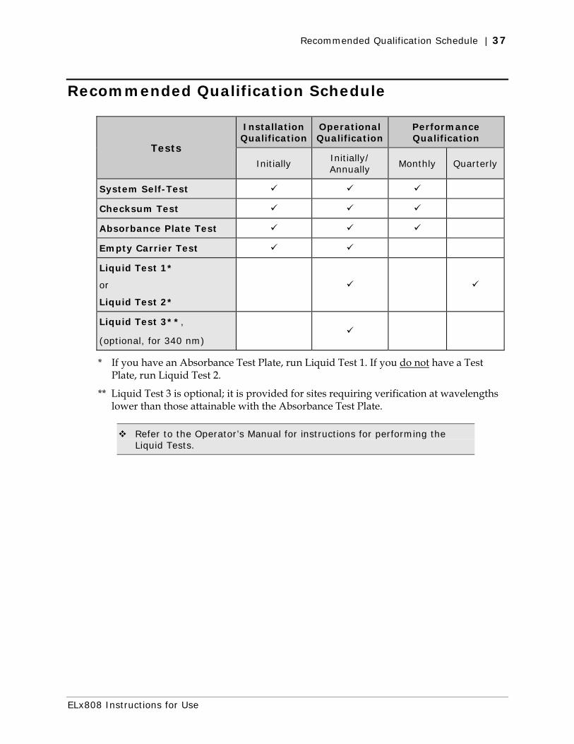
Recommended Qualification Schedule
Tests
Installation Qualification
Operational Qualification
Performance Qualification
Initially Initially/ Annually
Monthly Quarterly
System Self-Test
Checksum Test
Absorbance Plate Test
Empty Carrier Test
Liquid Test 1*
or
Liquid Test 2*
Liquid Test 3**,
(optional, for 340 nm)
* If you have an Absorbance Test Plate, run Liquid Test 1. If you do not have a Test Plate, run Liquid Test 2.
** Liquid Test 3 is optional; it is provided for sites requiring verification at wavelengths lower than those attainable with the Absorbance Test Plate.
Refer to the Operator’s Manual for instructions for performing the Liquid Tests.
ELx808 Instructions for Use

38 | Instrument Testing
Perform Tests Using the Instrument Keypad
From the Main Menu screen, select UTIL.
R E A D Y 0 1 : 3 0 P M 1 0 / 0 9 / 0 7
R E A D D E F I N E R E P O R T U T I L
S E L E C T U T I L I T Y O P T I O N ?
T E S T S S E T U P O U T P U T R E A D
• Select TESTS.
S E L E C T T E S T
S Y S T E M C H K S U M C A L P L T E
System Test
The System Self-Test confirms that the light levels and electronic noise at all installed filter wavelengths meet factory acceptance criteria. The air and dark readings are measured and evaluated to ensure that they fall within specified ranges.
The reader automatically runs a System Test each time it is powered on. An error will be displayed if the test fails. No printout will occur at the test. To obtain a printout, select UTIL > TESTS > SYSTEM. Results print in a pass/fail format using the printer attached to the reader.
The Optics portion of the System Self-Test report confirms that the reading channels have adequate signal range without saturating the electronics. The test also indicates if the light bulb is within operational limits.
Checksum Test
The Checksum Test runs automatically when the reader is powered on. The test compares the software to the internally recorded checksum values to ensure that the software has not been corrupted. If there are any errors during the test, they will be displayed. To verify the checksum, revisions, and version of software currently loaded onto your reader, select UTIL > TESTS > CHKSUM.
When the CHKSUM Test is selected, the basecode and assay configuration software versions and the software’s checksum appear on the display.
BioTek Instruments, Inc.

Perform Tests Using the Instrument Keypad | 39
Absorbance Plate Test
The Absorbance Plate Test, also referred to as the Universal or Calibration Plate Test, compares the reader’s optical density measurements and mechanical alignment to NIST-traceable values. Accuracy/linearity, repeatability, and alignment are tested. Specific standard calibration values must be entered from the test plate’s Data Sheet for each wavelength to be tested.
Important! The Absorbance Plate Test tests the accuracy and repeatability specifications from 0.000 to 2.500 OD only. In the example above, the Analysis report displays the OD values read in well positions D4 and E9 but does not indicate PASS or FAIL, because the values are higher than 2.500 OD and therefore are not within the test range.
Enter the Absorbance Plate Specifications
Using the Data Sheet provided with the Absorbance Test Plate (Part Number 7260522), enter the calibration values into the reader:
From the Main Menu:
R E A D Y 9 : 4 5 P M 1 0 / 0 9 / 0 7
R E A D D E F I N E R E P O R T U T I L
• Select UTIL.
S E L E C T U T I L I T Y O P T I O N ?
T E S T S S E T U P O U T P U T R E A D
• Select SETUP.
E D I T S E T U P I N F O R M A T I O N
D A T E T I M E F I L T E R * M O R E
• Select MORE*.
E D I T S E T U P I N F O R M A T I O N ?
R S 2 3 2 C A L P L A T E * M O R E
• At the second EDIT SETUP menu, press SOFT KEY 2 or 3 to access the CALIBRATION FILTER menu.
C A L I B R A T I O N F I L T E R : 4 0 5
4 0 5 4 5 0 4 9 0 6 3 0
ELx808 Instructions for Use

40 | Instrument Testing
• Select the soft key beneath the desired filter wavelength.
• Press ENTER to advance to the menu that allows entry of Well Location and calibration values.
W A V E L E N G T H : 4 0 5 W E L L : C 0 1
C A L I B R A T I O N V A L U E S : 0 . 0 0 0
• Refer to the Absorbance Plate Data Sheet. Enter the absorbance value associated with the selected wavelength for the displayed well location.
• After each entry, press ENTER to advance to the next consecutive well location.
• Repeat for the remaining filter wavelengths.
• When all calibration values have been entered, press the Main Menu key.
Run the Absorbance Plate Test
From the reader’s Main Menu display, select UTIL > TESTS > CALPLTE:
S E L E C T T E S T ?
S Y S T E M C H K S U M C A L P L T E
• The test is run using one filter wavelength. Select the desired
wavelength from the CALIBRATION FILTER screen.
C A L I B R A T I O N F I L T E R : 4 0 5
4 0 5 4 5 0 4 9 0 6 3 0
• When prompted, insert the absorbance test plate into the reader’s plate
carrier, and press the READ key to begin the calibration program.
When the test is complete, the results will print.
The Absorbance Plate Test Report
The Absorbance Plate Test Report contains results for the following:
• Alignment: This portion of the test measures the alignment of the microplate carrier with the optical path. A reading of > 0.015 OD represents an out-of-alignment condition. Wells A01, A12, H01, and H12 are the only valid alignment holes for the reader on the 7260522 Test Plate.
BioTek Instruments, Inc.

Perform Tests Using Gen5 | 41
• Accuracy/Linearity: Accuracy is a measure of the absorbance (optical density) of Test Plate wells C01, D04, E02, F05, G03 and H06 compared to known standard values contained in the data sheet that accompanies each Test Plate. If the accuracy specifications are met, then the reader also proves to be linear.
• Repeatability: This parameter is a measure of the instrument's ability to read the same well with minimum variation between two reads with the well in the same location.
• Channel-to-Channel Variation: This is tested using the turnaround test, which is shown on the second repeatability test.
Test Failures
If any of the test parameters report as "FAIL", confirm that the standard values on the test plate data sheet match the values on the printout. If you find an error, correct and retest. If the test still fails, please contact BioTek's Technical Assistance Center. Please have a copy of the test and the reader’s serial number available when you call.
Empty Carrier Test
The Empty Carrier Test confirms the ELx808’s read capabilities at the 100% light level, and can help to identify deteriorating interference wavelength filters and other optical problems.
1. Run a simple endpoint assay, at every filter value listed in the Wavelength table, with no plate in the carrier. Do not apply blanking or transformations.
2. Examine the OD values on the printouts. Every OD should read 0.000 ± 0.004 OD.
Note: These limits are required by BioTek and cannot be changed.
Perform Tests Using Gen5
System Self-Test and Absorbance Plate Test
The System Self-Test and Absorbance Plate Test may be run via Gen5 installed on a host computer. Refer to the Operator’s Manual or documentation supplied with the software package for instructions.
ELx808 Instructions for Use

42 | Instrument Testing
BioTek Instruments, Inc.

Specifications

44 | Specifications
Technical Specifications
All Models
Microplates
All models accommodate standard 96-well, flat- or round-bottom microplates
Hardware and Environmental
Display: 2-line x 24 character LCD
Light Source: Tungsten halogen-filled bulb, with 500 hours average life
Dimensions: 16.0" D x 15.5" W x 8.75" H
(40.6 cm x 39.37 cm x 22.2 cm)
Weight: 35 lb. maximum (15.87 kg maximum)
Environment: Operating temperature 18° to 40°C (64° to 104°F)
Humidity: 10% to 85% noncondensing
Power Source: Readers manufactured before December 2005:
Internal, adjustable power input module; four voltage ranges are accommodated by the voltage selection switch:
100 V~ 90 to 110 V~, 50 to 60 Hz
120 V~ 108 to 132 V~, 50 to 60 Hz
230 V~ 207 to 253 V~, 50 to 60 Hz
240 V~ 216 to 264 V~, 50 to 60 Hz
Readers manufactured after December 2005:
24-volt external power supply compatible with 100-240 V~ ± 10% @ 50-60 Hz
Power Consumption: 100 VA
Reading Speeds
Single wavelength: 8 seconds, rapid mode; 12 seconds, normal/regular mode
Dual wavelength: 13 seconds, rapid mode; 20 seconds, normal/regular mode
Single wavelength higher than 400 nm: 6 seconds from A1 to A1, kinetic rapid mode
BioTek Instruments, Inc.

Technical Specifications | 45
Standard Model
General
λ range: 380 to 900 nm
Filters: 10 nm half-bandwidth interference filters
User-accessible filter wheel; up to 6 filters may be installed on the instrument at one time
Filters supplied: 405, 450, 490, 630 nm and two blank filters
Absorbance Measurement Range:
0.000 to 4.000 OD
Optical
Single-wavelength endpoint measurements, 12-second read (normal/regular read mode). For the performance described here, the Gain on the Optics Test should be below 20.
Accuracy: ± 1.0% ± 0.010 OD from 0.000 to 2.500 OD @ 405 nm
Linearity: ± 1.0% from 0.000 to 2.500 OD at 405 nm
± 2.0% from 2.500 OD to 3.500 OD @ 405 nm
Repeatability: ± 0.5% ± 0.005 OD from 0.000 to 2.500 OD @ 405 nm
± 1.5% ± 0.005 OD from 2.500 to 3.500 OD @ 405 nm
± 2.5% ± 0.005 OD from 3.500 to 4.000 OD @ 405 nm
Single-wavelength kinetic measurements, read intervals < 12 seconds
Accuracy: ± 2.0% ± 0.010 OD from 0.000 to 2.500 OD @ 405 nm
Linearity: ± 2.0% from 0.000 to 2.500 OD @ 405 nm
Repeatability: ± 1.0% ± 0.010 OD from 0.000 to 2.500 OD @ 405 nm
ELx808 Instructions for Use

46 | Specifications
BioTek Instruments, Inc.
Ultraviolet (“UV”)/Incubator Model
General
λ range: 340 to 900 nm
Filters: 10 nm half-bandwidth interference filters
User-accessible filter wheel; up to 6 filters may be installed on the instrument at one time
Filters supplied: 340, 405, 450, 490, 630 nm and one blank filter
Absorbance Measurement Range:
0.000 to 4.000 OD for 400 to 900 nm range
0.000 to 3.000 OD for 340 to 400 nm range
Optical
400 to 900 nm range
Accuracy, Linearity, Repeatability:
Same as for standard model
340 to 400 nm range
Accuracy: ± 1.0% ± 0.010 OD from 0.000 to 2.000 OD @ 340 nm
Linearity: ± 1.0% from 0.000 to 2.000 OD @ 340 nm
Repeatability: ± 1.0% ± 0.005 OD from 0.000 to 2.000 OD @ 340 nm
Incubation
Temperature Control: Temperature controlled to 50°C
Temperature Variation: ± 0.50°C @37°C (with the plate sealed)
(Optional) Internal Barcode Reader
If equipped, the internal barcode reader recognizes a number of common barcode types during the plate read operation. (The barcode identifies the plate.) The reader’s barcode option is compatible with the following barcode types:
CODABAR CODE 128 CODE 39 UPC INTERLEAVED 2 of 5 EAN CODE 11 MSI CODE 93 PLESSEY
(Optional) Robot Interface
The robot interface (model-R) allows the reader to function with an autoloading robot. Using computer control commands from a host PC, the user can manage reader functions in conjunction with the robotic system. The robot interface model can be configured with all options available for the standard ELx808.
Recommended