Operational Amplifier Frequency ResponseActive Filters
ElectronicsOperational Amplifier Dynamic Characteristics
Terry Sturtevant
Wilfrid Laurier University
September 4, 2014
Terry Sturtevant Electronics Operational Amplifier Dynamic Characteristics
Operational Amplifier Frequency ResponseActive Filters Slew Rate
Op amp frequency response
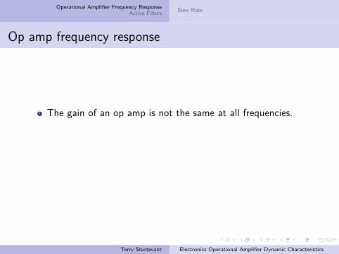
The gain of an op amp is not the same at all frequencies.The open loop gain is the gain without feedback.Open loop gain is constant at low frequencies,but then starts to decrease at higher frequencies.
Terry Sturtevant Electronics Operational Amplifier Dynamic Characteristics
Operational Amplifier Frequency ResponseActive Filters Slew Rate
Op amp frequency response
The gain of an op amp is not the same at all frequencies.
The open loop gain is the gain without feedback.Open loop gain is constant at low frequencies,but then starts to decrease at higher frequencies.
Terry Sturtevant Electronics Operational Amplifier Dynamic Characteristics
Operational Amplifier Frequency ResponseActive Filters Slew Rate
Op amp frequency response
The gain of an op amp is not the same at all frequencies.The open loop gain is the gain without feedback.
Open loop gain is constant at low frequencies,but then starts to decrease at higher frequencies.
Terry Sturtevant Electronics Operational Amplifier Dynamic Characteristics
Operational Amplifier Frequency ResponseActive Filters Slew Rate
Op amp frequency response
The gain of an op amp is not the same at all frequencies.The open loop gain is the gain without feedback.Open loop gain is constant at low frequencies,
but then starts to decrease at higher frequencies.
Terry Sturtevant Electronics Operational Amplifier Dynamic Characteristics
Operational Amplifier Frequency ResponseActive Filters Slew Rate
Op amp frequency response
The gain of an op amp is not the same at all frequencies.The open loop gain is the gain without feedback.Open loop gain is constant at low frequencies,but then starts to decrease at higher frequencies.
Terry Sturtevant Electronics Operational Amplifier Dynamic Characteristics
Operational Amplifier Frequency ResponseActive Filters Slew Rate
6V
4V6V
4V
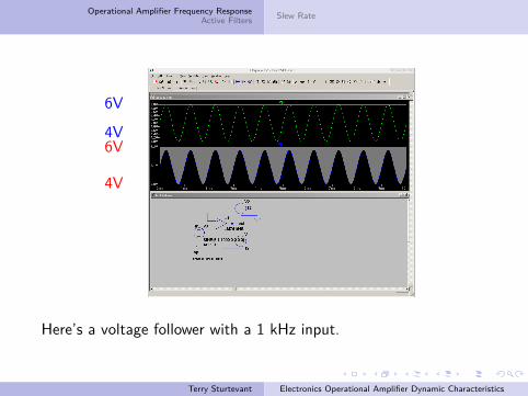
Here’s a voltage follower with a 1 kHz input.
Terry Sturtevant Electronics Operational Amplifier Dynamic Characteristics
Operational Amplifier Frequency ResponseActive Filters Slew Rate
6V
4V6V
4V
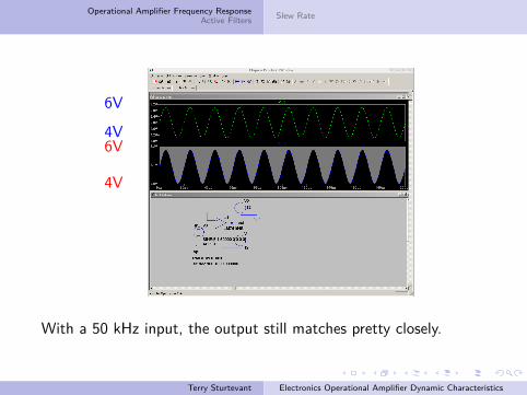
With a 50 kHz input, the output still matches pretty closely.
Terry Sturtevant Electronics Operational Amplifier Dynamic Characteristics
Operational Amplifier Frequency ResponseActive Filters Slew Rate
6V
4V6V
4V
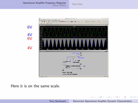
Here it is on the same scale.
Terry Sturtevant Electronics Operational Amplifier Dynamic Characteristics
Operational Amplifier Frequency ResponseActive Filters Slew Rate
6V
4V5.8V
4.2V
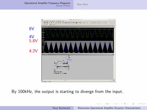
By 100kHz, the output is starting to diverge from the input.
Terry Sturtevant Electronics Operational Amplifier Dynamic Characteristics
Operational Amplifier Frequency ResponseActive Filters Slew Rate
6V
4V6V
4V
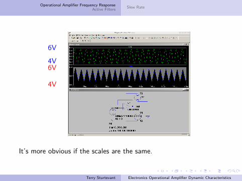
It’s more obvious if the scales are the same.
Terry Sturtevant Electronics Operational Amplifier Dynamic Characteristics
Operational Amplifier Frequency ResponseActive Filters Slew Rate
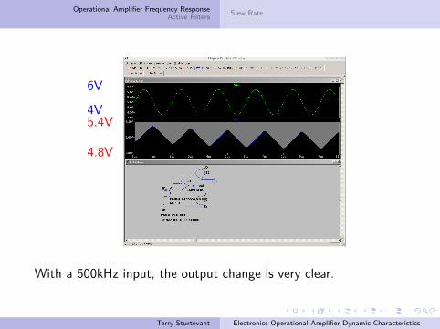
6V
4V5.4V
4.8V
With a 500kHz input, the output change is very clear.
Terry Sturtevant Electronics Operational Amplifier Dynamic Characteristics

Operational Amplifier Frequency ResponseActive Filters Slew Rate
6V
4V6V
4V
On the same scale, it’s obvious.
Terry Sturtevant Electronics Operational Amplifier Dynamic Characteristics
Operational Amplifier Frequency ResponseActive Filters Slew Rate
The rolloff can be seen in the next figures.
Terry Sturtevant Electronics Operational Amplifier Dynamic Characteristics
Operational Amplifier Frequency ResponseActive Filters Slew Rate
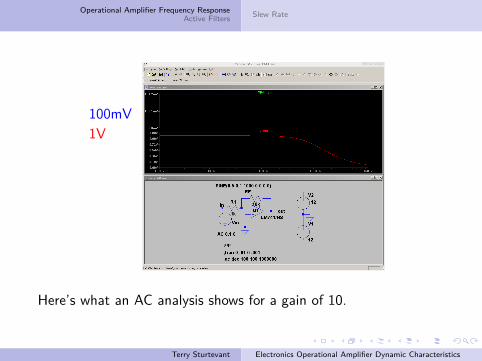
100mV1V
Here’s what an AC analysis shows for a gain of 10.
Terry Sturtevant Electronics Operational Amplifier Dynamic Characteristics
Operational Amplifier Frequency ResponseActive Filters Slew Rate
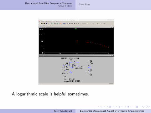
A logarithmic scale is helpful sometimes.
Terry Sturtevant Electronics Operational Amplifier Dynamic Characteristics
Operational Amplifier Frequency ResponseActive Filters Slew Rate
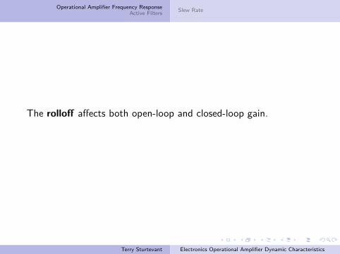
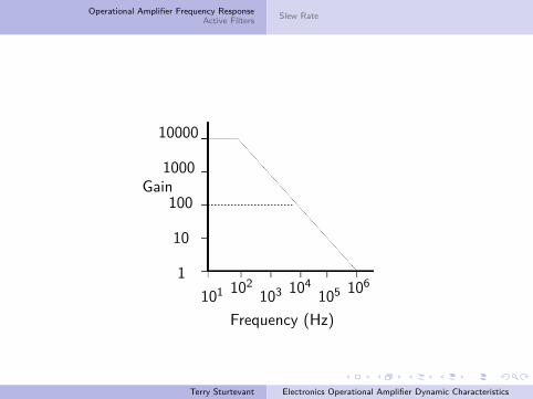
The rolloff affects both open-loop and closed-loop gain.
Terry Sturtevant Electronics Operational Amplifier Dynamic Characteristics
Operational Amplifier Frequency ResponseActive Filters Slew Rate
1
10
100
1000
10000
Gain
101 102103 104
105 106
Frequency (Hz)
Terry Sturtevant Electronics Operational Amplifier Dynamic Characteristics

Operational Amplifier Frequency ResponseActive Filters Slew Rate
1
10
100
1000
10000
Gain
101 102103 104
105 106
Frequency (Hz)
open loop gain��
Terry Sturtevant Electronics Operational Amplifier Dynamic Characteristics
Operational Amplifier Frequency ResponseActive Filters Slew Rate
1
10
100
1000
10000
Gain
101 102103 104
105 106
Frequency (Hz)
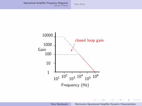
closed loop gain���
Terry Sturtevant Electronics Operational Amplifier Dynamic Characteristics

Operational Amplifier Frequency ResponseActive Filters Slew Rate
1
10
100
1000
10000
Gain
101 102103 104
105 106
Frequency (Hz)
rolloff 20dbper decade
PPi
Terry Sturtevant Electronics Operational Amplifier Dynamic Characteristics
Operational Amplifier Frequency ResponseActive Filters Slew Rate
1
10
100
1000
10000
Gain
101 102103 104
105 106
Frequency (Hz)
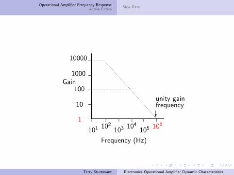
unity gainfrequency?
Terry Sturtevant Electronics Operational Amplifier Dynamic Characteristics
Operational Amplifier Frequency ResponseActive Filters Slew Rate
1
10
100
1000
10000
Gain
101 102103 104
105 106
Frequency (Hz)
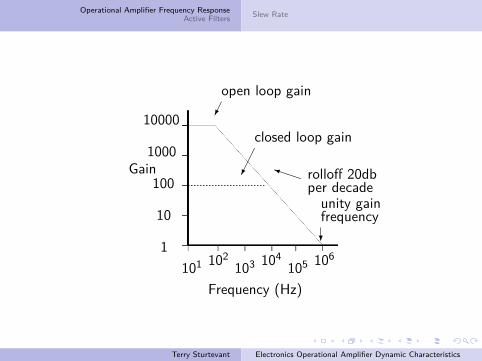
open loop gain��
closed loop gain��� rolloff 20db
per decadePPi
unity gainfrequency?
Terry Sturtevant Electronics Operational Amplifier Dynamic Characteristics
Operational Amplifier Frequency ResponseActive Filters Slew Rate
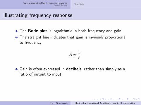
Illustrating frequency response
The Bode plot is logarithmic in both frequency and gain.The straight line indicates that gain is inversely proportionalto frequency
A ∝ 1f
Gain is often expressed in decibels, rather than simply as aratio of output to inputSo
Gdb = 20 log(Vo
Vi
)
Terry Sturtevant Electronics Operational Amplifier Dynamic Characteristics
Operational Amplifier Frequency ResponseActive Filters Slew Rate
Illustrating frequency response
The Bode plot is logarithmic in both frequency and gain.
The straight line indicates that gain is inversely proportionalto frequency
A ∝ 1f
Gain is often expressed in decibels, rather than simply as aratio of output to inputSo
Gdb = 20 log(Vo
Vi
)
Terry Sturtevant Electronics Operational Amplifier Dynamic Characteristics
Operational Amplifier Frequency ResponseActive Filters Slew Rate
Illustrating frequency response
The Bode plot is logarithmic in both frequency and gain.The straight line indicates that gain is inversely proportionalto frequency
A ∝ 1f
Gain is often expressed in decibels, rather than simply as aratio of output to inputSo
Gdb = 20 log(Vo
Vi
)
Terry Sturtevant Electronics Operational Amplifier Dynamic Characteristics
Operational Amplifier Frequency ResponseActive Filters Slew Rate
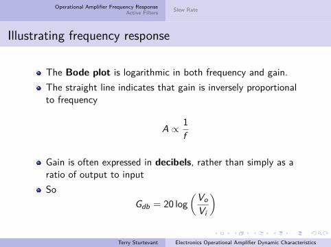
Illustrating frequency response
The Bode plot is logarithmic in both frequency and gain.The straight line indicates that gain is inversely proportionalto frequency
A ∝ 1f
Gain is often expressed in decibels, rather than simply as aratio of output to input
SoGdb = 20 log
(VoVi
)
Terry Sturtevant Electronics Operational Amplifier Dynamic Characteristics
Operational Amplifier Frequency ResponseActive Filters Slew Rate
Illustrating frequency response
The Bode plot is logarithmic in both frequency and gain.The straight line indicates that gain is inversely proportionalto frequency
A ∝ 1f
Gain is often expressed in decibels, rather than simply as aratio of output to inputSo
Gdb = 20 log(Vo
Vi
)
Terry Sturtevant Electronics Operational Amplifier Dynamic Characteristics
Operational Amplifier Frequency ResponseActive Filters Slew Rate
Gdb = 20 log(Vo
Vi
)
A change by a factor of 10 in(
VoVi
)is a change of 20 db.
A decade is a factor of 10, so rolloff of 20 db/decaderepresents a decrease in
(VoVi
)of a factor of 10 as the
frequency increases by a factor of 10.
Terry Sturtevant Electronics Operational Amplifier Dynamic Characteristics
Operational Amplifier Frequency ResponseActive Filters Slew Rate
Gdb = 20 log(Vo
Vi
)A change by a factor of 10 in
(VoVi
)is a change of 20 db.
A decade is a factor of 10, so rolloff of 20 db/decaderepresents a decrease in
(VoVi
)of a factor of 10 as the
frequency increases by a factor of 10.
Terry Sturtevant Electronics Operational Amplifier Dynamic Characteristics
Operational Amplifier Frequency ResponseActive Filters Slew Rate
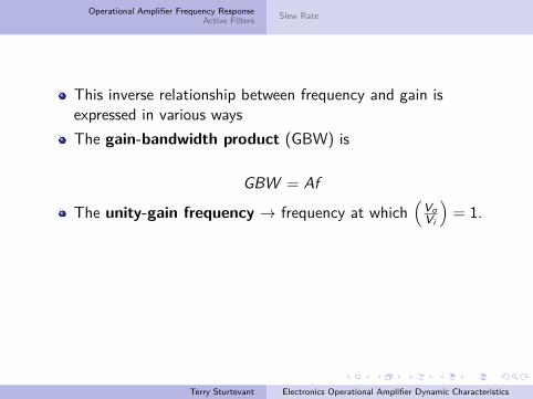
This inverse relationship between frequency and gain isexpressed in various ways
The gain-bandwidth product (GBW) is
GBW = Af
The unity-gain frequency → frequency at which(
VoVi
)= 1.
(I will use the term A to refer to(
VoVi
)and G to denote the
gain in decibels, as described above. This convention iscommon, but not universal, so when consulting information onthe subject be sure to pay attention to how gain is expressed.)
Terry Sturtevant Electronics Operational Amplifier Dynamic Characteristics

Operational Amplifier Frequency ResponseActive Filters Slew Rate
This inverse relationship between frequency and gain isexpressed in various waysThe gain-bandwidth product (GBW) is
GBW = Af
The unity-gain frequency → frequency at which(
VoVi
)= 1.
(I will use the term A to refer to(
VoVi
)and G to denote the
gain in decibels, as described above. This convention iscommon, but not universal, so when consulting information onthe subject be sure to pay attention to how gain is expressed.)
Terry Sturtevant Electronics Operational Amplifier Dynamic Characteristics
Operational Amplifier Frequency ResponseActive Filters Slew Rate
Relationship between open loop and closed loop gainWhen negative feedback is employed in an op amp circuit, theclosed-loop gain is decreased.
As frequency increases, and the open-loop gain decreases dueto rolloff, the values of open-loop and closed-loop gaineventually coincide.From this point on, the closed loop gain also begins toexperience rolloff at the same rate.Thus the unity-gain frequency for an op amp circuit is thesame, regardless of the mid-band gain.
Terry Sturtevant Electronics Operational Amplifier Dynamic Characteristics
Operational Amplifier Frequency ResponseActive Filters Slew Rate
Relationship between open loop and closed loop gainWhen negative feedback is employed in an op amp circuit, theclosed-loop gain is decreased.As frequency increases, and the open-loop gain decreases dueto rolloff, the values of open-loop and closed-loop gaineventually coincide.
From this point on, the closed loop gain also begins toexperience rolloff at the same rate.Thus the unity-gain frequency for an op amp circuit is thesame, regardless of the mid-band gain.
Terry Sturtevant Electronics Operational Amplifier Dynamic Characteristics
Operational Amplifier Frequency ResponseActive Filters Slew Rate
Relationship between open loop and closed loop gainWhen negative feedback is employed in an op amp circuit, theclosed-loop gain is decreased.As frequency increases, and the open-loop gain decreases dueto rolloff, the values of open-loop and closed-loop gaineventually coincide.From this point on, the closed loop gain also begins toexperience rolloff at the same rate.
Thus the unity-gain frequency for an op amp circuit is thesame, regardless of the mid-band gain.
Terry Sturtevant Electronics Operational Amplifier Dynamic Characteristics
Operational Amplifier Frequency ResponseActive Filters Slew Rate
Relationship between open loop and closed loop gainWhen negative feedback is employed in an op amp circuit, theclosed-loop gain is decreased.As frequency increases, and the open-loop gain decreases dueto rolloff, the values of open-loop and closed-loop gaineventually coincide.From this point on, the closed loop gain also begins toexperience rolloff at the same rate.Thus the unity-gain frequency for an op amp circuit is thesame, regardless of the mid-band gain.
Terry Sturtevant Electronics Operational Amplifier Dynamic Characteristics
Operational Amplifier Frequency ResponseActive Filters Slew Rate
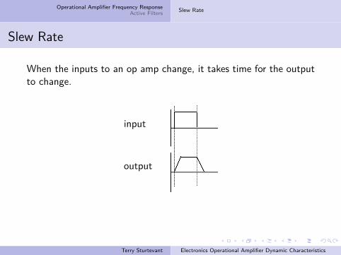
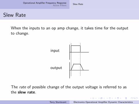
Slew Rate
When the inputs to an op amp change, it takes time for the outputto change.
input
output
The rate of possible change of the output voltage is referred to asthe slew rate.
Terry Sturtevant Electronics Operational Amplifier Dynamic Characteristics
Operational Amplifier Frequency ResponseActive Filters Slew Rate
Slew Rate
When the inputs to an op amp change, it takes time for the outputto change.
input
output
The rate of possible change of the output voltage is referred to asthe slew rate.
Terry Sturtevant Electronics Operational Amplifier Dynamic Characteristics

Operational Amplifier Frequency ResponseActive Filters Slew Rate
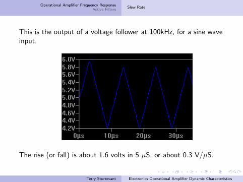
This is the output of a voltage follower at 100kHz, for a sine waveinput.
The rise (or fall) is about 1.6 volts in 5 µS, or about 0.3 V/µS.
Terry Sturtevant Electronics Operational Amplifier Dynamic Characteristics

Operational Amplifier Frequency ResponseActive Filters Slew Rate
This is the output of a voltage follower at 100kHz, for a sine waveinput.
The rise (or fall) is about 1.6 volts in 5 µS, or about 0.3 V/µS.
Terry Sturtevant Electronics Operational Amplifier Dynamic Characteristics
Operational Amplifier Frequency ResponseActive Filters Slew Rate
This is the output of a voltage follower at 100kHz, for a sine waveinput.
The rise (or fall) is about 1.6 volts in 5 µS, or about 0.3 V/µS.
Terry Sturtevant Electronics Operational Amplifier Dynamic Characteristics
Operational Amplifier Frequency ResponseActive Filters Slew Rate
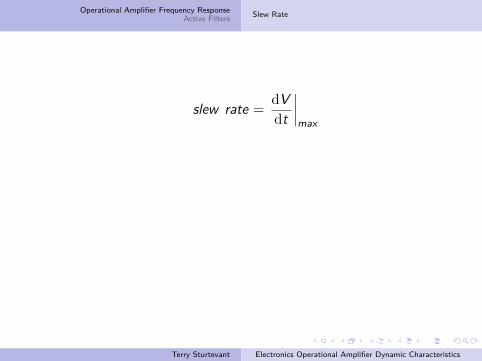
The slew rate of an operational amplifier is defined as themaximum rate of change of voltage output.
Terry Sturtevant Electronics Operational Amplifier Dynamic Characteristics
Operational Amplifier Frequency ResponseActive Filters Slew Rate
The slew rate of an operational amplifier is defined as themaximum rate of change of voltage output.Slew rate is usually given in V /µS.
Terry Sturtevant Electronics Operational Amplifier Dynamic Characteristics
Operational Amplifier Frequency ResponseActive Filters Slew Rate
The slew rate of an operational amplifier is defined as themaximum rate of change of voltage output.Slew rate is usually given in V /µS.
slew rate =dVdt
∣∣∣∣max
Terry Sturtevant Electronics Operational Amplifier Dynamic Characteristics
Operational Amplifier Frequency ResponseActive Filters Slew Rate
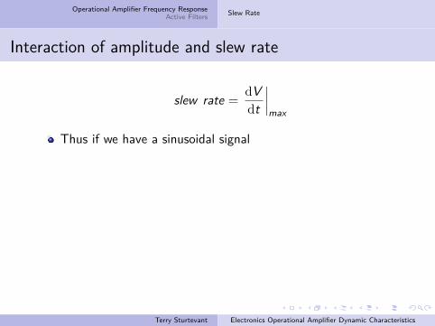
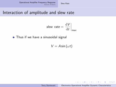
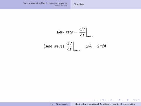
Interaction of amplitude and slew rate
slew rate =dVdt
∣∣∣∣max
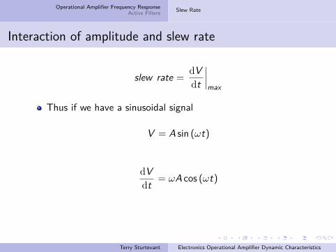
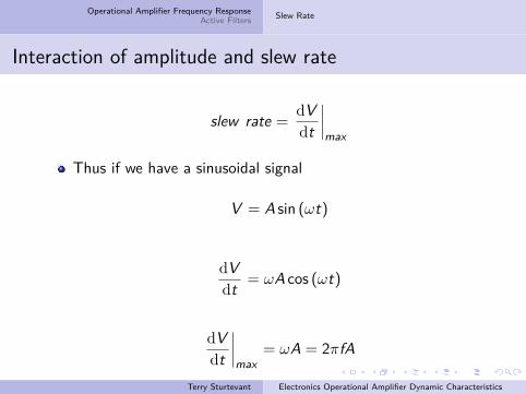
Thus if we have a sinusoidal signal
V = A sin (ωt)
dVdt = ωA cos (ωt)
dVdt
∣∣∣∣max
= ωA = 2πfA
Terry Sturtevant Electronics Operational Amplifier Dynamic Characteristics
Operational Amplifier Frequency ResponseActive Filters Slew Rate
Interaction of amplitude and slew rate
slew rate =dVdt
∣∣∣∣max
Thus if we have a sinusoidal signal
V = A sin (ωt)
dVdt = ωA cos (ωt)
dVdt
∣∣∣∣max
= ωA = 2πfA
Terry Sturtevant Electronics Operational Amplifier Dynamic Characteristics
Operational Amplifier Frequency ResponseActive Filters Slew Rate
Interaction of amplitude and slew rate
slew rate =dVdt
∣∣∣∣max
Thus if we have a sinusoidal signal
V = A sin (ωt)
dVdt = ωA cos (ωt)
dVdt
∣∣∣∣max
= ωA = 2πfA
Terry Sturtevant Electronics Operational Amplifier Dynamic Characteristics
Operational Amplifier Frequency ResponseActive Filters Slew Rate
Interaction of amplitude and slew rate
slew rate =dVdt
∣∣∣∣max
Thus if we have a sinusoidal signal
V = A sin (ωt)
dVdt = ωA cos (ωt)
dVdt
∣∣∣∣max
= ωA = 2πfA
Terry Sturtevant Electronics Operational Amplifier Dynamic Characteristics
Operational Amplifier Frequency ResponseActive Filters Slew Rate
Interaction of amplitude and slew rate
slew rate =dVdt
∣∣∣∣max
Thus if we have a sinusoidal signal
V = A sin (ωt)
dVdt = ωA cos (ωt)
dVdt
∣∣∣∣max
= ωA = 2πfA
Terry Sturtevant Electronics Operational Amplifier Dynamic Characteristics
Operational Amplifier Frequency ResponseActive Filters Slew Rate
Interaction of amplitude and slew rate
slew rate =dVdt
∣∣∣∣max
Thus if we have a sinusoidal signal
V = A sin (ωt)
dVdt = ωA cos (ωt)
dVdt
∣∣∣∣max
= ωA = 2πfA
Terry Sturtevant Electronics Operational Amplifier Dynamic Characteristics
Operational Amplifier Frequency ResponseActive Filters Slew Rate
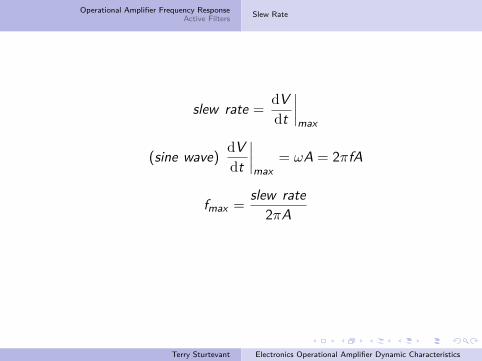
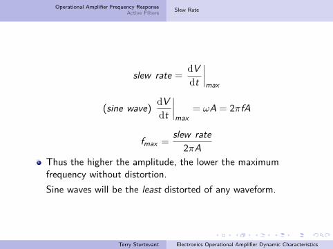
slew rate =dVdt
∣∣∣∣max
(sine wave) dVdt
∣∣∣∣max
= ωA = 2πfA
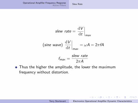
fmax =slew rate
2πAThus the higher the amplitude, the lower the maximumfrequency without distortion.Sine waves will be the least distorted of any waveform.
Terry Sturtevant Electronics Operational Amplifier Dynamic Characteristics
Operational Amplifier Frequency ResponseActive Filters Slew Rate
slew rate =dVdt
∣∣∣∣max
(sine wave) dVdt
∣∣∣∣max
= ωA = 2πfA
fmax =slew rate
2πA
Thus the higher the amplitude, the lower the maximumfrequency without distortion.Sine waves will be the least distorted of any waveform.
Terry Sturtevant Electronics Operational Amplifier Dynamic Characteristics
Operational Amplifier Frequency ResponseActive Filters Slew Rate
slew rate =dVdt
∣∣∣∣max
(sine wave) dVdt
∣∣∣∣max
= ωA = 2πfA
fmax =slew rate
2πAThus the higher the amplitude, the lower the maximumfrequency without distortion.
Sine waves will be the least distorted of any waveform.
Terry Sturtevant Electronics Operational Amplifier Dynamic Characteristics
Operational Amplifier Frequency ResponseActive Filters Slew Rate
slew rate =dVdt
∣∣∣∣max
(sine wave) dVdt
∣∣∣∣max
= ωA = 2πfA
fmax =slew rate
2πAThus the higher the amplitude, the lower the maximumfrequency without distortion.Sine waves will be the least distorted of any waveform.
Terry Sturtevant Electronics Operational Amplifier Dynamic Characteristics

Operational Amplifier Frequency ResponseActive Filters Slew Rate
6V
4V6V
4V
Here’s a previous circuit; 1V, 500kHz into a voltage follower.
Terry Sturtevant Electronics Operational Amplifier Dynamic Characteristics
Operational Amplifier Frequency ResponseActive Filters Slew Rate
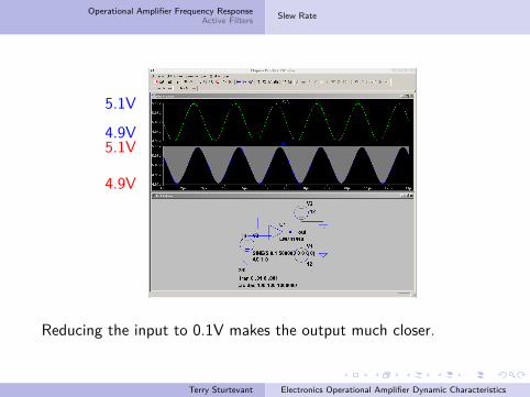
5.1V
4.9V5.1V
4.9V
Reducing the input to 0.1V makes the output much closer.
Terry Sturtevant Electronics Operational Amplifier Dynamic Characteristics
Operational Amplifier Frequency ResponseActive Filters
Low Pass FiltersHigh Pass FiltersBand Pass Filters
Active filtersOne of the uses of op amps is to produce circuits which areused to amplify or attenuate a certain range of frequencies.
These are called active filters.
Terry Sturtevant Electronics Operational Amplifier Dynamic Characteristics
Operational Amplifier Frequency ResponseActive Filters
Low Pass FiltersHigh Pass FiltersBand Pass Filters
Active filtersOne of the uses of op amps is to produce circuits which areused to amplify or attenuate a certain range of frequencies.These are called active filters.
Terry Sturtevant Electronics Operational Amplifier Dynamic Characteristics
Operational Amplifier Frequency ResponseActive Filters
Low Pass FiltersHigh Pass FiltersBand Pass Filters
Low Pass FiltersA low pass filter allows frequencies below a certain cornerfrequency fc to pass, and attenuates those above.
Note that the corner frequency is not an absolute limit; it isthe point at which attenuation begins.Actually it’s the “3 db point” at which the gain differs fromthe mid-band gain by 3db.Expressing gain without using decibels, it’s the point at whichthe gain is the mid-band gain divided by
√2.
A low pass filter and its Bode plot are shown in the followingfigures.(Note: there are numerous designs for filters; the ones shownhere are simple to analyze.)
Terry Sturtevant Electronics Operational Amplifier Dynamic Characteristics

Operational Amplifier Frequency ResponseActive Filters
Low Pass FiltersHigh Pass FiltersBand Pass Filters
Low Pass FiltersA low pass filter allows frequencies below a certain cornerfrequency fc to pass, and attenuates those above.Note that the corner frequency is not an absolute limit; it isthe point at which attenuation begins.
Actually it’s the “3 db point” at which the gain differs fromthe mid-band gain by 3db.Expressing gain without using decibels, it’s the point at whichthe gain is the mid-band gain divided by
√2.
A low pass filter and its Bode plot are shown in the followingfigures.(Note: there are numerous designs for filters; the ones shownhere are simple to analyze.)
Terry Sturtevant Electronics Operational Amplifier Dynamic Characteristics
Operational Amplifier Frequency ResponseActive Filters
Low Pass FiltersHigh Pass FiltersBand Pass Filters
Low Pass FiltersA low pass filter allows frequencies below a certain cornerfrequency fc to pass, and attenuates those above.Note that the corner frequency is not an absolute limit; it isthe point at which attenuation begins.Actually it’s the “3 db point” at which the gain differs fromthe mid-band gain by 3db.
Expressing gain without using decibels, it’s the point at whichthe gain is the mid-band gain divided by
√2.
A low pass filter and its Bode plot are shown in the followingfigures.(Note: there are numerous designs for filters; the ones shownhere are simple to analyze.)
Terry Sturtevant Electronics Operational Amplifier Dynamic Characteristics
Operational Amplifier Frequency ResponseActive Filters
Low Pass FiltersHigh Pass FiltersBand Pass Filters
Low Pass FiltersA low pass filter allows frequencies below a certain cornerfrequency fc to pass, and attenuates those above.Note that the corner frequency is not an absolute limit; it isthe point at which attenuation begins.Actually it’s the “3 db point” at which the gain differs fromthe mid-band gain by 3db.Expressing gain without using decibels, it’s the point at whichthe gain is the mid-band gain divided by
√2.
A low pass filter and its Bode plot are shown in the followingfigures.
(Note: there are numerous designs for filters; the ones shownhere are simple to analyze.)
Terry Sturtevant Electronics Operational Amplifier Dynamic Characteristics
Operational Amplifier Frequency ResponseActive Filters
Low Pass FiltersHigh Pass FiltersBand Pass Filters
Low Pass FiltersA low pass filter allows frequencies below a certain cornerfrequency fc to pass, and attenuates those above.Note that the corner frequency is not an absolute limit; it isthe point at which attenuation begins.Actually it’s the “3 db point” at which the gain differs fromthe mid-band gain by 3db.Expressing gain without using decibels, it’s the point at whichthe gain is the mid-band gain divided by
√2.
A low pass filter and its Bode plot are shown in the followingfigures.(Note: there are numerous designs for filters; the ones shownhere are simple to analyze.)
Terry Sturtevant Electronics Operational Amplifier Dynamic Characteristics
Operational Amplifier Frequency ResponseActive Filters
Low Pass FiltersHigh Pass FiltersBand Pass Filters
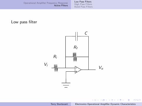
Low pass filter
C
Ri
Vi
Rf
Vo
Terry Sturtevant Electronics Operational Amplifier Dynamic Characteristics
Operational Amplifier Frequency ResponseActive Filters
Low Pass FiltersHigh Pass FiltersBand Pass Filters
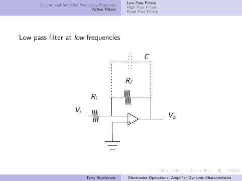
Low pass filter at low frequencies
C
Ri
Vi
Rf
Vo
Terry Sturtevant Electronics Operational Amplifier Dynamic Characteristics

Operational Amplifier Frequency ResponseActive Filters
Low Pass FiltersHigh Pass FiltersBand Pass Filters
Low pass filter at high frequencies
C
Ri
Vi
Rf
Vo
Terry Sturtevant Electronics Operational Amplifier Dynamic Characteristics

Operational Amplifier Frequency ResponseActive Filters
Low Pass FiltersHigh Pass FiltersBand Pass Filters
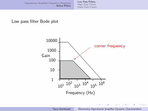
Low pass filter Bode plot
1
10
100
1000
10000
Gain
101 102103 104
105 106
Frequency (Hz)
passband��
���
Terry Sturtevant Electronics Operational Amplifier Dynamic Characteristics
Operational Amplifier Frequency ResponseActive Filters
Low Pass FiltersHigh Pass FiltersBand Pass Filters
Low pass filter Bode plot
1
10
100
1000
10000
Gain
101 102103 104
105 106
Frequency (Hz)
corner frequency��
��=
Terry Sturtevant Electronics Operational Amplifier Dynamic Characteristics
Operational Amplifier Frequency ResponseActive Filters
Low Pass FiltersHigh Pass FiltersBand Pass Filters
Low pass filterIn the feedback part of the circuit, at low frequencies Xc ≈ ∞and so the gain is that of a normal inverting amplifier.
As the frequency increases, at a corner frequency Xc = Rf .Above this frequency,
Z ∝ 1f
since Xc < Rf .
Terry Sturtevant Electronics Operational Amplifier Dynamic Characteristics
Operational Amplifier Frequency ResponseActive Filters
Low Pass FiltersHigh Pass FiltersBand Pass Filters
Low pass filterIn the feedback part of the circuit, at low frequencies Xc ≈ ∞and so the gain is that of a normal inverting amplifier.As the frequency increases, at a corner frequency Xc = Rf .
Above this frequency,
Z ∝ 1f
since Xc < Rf .
Terry Sturtevant Electronics Operational Amplifier Dynamic Characteristics
Operational Amplifier Frequency ResponseActive Filters
Low Pass FiltersHigh Pass FiltersBand Pass Filters
Low pass filterIn the feedback part of the circuit, at low frequencies Xc ≈ ∞and so the gain is that of a normal inverting amplifier.As the frequency increases, at a corner frequency Xc = Rf .Above this frequency,
Z ∝ 1f
since Xc < Rf .
Terry Sturtevant Electronics Operational Amplifier Dynamic Characteristics
Operational Amplifier Frequency ResponseActive Filters
Low Pass FiltersHigh Pass FiltersBand Pass Filters
High Pass FiltersA high pass filter allows frequencies above a certain cornerfrequency, fc to pass, and attenuates those below.
As for the low pass filter, the corner frequency is not anabsolute limit; it is the point at which amplification begins.The high pass filter has a limitation due to the rolloff of theop amp.As with any amplifier circuit, it is never possible to have gainabove the open loop gain of the op amp, so any high passfilter is actually a band pass filter, which will be discussedbelow.A high pass filter and its Bode plot are shown in the followingfigures.
Terry Sturtevant Electronics Operational Amplifier Dynamic Characteristics
Operational Amplifier Frequency ResponseActive Filters
Low Pass FiltersHigh Pass FiltersBand Pass Filters
High Pass FiltersA high pass filter allows frequencies above a certain cornerfrequency, fc to pass, and attenuates those below.As for the low pass filter, the corner frequency is not anabsolute limit; it is the point at which amplification begins.
The high pass filter has a limitation due to the rolloff of theop amp.As with any amplifier circuit, it is never possible to have gainabove the open loop gain of the op amp, so any high passfilter is actually a band pass filter, which will be discussedbelow.A high pass filter and its Bode plot are shown in the followingfigures.
Terry Sturtevant Electronics Operational Amplifier Dynamic Characteristics
Operational Amplifier Frequency ResponseActive Filters
Low Pass FiltersHigh Pass FiltersBand Pass Filters
High Pass FiltersA high pass filter allows frequencies above a certain cornerfrequency, fc to pass, and attenuates those below.As for the low pass filter, the corner frequency is not anabsolute limit; it is the point at which amplification begins.The high pass filter has a limitation due to the rolloff of theop amp.
As with any amplifier circuit, it is never possible to have gainabove the open loop gain of the op amp, so any high passfilter is actually a band pass filter, which will be discussedbelow.A high pass filter and its Bode plot are shown in the followingfigures.
Terry Sturtevant Electronics Operational Amplifier Dynamic Characteristics
Operational Amplifier Frequency ResponseActive Filters
Low Pass FiltersHigh Pass FiltersBand Pass Filters
High Pass FiltersA high pass filter allows frequencies above a certain cornerfrequency, fc to pass, and attenuates those below.As for the low pass filter, the corner frequency is not anabsolute limit; it is the point at which amplification begins.The high pass filter has a limitation due to the rolloff of theop amp.As with any amplifier circuit, it is never possible to have gainabove the open loop gain of the op amp, so any high passfilter is actually a band pass filter, which will be discussedbelow.
A high pass filter and its Bode plot are shown in the followingfigures.
Terry Sturtevant Electronics Operational Amplifier Dynamic Characteristics
Operational Amplifier Frequency ResponseActive Filters
Low Pass FiltersHigh Pass FiltersBand Pass Filters
High Pass FiltersA high pass filter allows frequencies above a certain cornerfrequency, fc to pass, and attenuates those below.As for the low pass filter, the corner frequency is not anabsolute limit; it is the point at which amplification begins.The high pass filter has a limitation due to the rolloff of theop amp.As with any amplifier circuit, it is never possible to have gainabove the open loop gain of the op amp, so any high passfilter is actually a band pass filter, which will be discussedbelow.A high pass filter and its Bode plot are shown in the followingfigures.
Terry Sturtevant Electronics Operational Amplifier Dynamic Characteristics
Operational Amplifier Frequency ResponseActive Filters
Low Pass FiltersHigh Pass FiltersBand Pass Filters
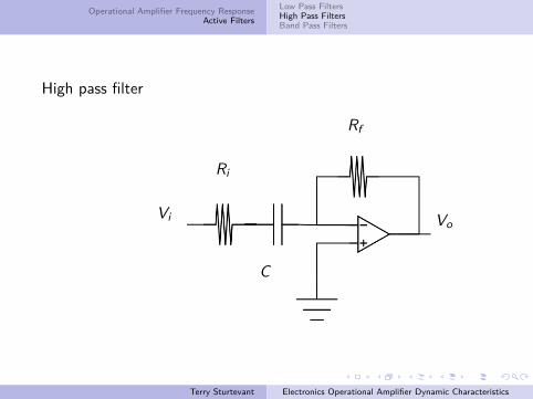
High pass filter
C
Ri
Vi
Rf
Vo
Terry Sturtevant Electronics Operational Amplifier Dynamic Characteristics

Operational Amplifier Frequency ResponseActive Filters
Low Pass FiltersHigh Pass FiltersBand Pass Filters
High pass filter at low frequencies
C
Ri
Vi
Rf
Vo
Terry Sturtevant Electronics Operational Amplifier Dynamic Characteristics
Operational Amplifier Frequency ResponseActive Filters
Low Pass FiltersHigh Pass FiltersBand Pass Filters
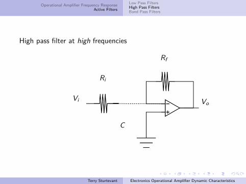
High pass filter at high frequencies
C
Ri
Vi
Rf
Vo
Terry Sturtevant Electronics Operational Amplifier Dynamic Characteristics

Operational Amplifier Frequency ResponseActive Filters
Low Pass FiltersHigh Pass FiltersBand Pass Filters
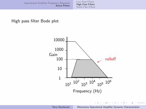
High pass filter Bode plot
1
10
100
1000
10000
Gain
101 102103 104
105 106
Frequency (Hz)
corner frequency
?
Terry Sturtevant Electronics Operational Amplifier Dynamic Characteristics

Operational Amplifier Frequency ResponseActive Filters
Low Pass FiltersHigh Pass FiltersBand Pass Filters
High pass filter Bode plot
1
10
100
1000
10000
Gain
101 102103 104
105 106
Frequency (Hz)
passband�
��
Terry Sturtevant Electronics Operational Amplifier Dynamic Characteristics
Operational Amplifier Frequency ResponseActive Filters
Low Pass FiltersHigh Pass FiltersBand Pass Filters
High pass filter Bode plot
1
10
100
1000
10000
Gain
101 102103 104
105 106
Frequency (Hz)
rolloff��
Terry Sturtevant Electronics Operational Amplifier Dynamic Characteristics
Operational Amplifier Frequency ResponseActive Filters
Low Pass FiltersHigh Pass FiltersBand Pass Filters
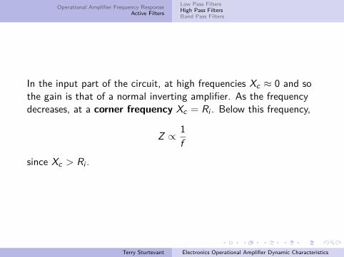
In the input part of the circuit, at high frequencies Xc ≈ 0 and sothe gain is that of a normal inverting amplifier. As the frequencydecreases, at a corner frequency Xc = Ri . Below this frequency,
Z ∝ 1f
since Xc > Ri .
Terry Sturtevant Electronics Operational Amplifier Dynamic Characteristics
Operational Amplifier Frequency ResponseActive Filters
Low Pass FiltersHigh Pass FiltersBand Pass Filters
A band pass filter combines a low pass and a high pass filter toallows frequencies between two corner frequencies, fc1 and fc2 topass, and attenuates those outside that range. The next figureshows the Bode plot for a band pass filter.
Terry Sturtevant Electronics Operational Amplifier Dynamic Characteristics
Operational Amplifier Frequency ResponseActive Filters
Low Pass FiltersHigh Pass FiltersBand Pass Filters
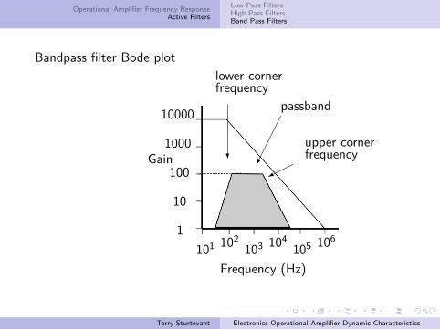
Bandpass filter Bode plot
1
10
100
1000
10000
Gain
101 102103 104
105 106
Frequency (Hz)
lower cornerfrequency
?
passband�����
upper cornerfrequency
���
Terry Sturtevant Electronics Operational Amplifier Dynamic Characteristics
Recommended