Electrical Machines and
Energy Conversion
Unit 4 Deck 1Transformer Principles

Construction of Power and Distribution Transformers
Construction• Core TypeHigh voltage• Shell TypeLess leakage flux
Type of Cooling• Ventilated Dry-Type TransformersThey are cooled by natural air convection.
• Gas-Filled Dry-Type TransformersCooled with nitrogen or other gases
• Liquid-Immersed TransformersHermetically sealed tanks with insulated
liquid (mineral oil, silicone oil)
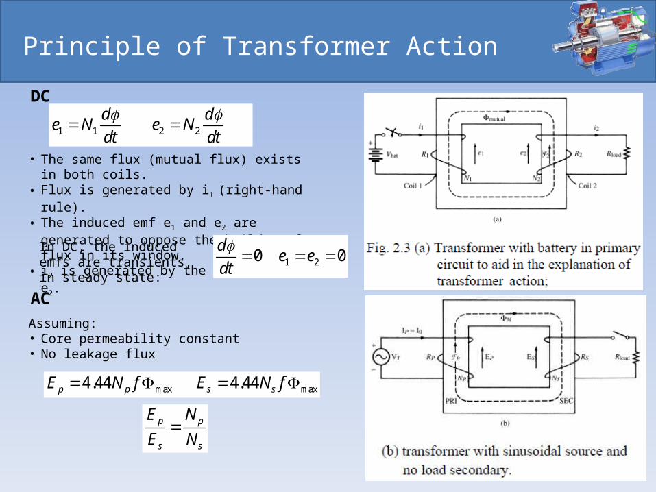
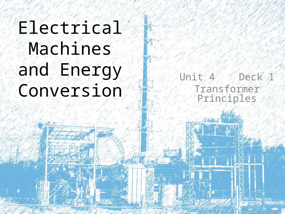
Principle of Transformer Action
1 1 2 2
d de N e N
dt dt
DC
• The same flux (mutual flux) exists in both coils.• Flux is generated by i1 (right-hand rule).• The induced emf e1 and e2 are generated to
oppose the buildup of flux in its window. • i2 is generated by the induced emf e2.
In DC, the induced emfs are transients, in steady state: 1 20 0
de e
dt
AC
Assuming:• Core permeability constant• No leakage flux
max max4.44 4.44p p s sE N f E N f
p p
s s
E N
E N
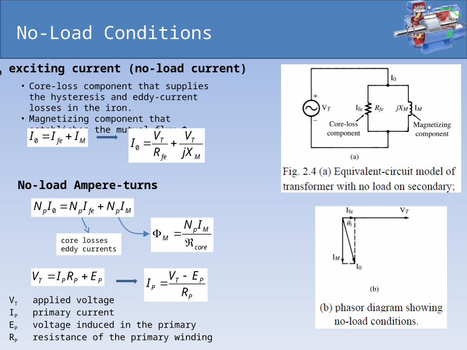
No-Load Conditions
• Core-loss component that supplies the hysteresis and eddy-current losses in the iron.
• Magnetizing component that establishes the mutual flux ΦM
0 fe MI I I 0
T T
fe M
V VI
R jX
I0 exciting current (no-load current)
No-load Ampere-turns
0p p fe p MN I N I N I
p MM
core
N I
core losseseddy currents
T P P PV I R E T PP
P
V EI
R
VT applied voltageIP primary currentEP voltage induced in the primaryRP resistance of the primary winding
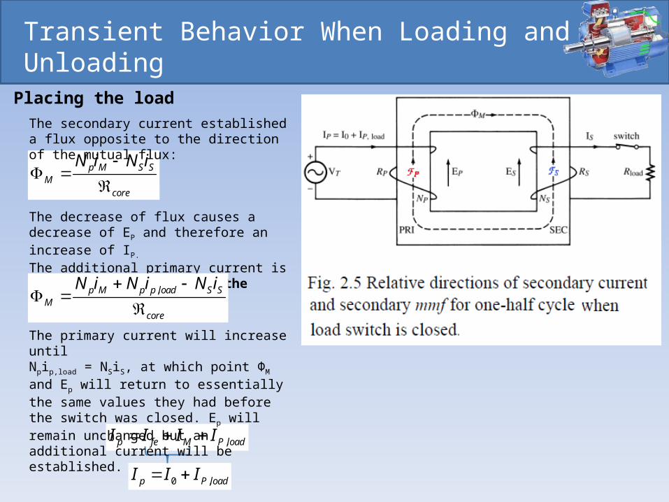
Transient Behavior When Loading and Unloading
Placing the load
p M S SM
core
N i N i
The secondary current established a flux opposite to the direction of the mutual flux:
The decrease of flux causes a decrease of EP and therefore an increase of IP.
The additional primary current is called load component of the primary current (IP,load).
,p M p p load S SM
core
N i N i N i
,p fe M P loadI I I I
0 ,p P loadI I I
The primary current will increase until Npip,load = NSiS, at which point ΦM and Ep will return to essentially the same values they had before the switch was closed. Ep will remain unchanged but an additional current will be established.
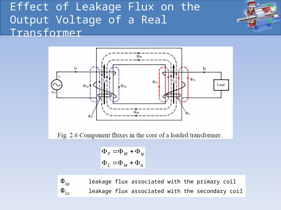
Effect of Leakage Flux on the Output Voltage of a Real Transformer
P M lp
S M ls
Φlp leakage flux associated with the primary coil
Φls leakage flux associated with the secondary coil
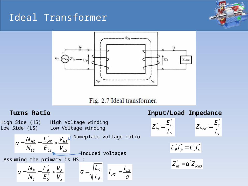
Ideal Transformer
'
'HS HS HS
LS LS LS
N E Va
N E V
Turns Ratio
High Side (HS) High Voltage windingLow Side (LS) Low Voltage winding
Assuming the primary is HS :'
'P P P
S S S
N E Va
N E V
Input/Load Impedance'
' Pin
P
EZ
I
Induced voltages
Nameplate voltage ratio
's
loads
EZ
I
' * ' *P p s sE I E I
' 2in loadZ a Z
LSHS
II
aS
P
La
L
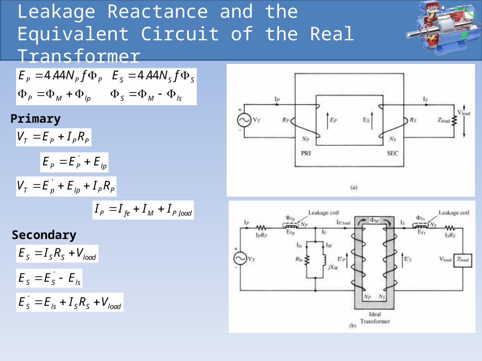
Leakage Reactance and the Equivalent Circuit of the Real Transformer
T P P PV E I R
'P P lpE E E
'T p lp P PV E E I R
,P fe M P loadI I I I
S S S loadE I R V
'S S lsE E E
'S ls S S loadE E I R V
Primary
Secondary
4.44 4.44P P P S S S
P M lp S M ls
E N f E N f
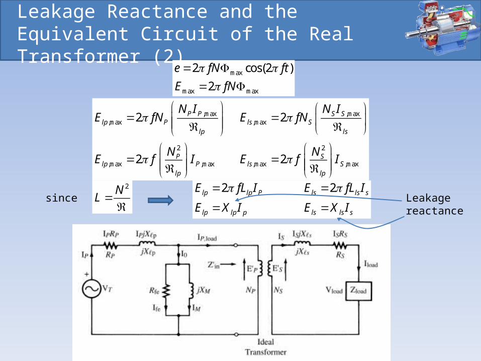
Leakage Reactance and the Equivalent Circuit of the Real Transformer (2)
,max ,max,max ,max
2 2
,max ,max ,max ,max
2 2
2 2
P P S Slp P ls S
lp ls
P Slp P ls S
lp lp
N I N IE fN E fN
N NE f I E f I
2N
L
2 2lp lp P ls ls s
lp lp p ls ls s
E fL I E fL I
E X I E X I
since Leakage
reactance
max
max max
2 cos(2 )
2
e fN ft
E fN
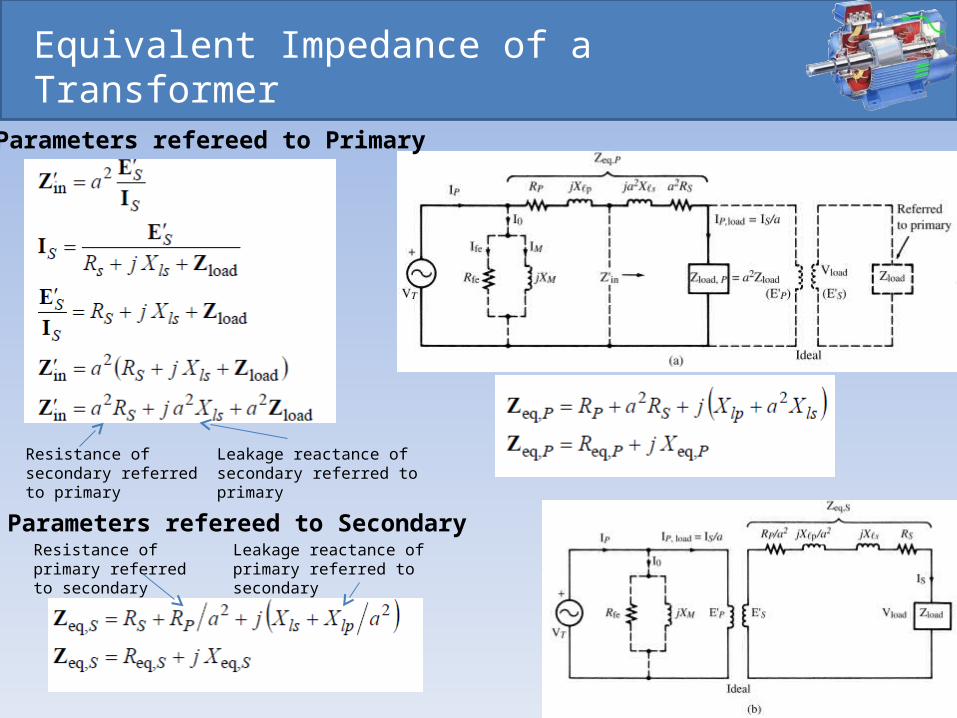
Equivalent Impedance of a Transformer
Parameters refereed to Primary
Parameters refereed to Secondary
Resistance of secondary referred to primary
Leakage reactance of secondary referred to primary
Resistance of primary referred to secondary
Leakage reactance of primary referred to secondary
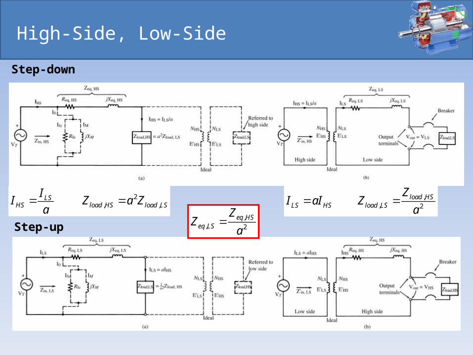
High-Side, Low-Side
2, ,
LSHS load HS load LS
II Z a Z
a ,
, 2load HS
LS HS load LS
ZI aI Z
a
Step-down
Step-up,
, 2
eq HSeq LS
ZZ
a
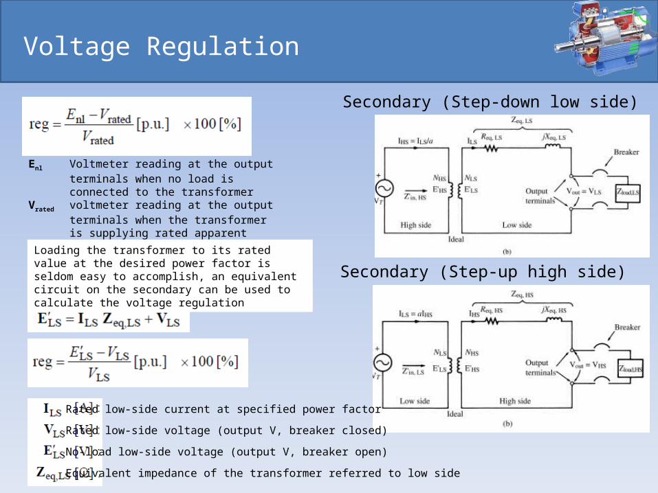
Voltage Regulation
Secondary (Step-down low side)
Secondary (Step-up high side)
Enl Voltmeter reading at the output terminals when no load is connected to the transformer
Vrated voltmeter reading at the output terminals when the transformer is supplying rated apparent power
Rated low-side current at specified power factor
Rated low-side voltage (output V, breaker closed)
No-load low-side voltage (output V, breaker open)
Equivalent impedance of the transformer referred to low side
Loading the transformer to its rated value at the desired power factor is seldom easy to accomplish, an equivalent circuit on the secondary can be used to calculate the voltage regulation
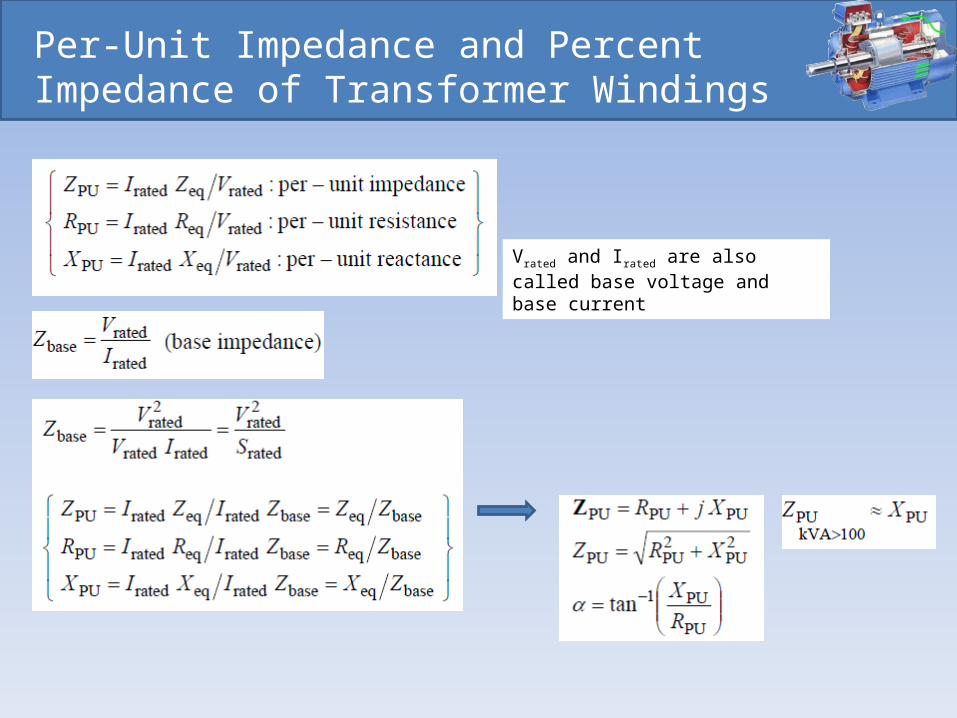
Per-Unit Impedance and Percent Impedance of Transformer Windings
Vrated and Irated are also called base voltage and base current
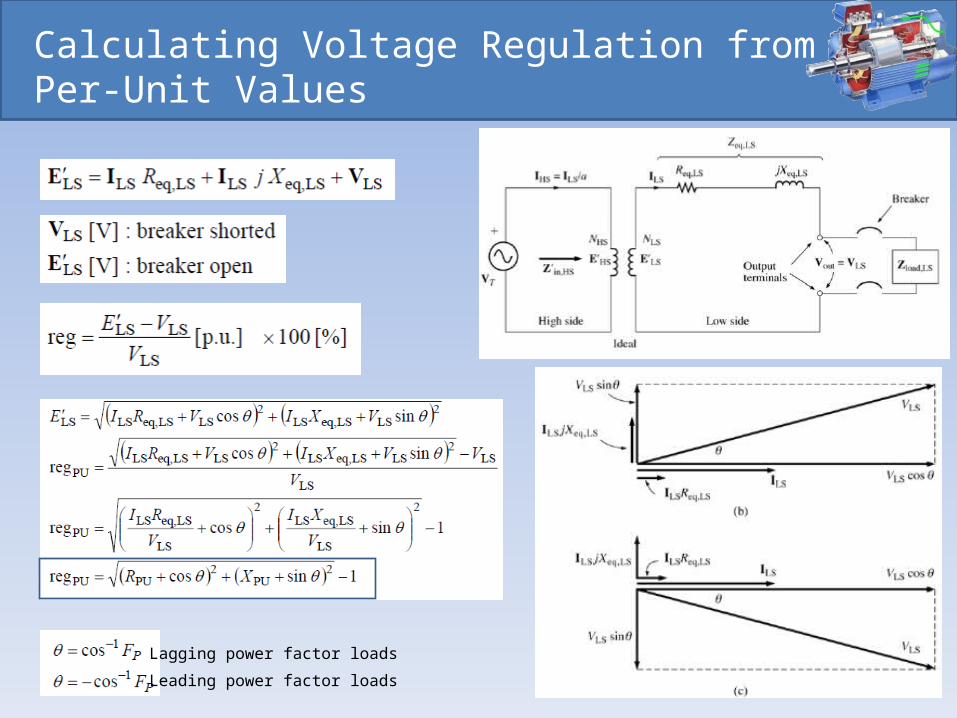
Calculating Voltage Regulation from Per-Unit Values
Lagging power factor loads
Leading power factor loads
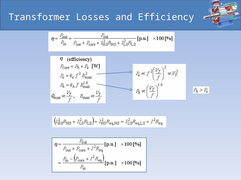
Transformer Losses and Efficiency
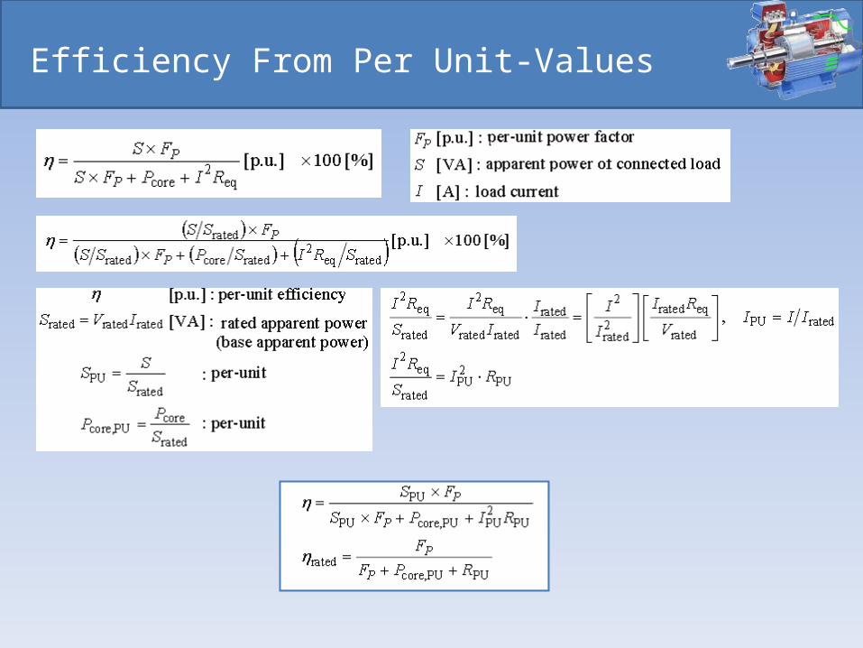
Efficiency From Per Unit-Values
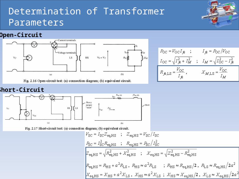
Determination of Transformer Parameters
Open-Circuit
Short-Circuit
Electrical Machines and Energy Conversion
End of Presentation
Recommended