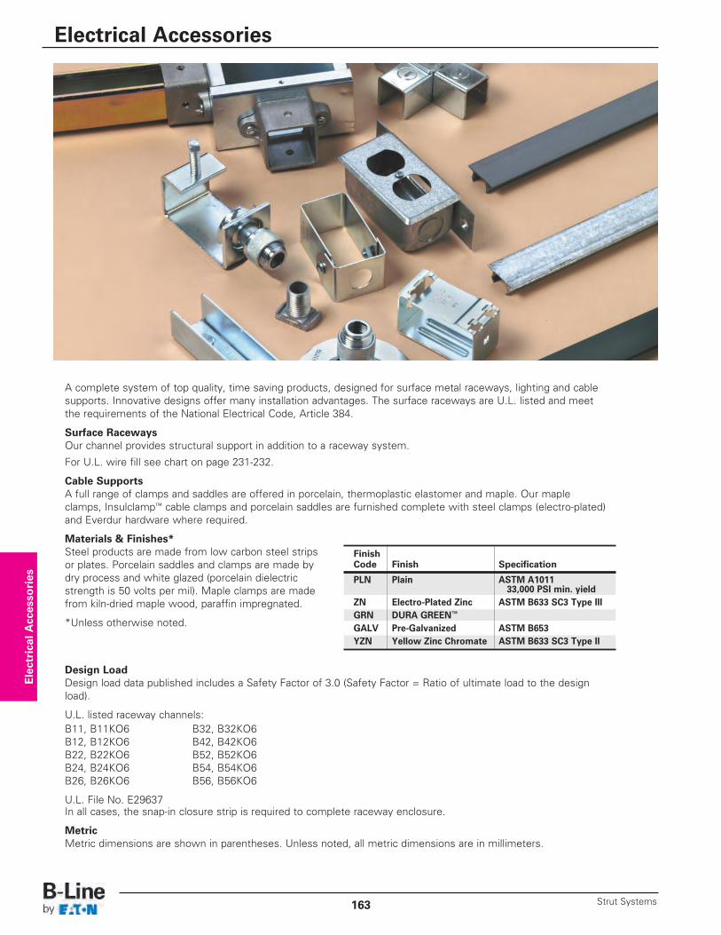
A complete system of top quality, time saving products, designed for surface metal raceways, lighting and cablesupports. Innovative designs offer many installation advantages. The surface raceways are U.L. listed and meetthe requirements of the National Electrical Code, Article 384.
Surface RacewaysOur channel provides structural support in addition to a raceway system.
For U.L. wire fill see chart on page 231-232.
Cable SupportsA full range of clamps and saddles are offered in porcelain, thermoplastic elastomer and maple. Our maple clamps, Insulclamp™ cable clamps and porcelain saddles are furnished complete with steel clamps (electro-plated)and Everdur hardware where required.
Materials & Finishes*Steel products are made from low carbon steel stripsor plates. Porcelain saddles and clamps are made by dry process and white glazed (porcelain dielectric strength is 50 volts per mil). Maple clamps are made from kiln-dried maple wood, paraffin impregnated.
*Unless otherwise noted.
Design LoadDesign load data published includes a Safety Factor of 3.0 (Safety Factor = Ratio of ultimate load to the designload).
U.L. listed raceway channels:B11, B11KO6 B32, B32KO6B12, B12KO6 B42, B42KO6B22, B22KO6 B52, B52KO6B24, B24KO6 B54, B54KO6B26, B26KO6 B56, B56KO6
U.L. File No. E29637In all cases, the snap-in closure strip is required to complete raceway enclosure.
MetricMetric dimensions are shown in parentheses. Unless noted, all metric dimensions are in millimeters.
Electrical Accessories
FinishCode Finish Specification
PLN Plain ASTM A101133,000 PSI min. yield
ZN Electro-Plated Zinc ASTM B633 SC3 Type IIIGRN DURA GREEN™
GALV Pre-Galvanized ASTM B653YZN Yellow Zinc Chromate ASTM B633 SC3 Type II
Electrical Accessories
Strut Systems163
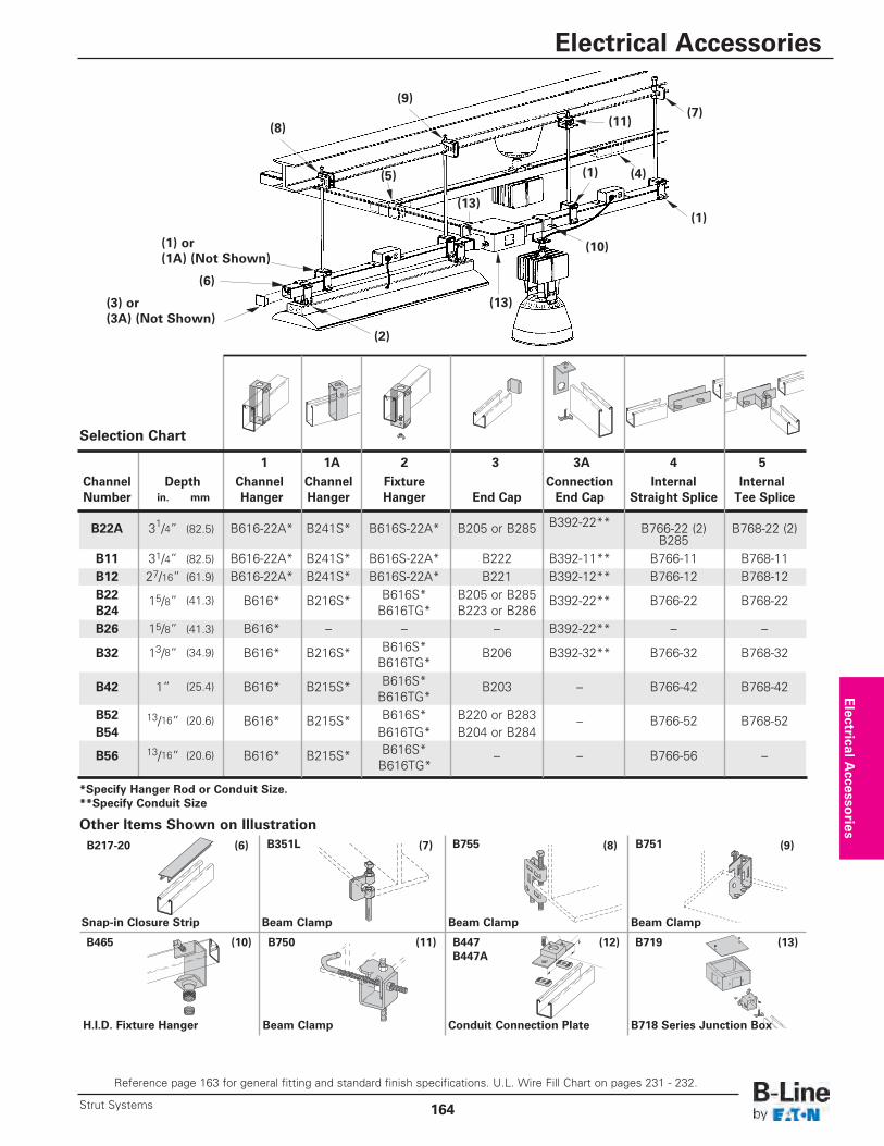
Channel Depth Channel Channel Fixture Connection Internal InternalNumber in. mm Hanger Hanger Hanger End Cap End Cap Straight Splice Tee Splice
B22A 31/4” (82.5) B616-22A* B241S* B616S-22A* B205 or B285 B392-22** B766-22 (2) B768-22 (2)B285
B11 31/4” (82.5) B616-22A* B241S* B616S-22A* B222 B392-11** B766-11 B768-11B12 27/16” (61.9) B616-22A* B241S* B616S-22A* B221 B392-12** B766-12 B768-12B22 15/8” (41.3) B616* B216S* B616S* B205 or B285 B392-22** B766-22 B768-22B24 B616TG* B223 or B286B26 15/8” (41.3) B616* – – – B392-22** – –
B32 13/8” (34.9) B616* B216S* B616S* B206 B392-32** B766-32 B768-32B616TG*
B42 1” (25.4) B616* B215S* B616S* B203 – B766-42 B768-42B616TG*
B52 13/16” (20.6) B616* B215S* B616S* B220 or B283 – B766-52 B768-52B54 B616TG* B204 or B284
B56 13/16” (20.6) B616* B215S* B616S* – – B766-56 –B616TG*
1 1A 2 3 3A 4 5
*Specify Hanger Rod or Conduit Size.**Specify Conduit Size
Other Items Shown on Illustration
Selection Chart
Snap-in Closure Strip
H.I.D. Fixture Hanger Beam Clamp Conduit Connection Plate B718 Series Junction Box
Beam Clamp Beam Clamp Beam Clamp
B217-20 (6) (7) (8) (9)
(10) (11) (12) (13)B465
B351L B755 B751
B719B447B447A
B750
(8)
(9)
(5)
(2)
(13)
(13)
(10)
(1)
(1) (4)
(7)(11)
(1) or(1A) (Not Shown)
(3) or(3A) (Not Shown)
(6)
Electrical A
ccessories
Reference page 163 for general fitting and standard finish specifications. U.L. Wire Fill Chart on pages 231 - 232.
Electrical Accessories
164Strut Systems
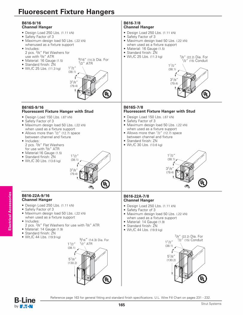
B616-7/8Channel Hanger• Design Load 250 Lbs. (1.11 kN)• Safety Factor of 3• Maximum design load 50 Lbs. (.22 kN)when used as a fixture support
• Material: 16 Gauge (1.5)• Standard finish: ZN• Wt./C 25 Lbs. (11.3 kg)
B616-9/16Channel Hanger• Design Load 250 Lbs. (1.11 kN)• Safety Factor of 3• Maximum design load 50 Lbs. (.22 kN)whenused as a fixture support
• Includes:2 pcs. 3/8” Flat Washers foruse with 3/8” ATR
• Material: 16 Gauge (1.5)• Standard finish: ZN• Wt./C 25 Lbs. (11.3 kg)
B616S-9/16Fluorescent Fixture Hanger with Stud • Design Load 150 Lbs. (.67 kN)• Safety Factor of 3• Maximum design load 50 Lbs. (.22 kN)when used as a fixture support
• Allows more than 1/2” (12.7) space between channel and fixture
• Includes:2 pcs. 3/8” Flat Washers for use with 3/8” ATR
• Material:16 Gauge (1.5)• Standard finish: ZN• Wt./C 30 Lbs. (13.6 kg)
B616S-7/8Fluorescent Fixture Hanger with Stud • Design Load 150 Lbs. (.67 kN)• Safety Factor of 3• Maximum design load 50 Lbs. (.22 kN)when used as a fixture support
• Allows more than 1/2” (12.7) space between channel and fixture
• Standard finish: ZN• Wt./C 30 Lbs. (13.6 kg)
B616-22A-9/16 Channel Hanger• Design Load 250 Lbs. (1.11 kN)• Safety Factor of 3• Maximum design load 50 Lbs. (.22 kN)when used as a fixture support
• Includes:2 pcs. 3/8” Flat Washers for use with 3/8” ATR
• Material: 14 Gauge (1.9)• Standard finish: ZN• Wt./C 44 Lbs. (19.9 kg)
B616-22A-7/8Channel Hanger• Design Load 250 Lbs. (1.11 kN)• Safety Factor of 3• Maximum design load 50 Lbs. (.22 kN)when used as a fixture support
• Material: 14 Gauge (1.9)• Standard finish: ZN• Wt./C 44 Lbs. (19.9 kg)
31/8” (79.4)
11/2” (38.1)
9/16” (14.3) Dia. For1/2” ATR
7/8” (22.2) Dia. For1/2” (15) Conduit
31/8” (79.4)
11/2” (38.1)
31/8” (79.4)
11/2” (38.1)
31/8” (79.4)
11/2” (38.1)
51/8” (130.2)
11/2” (38.1)
9/16” (14.3) Dia. For1/2” ATR
7/8” (22.2) Dia. For1/2” (15) Conduit11/2”
(38.1)
51/8” (130.2)
Electrical Accessories
Reference page 163 for general fitting and standard finish specifications. U.L. Wire Fill Chart on pages 231 - 232.
Fluorescent Fixture Hangers
Strut Systems165
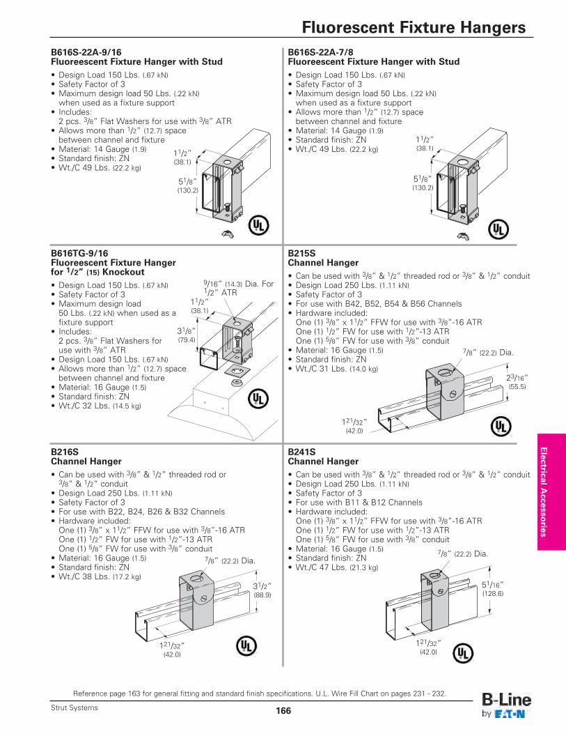
B616S-22A-7/8Fluoreescent Fixture Hanger with Stud• Design Load 150 Lbs. (.67 kN)• Safety Factor of 3• Maximum design load 50 Lbs. (.22 kN)when used as a fixture support
• Allows more than 1/2” (12.7) space between channel and fixture
• Material: 14 Gauge (1.9)• Standard finish: ZN• Wt./C 49 Lbs. (22.2 kg)
B616S-22A-9/16 Fluoreescent Fixture Hanger with Stud• Design Load 150 Lbs. (.67 kN)• Safety Factor of 3• Maximum design load 50 Lbs. (.22 kN)when used as a fixture support
• Includes:2 pcs. 3/8” Flat Washers for use with 3/8” ATR
• Allows more than 1/2” (12.7) space between channel and fixture
• Material: 14 Gauge (1.9)• Standard finish: ZN• Wt./C 49 Lbs. (22.2 kg)
B616TG-9/16 Fluoreescent Fixture Hanger for 1/2” (15) Knockout• Design Load 150 Lbs. (.67 kN)• Safety Factor of 3• Maximum design load50 Lbs. (.22 kN) when used as afixture support
• Includes:2 pcs. 3/8” Flat Washers for use with 3/8” ATR
• Design Load 150 Lbs. (.67 kN)• Allows more than 1/2” (12.7) space between channel and fixture
• Material: 16 Gauge (1.5)• Standard finish: ZN• Wt./C 32 Lbs. (14.5 kg)
B215SChannel Hanger• Can be used with 3/8” & 1/2” threaded rod or 3/8” & 1/2” conduit• Design Load 250 Lbs. (1.11 kN)• Safety Factor of 3• For use with B42, B52, B54 & B56 Channels• Hardware included:One (1) 3/8” x 11/2” FFW for use with 3/8”-16 ATROne (1) 1/2” FW for use with 1/2”-13 ATROne (1) 5/8” FW for use with 3/8” conduit
• Material: 16 Gauge (1.5)• Standard finish: ZN• Wt./C 31 Lbs. (14.0 kg)
B216SChannel Hanger• Can be used with 3/8” & 1/2” threaded rod or3/8” & 1/2” conduit
• Design Load 250 Lbs. (1.11 kN)• Safety Factor of 3• For use with B22, B24, B26 & B32 Channels• Hardware included:One (1) 3/8” x 11/2” FFW for use with 3/8”-16 ATROne (1) 1/2” FW for use with 1/2”-13 ATROne (1) 5/8” FW for use with 3/8” conduit
• Material: 16 Gauge (1.5)• Standard finish: ZN• Wt./C 38 Lbs. (17.2 kg)
B241SChannel Hanger• Can be used with 3/8” & 1/2” threaded rod or 3/8” & 1/2” conduit• Design Load 250 Lbs. (1.11 kN)• Safety Factor of 3• For use with B11 & B12 Channels• Hardware included:One (1) 3/8” x 11/2” FFW for use with 3/8”-16 ATROne (1) 1/2” FW for use with 1/2”-13 ATROne (1) 5/8” FW for use with 3/8” conduit
• Material: 16 Gauge (1.5)• Standard finish: ZN• Wt./C 47 Lbs. (21.3 kg)
51/8” (130.2)
11/2” (38.1)
51/8” (130.2)
11/2” (38.1)
31/8” (79.4)
11/2” (38.1)
9/16” (14.3) Dia. For1/2” ATR
7/8” (22.2) Dia.
23/16” (55.5)
31/2” (88.9)
121/32” (42.0)
7/8” (22.2) Dia.7/8” (22.2) Dia.
121/32” (42.0)
51/16” (128.6)
121/32” (42.0)
Electrical A
ccessories
Reference page 163 for general fitting and standard finish specifications. U.L. Wire Fill Chart on pages 231 - 232.
Fluorescent Fixture Hangers
166Strut Systems
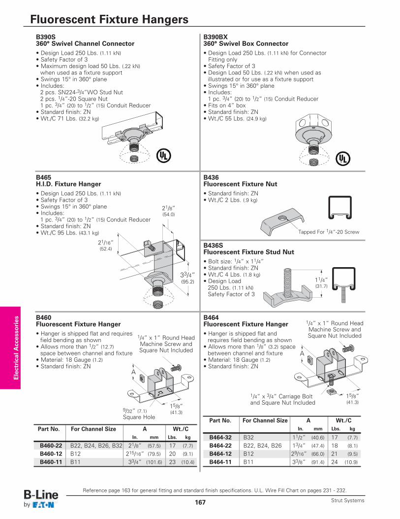
B390BX 360° Swivel Box Connector• Design Load 250 Lbs. (1.11 kN) for Connector Fitting only
• Safety Factor of 3• Design Load 50 Lbs. (.22 kN) when used as illustrated or for use as a fixture support
• Swings 15° in 360° plane• Includes:1 pc. 3/4” (20) to 1/2” (15) Conduit Reducer
• Fits on 4” box• Standard finish: ZN• Wt./C 55 Lbs. (24.9 kg)
B390S 360° Swivel Channel Connector• Design Load 250 Lbs. (1.11 kN)• Safety Factor of 3• Maximum design load 50 Lbs. (.22 kN)when used as a fixture support
• Swings 15° in 360° plane• Includes:2 pcs. SN224-3/4”WO Stud Nut2 pcs. 1/4”-20 Square Nut1 pc. 3/4” (20) to 1/2” (15) Conduit Reducer
• Standard finish: ZN• Wt./C 71 Lbs. (32.2 kg)
B465 H.I.D. Fixture Hanger• Design Load 250 Lbs. (1.11 kN)• Safety Factor of 3• Swings 15° in 360° plane• Includes:1 pc. 3/4” (20) to 1/2” (15) Conduit Reducer
• Standard finish: ZN• Wt./C 95 Lbs. (43.1 kg)
B436S Fluorescent Fixture Stud Nut• Bolt size: 1/4” x 11/4”• Standard finish: ZN• Wt./C 4 Lbs. (1.8 kg)• Design Load250 Lbs. (1.11 kN)Safety Factor of 3
B436 Fluorescent Fixture Nut• Standard finish: ZN• Wt./C 2 Lbs. (.9 kg)
B460 Fluorescent Fixture Hanger• Hanger is shipped flat and requires field bending as shown
• Allows more than 1/2” (12.7)space between channel and fixture
• Material: 18 Gauge (1.2)• Standard finish: ZN
B464 Fluorescent Fixture Hanger• Hanger is shipped flat and requires field bending as shown
• Allows more than 1/8” (3.2) space between channel and fixture
• Material: 18 Gauge (1.2)• Standard finish: ZN
33/4”(95.2)
21/16” (52.4)
15/8” (41.3)9/32” (7.1)
Square Hole
Part No. For Channel Size A Wt./CIn. mm Lbs. kg
B460-22 B22, B24, B26, B32 21/8” (57.5) 17 (7.7)
B460-12 B12 215/16” (79.5) 20 (9.1)
B460-11 B11 33/4” (101.6) 23 (10.4)
A
Tapped For 1/4”-20 Screw
11/4” (31.7)
Part No. For Channel Size A Wt./CIn. mm Lbs. kg
B464-32 B32 11/2” (40.6) 17 (7.7)
B464-22 B22, B24, B26 13/4” (47.4) 18 (8.1)
B464-12 B12 29/16” (66.0) 21 (9.5)
B464-11 B11 33/8” (91.4) 24 (10.9)
A
1/4” x 1” Round Head Machine Screw and Square Nut Included1/4” x 1” Round Head
Machine Screw and Square Nut Included
1/4” x 3/4” Carriage Boltand Square Nut Included
15/8” (41.3)
21/8” (54.0)
Electrical Accessories
Reference page 163 for general fitting and standard finish specifications. U.L. Wire Fill Chart on pages 231 - 232.
Fluorescent Fixture Hangers
Strut Systems167
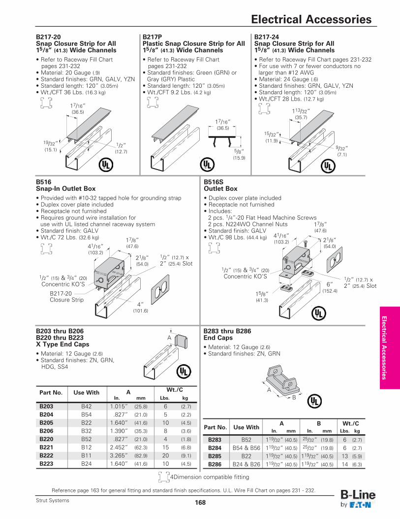
B516S Outlet Box• Duplex cover plate included• Receptacle not furnished• Includes:2 pcs. 1/4”-20 Flat Head Machine Screws2 pcs. N224WO Channel Nuts
• Standard finish: GALV• Wt./C 98 Lbs. (44.4 kg)
B516 Snap-In Outlet Box• Provided with #10-32 tapped hole for grounding strap• Duplex cover plate included• Receptacle not furnished• Requires ground wire installation for use with UL listed channel raceway system
• Standard finish: GALV• Wt./C 72 Lbs. (32.6 kg)
B203 thru B206B220 thru B223X Type End Caps• Material: 12 Gauge (2.6)• Standard finishes: ZN, GRN,HDG, SS4
B283 thru B286 End Caps• Material: 12 Gauge (2.6)• Standard finishes: ZN, GRN
B217-20 Snap Closure Strip for All 15/8” (41.3) Wide Channels• Refer to Raceway Fill Chartpages 231-232
• Material: 20 Gauge (.9)• Standard finishes: GRN, GALV, YZN• Standard length: 120” (3.05m)• Wt./CFT 36 Lbs. (16.3 kg)
B217P Plastic Snap Closure Strip for All 15/8” (41.3) Wide Channels• Refer to Raceway Fill Chartpages 231-232
• Standard finishes: Green (GRN) or Gray (GRY) Plastic
• Standard length: 120” (3.05m)• Wt./CFT 9.2 Lbs. (4.2 kg)
B217-24 Snap Closure Strip for All 15/8” (41.3) Wide Channels• Refer to Raceway Fill Chart pages 231-232• For use with 7 or fewer conductors no larger than #12 AWG
• Material: 24 Gauge (.6)• Standard finishes: GRN, GALV, YZN• Standard length: 120” (3.05m)• Wt./CFT 28 Lbs. (12.7 kg)
17/8” (47.6)
21/8” (54.0)
41/16” (103.2)
4” (101.6)
1/2” (12.7) x2” (25.4) Slot
B217-20 Closure Strip
1/2” (15) & 3/4” (20)Concentric KO’S
A Wt./CPart No. Use WithIn. mm Lbs. kg
B203 B42 1.015” (25.8) 6 (2.7)
B204 B54 .827” (21.0) 5 (2.2)
B205 B22 1.640” (41.6) 10 (4.5)
B206 B32 1.390” (35.3) 8 (3.6)
B220 B52 .827” (21.0) 4 (1.8)
B221 B12 2.452” (62.3) 15 (6.8)
B222 B11 3.265” (82.9) 20 (9.1)
B223 B24 1.640” (41.6) 10 (4.5)
A
A B Wt./CPart No. Use With
In. mm In. mm Lbs. kg
B283 B52 119/32” (40.5) 25/32” (19.8) 6 (2.7)
B284 B54 & B56 119/32” (40.5) 25/32” (19.8) 6 (2.7)
B285 B22 119/32” (40.5) 119/32” (40.5) 13 (5.9)
B286 B24 & B26 119/32” (40.5) 119/32” (40.5) 14 (6.3)
1/2” (12.7) x2” (25.4) Slot
1/2” (15) & 3/4” (20)Concentric KO’S
17/8” (47.6)
15/8” (41.3)
21/8” (54.0)
41/16” (103.2)
6”(152.4)
AB
17/16” (36.5)
19/32” (15.1)
1/2” (12.7)
113/32” (35.7)
15/32” (11.9)
9/32” (7.1)
17/16” (36.5)
5/8” (15.9)
Electrical A
ccessories
Reference page 163 for general fitting and standard finish specifications. U.L. Wire Fill Chart on pages 231 - 232.
Electrical Accessories
168Strut Systems
4Dimension compatible fitting
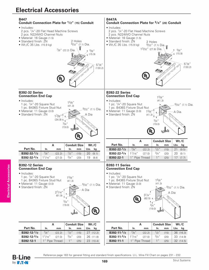
B447A Conduit Connection Plate for 3/4” (20) Conduit• Includes:2 pcs. 1/4”-20 Flat Head Machine Screws2 pcs. N224WO Channel Nuts
• Material: 16 Gauge (1.5)• Standard finish: ZN• Wt./C 35 Lbs. (15.9 kg)
B447 Conduit Connection Plate for 1/2” (15) Conduit• Includes:2 pcs. 1/4”-20 Flat Head Machine Screws2 pcs. N224WO Channel Nuts
• Material: 16 Gauge (1.5)• Standard finish: ZN• Wt./C 35 Lbs. (15.9 kg)
B392-32 Series Connection End Cap• Includes:1 pc. 1/4”-20 Square Nut1 pc. B436S Fixture Stud Nut
• Material: 11 Gauge (3.0)• Standard finish: ZN
B392-22 Series Connection End Cap• Includes:1 pc. 1/4”-20 Square Nut1 pc. B436S Fixture Stud Nut
• Material: 11 Gauge (3.0)• Standard finish: ZN
B392-12 Series Connection End Cap• Includes:1 pc. 1/4”-20 Square Nut1 pc. B436S Fixture Stud Nut
• Material: 11 Gauge (3.0)• Standard finish: ZN
B392-11 Series Connection End Cap• Includes:1 pc. 1/4”-20 Square Nut1 pc. B436S Fixture Stud Nut
• Material: 11 Gauge (3.0)• Standard finish: ZN
7/8” (22.2) Dia.
2 Holes 9/32” (7.1) Dia.
2 Holes 9/32” (7.1) Dia.
5/8” (15.9)
15/8” (41.3)
13/8”(34.9)
3/4” (19.0)
A Dia
9/32” (7.1) Dia.
15/8” (41.3)
27/16” (61.9)
3/4” (19.0)
A Dia
9/32” (7.1) Dia.
13/32” (27.8) Dia. 5/8” (15.9)
51/8” (130.2)
A Conduit SIze Wt./CPart No. In. mm In. mm Lbs. kg
B392-22-1/2 7/8” (22.2) 1/2” (15) 21 (9.5)B392-22-3/4 11/16” (27.0) 3/4” (20) 20 (9.1)B392-22-1 1” Pipe Thread 1” (25) 17 (7.7)
15/8” (41.3)
15/8” (41.3)
3/4” (19.0)
A Dia.
9/32” (7.1) Dia.
15/8” (41.3)
31/4” (82.5)
3/4” (19.0)
A Dia
9/32” (7.1) Dia.
51/8” (130.2)
Electrical Accessories
Reference page 163 for general fitting and standard finish specifications. U.L. Wire Fill Chart on pages 231 - 232.
Electrical Accessories
Strut Systems169
A Conduit SIze Wt./CPart No. In. mm In. mm Lbs. kg
B392-11-1/2 7/8” (22.2) 1/2” (15) 36 (16.3)B392-11-3/4 11/16” (27.0) 3/4” (20) 33 (14.9)B392-11-1 1” Pipe Thread 1” (25) 32 (14.5)
A Conduit SIze Wt./CPart No. In. mm In. mm Lbs. kg
B392-12-1/2 7/8” (22.2) 1/2” (15) 27 (12.2)B392-12-3/4 11/16” (27.0) 3/4” (20) 26 (11.8)B392-12-1 1” Pipe Thread 1” (25) 23 (10.4)
A Conduit SIze Wt./CPart No. In. mm In. mm Lbs. kg
B392-32-1/2 7/8” (22.2) 1/2” (15) 20 (9.1)B392-32-3/4 11/16” (27.0) 3/4” (20) 19 (8.6
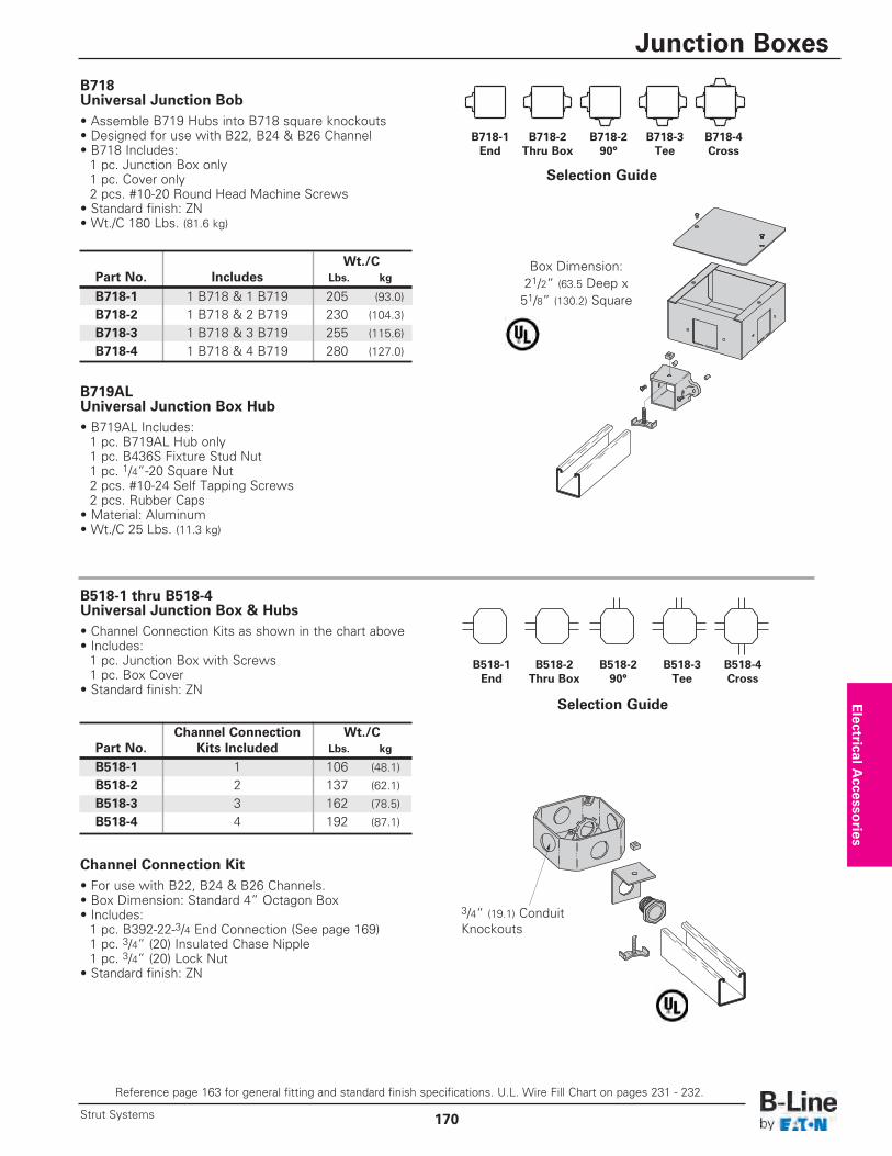
Wt./CPart No. Includes Lbs. kg
B718-1 1 B718 & 1 B719 205 (93.0)
B718-2 1 B718 & 2 B719 230 (104.3)
B718-3 1 B718 & 3 B719 255 (115.6)
B718-4 1 B718 & 4 B719 280 (127.0)
Channel Connection Kit• For use with B22, B24 & B26 Channels.• Box Dimension: Standard 4” Octagon Box• Includes:1 pc. B392-22-3/4 End Connection (See page 169)1 pc. 3/4” (20) Insulated Chase Nipple1 pc. 3/4” (20) Lock Nut
• Standard finish: ZN
Box Dimension:21/2” (63.5 Deep x51/8” (130.2) Square
B718 Universal Junction Bob • Assemble B719 Hubs into B718 square knockouts• Designed for use with B22, B24 & B26 Channel• B718 Includes:1 pc. Junction Box only1 pc. Cover only2 pcs. #10-20 Round Head Machine Screws
• Standard finish: ZN• Wt./C 180 Lbs. (81.6 kg)
B719AL Universal Junction Box Hub• B719AL Includes:1 pc. B719AL Hub only1 pc. B436S Fixture Stud Nut1 pc. 1/4”-20 Square Nut2 pcs. #10-24 Self Tapping Screws2 pcs. Rubber Caps
• Material: Aluminum• Wt./C 25 Lbs. (11.3 kg)
B518-1 thru B518-4 Universal Junction Box & Hubs• Channel Connection Kits as shown in the chart above• Includes:1 pc. Junction Box with Screws1 pc. Box Cover
• Standard finish: ZN
B718-1End
B718-290°
B718-3Tee
B718-4Cross
B718-2Thru Box
Channel Connection Wt./CPart No. Kits Included Lbs. kg
B518-1 1 106 (48.1)
B518-2 2 137 (62.1)
B518-3 3 162 (78.5)
B518-4 4 192 (87.1)
Selection Guide
Selection Guide
B518-1End
B518-290°
B518-3Tee
B518-4Cross
B518-2Thru Box
3/4” (19.1) Conduit Knockouts
Electrical A
ccessories
Reference page 163 for general fitting and standard finish specifications. U.L. Wire Fill Chart on pages 231 - 232.
Junction Boxes
170Strut Systems
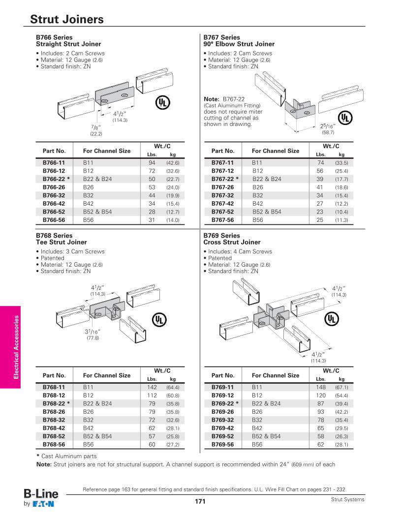
B766 Series Straight Strut Joiner• Includes: 2 Cam Screws• Material: 12 Gauge (2.6)• Standard finish: ZN
B768 Series Tee Strut Joiner• Includes: 3 Cam Screws• Patented• Material: 12 Gauge (2.6)• Standard finish: ZN
B769 Series Cross Strut Joiner• Includes: 4 Cam Screws• Patented• Material: 12 Gauge (2.6)• Standard finish: ZN
B767 Series 90° Elbow Strut Joiner• Includes: 2 Cam Screws• Material: 12 Gauge (2.6)• Standard finish: ZN
41/2” (114.3)
7/8” (22.2)
41/2” (114.3)
31/16” (77.8)
25/16” (58.7)
Wt./CPart No. For Channel Size
Lbs. kg
B766-11 B11 94 (42.6)
B766-12 B12 72 (32.6)
B766-22 * B22 & B24 50 (22.7)
B766-26 B26 53 (24.0)
B766-32 B32 44 (19.9)
B766-42 B42 34 (15.4)
B766-52 B52 & B54 28 (12.7)
B766-56 B56 31 (14.0)
41/2” (114.3)
41/2” (114.3)
Note: B767-22 (Cast Aluminum Fitting)does not require mitercutting of channel asshown in drawing.
Electrical Accessories
Reference page 163 for general fitting and standard finish specifications. U.L. Wire Fill Chart on pages 231 - 232.
Strut Joiners
Strut Systems171
Wt./CPart No. For Channel Size
Lbs. kg
B767-11 B11 74 (33.5)
B767-12 B12 56 (25.4)
B767-22 * B22 & B24 39 (17.7)
B767-26 B26 41 (18.6)
B767-32 B32 34 (15.4)
B767-42 B42 27 (12.2)
B767-52 B52 & B54 23 (10.4)
B767-56 B56 25 (11.3)
Wt./CPart No. For Channel Size
Lbs. kg
B769-11 B11 148 (67.1)
B769-12 B12 120 (54.4)
B769-22 * B22 & B24 87 (39.4)
B769-26 B26 93 (42.2)
B769-32 B32 78 (35.4)
B769-42 B42 65 (29.5)
B769-52 B52 & B54 58 (26.3)
B769-56 B56 62 (28.1)
Wt./CPart No. For Channel Size
Lbs. kg
B768-11 B11 142 (64.4)
B768-12 B12 112 (50.8)
B768-22 * B22 & B24 79 (35.8)
B768-26 B26 79 (35.8)
B768-32 B32 72 (32.6)
B768-42 B42 62 (28.1)
B768-52 B52 & B54 57 (25.8)
B768-56 B56 60 (27.2)
* Cast Aluminum partsNote: Strut joiners are not for structural support. A channel support is recommended within 24” (609 mm) of each
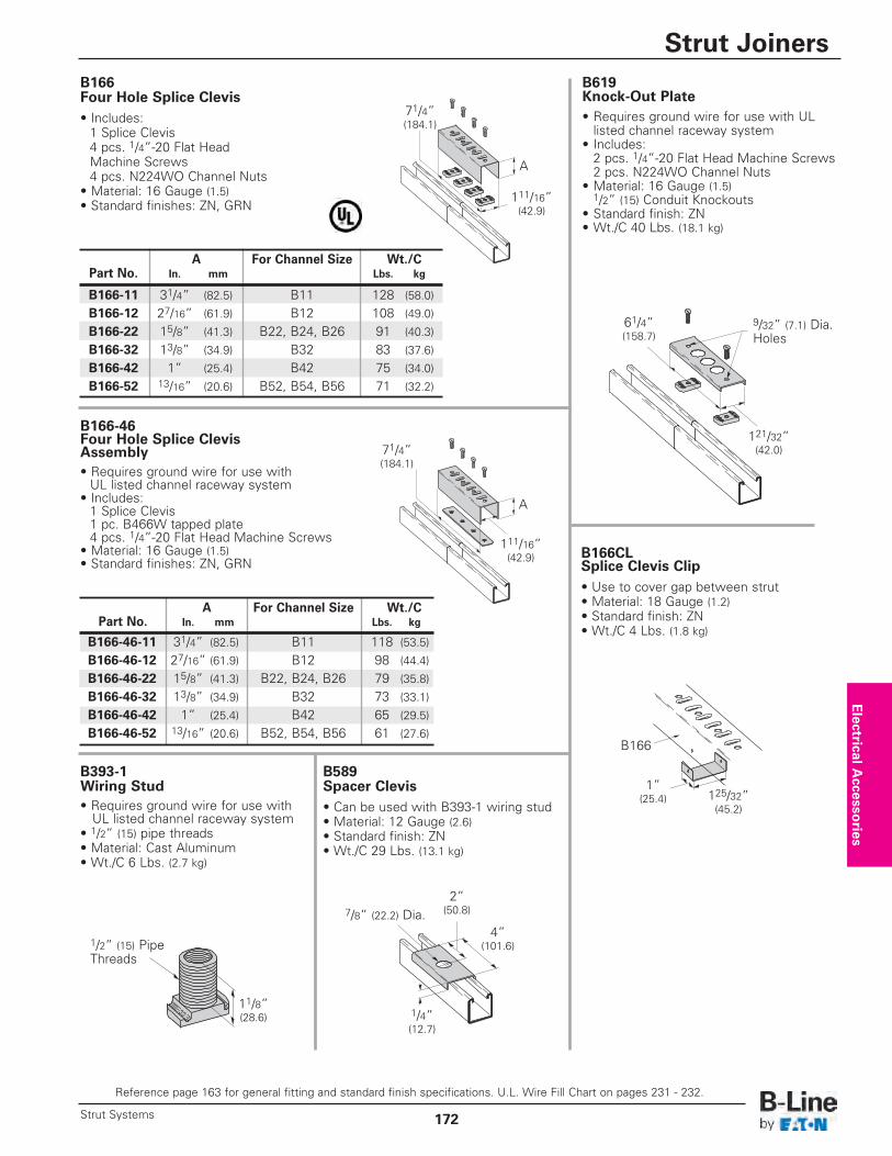
B166-46 Four Hole Splice ClevisAssembly• Requires ground wire for use withUL listed channel raceway system
• Includes:1 Splice Clevis1 pc. B466W tapped plate4 pcs. 1/4”-20 Flat Head Machine Screws
• Material: 16 Gauge (1.5)• Standard finishes: ZN, GRN
B166 Four Hole Splice Clevis • Includes:1 Splice Clevis4 pcs. 1/4”-20 Flat Head Machine Screws4 pcs. N224WO Channel Nuts
• Material: 16 Gauge (1.5)• Standard finishes: ZN, GRN
A For Channel Size Wt./CPart No. In. mm Lbs. kg
B166-11 31/4” (82.5) B11 128 (58.0)
B166-12 27/16” (61.9) B12 108 (49.0)
B166-22 15/8” (41.3) B22, B24, B26 91 (40.3)
B166-32 13/8” (34.9) B32 83 (37.6)
B166-42 1” (25.4) B42 75 (34.0)
B166-52 13/16” (20.6) B52, B54, B56 71 (32.2)
A
111/16” (42.9)
71/4” (184.1)
A For Channel Size Wt./CPart No. In. mm Lbs. kg
B166-46-11 31/4” (82.5) B11 118 (53.5)
B166-46-12 27/16” (61.9) B12 98 (44.4)
B166-46-22 15/8” (41.3) B22, B24, B26 79 (35.8)
B166-46-32 13/8” (34.9) B32 73 (33.1)
B166-46-42 1” (25.4) B42 65 (29.5)
B166-46-52 13/16” (20.6) B52, B54, B56 61 (27.6)
A
71/4” (184.1)
111/16” (42.9) B166CL
Splice Clevis Clip• Use to cover gap between strut• Material: 18 Gauge (1.2)• Standard finish: ZN• Wt./C 4 Lbs. (1.8 kg)
B619 Knock-Out Plate• Requires ground wire for use with UL listed channel raceway system
• Includes:2 pcs. 1/4”-20 Flat Head Machine Screws2 pcs. N224WO Channel Nuts
• Material: 16 Gauge (1.5)1/2” (15) Conduit Knockouts
• Standard finish: ZN• Wt./C 40 Lbs. (18.1 kg)
B393-1 Wiring Stud• Requires ground wire for use with UL listed channel raceway system
• 1/2” (15) pipe threads• Material: Cast Aluminum• Wt./C 6 Lbs. (2.7 kg)
B589 Spacer Clevis• Can be used with B393-1 wiring stud• Material: 12 Gauge (2.6)• Standard finish: ZN• Wt./C 29 Lbs. (13.1 kg)
125/32” (45.2)
1” (25.4)
B166
9/32” (7.1) Dia.Holes
121/32” (42.0)
61/4” (158.7)
11/8” (28.6)
1/2” (15) PipeThreads
7/8” (22.2) Dia.
1/4” (12.7)
4” (101.6)
2” (50.8)
Electrical A
ccessories
Reference page 163 for general fitting and standard finish specifications. U.L. Wire Fill Chart on pages 231 - 232.
Strut Joiners
172Strut Systems
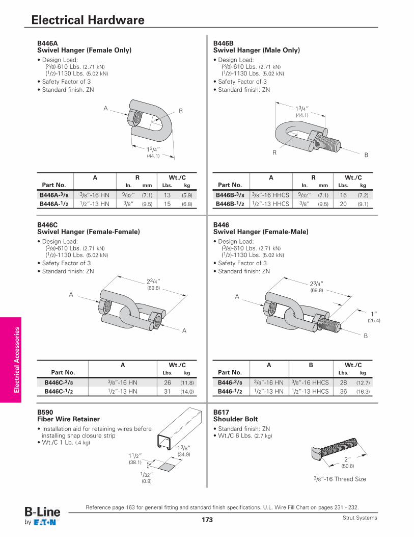
B590 Fiber Wire Retainer• Installation aid for retaining wires before installing snap closure strip
• Wt./C 1 Lb. (.4 kg)
B617 Shoulder Bolt• Standard finish: ZN• Wt./C 6 Lbs. (2.7 kg)
13/8” (34.9)11/2”
(38.1)
1/32” (0.8)
3/8”-16 Thread Size
2” (50.8)
Electrical Accessories
B446A Swivel Hanger (Female Only)• Design Load:
(3/8)-610 Lbs. (2.71 kN)(1/2)-1130 Lbs. (5.02 kN)
• Safety Factor of 3• Standard finish: ZN
B446B Swivel Hanger (Male Only)• Design Load:
(3/8)-610 Lbs. (2.71 kN)(1/2)-1130 Lbs. (5.02 kN)
• Safety Factor of 3• Standard finish: ZN
B446C Swivel Hanger (Female-Female)• Design Load:
(3/8)-610 Lbs. (2.71 kN)(1/2)-1130 Lbs. (5.02 kN)
• Safety Factor of 3• Standard finish: ZN
B
23/4” (69.8)
1” (25.4)
13/4” (44.1)
A R 13/4” (44.1)
BR
23/4” (69.8)
A
A
B446 Swivel Hanger (Female-Male)• Design Load:
(3/8)-610 Lbs. (2.71 kN)(1/2)-1130 Lbs. (5.02 kN)
• Safety Factor of 3• Standard finish: ZN
A
A R Wt./CPart No. In. mm Lbs. kg
B446B-3/8 3/8”-16 HHCS 9/32” (7.1) 16 (7.2)
B446B-1/2 1/2”-13 HHCS 3/8” (9.5) 20 (9.1)
Reference page 163 for general fitting and standard finish specifications. U.L. Wire Fill Chart on pages 231 - 232.
Electrical Hardware
Strut Systems173
A R Wt./CPart No. In. mm Lbs. kg
B446A-3/8 3/8”-16 HN 9/32” (7.1) 13 (5.9)
B446A-1/2 1/2”-13 HN 3/8” (9.5) 15 (6.8)
A B Wt./CPart No. Lbs. kg
B446-3/8 3/8”-16 HN 3/8”-16 HHCS 28 (12.7)
B446-1/2 1/2”-13 HN 1/2”-13 HHCS 36 (16.3)
A Wt./CPart No. Lbs. kg
B446C-3/8 3/8”-16 HN 26 (11.8)
B446C-1/2 1/2”-13 HN 31 (14.0)
Hole Dia. Wt./C A B Includes
Part No. In. mm Lbs. kg In. mm In. mm Clamp No.
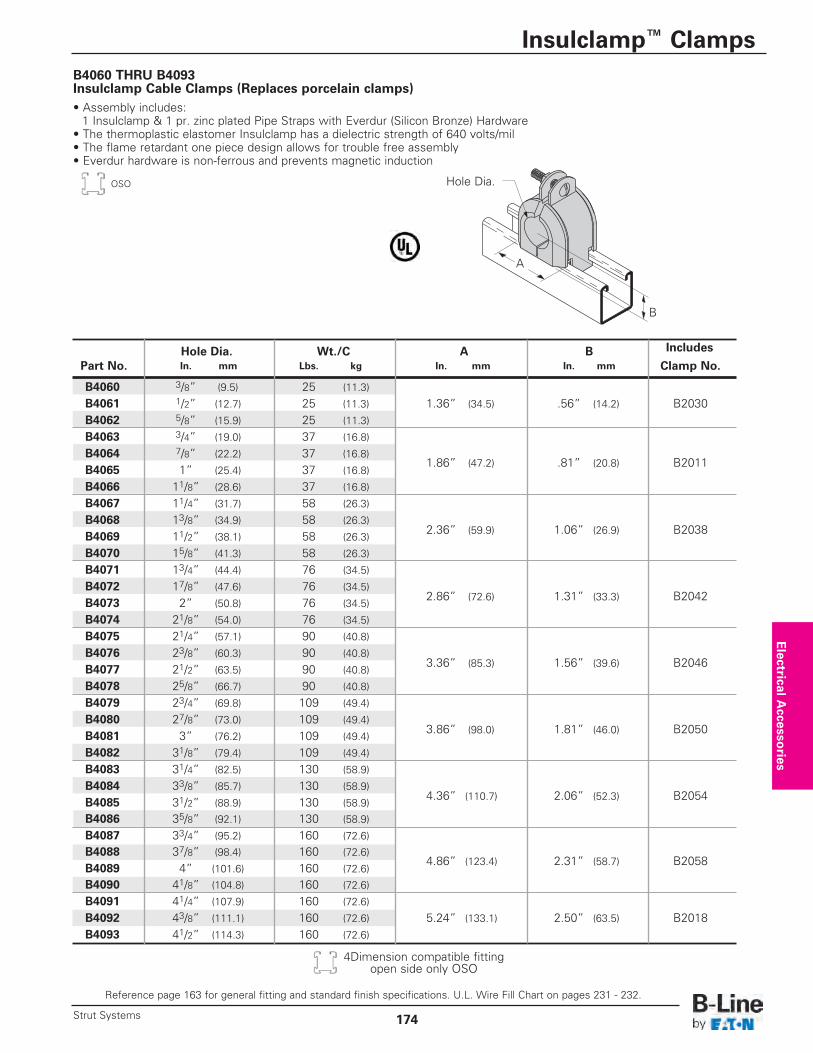
B4060 3/8” (9.5) 25 (11.3)
B4061 1/2” (12.7) 25 (11.3) 1.36” (34.5) .56” (14.2) B2030B4062 5/8” (15.9) 25 (11.3)
B4063 3/4” (19.0) 37 (16.8)
B4064 7/8” (22.2) 37 (16.8) 1.86” (47.2) .81” (20.8) B2011
B4065 1” (25.4) 37 (16.8)
B4066 11/8” (28.6) 37 (16.8)
B4067 11/4” (31.7) 58 (26.3)
B4068 13/8” (34.9) 58 (26.3)2.36” (59.9) 1.06” (26.9) B2038B4069 11/2” (38.1) 58 (26.3)
B4070 15/8” (41.3) 58 (26.3)
B4071 13/4” (44.4) 76 (34.5)
B4072 17/8” (47.6) 76 (34.5)2.86” (72.6) 1.31” (33.3) B2042B4073 2” (50.8) 76 (34.5)
B4074 21/8” (54.0) 76 (34.5)
B4075 21/4” (57.1) 90 (40.8)
B4076 23/8” (60.3) 90 (40.8)3.36” (85.3) 1.56” (39.6) B2046B4077 21/2” (63.5) 90 (40.8)
B4078 25/8” (66.7) 90 (40.8)
B4079 23/4” (69.8) 109 (49.4)
B4080 27/8” (73.0) 109 (49.4)3.86” (98.0) 1.81” (46.0) B2050B4081 3” (76.2) 109 (49.4)
B4082 31/8” (79.4) 109 (49.4)
B4083 31/4” (82.5) 130 (58.9)
B4084 33/8” (85.7) 130 (58.9)4.36” (110.7) 2.06” (52.3) B2054B4085 31/2” (88.9) 130 (58.9)
B4086 35/8” (92.1) 130 (58.9)
B4087 33/4” (95.2) 160 (72.6)
B4088 37/8” (98.4) 160 (72.6)4.86” (123.4) 2.31” (58.7) B2058
B4089 4” (101.6) 160 (72.6)
B4090 41/8” (104.8) 160 (72.6)
B4091 41/4” (107.9) 160 (72.6)
B4092 43/8” (111.1) 160 (72.6) 5.24” (133.1) 2.50” (63.5) B2018B4093 41/2” (114.3) 160 (72.6)
B4060 THRU B4093 Insulclamp Cable Clamps (Replaces porcelain clamps)• Assembly includes:1 Insulclamp & 1 pr. zinc plated Pipe Straps with Everdur (Silicon Bronze) Hardware
• The thermoplastic elastomer Insulclamp has a dielectric strength of 640 volts/mil • The flame retardant one piece design allows for trouble free assembly• Everdur hardware is non-ferrous and prevents magnetic induction
B
A
Hole Dia.
Electrical A
ccessories
Reference page 163 for general fitting and standard finish specifications. U.L. Wire Fill Chart on pages 231 - 232.
Insulclamp™ Clamps
174Strut Systems
OSO
4Dimension compatible fittingopen side only OSO
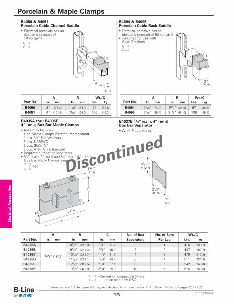
B4094 & B4095 Porcelain Cable Rack Saddle• Electrical porcelain has andielectric strength of 50 volts/mil
• Designed for use withB449 Brackets
B4050 & B4051 Porcelain Cable Channel Saddle• Electrical porcelain has andielectric strength of50 volts/mil
B4035A thru B4035F 4” (101.6) Bus Bar Maple Clamps• Assembly Includes:1 pr. Maple Clamps (Paraffin Impregnated)3 pcs. 1/2” Flat Washers3 pcs. N225WO3 pcs. SQN-1/2” 3 pcs. ATR-1/2 x L (Length)
• Required number of Separators• 1/4” (6.3) x 2” (50.8) and 1/4” (6.3) x 6” (152.4)Bus Bar Maple Clamps available
B4037B 1/4” (6.3) x 4” (101.6)Bus Bar Separator• Wt./C 9 Lbs. (4.1 kg)
A B C No. of Bus No. of Bars Wt./CPart No. In. mm In. mm In. mm Separators Per Leg Lbs. kg
B4035A 81/2” (215.9) 1/4” (6.3) – 1 416 (188.7)
B4035B 91/2” (241.3) 3/4” (19.0) 2 2 447 (202.7)
B4035C 73/8” (187.3)101/2” (266.7) 11/4” (31.7) 4 3 479 (217.3)
B4035D 111/2” (292.1) 13/4” (44.4) 6 4 511 (231.8)
B4035E 121/2” (317.5) 21/4” (57.1) 8 5 542 (245.8)
B4035F 131/2” (342.9) 23/4” (69.8) 10 6 574 (260.3)
x
A
R
21/4” (57.1)
x
A
R
3” (76.2)
A
B
C
15/8” (41.3)
47/16” (112.7)
31/2” (88.9)
1/4” (6.3)
Electrical Accessories
Reference page 163 for general fitting and standard finish specifications. U.L. Wire Fill Chart on pages 231 - 232.
Porcelain & Maple Clamps
Strut Systems175
A R Wt./CPart No. In. mm In. mm Lbs. kg
B4094 27/8” (73.0) 13/8” (34.9) 67 (30.4)
B4095 37/8” (98.4) 21/8” (54.0) 106 (48.1)
A R Wt./CPart No. In. mm In. mm Lbs. kg
B4050 3” (76.2) 13/8” (34.9) 72 (32.6)
B4051 4” (101.6) 21/8” (54.0) 100 (45.3)
OSO
4Dimension compatible fittingopen side only OSO
Discontinu
ed
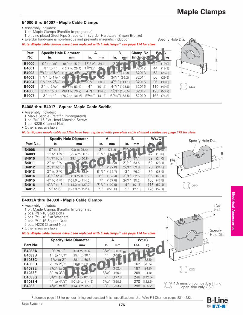
B4000 thru B4007 - Maple Cable Clamps • Assembly Includes:1 pr. Maple Clamps (Paraffin Impregnated)1 pr. zinc plated Steel Pipe Straps with Everdur Hardware (Silicon Bronze)
• Everdur hardware is non-ferrous and prevents magnetic inductionNote: Maple cable clamps have been replaced with Insulclamps™ see page 174 for sizes
B4008 thru B4017 - Square Maple Cable Saddle• Assembly Includes:1 Maple Saddle (Paraffin Impregnated)1 pc. 3/8”-16 Flat Head Machine Screw1 pc. N228 Channel Nut
• Other sizes availableNote: Square maple cable saddles have been replaced with porcelain cable channel saddles see page 175 for sizes
B4033A thru B4033I - Maple Cable Clamps• Assembly Includes:1 pr. Maple Clamps (Paraffin Impregnated)2 pcs. 3/8”-16 Stud Bolts2 pcs. 3/8”-16 Flat Washers2 pcs. 3/8”-16 Square Nuts2 pcs. N228 Channel Nuts
• Other sizes availableNote: Maple cable clamps have been replaced with Insulclamps™ see page 174 for sizes
Part Specify Hole Diameter A B Clamp No. Wt./CNo. In. mm In. mm In. mm (included) Lbs. kg
B4000 0” to 5/8” (0.0 to 15.9) 111/32” (34.1) 2” (50.8) B2010 24 (10.9)B4001 1/2” to 1” (12.7 to 25.4) 129/32” (48.4) 225/32”(70.6) B2012 44 (19.9)B4002 3/4” to 11/2” (19.0 to 38.1) 23/8” (60.3) 39/32” (83.3) B2013 58 (26.3)B4003 11/4” to 13/4” (31.7 to 44.4) 27/8” (73.0) 33/4” (95.2) B2014 66 (29.9)B4004 11/2” to 21/4” (38.1 to 57.1) 31/2” (88.9) 43/8” (111.1) B2015 86 (39.0)B4005 2” to 21/2” (50.8 to 63.5) 4” (101.6) 47/8” (123.8) B2016 110 (49.9)B4006 21/4” to 3” (38.1 to 76.2) 41/2” (114.3) 53/8” (136.5) B2017 125 (56.7)B4007 3” to 4” (76.2 to 101.6) 59/16” (141.3) 67/16”(163.5) B2019 165 (74.8)
B
A
Specify Hole Diameter A B Wt./CPart No. In. mm In. mm In. mm Lbs. kg
B4008 0” to 1” (0.0 to 25.4) 3” (76.2) 13/4” (44.4) 35 (15.9)B4009 1” to 11/2” (25.4 to 38.1) 31/2” (88.9) 2” (50.8) 42 (19.0)B4010 11/2” to 2” (38.1 to 50.8) 4” (101.6) 21/4” (57.1) 53 (24.0)B4011 2” to 21/2” (50.8 to 63.5) 41/2” (114.3) 21/2” (63.5) 62 (28.1)B4012 21/2” to 3” (63.5 to 76.2) 5” (127.0) 23/4” (69.8) 76 (34.5)B4013 3” to 31/2” (76.2 to 88.9) 51/2” (139.7) 3” (76.2) 85 (38.5)B4014 31/2” to 4” (88.9 to 101.6) 6” (152.4) 31/4” (82.5) 95 (43.1)B4015 4” to 41/2” (101.6 to 114.3) 7” (177.8) 33/4” (95.2) 105 (47.8)B4016 41/2” to 5” (114.3 to 127.0) 71/2” (190.5) 4” (101.6) 115 (52.4)B4017 5” to 6” (127.0 to 152.4) 9” (228.6) 5” (127.0) 126 (57.1)
A
B
15/8” (41.3)
15/8” (41.3)
Specify Hole Dia.
Specify Hole Dia.
Specify Hole Diameter A Wt./CPart No. In. mm In. mm Lbs. kg
B4033A 0” to 1” (0.0 to 25.4) 31/2” (88.9) 85 (38.5)B4033B 1” to 11/2” (25.4 to 38.1) 4” (101.6) 95 (43.1)B4033C 11/2 to 2” (38.1 to 50.8) 41/2” (114.3) 118 (53.5)B4033D 2” to 21/2” (50.8 to 63.5) 51/2” (127.0) 162 (73.5)B4033E 21/2” to 3” (63.5 to 76.2) 6” (152.4) 187 (84.8)B4033F 3” to 31/2” (76.2 to 88.9) 61/2” (165.1) 209 (94.8)B4033G 31/2” to 4” (88.9 to 101.6) 7” (177.8) 248 (112.5)B4033H 4” to 41/2” (101.6 to 114.3) 71/2” (190.5) 270 (122.5)B4033I 41/2” to 5” (114.3 to 127.0) 8” (203.2) 298 (135.2)
A
A
SpecifyHole Dia.
Electrical A
ccessories
Reference page 163 for general fitting and standard finish specifications. U.L. Wire Fill Chart on pages 231 - 232.
Maple Clamps
176Strut Systems
OSO
OSO
OSO
4Dimension compatible fittingopen side only OSO
Discontinu
ed
Discontinu
ed
Discontinu
ed
Recommended