NREL is a national laboratory of the U.S. Department of Energy, Office of Energy Efficiency and Renewable Energy, operated by the Alliance for Sustainable Energy, LLC.
Electric Motor Thermal Management R&D
P.I.: Kevin Bennion National Renewable Energy Laboratory 2016 Annual Merit Review Washington D. C. June 7, 2016
EDT064 NREL/PR-5400-66046
This presentation does not contain any proprietary, confidential, or otherwise restricted information.
2
Overview
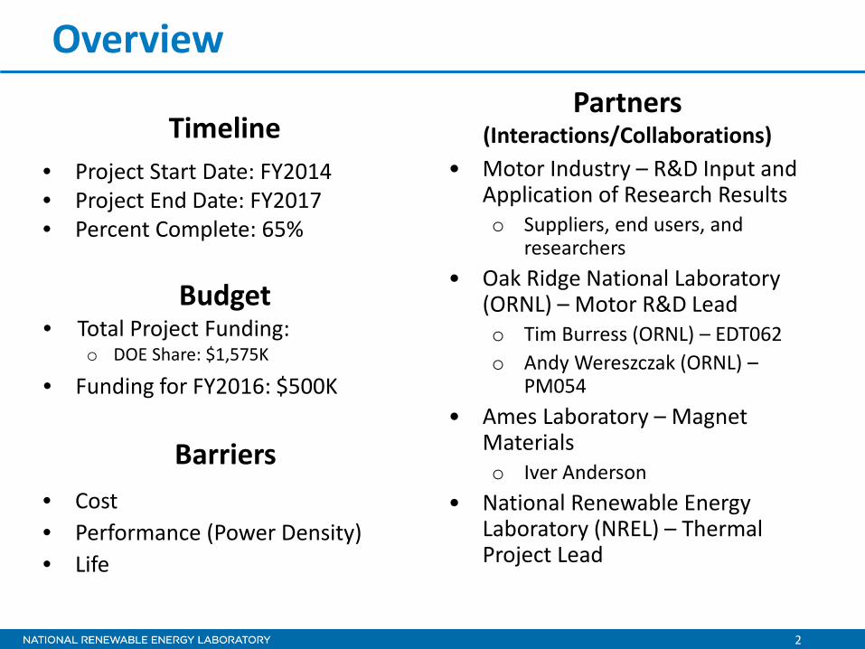
• Project Start Date: FY2014 • Project End Date: FY2017 • Percent Complete: 65%
• Cost • Performance (Power Density) • Life
• Total Project Funding: o DOE Share: $1,575K
• Funding for FY2016: $500K
Timeline
Budget
Barriers
• Motor Industry – R&D Input and Application of Research Results o Suppliers, end users, and
researchers • Oak Ridge National Laboratory
(ORNL) – Motor R&D Lead o Tim Burress (ORNL) – EDT062 o Andy Wereszczak (ORNL) –
PM054 • Ames Laboratory – Magnet
Materials o Iver Anderson
• National Renewable Energy Laboratory (NREL) – Thermal Project Lead
Partners (Interactions/Collaborations)
3
Relevance – Why Motor Cooling?
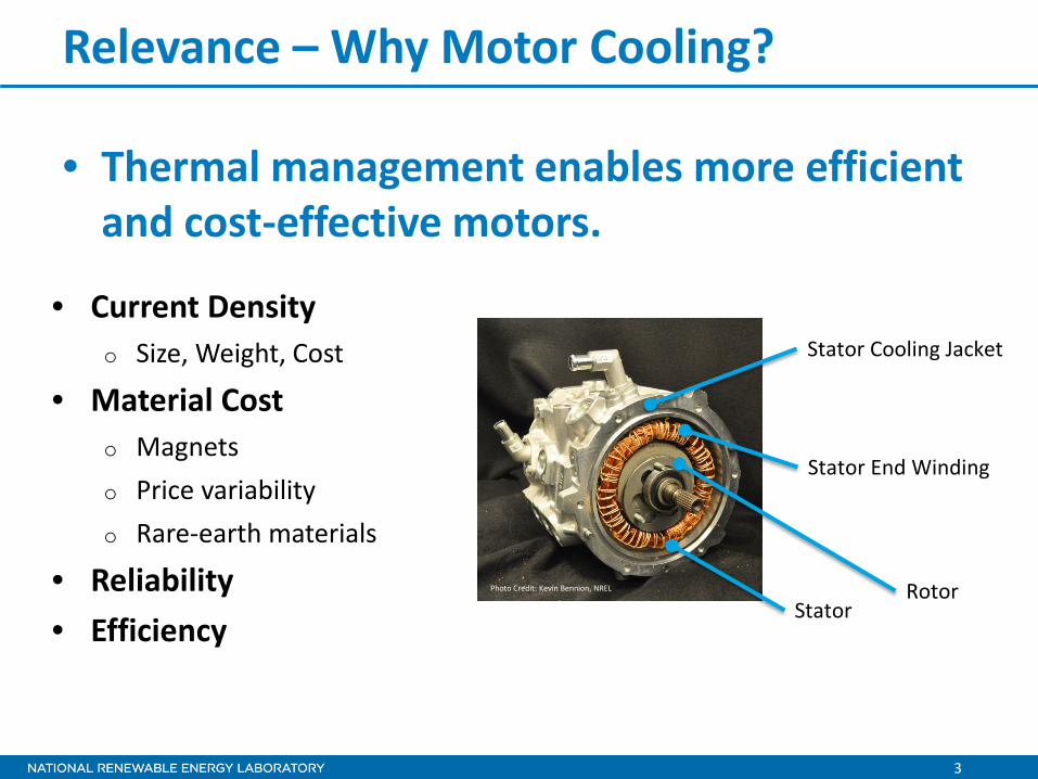
• Thermal management enables more efficient and cost-effective motors.
• Current Density o Size, Weight, Cost
• Material Cost o Magnets o Price variability o Rare-earth materials
• Reliability • Efficiency
Stator Cooling Jacket
Stator End Winding
Rotor Stator
Photo Credit: Kevin Bennion, NREL

4
Relevance – Research Objective
Problem
Core Thermal Capabilities and Research Tasks
Objective Support broad industry demand for data, analysis methods, and experimental techniques to improve and better understand motor thermal management
Stator Laminations
Slot-Winding
Rotor Laminations Rotor
Hub
Case
Air Gap
Stator-Case Contact
Nozzle/Orifice
ATF Impingement
Shaft ATF Flow
ATF Flow
Stator Cooling Jacket
End-Winding
Motor Axis
Motor Cooling Section View
ATF: Automatic Transmission Fluid

5
Milestones Date Description
December 2014 (Complete)
Milestone • Design test bench setup for measurement of ATF jet impingement on representative motor
end windings.
March 2015 (Complete)
Milestone • Perform thermal measurements on passive thermal materials in collaboration with ORNL.
June 2015 (Complete)
Go/No-Go • Select potting material for bench-level testing on representative motor components in
collaboration with ORNL.
September 2015 (Complete)
Milestone • Publish end-winding jet impingement heat transfer data and share with industry.
December 2015 (Complete)
Go/No-Go • Select alternative motor winding configurations and flow conditions for ATF experiments, and
select passive stack materials for characterization in collaboration with ORNL.
March 2016 (Complete)
Milestone • Complete preliminary measurements of ATF heat transfer coefficients on motor end
windings.
June 2016 (in progress)
Milestone • Complete design to incorporate motor rotor cooling and effects on cooling end windings.
September 2016 (in progress)
Milestone • Measure ATF heat transfer coefficients on motor end windings and passive stack thermal
resistance measurements. Prepare report to summarize project results.
6
Stator Laminations
Slot-Winding
Rotor Laminations Rotor
Hub
Case
Air Gap
Stator-Case Contact
Nozzle/Orifice
ATF Impingement
Shaft ATF Flow
ATF Flow
Stator Cooling Jacket
End-Winding
Motor Axis
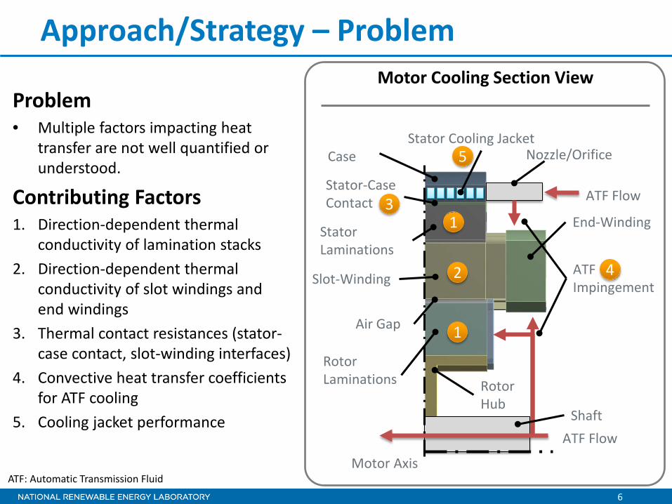
Approach/Strategy – Problem
Problem • Multiple factors impacting heat
transfer are not well quantified or understood.
Contributing Factors 1. Direction-dependent thermal
conductivity of lamination stacks 2. Direction-dependent thermal
conductivity of slot windings and end windings
3. Thermal contact resistances (stator-case contact, slot-winding interfaces)
4. Convective heat transfer coefficients for ATF cooling
5. Cooling jacket performance
4
1
1
2
3
5
Motor Cooling Section View
ATF: Automatic Transmission Fluid

7
Approach/Strategy – Focus
•Measure convective heat transfer coefficients for ATF cooling of end windings.
•Measure interface thermal resistances and orthotropic thermal conductivity of materials with ORNL.
•Support property measurements of magnet materials for Ames-led magnet efforts.
Support broad industry demand for data to improve and better understand motor thermal management.
Apply core thermal experimental and modeling capabilities.
Objective
Core Capabilities
Tasks
Automatic Transmission Fluid Heat Transfer
Material and Thermal Interface Testing
Photo Credit: Kevin Bennion, NREL
Photo Credit: Emily Cousineau, NREL
Material Sample Provided by ORNL

8
Technical Accomplishments
• Prior ATF heat transfer measurements performed with orifice jet
Target Surface (diameter 12.7 mm)
Sample Holder Heater Assembly
Nozzle
Fluid Inlet
Target
Reference: K. Bennion and G. Moreno, “Convective Heat Transfer Coefficients of Automatic Transmission Fluid Jets with Implications for Electric Machine Thermal Management,” in ASME 2015 International Technical Conference and Exhibition on Packaging and Integration of Electronic and Photonic Microsystems and ASME 2015 12th International Conference on Nanochannels, Microchannels, and Minichannels, San Francisco, CA, United States, 2015.
Front View Top View All of the fluid from the nozzle impinges onto the target surface and flows radially outward.
ℎ =𝑞𝑞𝑠𝑠
𝐴𝐴𝑠𝑠 𝑇𝑇𝑠𝑠 − 𝑇𝑇𝑙𝑙

9
Technical Accomplishments
• ATF heat transfer for flat fan jet
Target surface (diameter 12.7 mm)
Sample Holder Heater Assembly
Nozzle
Fluid Inlet
Target
BETE BJ04 Nozzle
Target distance 25.4 mm (1 inch)
Front View Side View Top View A portion of the fluid impinges on the target surface in a line across the target.
ℎ =𝑞𝑞𝑠𝑠
𝐴𝐴𝑠𝑠 𝑇𝑇𝑠𝑠 − 𝑇𝑇𝑙𝑙

10
Technical Accomplishments
• ATF heat transfer for flat fan jet
Flowrate of 0.6 l/min led to 58° spray angle
Photo Credit: Xuhui, Feng, NREL
Flowrate of 1.0 l/min led to 78° spray angle

11
Technical Accomplishments
• ATF heat transfer for flat fan jet
Inlet Coolant Temperature
0
1000
2000
3000
4000
5000
6000
7000
0 0.5 1 1.5 2
Hea
t Tra
nsfe
r Coe
ffici
ent (
W/m
2 K)
Flowrate (l/min)
50°C70°C90°C

12
Technical Accomplishments
• ATF pressure drop measurements for fan jet
0
2
4
6
8
10
12
14
0 0.5 1 1.5
Noz
zle
Pres
sure
Dro
p (p
si)
Flowrate (l/min)
50°C70°C90°C
Inlet Coolant Temperature

13
Technical Accomplishments
• For motor applications, the jet performance depends on more than the heat transfer coefficient over a small target surface
Photo Credit: Jana Jeffers and Xuhui Feng, NREL
Fan Jet
Orifice Jet • The following research is needed o Cooling tradeoffs with
pressure drop o Additional nozzle
configurations o Local versus large-scale heat
transfer coefficients

14
Technical Accomplishments
• Spatial mapping of large-scale end-winding convective heat transfer with direct ATF cooling
• Study effects of: o Oil jet placement o Nozzle type o ATF free flow over end-
winding surfaces o Jet interactions
• Assumptions: o Flat surface with texture of
wires
Photo Credit: Kevin Bennion, NREL

15
Technical Accomplishments
• Designed and built sensor packages to install in motor end winding for measuring heat transfer coefficients 3D drawing of stator with
sensor packages installed
Photo Credits: Kevin Bennion, NREL
Stator winding removed for sensor package

16
Technical Accomplishments
• Sensor package construction
Flat 18 AWG 20 AWG
Sensor Package
Targets
Exploded View
Heater

17
Technical Accomplishments
Target surfaces built to represent wire surface with different wire sizes
Assembled test fixture for outer diameter heat transfer
measurement
Assembled test fixture for end-surface heat transfer
measurement Photo Credit: Emily Cousineau, NREL

18
Technical Accomplishments
• Enclosure allows direct impingement on motor for heat transfer measurements and flow visualization
Enclosure with stator and ATF cooling Jet impingement on target surface
Photo Credit: Kevin Bennion, NREL

19
Technical Accomplishments
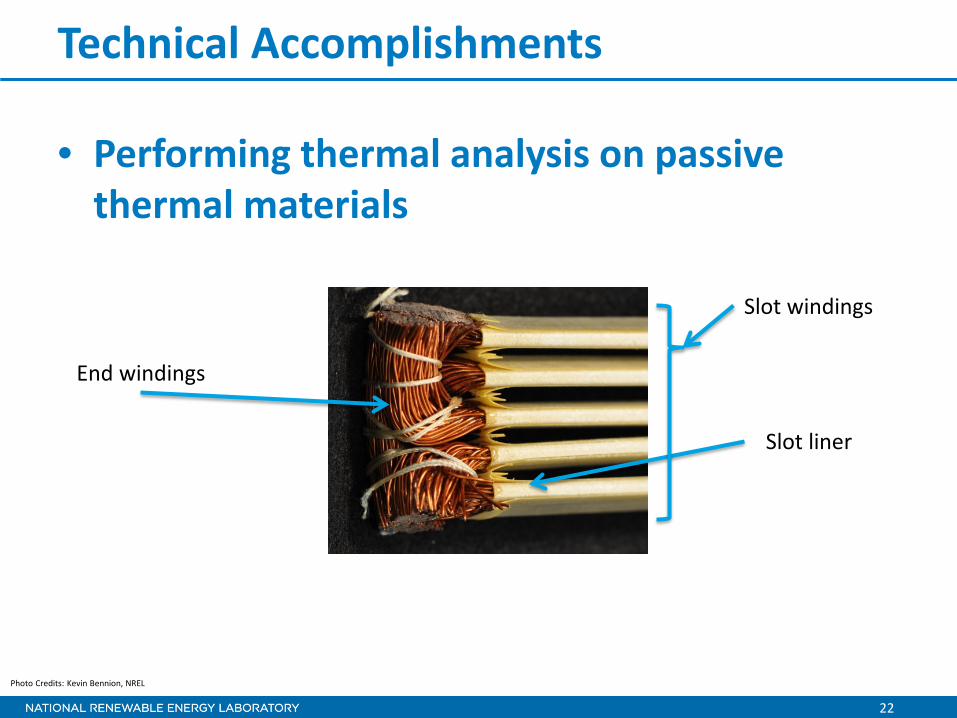
• Performing thermal analysis on passive thermal materials
Slot windings
Slot liner or ground insulation
Stator laminations
Measure cross-slot winding thermal conductivity
Measure winding-to-liner thermal contact resistance
Measure liner-to-stator thermal contact resistance

20
Technical Accomplishments
• Performing thermal analysis on passive thermal materials o ORNL prepared slot-winding samples with variations for:
– Wire size (19 AWG, 22 AWG) – Sample thickness
o Collaborating with ORNL on thermal conductivity measurement techniques
Photo Credits: Justin Cousineau, NREL
Winding sample blocks prepared by ORNL Photo Credit: Emily Cousineau, NREL
19 AWG Axial
19 AWG Transverse

21
Technical Accomplishments
• Transverse winding results
0.00.20.40.60.81.01.21.41.61.8
3 4 5 6 7
Ther
mal
Con
duct
ivity
[W/m
-K]
Sample Thickness [mm]
22 AWG Transverse
data
FEA
0.00.20.40.60.81.01.21.41.61.8
3 4 5 6 7Th
erm
al C
ondu
ctiv
ity [W
/m-K
] Sample Thickness [mm]
19 AWG Transverse
data
FEA
• Error bars represent 95% measurement uncertainty (U95) • Finite element analysis (FEA) model result based on measured sample copper fill factor • FEA assumes hexagonal or closed-pack wire pattern
22
Technical Accomplishments
• Performing thermal analysis on passive thermal materials
Photo Credits: Kevin Bennion, NREL
End windings
Slot windings
Slot liner

23
Technical Accomplishments
• Measured passive thermal materials and interfaces
• Limited sample size for measurements
• Slot liner paper thermal conductivity of 0.175 W/m-K (thickness 0.294 mm)
• Winding thermal conductivity measured to be 0.88 ± 0.11 W/m-K (U95)
• FEA estimate of thermal conductivity is 0.99 W/m-K for measured copper fill factor
Slot Liner Paper and Thermal Interfaces
0
1000
2000
3000
Slot Liner Paper Paper to Windingbond
Paper to Flat Copper
Laye
r The
rmal
Res
ista
nce
[mm
²-K/
W]

24
Response to Previous Year Reviewers’ Comments
• Reviewers thought the passive material measurements and heat transfer coefficients were important and the data is valuable. It was suggested that it would be great to publish and present results. o This past year, we have published and presented results related to prior work,
and we are working with ORNL on publishing our data on winding thermal measurements. We will work to focus on publishing results.
• Reviewer said it would be good to include more details that make the testing more realistic to what takes place in a real motor. Another reviewer mentioned or highlighted an interest in bar wound stators. o We have constructed a new test setup allowing thermal testing on more
representative motor and stator geometries. This should also enable potential collaborative work related to bar-wound stators and other geometries.
• The reviewer’s analysis was that there is potential for increased collaboration, exchange of data/comparison with GE, the other group that is testing end winding impingement cooling. The reviewer suggested considering collaborating with universities as well. o We have tried to increase our collaborations as suggested.
25
Collaboration and Coordination with Other Institutions
• Industry o Motor industry suppliers, end users, and researchers
– Sharing experimental data, modeling results, and analysis methods – Companies providing research comments, requesting data, or supplying
data or motor material information include: Ford, FCA, GM, Tesla, UQM Technologies, GE Global Research, Remy/BorgWarner, John Deere, Oshkosh, motor material manufacturers
• Other Government Laboratories o ORNL
– Support from benchmarking activities – Collaboration on motor designs to reduce or eliminate rare-earth
materials – Collaboration on materials with improved thermal properties
o Ames – NREL supporting magnet material physical property measurements

26
Remaining Challenges and Barriers
Cooling Technology Development
• Thermal tests of interfaces between slot insulation and laminations, and slot insulation and slot windings
• Irregular structure of certain end windings present a challenge to measure thermal conductivity
• Heat transfer coefficients of ATF impingement on irregular surfaces of motor end windings
• Impact of alternative winding configurations that would change the end-winding form factor or geometry leading to different fluid flow and heat transfer (bar windings, concentrated windings)
Passive Thermal Stack and Reliability
Photo Credit: Gilbert Moreno, NREL Photo Credit: Gilbert Moreno, NREL
Photo Credit: Sreekant Narumanchi, NREL Photo Credit: Doug Devoto, NREL

27
Proposed Future Work
FY2016 • Continue ongoing collaboration with ORNL material developments and motor
research. • Measure passive stack thermal interfaces and orthotropic thermal properties
of materials in collaboration with ORNL. Publish results with ORNL. • Measure physical properties as a function of temperature for Ames
Laboratory on new magnet materials developed at Ames. • Measure large-scale variation in ATF impingement heat transfer coefficients
within a stator - supporting fourth-quarter milestone. • Share and publish fan jet heat transfer results. FY2017 • Characterize alternative ATF cooling sprays and end-winding geometry in
motor-scale thermal measurements. • Continue collaborative efforts with ORNL and Ames on material
measurements representative of motor materials. • Initiate efforts on rotor thermal management in collaboration with research
partners.
Photo Credit: Kevin Bennion, NREL

28
Summary Relevance • Supports transition to more electric-drive vehicles with higher continuous power requirements. • Enables improved performance of motors without and with non-rare earth materials.
Approach/Strategy • Engage in collaborations with motor design experts within industry. • Collaborate with ORNL to provide motor thermal analysis support on related motor research at ORNL. • Collaborate with Ames to provide material properties to support Ames-led magnet development. • Perform in-house thermal characterization of materials, interface thermal properties, and cooling
techniques.
Technical Accomplishments • Completed measurement of fan jet nozzle for ATF heat transfer in motor application in collaboration
with industry partner. • Built experimental apparatus to measure large-scale variation in convective heat transfer coefficients. • Collaborating with ORNL on measurement techniques to quantify thermal properties of passive stack
materials within motor stators. • Collaborating with Ames on mechanical and thermal measurements on magnet materials. Collaborations • Motor industry representatives: manufacturers, researchers, and end users (light-duty and
medium/heavy-duty applications). • Oak Ridge National Laboratory. • Ames Laboratory.

For more information, contact:
Principal Investigator Kevin Bennion [email protected] Phone: (303)-275-4447
EDT Task Leader:
Sreekant Narumanchi [email protected] Phone: (303)-275-4062
Acknowledgments:
Susan Rogers and Steven Boyd, U.S. Department of Energy Team Members:
Emily Cousineau (NREL) Doug DeVoto (NREL) Xuhui Feng (NREL) Charlie King (NREL) Gilbert Moreno (NREL) Tim Burress (ORNL) Andy Wereszczak (ORNL) Iver Anderson (Ames)
Recommended