7-13
E
– +
ELEC IGNITION SYSTEM
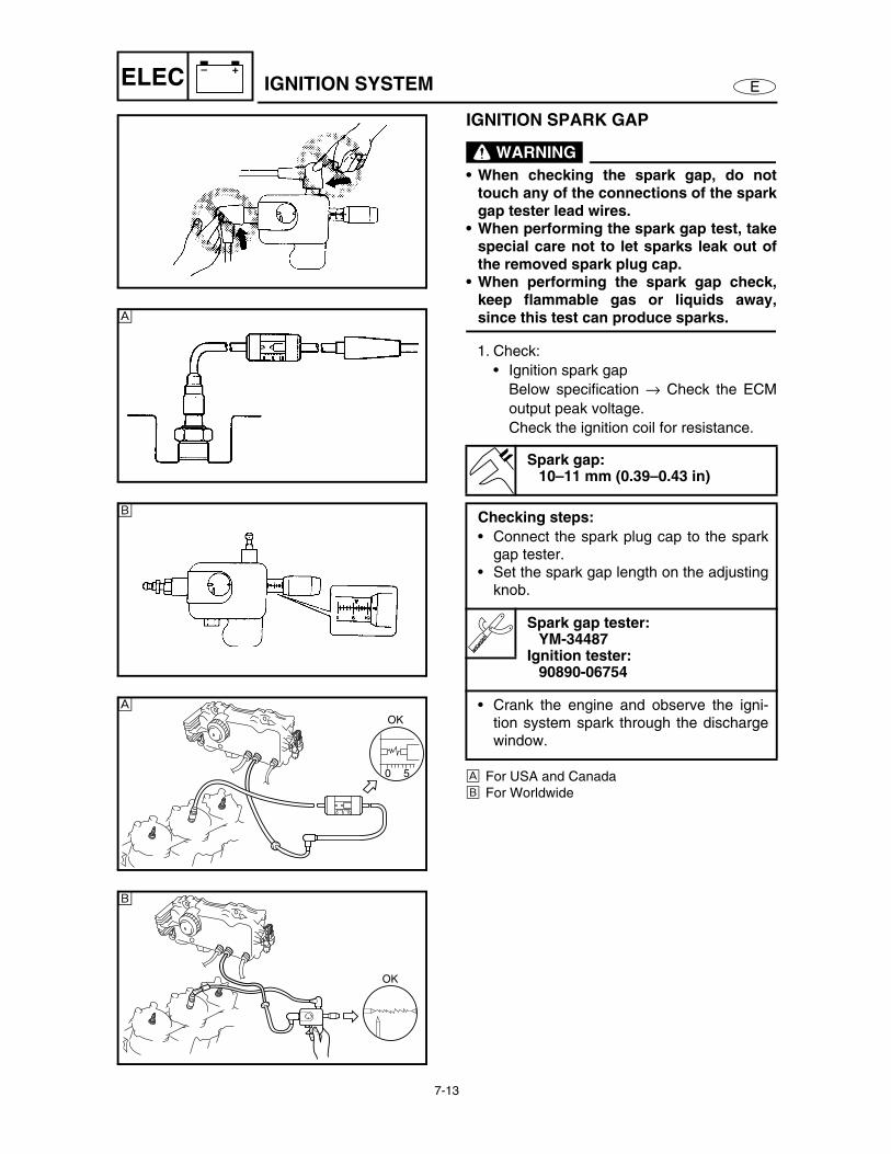
IGNITION SPARK GAP
WARNING
• When checking the spark gap, do nottouch any of the connections of the sparkgap tester lead wires.
• When performing the spark gap test, takespecial care not to let sparks leak out ofthe removed spark plug cap.
• When performing the spark gap check,keep flammable gas or liquids away,since this test can produce sparks.
1. Check:
• Ignition spark gap
Below specification → Check the ECM
output peak voltage.
Check the ignition coil for resistance.
È For USA and Canada
É For Worldwide
Spark gap:10–11 mm (0.39–0.43 in)
Checking steps:
• Connect the spark plug cap to the sparkgap tester.
• Set the spark gap length on the adjustingknob.
Spark gap tester:YM-34487
Ignition tester:90890-06754
• Crank the engine and observe the igni-tion system spark through the dischargewindow.
È
É
0 5
OK
0 5 10
È
OK
É
7-14
E
– +
ELEC IGNITION SYSTEM
IGNITION SYSTEM PEAK VOLTAGE
WARNING
When checking the electrical components,
do not touch any of the connections of the
digital tester lead wires.
NOTE:• If there is no spark, or the spark is weak,
continue with the ignition system test.
• If a good spark is obtained, the problem is
not with the ignition system, but possibly with
the spark plug(s) or another component.
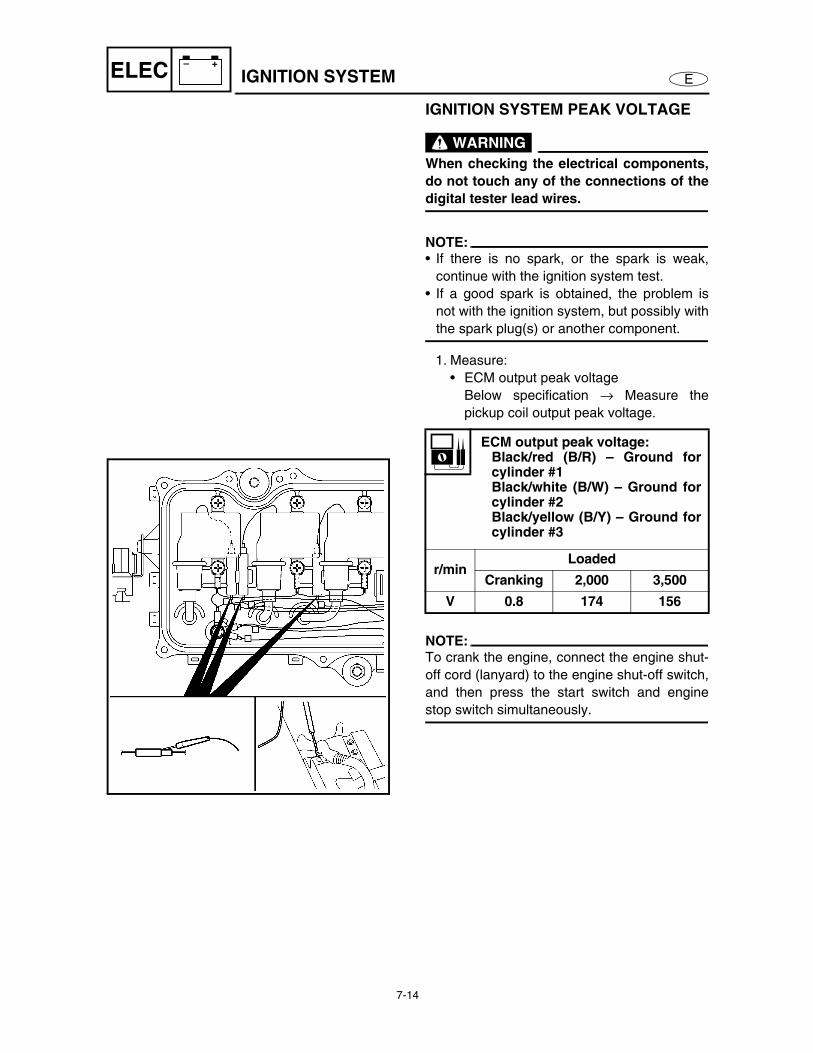
1. Measure:
• ECM output peak voltage
Below specification → Measure the
pickup coil output peak voltage.
NOTE:To crank the engine, connect the engine shut-
off cord (lanyard) to the engine shut-off switch,
and then press the start switch and engine
stop switch simultaneously.
ECM output peak voltage:Black/red (B/R) – Ground forcylinder #1Black/white (B/W) – Ground forcylinder #2Black/yellow (B/Y) – Ground forcylinder #3
r/minLoaded
Cranking 2,000 3,500
V 0.8 174 156
7-15
E
– +
ELEC IGNITION SYSTEM
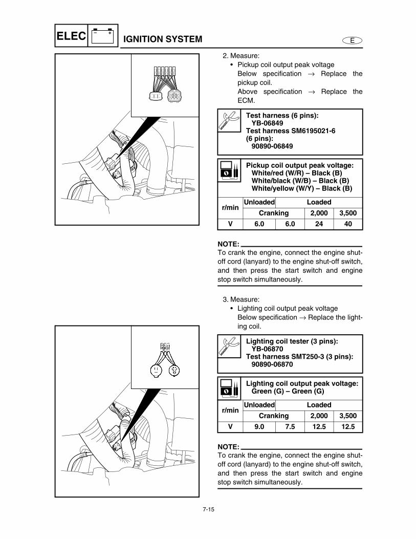
2. Measure:
• Pickup coil output peak voltage
Below specification → Replace the
pickup coil.
Above specification → Replace the
ECM.
NOTE:To crank the engine, connect the engine shut-
off cord (lanyard) to the engine shut-off switch,
and then press the start switch and engine
stop switch simultaneously.
3. Measure:
• Lighting coil output peak voltage
Below specification → Replace the light-
ing coil.
NOTE:To crank the engine, connect the engine shut-
off cord (lanyard) to the engine shut-off switch,
and then press the start switch and engine
stop switch simultaneously.
Test harness (6 pins):YB-06849
Test harness SM6195021-6 (6 pins):
90890-06849
Pickup coil output peak voltage:White/red (W/R) – Black (B)White/black (W/B) – Black (B)White/yellow (W/Y) – Black (B)
r/minUnloaded Loaded
Cranking 2,000 3,500
V 6.0 6.0 24 40
Lighting coil tester (3 pins):YB-06870
Test harness SMT250-3 (3 pins):90890-06870
Lighting coil output peak voltage:Green (G) – Green (G)
r/minUnloaded Loaded
Cranking 2,000 3,500
V 9.0 7.5 12.5 12.5
7-16
E
– +
ELEC
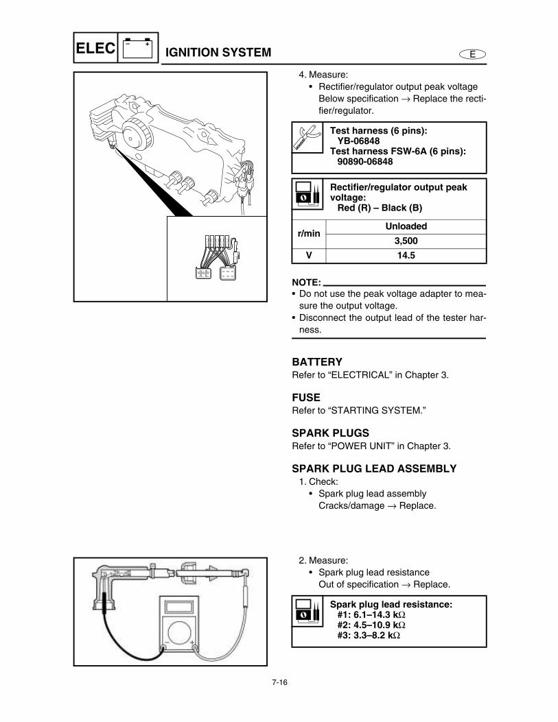
4. Measure:
• Rectifier/regulator output peak voltage
Below specification → Replace the recti-
fier/regulator.
NOTE:• Do not use the peak voltage adapter to mea-
sure the output voltage.
• Disconnect the output lead of the tester har-
ness.
BATTERYRefer to “ELECTRICAL” in Chapter 3.
FUSERefer to “STARTING SYSTEM.”
SPARK PLUGSRefer to “POWER UNIT” in Chapter 3.
SPARK PLUG LEAD ASSEMBLY1. Check:
• Spark plug lead assembly
Cracks/damage → Replace.
Test harness (6 pins):YB-06848
Test harness FSW-6A (6 pins):90890-06848
Rectifier/regulator output peak voltage:
Red (R) – Black (B)
r/minUnloaded
3,500
V 14.5
2. Measure:
• Spark plug lead resistance
Out of specification → Replace.
Spark plug lead resistance:#1: 6.1–14.3 kΩ
#2: 4.5–10.9 kΩ
#3: 3.3–8.2 kΩ
IGNITION SYSTEM
7-17
E
– +
ELEC
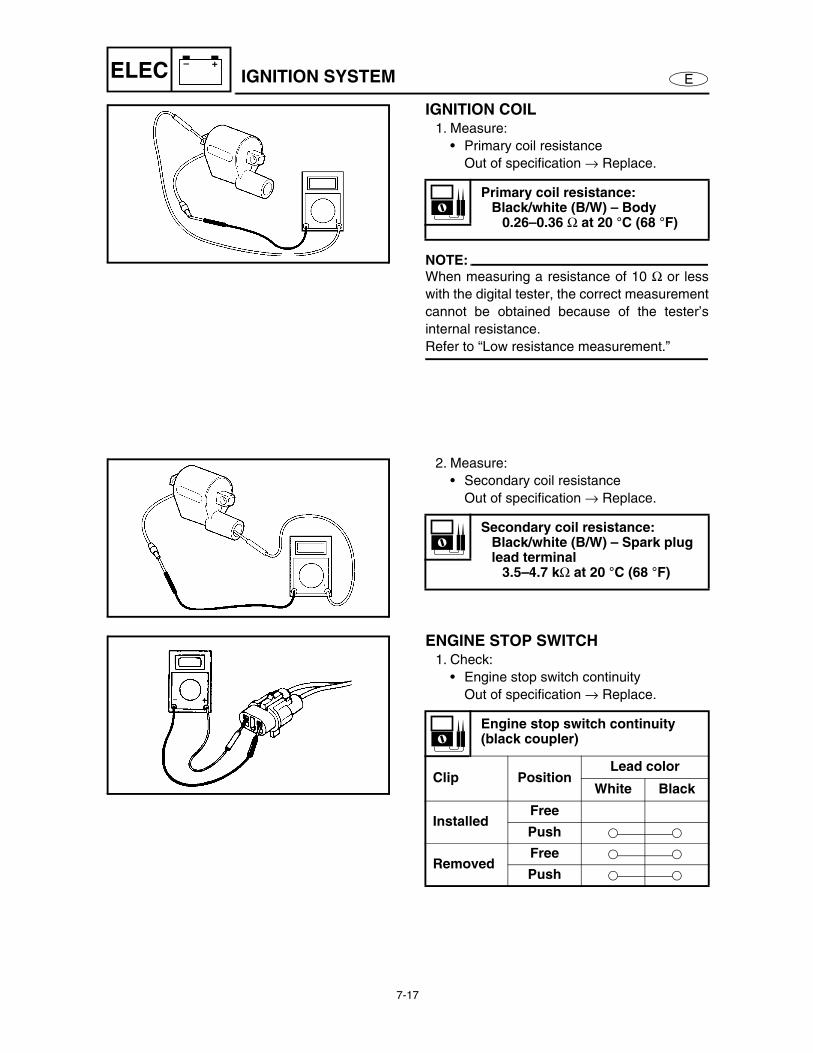
IGNITION COIL1. Measure:
• Primary coil resistance
Out of specification → Replace.
NOTE:When measuring a resistance of 10 Ω or less
with the digital tester, the correct measurement
cannot be obtained because of the tester’s
internal resistance.
Refer to “Low resistance measurement.”
Primary coil resistance:Black/white (B/W) – Body
0.26–0.36 Ω at 20 °C (68 °F)
2. Measure:
• Secondary coil resistance
Out of specification → Replace.
Secondary coil resistance:Black/white (B/W) – Spark plug lead terminal
3.5–4.7 kΩ at 20 °C (68 °F)
ENGINE STOP SWITCH1. Check:
• Engine stop switch continuity
Out of specification → Replace.
Engine stop switch continuity(black coupler)
Clip PositionLead color
White Black
InstalledFree
Push
RemovedFree
Push
IGNITION SYSTEM
7-18
E
– +
ELEC IGNITION SYSTEM
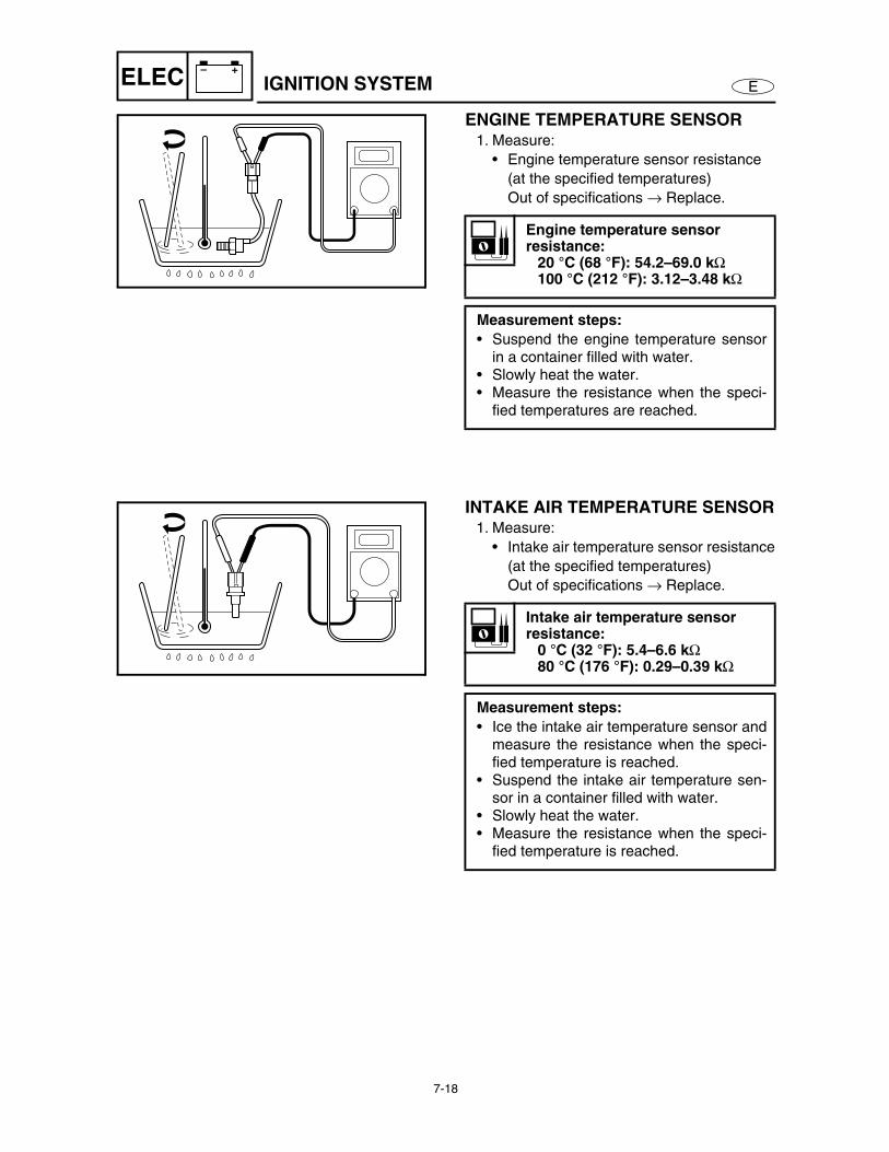
ENGINE TEMPERATURE SENSOR1. Measure:
• Engine temperature sensor resistance
(at the specified temperatures)
Out of specifications → Replace.
Engine temperature sensor resistance:
20 °C (68 °F): 54.2–69.0 kΩ 100 °C (212 °F): 3.12–3.48 kΩ
Measurement steps:
• Suspend the engine temperature sensorin a container filled with water.
• Slowly heat the water.• Measure the resistance when the speci-
fied temperatures are reached.
INTAKE AIR TEMPERATURE SENSOR1. Measure:
• Intake air temperature sensor resistance
(at the specified temperatures)
Out of specifications → Replace.
Intake air temperature sensor resistance:
0 °C (32 °F): 5.4–6.6 kΩ 80 °C (176 °F): 0.29–0.39 kΩ
Measurement steps:
• Ice the intake air temperature sensor andmeasure the resistance when the speci-fied temperature is reached.
• Suspend the intake air temperature sen-sor in a container filled with water.
• Slowly heat the water.• Measure the resistance when the speci-
fied temperature is reached.
7-19
E
– +
ELEC IGNITION SYSTEM
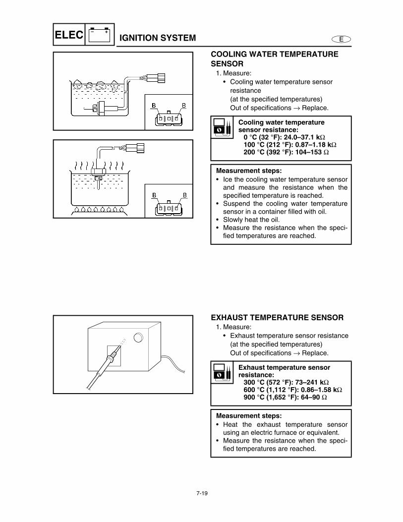
COOLING WATER TEMPERATURE
SENSOR1. Measure:
• Cooling water temperature sensor
resistance
(at the specified temperatures)
Out of specifications → Replace.
Cooling water temperature sensor resistance:
0 °C (32 °F): 24.0–37.1 kΩ 100 °C (212 °F): 0.87–1.18 kΩ 200 °C (392 °F): 104–153 Ω
Measurement steps:
• Ice the cooling water temperature sensorand measure the resistance when thespecified temperature is reached.
• Suspend the cooling water temperaturesensor in a container filled with oil.
• Slowly heat the oil.• Measure the resistance when the speci-
fied temperatures are reached.
EXHAUST TEMPERATURE SENSOR1. Measure:
• Exhaust temperature sensor resistance
(at the specified temperatures)
Out of specifications → Replace.
Exhaust temperature sensor resistance:
300 °C (572 °F): 73–241 kΩ 600 °C (1,112 °F): 0.86–1.58 kΩ 900 °C (1,652 °F): 64–90 Ω
Measurement steps:
• Heat the exhaust temperature sensorusing an electric furnace or equivalent.
• Measure the resistance when the speci-fied temperatures are reached.
7-20
E
– +
ELEC IGNITION SYSTEM
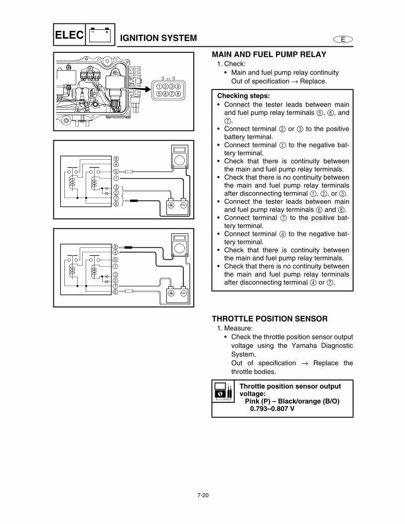
MAIN AND FUEL PUMP RELAY1. Check:
• Main and fuel pump relay continuity
Out of specification → Replace.
Checking steps:
• Connect the tester leads between mainand fuel pump relay terminals 5, 6, and7.
• Connect terminal 2 or 3 to the positivebattery terminal.
• Connect terminal 1 to the negative bat-tery terminal.
• Check that there is continuity betweenthe main and fuel pump relay terminals.
• Check that there is no continuity betweenthe main and fuel pump relay terminalsafter disconnecting terminal 1, 2, or 3.
• Connect the tester leads between mainand fuel pump relay terminals 6 and 8.
• Connect terminal 7 to the positive bat-tery terminal.
• Connect terminal 4 to the negative bat-tery terminal.
• Check that there is continuity betweenthe main and fuel pump relay terminals.
• Check that there is no continuity betweenthe main and fuel pump relay terminalsafter disconnecting terminal 4 or 7.
1234
5678
+ –
84
5
1
3276
+ –
84
5
1
3276
THROTTLE POSITION SENSOR1. Measure:
• Check the throttle position sensor output
voltage using the Yamaha Diagnostic
System.
Out of specification → Replace the
throttle bodies.
Throttle position sensor output voltage:
Pink (P) – Black/orange (B/O)0.793–0.807 V
7-21
E
– +
ELEC IGNITION SYSTEM
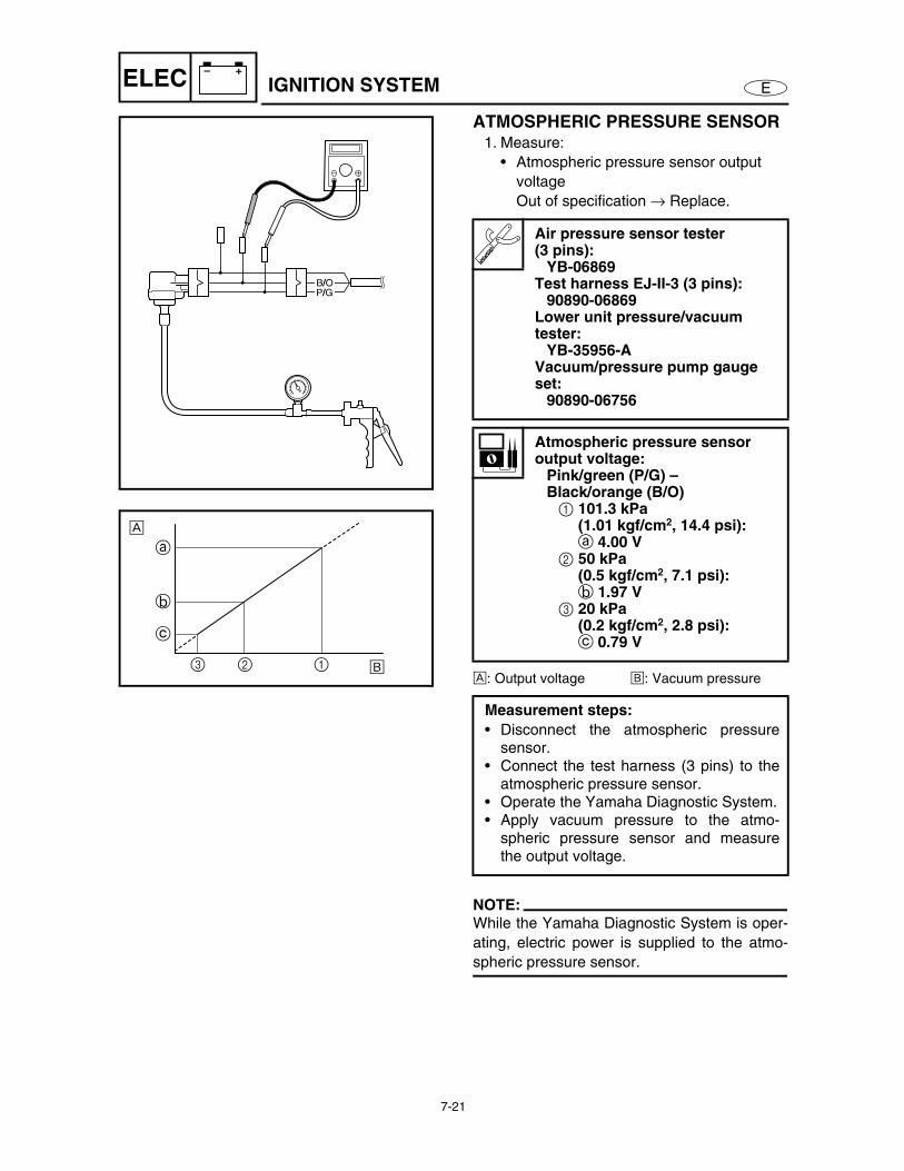
ATMOSPHERIC PRESSURE SENSOR1. Measure:
• Atmospheric pressure sensor output
voltage
Out of specification → Replace.
È: Output voltage É: Vacuum pressure
NOTE:While the Yamaha Diagnostic System is oper-
ating, electric power is supplied to the atmo-
spheric pressure sensor.
Air pressure sensor tester (3 pins):
YB-06869Test harness EJ-II-3 (3 pins):
90890-06869Lower unit pressure/vacuum tester:
YB-35956-AVacuum/pressure pump gauge set:
90890-06756
Atmospheric pressure sensor output voltage:
Pink/green (P/G) – Black/orange (B/O)1 101.3 kPa
(1.01 kgf/cm2, 14.4 psi):a 4.00 V
2 50 kPa (0.5 kgf/cm2, 7.1 psi):b 1.97 V
3 20 kPa (0.2 kgf/cm2, 2.8 psi):c 0.79 V
Measurement steps:
• Disconnect the atmospheric pressuresensor.
• Connect the test harness (3 pins) to theatmospheric pressure sensor.
• Operate the Yamaha Diagnostic System.• Apply vacuum pressure to the atmo-
spheric pressure sensor and measurethe output voltage.
B/OP/G
È
a
b
c
3 2 1 É
7-22
E
– +
ELEC IGNITION SYSTEM
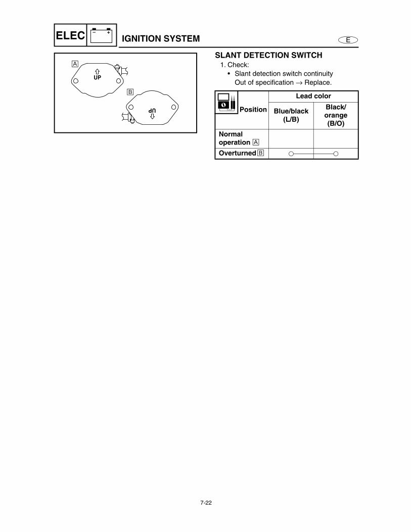
SLANT DETECTION SWITCH1. Check:
• Slant detection switch continuity
Out of specification → Replace.
Position
Lead color
Blue/black (L/B)
Black/orange (B/O)
Normal operation È
Overturned É
UP
UP
È
É
7-23
E
– +
ELEC FUEL CONTROL SYSTEM
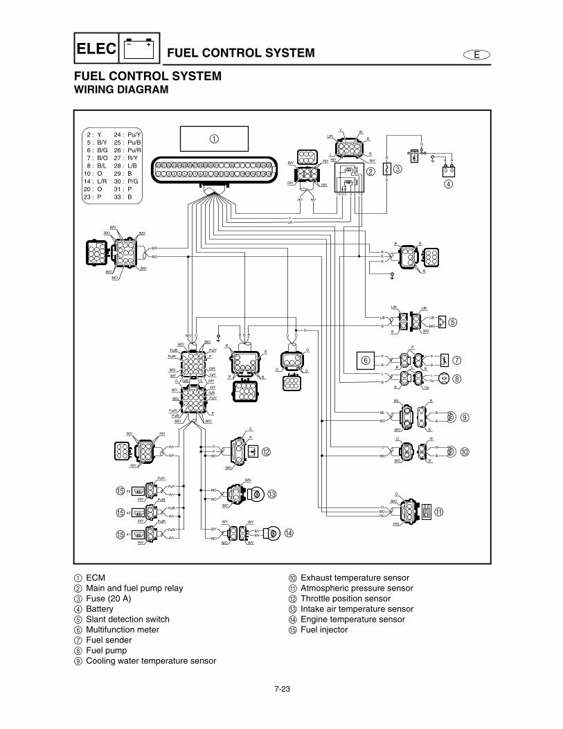
FUEL CONTROL SYSTEMWIRING DIAGRAM
33313029282720
2 5 6 7 8 10 14
262524232221 32
1 4 9 15 16 17 18 193 11 12 13
3534
Pu/Y
Pu/B
Pu/R
R/Y
L/B
B
P/G
P
B
24 :
25 :
26 :
27 :
28 :
29 :
30 :
31 :
33 :
Y
B/Y
B/G
B/O
B/L
O
L/R
O
P
2 :
5 :
6 :
7 :
8 :
10 :
14 :
20 :
23 :
B/O
B/O
B/O
P
B/O
B/O
B/L
B/O
B
B/O
P/G
B
B
WO
O
B
123 4 567 8
R
R
R
R
B
B
B
R/YR/Y
Pu/R
R/Y
Pu/B
R/Y
Pu/Y
B/O
B/O
R/Y
BB B
#1
#2
#3
B/O
L/B
P
B
L
Gy
P
B
L
B
B
L/B
O
P
B/G
B/O
B/O
B/Y
B/Y
B/Y
B/O
B/O
B/Y
B/Y
B/Y
Pu/R
Pu/B
B/O B/O
P
Pu/Y
G/R
R/YOG
B/G
G/B
G/YB/Y
Pu/R
B/Y
B/G
G/Y
B/OB/O
Pu/B Pu/Y
P
G/R
O
R/Y R/Y
B/G
B/O
B/O
L/B
B
L/B
OO
O
B
B B
R/Y
R/Y
R/Y
R/YR/Y
R
Br
BL/R
Y
L
R/Y
B/L
B/O
B
B
B/O
O
O
P/G
B/O
W
B
B
B
BB
L BB
B Gy
O
OOO
B/O
P
R/Y
R/Y
R/Y
R/Y
R/Y Pu/R
Pu/B
Pu/Y
R/Y
B/O
B/O
L/R
Y
B/O
1
2 3
4
6 7
8
9
0
A
B
C
DE
E
E
5
1 ECM
2 Main and fuel pump relay
3 Fuse (20 A)
4 Battery
5 Slant detection switch
6 Multifunction meter
7 Fuel sender
8 Fuel pump
9 Cooling water temperature sensor
0 Exhaust temperature sensor
A Atmospheric pressure sensor
B Throttle position sensor
C Intake air temperature sensor
D Engine temperature sensor
E Fuel injector
7-24
E
– +
ELEC FUEL CONTROL SYSTEM
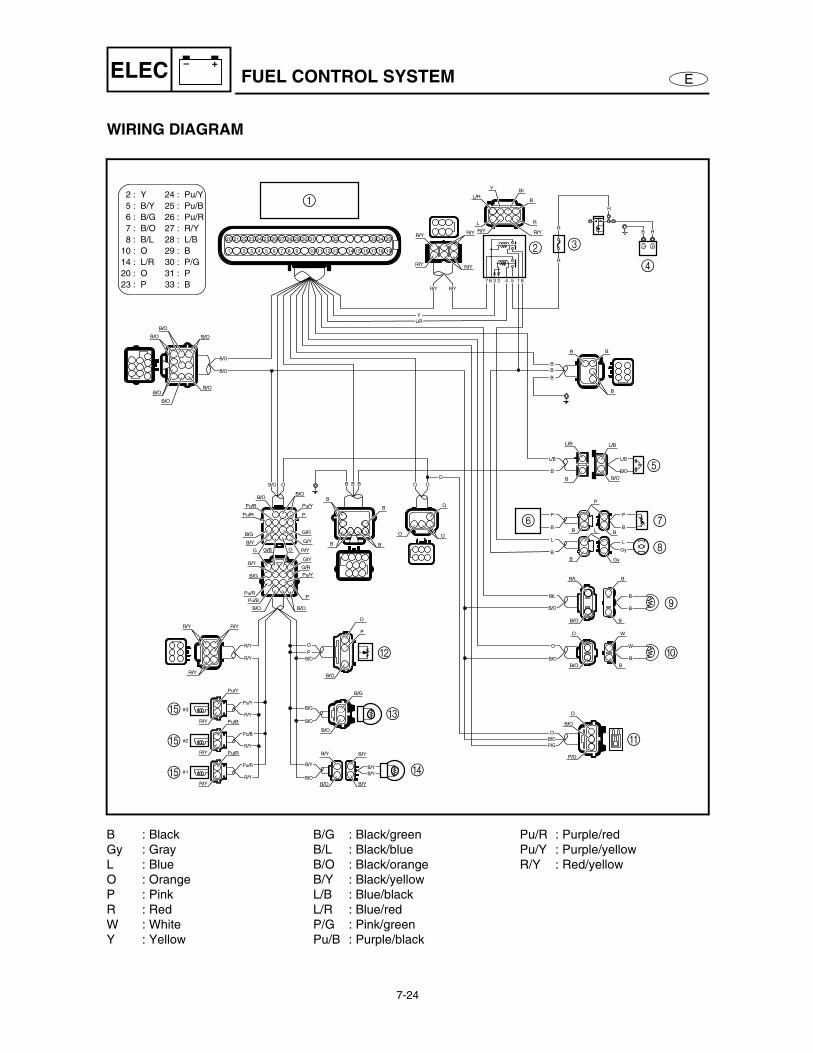
WIRING DIAGRAM
33313029282720
2 5 6 7 8 10 14
262524232221 32
1 4 9 15 16 17 18 193 11 12 13
3534
Pu/Y
Pu/B
Pu/R
R/Y
L/B
B
P/G
P
B
24 :
25 :
26 :
27 :
28 :
29 :
30 :
31 :
33 :
Y
B/Y
B/G
B/O
B/L
O
L/R
O
P
2 :
5 :
6 :
7 :
8 :
10 :
14 :
20 :
23 :
B/O
B/O
B/O
P
B/O
B/O
B/L
B/O
B
B/O
P/G
B
B
WO
O
B
123 4 567 8
R
R
R
R
B
B
B
R/YR/Y
Pu/R
R/Y
Pu/B
R/Y
Pu/Y
B/O
B/O
R/Y
BB B
#1
#2
#3
B/O
L/B
P
B
L
Gy
P
B
L
B
B
L/B
O
P
B/G
B/O
B/O
B/Y
B/Y
B/Y
B/O
B/O
B/Y
B/Y
B/Y
Pu/R
Pu/B
B/O B/O
P
Pu/Y
G/R
R/YOG
B/G
G/B
G/YB/Y
Pu/R
B/Y
B/G
G/Y
B/OB/O
Pu/B Pu/Y
P
G/R
O
R/Y R/Y
B/G
B/O
B/O
L/B
B
L/B
OO
O
B
B B
R/Y
R/Y
R/Y
R/YR/Y
R
Br
BL/R
Y
L
R/Y
B/L
B/O
B
B
B/O
O
O
P/G
B/O
W
B
B
B
BB
L BB
B Gy
O
OOO
B/O
P
R/Y
R/Y
R/Y
R/Y
R/Y Pu/R
Pu/B
Pu/Y
R/Y
B/O
B/O
L/R
Y
B/O
1
2 3
4
6 7
8
9
0
A
B
C
DE
E
E
5
B : Black
Gy : Gray
L : Blue
O : Orange
P : Pink
R : Red
W : White
Y : Yellow
B/G : Black/green
B/L : Black/blue
B/O : Black/orange
B/Y : Black/yellow
L/B : Blue/black
L/R : Blue/red
P/G : Pink/green
Pu/B : Purple/black
Pu/R : Purple/red
Pu/Y : Purple/yellow
R/Y : Red/yellow
7-25
E
– +
ELEC FUEL CONTROL SYSTEM
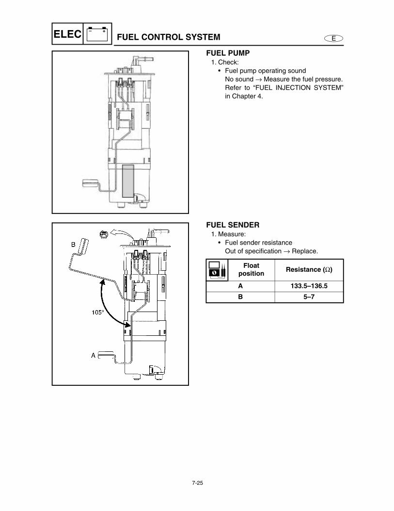
FUEL PUMP1. Check:
• Fuel pump operating sound
No sound → Measure the fuel pressure.
Refer to “FUEL INJECTION SYSTEM”
in Chapter 4.
FUEL SENDER1. Measure:
• Fuel sender resistance
Out of specification → Replace.
Float position
Resistance (Ω)
A 133.5–136.5
B 5–7
Recommended