ELE315 Electronics II
http://www.ee.hacettepe.edu.tr/∼usezen/ele315/
Dr. Umut Sezen & Dr. Dinçer Gökcen
Department of Electrical and Electronic EngineeringHacettepe University
Dr. U. Sezen & Dr. D. Gökcen (Hacettepe Uni.) ELE315 Electronics II 14-Oct-2017 1 / 95
Course Contents
I Analogue Circuits
I Feedback concept and feedback ampliersI Dierential AmpliersI Operational AmpliersI Power AmpliersI Positive feedback and oscillators
I Digital Circuits
I Basic Properties of Digital Integrated CircuitsI BJT Digital Circuits (Ebers & Moll equations, transistor modelling,
state of transistors in a circuit)I Resistor-Transistor Logic (RTL)I Diode-Transistor Logic (DTL)I Transistor-Transistor Logic (TTL)I Dierent TTL GatesI NMOS and CMOS Digital Circuits
Dr. U. Sezen & Dr. D. Gökcen (Hacettepe Uni.) ELE315 Electronics II 14-Oct-2017 2 / 95
Textbook
Analogue Circuits:
1. Sedra and Smith, Microelectronic Circuits, Oxford Press, 2009 (6th ed.)
2. Millman and Grabel, Microelectronics, McGraw-Hill
3. Millman and Halkias, Integrated Electronics, McGraw-Hill
4. Boylestad and Nashelsky, Electronic Devices and Circuit Theory ,Prentice Hall, 8th ed.
Digital Circuits:
1. DeMassa and Ciccone, Digital Integrated Circuits, John Wiley & Sons.
Dr. U. Sezen & Dr. D. Gökcen (Hacettepe Uni.) ELE315 Electronics II 14-Oct-2017 3 / 95
Contents
Feedback and Feedback Ampliers
Amplier ModelsVoltage-Gain AmplierTransresistance AmplierTransconductance AmplierCurrent-Gain Amplier
Negative Feedback ConceptsClosed-loop Gain, Af
Negative Feedback ImprovementsSampling and MixingSampling TypesMixing TypesNegative Feedback Types
Voltage-Series FeedbackNo-load GainInput ResistanceOutput Resistance
Voltage-Shunt FeedbackNo-load GainInput ResistanceOutput Resistance
Current-Series FeedbackNo-load GainInput ResistanceOutput Resistance
Current-Shunt FeedbackNo-load GainInput ResistanceOutput Resistance
Summary of Closed-loop Input and Output Resistances
Analysis of Negative FeedbackRecognize the type of feedbackDerive open-loop circuitEnsure suitability of the input signal sourceObtain open-loop small-signal equivalent circuitFind feedback gain βSummary of feedback amplier analysis
Examples
Dr. U. Sezen & Dr. D. Gökcen (Hacettepe Uni.) ELE315 Electronics II 14-Oct-2017 4 / 95
Feedback and Feedback Ampliers Amplier Models
Amplier Models
Let us rst classify the amplier models according to their input and output signal types.
1. Voltage-Gain Amplier
I voltage input (i.e., voltage source at input)I voltage output (i.e., voltage-controlled voltage source at output)
2. Transresistance Amplier
I current input (i.e., current source at input)I voltage output (i.e., current-controlled voltage source at output)
3. Transconductance Amplier
I voltage input (i.e., voltage source at input)I current output (i.e., voltage-controlled current source at output)
4. Current-Gain Amplier
I current input (i.e., current source at input)I current output (i.e., current-controlled current source at output)
Dr. U. Sezen & Dr. D. Gökcen (Hacettepe Uni.) ELE315 Electronics II 14-Oct-2017 5 / 95
Feedback and Feedback Ampliers Amplier Models
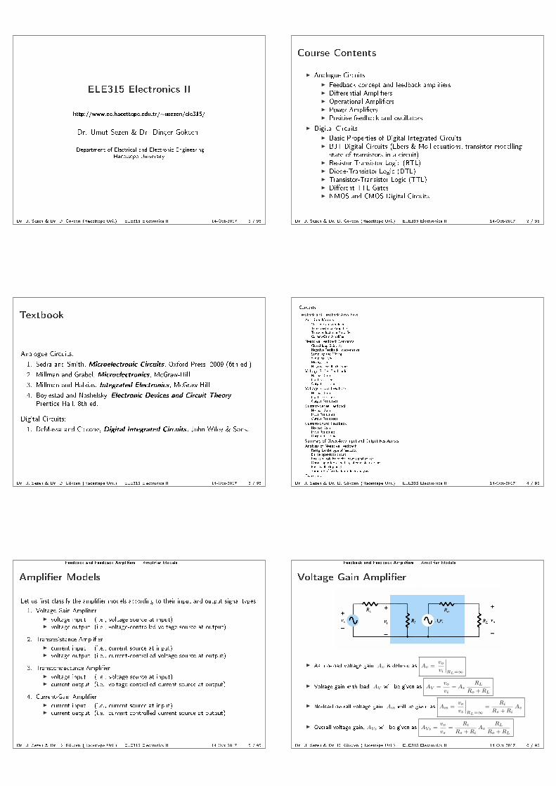
Voltage-Gain Amplier
I As, no-load voltage gain, Av is dened as Av =vo
vi
∣∣∣∣RL=∞
I Voltage gain with load, AV will be given as AV =vo
vi= Av
RL
Ro +RL
I No-load overall voltage gain, Avs will be given as Avs =vo
vs
∣∣∣∣RL=∞
=Ri
Rs +RiAv
I Overall voltage gain, AVs will be given as AVs =vo
vs=
Ri
Rs +RiAv
RL
Ro +RL
Dr. U. Sezen & Dr. D. Gökcen (Hacettepe Uni.) ELE315 Electronics II 14-Oct-2017 6 / 95

Feedback and Feedback Ampliers Amplier Models
I Ideally we want overall voltage gain AVs should be equal to the no-load voltage gain Av .Thus, ideal input resistance Ri and ideal output resistance Ro of a voltage-gain ampliershould be innity and zero, respectively.
AVs → Av ⇒
Ri →∞Ro → 0
I Thus, for a good voltage-gain amplier Ri should be large (i.e., Ri Rs) and Ro shouldbe small (i.e., Ro RL).
Dr. U. Sezen & Dr. D. Gökcen (Hacettepe Uni.) ELE315 Electronics II 14-Oct-2017 7 / 95
Feedback and Feedback Ampliers Amplier Models
Transresistance Amplier
I As, no-load transresistance gain, Rm is dened as Rm =vo
ii
∣∣∣∣RL=∞
I Transresistance gain with load, RM will be given as RM =vo
ii= Rm
RL
Ro +RL
I No-load overall gain, Rms will be given as Rms =vo
is
∣∣∣∣RL=∞
=Rs
Rs +RiRm
I Overall transresistance gain, RMs will be given as RMs =vo
is=
Rs
Rs +RiRm
RL
Ro +RL
Dr. U. Sezen & Dr. D. Gökcen (Hacettepe Uni.) ELE315 Electronics II 14-Oct-2017 8 / 95
Feedback and Feedback Ampliers Amplier Models
I Ideally we want overall transresistance gain RMs should be equal to the no-loadtransresistance gain Rm. Thus, ideal input resistance Ri and ideal output resistance Ro
of a transresistance amplier should be both zero.
RMs → Rm ⇒
Ri → 0
Ro → 0
I Thus, for a good transresistance amplier Ri should be small (i.e., Ri Rs) and Ro
should be small also (i.e., Ro RL).
Dr. U. Sezen & Dr. D. Gökcen (Hacettepe Uni.) ELE315 Electronics II 14-Oct-2017 9 / 95
Feedback and Feedback Ampliers Amplier Models
Transconductance Amplier
I As, no-load transconductance gain, Gm is dened as Gm =io
vi
∣∣∣∣RL=0
I Transconductance gain with load, GM will be given as GM =io
vi= Gm
Ro
Ro + RL
I No-load overall transconductance gain, Gms will be given as Gms =io
vs
∣∣∣∣RL=0
=Ri
Rs + RiGm
I Overall transconductance gain, GMs will be given as GMs =io
vs=
Ri
Rs + RiGm
Ro
Ro + RL
Dr. U. Sezen & Dr. D. Gökcen (Hacettepe Uni.) ELE315 Electronics II 14-Oct-2017 10 / 95
Feedback and Feedback Ampliers Amplier Models
I Ideally we want overall transconductance gain GMs should be equal to the no-loadtransconductance gain Gm. Thus, ideal input resistance Ri and ideal output resistanceRo of a transconductance amplier should be both innity.
GMs → Gm ⇒
Ri →∞Ro →∞
I Thus, for a good transconductance amplier Ri should be large (i.e., Ri Rs) and Ro
should be large also (i.e., Ro RL).
Dr. U. Sezen & Dr. D. Gökcen (Hacettepe Uni.) ELE315 Electronics II 14-Oct-2017 11 / 95
Feedback and Feedback Ampliers Amplier Models
Current-Gain Amplier
I As, no-load current gain, Ai is dened as Ai =io
ii
∣∣∣∣RL=0
I Current gain with load, AI will be given as AI =io
ii= Ai
Ro
Ro +RL
I No-load overall current gain, Ais will be given as Ais =io
is
∣∣∣∣RL=0
=Rs
Rs +RiAi
I Overall current gain, AIs will be given as AIs =io
is=
Rs
Rs +RiAi
Ro
Ro +RL
Dr. U. Sezen & Dr. D. Gökcen (Hacettepe Uni.) ELE315 Electronics II 14-Oct-2017 12 / 95

Feedback and Feedback Ampliers Amplier Models
I Ideally we want overall current gain AIs should be equal to the no-load current gain Ai.Thus, ideal input resistance Ri and ideal output resistance Ro of a current-gain ampliershould be zero and innity, respectively.
AIs → Ai ⇒
Ri → 0
Ro →∞
I Thus, for a good current-gain amplier Ri should be small (i.e., Ri Rs) and Ro
should be large (i.e., Ro RL).
Dr. U. Sezen & Dr. D. Gökcen (Hacettepe Uni.) ELE315 Electronics II 14-Oct-2017 13 / 95
Feedback and Feedback Ampliers Negative Feedback Concepts
Negative Feedback Concepts
The eects of the negative feedback on an amplier can be summarized as follows.
Disadvantages:
I Lower gain
Advantages:
I More stable gainI Reduced distortionI Improved frequency responseI Improved input impedanceI Improved output impedanceI More linear operation
Dr. U. Sezen & Dr. D. Gökcen (Hacettepe Uni.) ELE315 Electronics II 14-Oct-2017 14 / 95
Feedback and Feedback Ampliers Negative Feedback Concepts
Closed-loop Gain, Af
From the gure above we can calculate the closed-loop gain (i.e., gain with feedback), Af =Y
Xas
follows
Y = AXi
Xf = βY
Xi = X −Xf
From the three equations above, we can on obtain the gain with feedback Af as follows
Af =Y
X=
A
1 + βA
If βA 1 then, above equation reduces to Af ≈1
β. So, for Af > 1, β < 1 is required.
Dr. U. Sezen & Dr. D. Gökcen (Hacettepe Uni.) ELE315 Electronics II 14-Oct-2017 15 / 95
Feedback and Feedback Ampliers Negative Feedback Concepts
Negative Feedback Improvements
We are going to investigate and prove the following three improvements of the negativefeedback
1. Improved Gain Stability
2. Reduced Distortion
3. Increased Bandwidth
Dr. U. Sezen & Dr. D. Gökcen (Hacettepe Uni.) ELE315 Electronics II 14-Oct-2017 16 / 95
Feedback and Feedback Ampliers Negative Feedback Concepts
Improved Gain Stability
We need to nd the closed-loop gain stability (relative change of the gain), i.e., the ratio∆Af
Af. In order
to derive this quantity, we need to rst nd the derivativedAf
dA.
dAf
dA=d(
A1+βA
)dA
=1
(1 + βA)2. . . using the chain rule of derivatives
=A
1 + βA
1
A(1 + βA). . .multiplying the numerator and denominator by A
=Af
A
1
1 + βA
From the result above, we can obtain the following expression for the closed-loop gain stability in termsof the open-loop gain stability
dAf
Af=
1
1 + βA
dA
A
Thus, the closed-loop gain stability is improved by a factor of (1 + βA) compared to the open-loop gain
stability.
Dr. U. Sezen & Dr. D. Gökcen (Hacettepe Uni.) ELE315 Electronics II 14-Oct-2017 17 / 95
Feedback and Feedback Ampliers Negative Feedback Concepts
Example 1: Assume a system where open-loop gain equals A = 1000 and changes by20% due to a temperature change. Consider a negative feedback closed-loop system withβ = 0.1 and calculate the change for the closed-loop gain Af for the same conditions.
Solution: We can nd∆Af
Affrom the equation derived previously. Thus,
∆Af
Af=
1
1 + βA
∆A
A
=1
1 + 0.1× 100020%
= 0.2%.
Thus, the closed-loop gain (although smaller) is much more stable than the open-loopgain.
A ↑ ⇒ Y ↑ ⇒ Xf ↑ ⇒ Xi ↓ ⇒ Y ↓
Dr. U. Sezen & Dr. D. Gökcen (Hacettepe Uni.) ELE315 Electronics II 14-Oct-2017 18 / 95
Feedback and Feedback Ampliers Negative Feedback Concepts
Reduced Distortion
Here we are going to assume that we have some additive distortion D in the open-loop system,
Y = AX +D
We need to investigate the same problem when we employ a negative feedback for this system. Let usstart with writing the closed-loop equations from the gure above
Y = AXi +D
Xf = βY
Xi = X −Xf
From the three equations above, we can on obtain the output Y as follows
Y =A
1 + βAX +
D
1 + βA
Thus, distortion in the closed-loop system is reduced by a factor of (1 + βA).
Dr. U. Sezen & Dr. D. Gökcen (Hacettepe Uni.) ELE315 Electronics II 14-Oct-2017 19 / 95
Feedback and Feedback Ampliers Negative Feedback Concepts
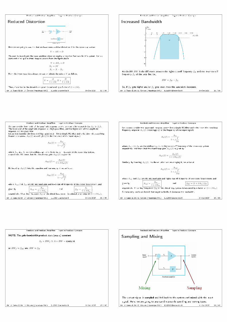
Increased Bandwidth
Bandwidth BW is the dierence between the higher cut-o frequency fH and the lower cut-ofrequency fL of the amplier, i.e.,
BW = fH − fL.
So, if fH gets higher and/or fL gets lower, then the bandwidth increases.
Dr. U. Sezen & Dr. D. Gökcen (Hacettepe Uni.) ELE315 Electronics II 14-Oct-2017 20 / 95
Feedback and Feedback Ampliers Negative Feedback Concepts
We can consider both ends of the amplitude response on the previous slide separately (as fH fL).The lower end of the amplitude response is a high-pass lter, and the higher end of the amplituderesponse is a low-pass lter.Let us rst consider the lower-end high-pass system like a simple RC-lter and write down the open-loopfrequency response AH(f) accordingly (f is the frequency of the input signal)
AH(f) =Am
1− jfL
f
where Am and fL are the midband gain and lower cut-o frequency of the open-loop system,respectively. We know that the closed-loop gain AHf (f) is given by
AHf (f) =AH(f)
1 + βAH(f).
By inserting AH(f) into the equation and rearranging it, we arrive at
AHf (f) =Amf
1− jfLf
f
where Amf and fLf are the midband gain and lower cut-o frequency of the closed-loop system, and
given by Amf =Am
1 + βAmand fLf =
fL
1 + βAm,
respectively. Thus, low-frequency fLf of the closed-loop system is reduced by a factor of (1 + βAm).
Dr. U. Sezen & Dr. D. Gökcen (Hacettepe Uni.) ELE315 Electronics II 14-Oct-2017 21 / 95
Feedback and Feedback Ampliers Negative Feedback Concepts
Let us now consider the upper-end low-pass system like a simple RC-lter and write down the open-loopfrequency response AL(f) accordingly (f is the frequency of the input signal)
AL(f) =Am
1 + jf
fH
where Am and fH are the midband gain and higher cut-o frequency of the open-loop system,respectively. We know that the closed-loop gain ALf (f) is given by
ALf (f) =AL(f)
1 + βAL(f).
Similarly, by inserting AL(f) into the equation and rearranging it, we arrive at
ALf (f) =Amf
1 + jf
fHf
where Amf and fHf are the midband gain and higher cut-o frequency of the closed-loop system, and
given by Amf =Am
1 + βAmand fHf = (1 + βAm) fH ,
respectively. Thus, high-frequency fHf of the closed-loop system is increased by a factor of (1 + βAm).
Consequently, we have showed that negative feedback increases the bandwidth.
Dr. U. Sezen & Dr. D. Gökcen (Hacettepe Uni.) ELE315 Electronics II 14-Oct-2017 22 / 95
Feedback and Feedback Ampliers Negative Feedback Concepts
NOTE: The gain-bandwidth product stays (nearly) constant
Af ×BWf∼= A×BW = constant
as BWf ≈ fHf and BW ≈ fH .
Dr. U. Sezen & Dr. D. Gökcen (Hacettepe Uni.) ELE315 Electronics II 14-Oct-2017 23 / 95
Feedback and Feedback Ampliers Negative Feedback Concepts
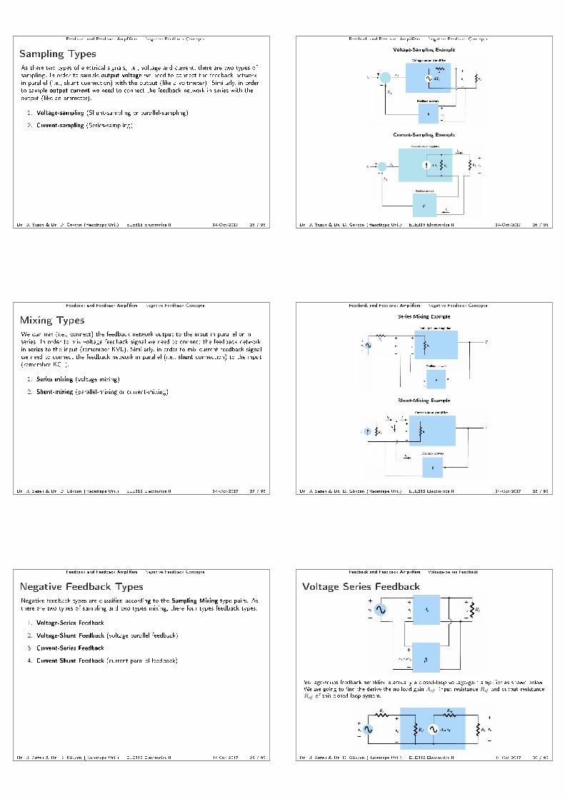
Sampling and Mixing
The output signal is sampled and fed back to the system and mixed with the input
signal. Here, we are going to analyze the possible sampling and mixing types.
Dr. U. Sezen & Dr. D. Gökcen (Hacettepe Uni.) ELE315 Electronics II 14-Oct-2017 24 / 95
Feedback and Feedback Ampliers Negative Feedback Concepts
Sampling Types
As there two types of electrical signals, i.e., voltage and current, there are two types ofsampling. In order to sample output voltage we need to connect the feedback networkin parallel (i.e., shunt connection) with the output (like a voltmeter). Similarly, in orderto sample output current we need to connect the feedback network in series with theoutput (like an ammeter).
1. Voltage-sampling (Shunt-sampling or parallel-sampling)
2. Current-sampling (Series-sampling)
Dr. U. Sezen & Dr. D. Gökcen (Hacettepe Uni.) ELE315 Electronics II 14-Oct-2017 25 / 95
Feedback and Feedback Ampliers Negative Feedback Concepts
Voltage-Sampling Example
Current-Sampling Example
Dr. U. Sezen & Dr. D. Gökcen (Hacettepe Uni.) ELE315 Electronics II 14-Oct-2017 26 / 95
Feedback and Feedback Ampliers Negative Feedback Concepts
Mixing Types
We can mix (i.e., connect) the feedback network output to the input in parallel or inseries. In order to mix voltage feedback signal we need to connect the feedback networkin series to the input (remember KVL). Similarly, in order to mix current feedback signalwe need to connect the feedback network in parallel (i.e., shunt connection) to the input(remember KCL).
1. Series-mixing (voltage-mixing)
2. Shunt-mixing (parallel-mixing or current-mixing)
Dr. U. Sezen & Dr. D. Gökcen (Hacettepe Uni.) ELE315 Electronics II 14-Oct-2017 27 / 95
Feedback and Feedback Ampliers Negative Feedback Concepts
Series-Mixing Example
Shunt-Mixing Example
Dr. U. Sezen & Dr. D. Gökcen (Hacettepe Uni.) ELE315 Electronics II 14-Oct-2017 28 / 95
Feedback and Feedback Ampliers Negative Feedback Concepts
Negative Feedback Types
Negative feedback types are classied according to the Sampling-Mixing type pairs. Asthere are two types of sampling and two types mixing, there four types feedback types.
1. Voltage-Series Feedback
2. Voltage-Shunt Feedback (voltage-parallel feedback)
3. Current-Series Feedback
4. Current-Shunt Feedback (current-parallel feedback)
Dr. U. Sezen & Dr. D. Gökcen (Hacettepe Uni.) ELE315 Electronics II 14-Oct-2017 29 / 95
Feedback and Feedback Ampliers Voltage-Series Feedback
Voltage-Series Feedback
Voltage-series feedback amplier is actually a closed-loop voltage-gain amplier as shown below.We are going to nd the derive the no-load gain Avf , input resistance Rif and output resistanceRof of this closed-loop system.
Dr. U. Sezen & Dr. D. Gökcen (Hacettepe Uni.) ELE315 Electronics II 14-Oct-2017 30 / 95

Feedback and Feedback Ampliers Voltage-Series Feedback
Let us derive no-load gain Avf , input resistance Rif and output resistance Rof of thevoltage-series feedback system in terms of the open-loop amplier parameters Av , Ri and Ro.
Avf =? Rif =? Rof =?
Dr. U. Sezen & Dr. D. Gökcen (Hacettepe Uni.) ELE315 Electronics II 14-Oct-2017 31 / 95
Feedback and Feedback Ampliers Voltage-Series Feedback
Voltage-Series: No-load Gain
From the above gure, we can quickly derive the closed-loop no-load gain Avf where
Avf =vo
vif
∣∣∣∣RL=∞
=vo
vi + vf=
Avvi
(1 + βAv)vi
as
Avf =Av
1 + βAv
Dr. U. Sezen & Dr. D. Gökcen (Hacettepe Uni.) ELE315 Electronics II 14-Oct-2017 32 / 95
Feedback and Feedback Ampliers Voltage-Series Feedback
Voltage-Series: Input Resistance
From the above gure, we can quickly derive the closed-loop input resistance Rif
Rif =vif
ii
∣∣∣∣RL=∞
=vi + vf
ii=
(1 + βAv)vi
ii= (1 + βAv)
vi
ii
as
Rif = (1 + βAv)Ri
Dr. U. Sezen & Dr. D. Gökcen (Hacettepe Uni.) ELE315 Electronics II 14-Oct-2017 33 / 95
Feedback and Feedback Ampliers Voltage-Series Feedback
Loading Eect of Negative Feedback
I If a load RL is connected, then the gain will drop due to the voltage divider conguration betweenRo and RL. Hence, closed-loop input resistance will be aected due to the feedback.
Consequently, closed-loop input resistance Rif will be given by
Rif = (1 + βAV )Ri
where
AV = AvRL
RL + Ro
Dr. U. Sezen & Dr. D. Gökcen (Hacettepe Uni.) ELE315 Electronics II 14-Oct-2017 34 / 95
Feedback and Feedback Ampliers Voltage-Series Feedback
Voltage-Series: Output Resistance
We can calculate the closed-loop output resistance (i.e., as a Thévenin equivalent resistance) by using thetest voltage method as shown in the gure above. Note that as the feedback network is ideal, internalresistance of the feedback network is innity. So, ix = 0 and io = i1 + ix = i1. Also as vif = 0,vi = −vf = −βvo. Hence, output resistance Rof
Rof =vo
io
∣∣∣∣RL=vo,vif=0
=vo
i1=
vovo − Avvi
Ro
=Rovo
vo − Av(−βvo)=
Rovo
(1 + βAv)vo
is derived as
Rof =Ro
1 + βAv
Dr. U. Sezen & Dr. D. Gökcen (Hacettepe Uni.) ELE315 Electronics II 14-Oct-2017 35 / 95
Feedback and Feedback Ampliers Voltage-Series Feedback
Eect of Source Resistance under Negative
Feedback
I If a voltage source vs with an internal resistance Rs is connected at the input, then the gain willdrop due to the voltage divider conguration between Ri and Rs. Hence, closed-loop outputresistance will be aected due to the feedback.
Consequently, closed-loop output resistance Rof will be given by
Rof =Ro
1 + βAvs
where
Avs =Ri
Rs + RiAv
Dr. U. Sezen & Dr. D. Gökcen (Hacettepe Uni.) ELE315 Electronics II 14-Oct-2017 36 / 95

Feedback and Feedback Ampliers Voltage-Shunt Feedback
Voltage-Shunt Feedback
Voltage-shunt feedback amplier is actually a closed-loop transresistance amplier as shownbelow. We are going to nd the derive the no-load gain Rmf , input resistance Rif and outputresistance Rof of this closed-loop system.
Dr. U. Sezen & Dr. D. Gökcen (Hacettepe Uni.) ELE315 Electronics II 14-Oct-2017 37 / 95
Feedback and Feedback Ampliers Voltage-Shunt Feedback
Let us derive no-load gain Rmf , input resistance Rif and output resistance Rof of thevoltage-shunt feedback system in terms of the open-loop amplier parameters Rm, Ri and Ro.
Rmf =? Rif =? Rof =?
Dr. U. Sezen & Dr. D. Gökcen (Hacettepe Uni.) ELE315 Electronics II 14-Oct-2017 38 / 95
Feedback and Feedback Ampliers Voltage-Shunt Feedback
Voltage-Shunt: No-load Gain
From the above gure, we can quickly derive the closed-loop no-load gain Rmf where
Rmf =vo
iif
∣∣∣∣RL=∞
=vo
ii + if=
Rmii
(1 + βRm)ii
as
Rmf =Rm
1 + βRm
Dr. U. Sezen & Dr. D. Gökcen (Hacettepe Uni.) ELE315 Electronics II 14-Oct-2017 39 / 95
Feedback and Feedback Ampliers Voltage-Shunt Feedback
Voltage-Shunt: Input Resistance
From the above gure, we can quickly derive the closed-loop input resistance Rif
Rif =vi
iif
∣∣∣∣RL=∞
=vi
ii + if=
vi
(1 + βRm)ii
as
Rif =Ri
1 + βRm
Dr. U. Sezen & Dr. D. Gökcen (Hacettepe Uni.) ELE315 Electronics II 14-Oct-2017 40 / 95
Feedback and Feedback Ampliers Voltage-Shunt Feedback
Loading Eect of Negative Feedback
I If a load RL is connected, then the gain will drop due to the voltage divider conguration betweenRo and RL. Hence, closed-loop input resistance will be aected due to the feedback.
Consequently, closed-loop input resistance Rif will be given by
Rif =Ri
1 + βRM
where
RM = RmRL
RL + Ro
Dr. U. Sezen & Dr. D. Gökcen (Hacettepe Uni.) ELE315 Electronics II 14-Oct-2017 41 / 95
Feedback and Feedback Ampliers Voltage-Shunt Feedback
Voltage-Shunt: Output Resistance
We can calculate the closed-loop output resistance (i.e., as a Thévenin equivalent resistance) by using thetest voltage method as shown in the gure above. Note that as the feedback network is ideal, internalresistance of the feedback network is innity. So, ix = 0 and io = i1 + ix = i1. Also as iif = 0,ii = −if = −βvo. Hence, output resistance Rof
Rof =vo
io
∣∣∣∣RL=vo,iif=0
=vo
i1=
vovo − Rmii
Ro
=Rovo
vo − Rm(−βvo)=
Rovo
(1 + βRm)vo
is derived as
Rof =Ro
1 + βRm
Dr. U. Sezen & Dr. D. Gökcen (Hacettepe Uni.) ELE315 Electronics II 14-Oct-2017 42 / 95

Feedback and Feedback Ampliers Voltage-Shunt Feedback
Eect of Source Resistance under Negative
Feedback
I If a current source is with an internal resistance Rs is connected at the input, then the gain willdrop due to the current divider conguration between Ri and Rs. Hence, closed-loop outputresistance will be aected due to the feedback.
Consequently, closed-loop output resistance Rof will be given by
Rof =Ro
1 + βRms
where
Rms =Rs
Rs + RiRm
Dr. U. Sezen & Dr. D. Gökcen (Hacettepe Uni.) ELE315 Electronics II 14-Oct-2017 43 / 95
Feedback and Feedback Ampliers Current-Series Feedback
Current-Series Feedback
Current-series feedback amplier is actually a closed-loop transconductance amplier as shownbelow. We are going to nd the derive the no-load gain Gmf , input resistance Rif and outputresistance Rof of this closed-loop system.
Dr. U. Sezen & Dr. D. Gökcen (Hacettepe Uni.) ELE315 Electronics II 14-Oct-2017 44 / 95
Feedback and Feedback Ampliers Current-Series Feedback
Let us derive no-load gain Gmf , input resistance Rif and output resistance Rof of thecurrent-series feedback system in terms of the open-loop amplier parameters Gm, Ri and Ro.
Gmf =? Rif =? Rof =?
Dr. U. Sezen & Dr. D. Gökcen (Hacettepe Uni.) ELE315 Electronics II 14-Oct-2017 45 / 95
Feedback and Feedback Ampliers Current-Series Feedback
Current-Series: No-load Gain
From the above gure, we can quickly derive the closed-loop no-load gain Gmf where
Gmf =io
vif
∣∣∣∣RL=0
=io
vi + vf=
Gmvi
(1 + βGm)vi
as
Gmf =Gm
1 + βGm
Dr. U. Sezen & Dr. D. Gökcen (Hacettepe Uni.) ELE315 Electronics II 14-Oct-2017 46 / 95
Feedback and Feedback Ampliers Current-Series Feedback
Current-Series: Input Resistance
From the above gure, we can quickly derive the closed-loop input resistance Rif
Rif =vif
ii
∣∣∣∣RL=0
=vi + vf
ii=
(1 + βGm)vi
ii= (1 + βGm)
vi
ii
as
Rif = (1 + βGm)Ri
Dr. U. Sezen & Dr. D. Gökcen (Hacettepe Uni.) ELE315 Electronics II 14-Oct-2017 47 / 95
Feedback and Feedback Ampliers Current-Series Feedback
Loading Eect of Negative Feedback
I If a load RL is connected, then the gain will drop due to the current divider conguration betweenRo and RL. Hence, closed-loop input resistance will be aected due to the feedback.
Consequently, closed-loop input resistance Rif will be given by
Rif = (1 + βGM )Ri
where
GM = GmRo
RL + Ro
Dr. U. Sezen & Dr. D. Gökcen (Hacettepe Uni.) ELE315 Electronics II 14-Oct-2017 48 / 95
Feedback and Feedback Ampliers Current-Series Feedback
Current-Series: Output Resistance
We can calculate the closed-loop output resistance (i.e., as a Thévenin equivalent resistance) by using thetest voltage method as shown in the gure above. Note that as the feedback network is ideal, internalresistance of the feedback network is zero. So, vx = 0 and vo = i1Ro + vx = i1Ro. Also as vif = 0,vi = −vf = βio. Hence, output resistance Rof
Rof =vo
io
∣∣∣∣RL=vo,vif=0
=i1Ro
io=
(io +Gmvi)Ro
io=
(io +Gmβio)Ro
io
is derived as
Rof = (1 + βGm)Ro
Dr. U. Sezen & Dr. D. Gökcen (Hacettepe Uni.) ELE315 Electronics II 14-Oct-2017 49 / 95
Feedback and Feedback Ampliers Current-Series Feedback
Eect of Source Resistance under Negative
Feedback
I If a voltage source vs with an internal resistance Rs is connected at the input, then the gain willdrop due to the voltage divider conguration between Ri and Rs. Hence, closed-loop outputresistance will be aected due to the feedback.
Consequently, closed-loop output resistance Rof will be given by
Rof = (1 + βGms)Ro
where
Gms =Ri
Rs + RiGm
Dr. U. Sezen & Dr. D. Gökcen (Hacettepe Uni.) ELE315 Electronics II 14-Oct-2017 50 / 95
Feedback and Feedback Ampliers Current-Shunt Feedback
Current-Shunt Feedback
Current-shunt feedback amplier is actually a closed-loop current-gain amplier as shown below.We are going to nd the derive the no-load gain Aif , input resistance Rif and output resistanceRof of this closed-loop system.
Dr. U. Sezen & Dr. D. Gökcen (Hacettepe Uni.) ELE315 Electronics II 14-Oct-2017 51 / 95
Feedback and Feedback Ampliers Current-Shunt Feedback
Let us derive no-load gain Aif , input resistance Rif and output resistance Rof of thecurrent-shunt feedback system in terms of the open-loop amplier parameters Ai, Ri and Ro.
Aif =? Rif =? Rof =?
Dr. U. Sezen & Dr. D. Gökcen (Hacettepe Uni.) ELE315 Electronics II 14-Oct-2017 52 / 95
Feedback and Feedback Ampliers Current-Shunt Feedback
Current-Shunt: No-load Gain
From the above gure, we can quickly derive the closed-loop no-load gain Aif where
Aif =io
iif
∣∣∣∣RL=0
=io
ii + if=
Aiii
(1 + βAi)ii
as
Aif =Ai
1 + βAi
Dr. U. Sezen & Dr. D. Gökcen (Hacettepe Uni.) ELE315 Electronics II 14-Oct-2017 53 / 95
Feedback and Feedback Ampliers Current-Shunt Feedback
Current-Shunt: Input Resistance
From the above gure, we can quickly derive the closed-loop input resistance Rif
Rif =vi
iif
∣∣∣∣RL=0
=vi
ii + if=
vi
(1 + βAi)ii
as
Rif =Ri
1 + βAi
Dr. U. Sezen & Dr. D. Gökcen (Hacettepe Uni.) ELE315 Electronics II 14-Oct-2017 54 / 95

Feedback and Feedback Ampliers Current-Shunt Feedback
Loading Eect of Negative Feedback
I If a load RL is connected, then the gain will drop due to the current divider conguration betweenRo and RL. Hence, closed-loop input resistance will be aected due to the feedback.
Consequently, closed-loop input resistance Rif will be given by
Rif =Ri
1 + βAI
where
AI = AiRo
RL + Ro
Dr. U. Sezen & Dr. D. Gökcen (Hacettepe Uni.) ELE315 Electronics II 14-Oct-2017 55 / 95
Feedback and Feedback Ampliers Current-Shunt Feedback
Current-Shunt: Output Resistance
We can calculate the closed-loop output resistance (i.e., as a Thévenin equivalent resistance) by using thetest voltage method as shown in the gure above. Note that as the feedback network is ideal, internalresistance of the feedback network is zero. So, vx = 0 and vo = i1Ro + vx = i1Ro. Also as iif = 0,ii = −if = βio. Hence, output resistance Rof
Rof =vo
io
∣∣∣∣RL=vo,iif=0
=i1Ro
io=
(io + Aiii)Ro
io=
(io + Aiβio)Ro
io
is derived as
Rof = (1 + βAi)Ro
Dr. U. Sezen & Dr. D. Gökcen (Hacettepe Uni.) ELE315 Electronics II 14-Oct-2017 56 / 95
Feedback and Feedback Ampliers Current-Shunt Feedback
Eect of Source Resistance under Negative
Feedback
I If a current source is with an internal resistance Rs is connected at the input, then the gain willdrop due to the current divider conguration between Ri and Rs. Hence, closed-loop outputresistance will be aected due to the feedback.
Consequently, closed-loop output resistance Rof will be given by
Rof = (1 + βAis)Ro
where
Ais =Rs
Rs + RiAi
Dr. U. Sezen & Dr. D. Gökcen (Hacettepe Uni.) ELE315 Electronics II 14-Oct-2017 57 / 95
Feedback and Feedback Ampliers Summary of Closed-loop Input and Output Resistances
Summary of Closed-loop Input and Output
Resistances
Table below summarizes the closed-loop input and output resistances for each type of feedback.
Dr. U. Sezen & Dr. D. Gökcen (Hacettepe Uni.) ELE315 Electronics II 14-Oct-2017 58 / 95
Feedback and Feedback Ampliers Analysis of Negative Feedback
Analysis of Negative Feedback
The following steps needs to be taken during the analysis of negative feedback.
1. Recognize the type of feedback
2. Derive open-loop circuit (i.e., circuit without feedback)
3. Ensure suitability of the input signal source
4. Obtain open-loop small-signal equivalent circuit
5. Find feedback gain β = Xf/Y
6. Calculate open-loop parameters A, Ri and Ro
7. Calculate closed-loop parameters Af , Rif and Rof
Dr. U. Sezen & Dr. D. Gökcen (Hacettepe Uni.) ELE315 Electronics II 14-Oct-2017 59 / 95
Feedback and Feedback Ampliers Analysis of Negative Feedback
Recognize the type of feedback
a) Identify the common circuit elements (i.e., feedback network) in between the inputand output loops.
b) Determine input-mixing type (i.e., type of feedback signal Xf )
Series-mixing (feedback signal is voltage, vf )
If the input voltage source vs is connected to the output with anelement in series
- e.g., when a circuit element, like RE or RS , present in theemitter/source terminal of the rst transistor when the input isfrom the base/gate terminal.
Shunt-mixing (feedback signal is current, if )
If the output-circuit is wired to the input circuit allowing the feedbackcurrent if to ow
- e.g., collector-feedback conguration or drain-feedbackconguration
Dr. U. Sezen & Dr. D. Gökcen (Hacettepe Uni.) ELE315 Electronics II 14-Oct-2017 60 / 95

Feedback and Feedback Ampliers Analysis of Negative Feedback
c) Determine output-sampling type
Voltage-sampling (shunt-connection)
If Xf = 0 when vo = 0V (i.e., RL = 0 Ω)
Current-sampling (series-connection)
If Xf = 0 when io = 0A (i.e., RL = ∞Ω)
NOTE 1: If both tests hold, then select the one where feedback gain β doesnot contain the load (or eective load) in its expression.
NOTE 2: If the feedback network is connected in parallel to the output, thenit is voltage-sampling. Similarly, if the feedback network is connected inseries to the output, then it is current-sampling
Dr. U. Sezen & Dr. D. Gökcen (Hacettepe Uni.) ELE315 Electronics II 14-Oct-2017 61 / 95
Feedback and Feedback Ampliers Analysis of Negative Feedback
Derive open-loop circuit
a) Obtain the open-loop input circuitry
Voltage-sampling
Make Xf = 0 by making vo = 0, i.e., short-circuit the output connection.
Dr. U. Sezen & Dr. D. Gökcen (Hacettepe Uni.) ELE315 Electronics II 14-Oct-2017 62 / 95
Feedback and Feedback Ampliers Analysis of Negative Feedback
Current-sampling
Make Xf = 0 by making io = 0, i.e., open-circuit the output connection.
Dr. U. Sezen & Dr. D. Gökcen (Hacettepe Uni.) ELE315 Electronics II 14-Oct-2017 63 / 95
Feedback and Feedback Ampliers Analysis of Negative Feedback
b) Obtain the open-loop output circuitry
Series-mixing
Make the reverse feedback signal Yf = 0 by making ii = 0 whereYf = βrii and βr is the reverse feedback gain, i.e., open-circuit the inputconnection.
Dr. U. Sezen & Dr. D. Gökcen (Hacettepe Uni.) ELE315 Electronics II 14-Oct-2017 64 / 95
Feedback and Feedback Ampliers Analysis of Negative Feedback
Shunt-mixing
Make the reverse feedback signal Yf = 0 by making vi = 0 whereYf = βrvi and βr is the reverse feedback gain, i.e., short-circuit the inputconnection.
Dr. U. Sezen & Dr. D. Gökcen (Hacettepe Uni.) ELE315 Electronics II 14-Oct-2017 65 / 95
Feedback and Feedback Ampliers Analysis of Negative Feedback
NOTE: According to the connection type, always short-circuit a shunt-connection(or parallel-connection) and always open-circuit a series-connection in order toeliminate the eect of the observable. This is true for both output and inputconnections of the feedback network.
Dr. U. Sezen & Dr. D. Gökcen (Hacettepe Uni.) ELE315 Electronics II 14-Oct-2017 66 / 95

Feedback and Feedback Ampliers Analysis of Negative Feedback
c) Then draw the open-loop circuit by putting the input circuitry and output circuitrytogether
i. Open-loop circuit diagram for voltage-series feedback
ii. Open-loop circuit diagram for voltage-shunt feedback
Dr. U. Sezen & Dr. D. Gökcen (Hacettepe Uni.) ELE315 Electronics II 14-Oct-2017 67 / 95
Feedback and Feedback Ampliers Analysis of Negative Feedback
iii. Open-loop circuit diagram for current-series feedback
iv. Open-loop circuit diagram for current-shunt feedback
Dr. U. Sezen & Dr. D. Gökcen (Hacettepe Uni.) ELE315 Electronics II 14-Oct-2017 68 / 95
Feedback and Feedback Ampliers Analysis of Negative Feedback
Ensure suitability of the input signal source
If feedback signal Xf is a
Voltage signal (in the case of series-mixing)
Use a Thévenin voltage source,
Current signal (in the case of shunt-mixing)
Use a Norton current source.
NOTE: If necessary, perform source transformation (voltage source ↔ currentsource).
Dr. U. Sezen & Dr. D. Gökcen (Hacettepe Uni.) ELE315 Electronics II 14-Oct-2017 69 / 95
Feedback and Feedback Ampliers Analysis of Negative Feedback
Obtain open-loop small-signal equivalent circuit
Replace each active device (e.g. BJT, JFET, MOSFET etc.) in the open-loopcircuit by their appropriate small-signal model and draw the open-loop small signalequivalent circuit.
Dr. U. Sezen & Dr. D. Gökcen (Hacettepe Uni.) ELE315 Electronics II 14-Oct-2017 70 / 95
Feedback and Feedback Ampliers Analysis of Negative Feedback
Find feedback gain β
I Obtain feedback gain β =Xf
YFeedback circuit cannot include either the source resistance Rs or the loadresistance RL.
i.e., β 6= β(Rs, RL), in other words, β cannot be a function of Rs orRL.
NOTE: Any external circuit element (or equivalent element) via which we obtainthe output voltage vo and output current io will be the eective load in thecircuit, even though it was not labelled explicitly as RL.
Dr. U. Sezen & Dr. D. Gökcen (Hacettepe Uni.) ELE315 Electronics II 14-Oct-2017 71 / 95
Feedback and Feedback Ampliers Analysis of Negative Feedback
Summary of feedback analysis
The table below shows the summary of the feedback amplier analysis
Dr. U. Sezen & Dr. D. Gökcen (Hacettepe Uni.) ELE315 Electronics II 14-Oct-2017 72 / 95
Feedback and Feedback Ampliers Examples
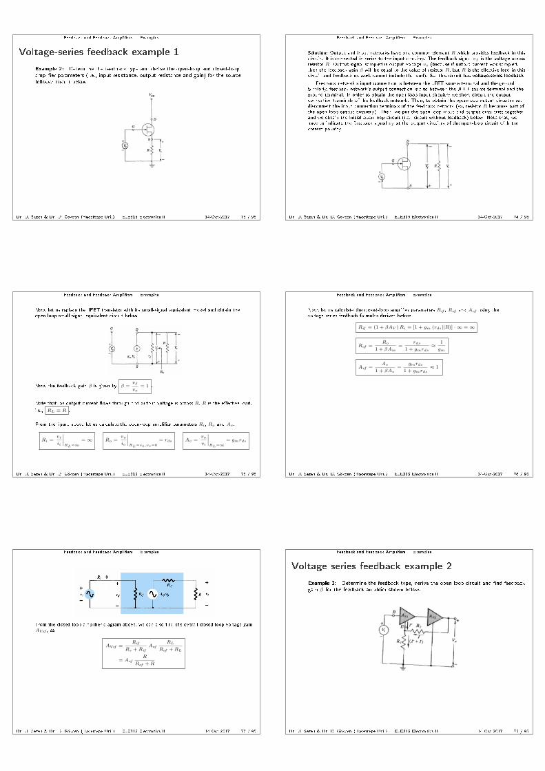
Voltage-series feedback example 1
Example 2: Determine the feedback type and derive the open-loop and closed-loopamplier parameters (i.e., input resistance, output resistance and gain) for the sourcefollower circuit below.
Dr. U. Sezen & Dr. D. Gökcen (Hacettepe Uni.) ELE315 Electronics II 14-Oct-2017 73 / 95
Feedback and Feedback Ampliers Examples
Solution: Output and input networks have one common element R which provides feedback in thiscircuit. It is connected in series to the input circuitry. The feedback signal vf is the voltage acrossresistor R. Output signal sampled is output voltage vo (because if output current was sampled,then the feedback gain β will be equal to the value of resistor R, but R is the eective load in thiscircuit and feedback network cannot include the load). So, this circuit has voltage-series feedback.
Feedback network's input connection is between the JFET source terminal and the ground.Similarly, feedback network's output connection is also between the JFET source terminal and theground terminal. In order to obtain the open-loop input circuitry we short circuit the outputconnection terminals of the feedback network. Then, to obtain the open-loop output circuitry wedisconnect the input connection terminals of the feedback network (so, resistor R becomes part ofthe open-loop output circuitry). Then, we put the open-loop input and output circuitries togetherand we obtain the initial open-loop circuit (i.e., circuit without feedback) below. Note that, wehave to indicate the feedback signal vf at the output circuitry of the open-loop circuit with thecorrect polarity.
Dr. U. Sezen & Dr. D. Gökcen (Hacettepe Uni.) ELE315 Electronics II 14-Oct-2017 74 / 95
Feedback and Feedback Ampliers Examples
Now, let us replace the JFET transistor with its small-signal equivalent model and obtain theopen-loop small-signal equivalent circuit below
Now, the feedback gain β is given by β =vf
vo= 1 .
Note that, as output current ows through and output voltage is across R, R is the eective load,
i.e., RL ≡ R .
From the gure above let us calculate the open-loop amplier parameters Ri, Ro and Av .
Ri =vi
ii
∣∣∣∣RL=∞
=∞ Ro =vo
io
∣∣∣∣RL=vo,vs=0
= rds Av =vo
vi
∣∣∣∣RL=∞
= gmrds
Dr. U. Sezen & Dr. D. Gökcen (Hacettepe Uni.) ELE315 Electronics II 14-Oct-2017 75 / 95
Feedback and Feedback Ampliers Examples
Now, let us calculate the closed-loop amplier parameters Rif , Rof and Avf using thevoltage-series feedback formulas derived before.
Rif = (1 + βAV )Ri = [1 + gm (rds||R)] · ∞ =∞
Rof =Ro
1 + βAvs=
rds
1 + gmrds≈
1
gm
Avf =Av
1 + βAv=
gmrds
1 + gmrds≈ 1
Dr. U. Sezen & Dr. D. Gökcen (Hacettepe Uni.) ELE315 Electronics II 14-Oct-2017 76 / 95
Feedback and Feedback Ampliers Examples
From the closed-loop amplier diagram above, we can also nd the overall closed-loop voltage gainAVsf , as
AVsf =Rif
Rs + RifAvf
RL
Rof + RL
= AvfR
Rof + R
Dr. U. Sezen & Dr. D. Gökcen (Hacettepe Uni.) ELE315 Electronics II 14-Oct-2017 77 / 95
Feedback and Feedback Ampliers Examples
Voltage-series feedback example 2
Example 3: Determine the feedback type, derive the open-loop circuit and nd feedbackgain β for the feedback amplier shown below.
Dr. U. Sezen & Dr. D. Gökcen (Hacettepe Uni.) ELE315 Electronics II 14-Oct-2017 78 / 95

Feedback and Feedback Ampliers Examples
Solution: Feedback type is voltage-series feedback and feedback network, consisting ofresistors R1 and R2, connects the output and input networks to each other.Consequently, open-loop circuit is derived as shown below
Thus, feedback gain β is found as β =vf
vo=
R1
R1 +R2.
Dr. U. Sezen & Dr. D. Gökcen (Hacettepe Uni.) ELE315 Electronics II 14-Oct-2017 79 / 95
Feedback and Feedback Ampliers Examples
Voltage-shunt feedback example
Example 4: Determine the feedback type and derive the open-loop and closed-loopamplier parameters (i.e., input resistance, output resistance and gain) for the collectorfeedback circuit below.
Dr. U. Sezen & Dr. D. Gökcen (Hacettepe Uni.) ELE315 Electronics II 14-Oct-2017 80 / 95
Feedback and Feedback Ampliers Examples
Solution: Output and input network have one common element R′ which provides feedback in thiscircuit. It is connected in parallel (i.e., shunt connection) to the input circuitry. The feedbacksignal if is the current through resistor R′. Output signal sampled is output voltage vo. So, thiscircuit has voltage-shunt feedback.
Feedback network's input connection is between the BJT base terminal and the ground.Similarly, feedback network's output connection is between the BJT collector terminal and theground. In order to obtain the open-loop input circuitry, we short circuit the output connectionterminals of the feedback network. Then, to obtain the open-loop output circuitry we short circuitthe input connection terminals of the feedback network. Then, we put the open-loop input andoutput circuitries together and we obtain the initial open-loop circuit (i.e., circuit withoutfeedback) below. Note that, we have transformed the input voltage source to a current source asfeedback signal is a current signal and also indicated the feedback signal if at the output circuitryof the open-loop circuit with the correct direction.
Dr. U. Sezen & Dr. D. Gökcen (Hacettepe Uni.) ELE315 Electronics II 14-Oct-2017 81 / 95
Feedback and Feedback Ampliers Examples
Now, the feedback gain β is given by β =if
vo=
if
−ifR′ = −1
R′ .
Note that, as output current ows through and output voltage is across RC , RC is the eective
load, i.e., RL ≡ RC .
From the gure above let us calculate the open-loop amplier parameters Ri, Ro and Rm.
Ri =vi
ii
∣∣∣∣RL=∞
= R′||hie Ro =
vo
io
∣∣∣∣RL=vo,is=0
= R′||
1
hoe
Rm =vo
ii
∣∣∣∣RL=∞
= −hfe(R
′||1
hoe
)R′
R′ + hie
Dr. U. Sezen & Dr. D. Gökcen (Hacettepe Uni.) ELE315 Electronics II 14-Oct-2017 82 / 95
Feedback and Feedback Ampliers Examples
Now, let us calculate the closed-loop amplier parameters Rif , Rof and Rmf using thevoltage-shunt feedback formulas derived before.
Rif =Ri
1 + βRM=
R′||hie
1 + (R′||1/hoe)hfe
R′ + hie
RC
(R′||1/hoe) + RC
≈hie
1 + hfeRC
R′
Rof =Ro
1 + βRms=
R′||1/hoe
1 +Rs
Rs + Ri(R′||1/hoe)
hfe
R′ + hie
≈(
1 +Ri
Rs
)R′
hfe
Rmf =Rm
1 + βRm=
−(R′||1/hoe
) hfeR′
R′ + hie
1 + (R′||1/hoe)hfe
R′ + hie
≈ −R′
Dr. U. Sezen & Dr. D. Gökcen (Hacettepe Uni.) ELE315 Electronics II 14-Oct-2017 83 / 95
Feedback and Feedback Ampliers Examples
From the closed-loop amplier diagram above, we can also nd the overall closed-looptransresistance gain RMsf , as
RMsf =vo
is=
Rs
Rs + RifRmf
RC
Rof + RC
where is =vs
Rs
Thus, overall closed-loop voltage gain AVsf will be given by
AVsf =vo
vs=
vo
isRs=
1
RsRMsf
Dr. U. Sezen & Dr. D. Gökcen (Hacettepe Uni.) ELE315 Electronics II 14-Oct-2017 84 / 95

Feedback and Feedback Ampliers Examples
Current-series feedback example
Example 5: Determine the feedback type and derive the open-loop and closed-loopamplier parameters (i.e., input resistance, output resistance and gain) for the commonemitter circuit below.
Dr. U. Sezen & Dr. D. Gökcen (Hacettepe Uni.) ELE315 Electronics II 14-Oct-2017 85 / 95
Feedback and Feedback Ampliers Examples
Solution: Output and input networks have one common element RE which provides feedback inthis circuit. It is connected in series to the input circuitry. The feedback signal vf is the voltageacross resistor RE . Output signal sampled is output current io. So, this circuit has current-seriesfeedback.
Feedback network's input connection is between the BJT emitter terminal and the ground.Similarly, feedback network's output connection is also between the BJT emitter terminal and theground. In order to obtain the open-loop input circuitry, we disconnect the output connectionterminals of the feedback network. Then, to obtain the open-loop output circuitry we alsodisconnect the input connection terminals of the feedback network. Then, we put the open-loopinput and output circuitries together and we obtain the initial open-loop circuit (i.e., circuitwithout feedback) below. Note that, have to indicate the feedback signal vf at the outputcircuitry of the open-loop circuit with the correct polarity.
Dr. U. Sezen & Dr. D. Gökcen (Hacettepe Uni.) ELE315 Electronics II 14-Oct-2017 86 / 95
Feedback and Feedback Ampliers Examples
Now, let us replace the BJT transistor with its small-signal equivalent model and obtain theopen-loop small-signal equivalent circuit below
Now, the feedback gain β is given by β =vf
io=−REioio
= −RE .
Note that, as output current ows through and output voltage is across RL, RL is the eectiveload.
From the gure above let us calculate the open-loop amplier parameters Ri, Ro and Gm.
Ri =vi
ii
∣∣∣∣RL=0
= RE + hie Ro =vo
io
∣∣∣∣RL=vo,vs=0
= 1/hoe + RE
Gm =io
vi
∣∣∣∣RL=0
= −1/hoe
1/hoe + RE
hfe
RE + hie
≈−hfe
RE + hie
Dr. U. Sezen & Dr. D. Gökcen (Hacettepe Uni.) ELE315 Electronics II 14-Oct-2017 87 / 95
Feedback and Feedback Ampliers Examples
Now, let us calculate the closed-loop amplier parameters Rif , Rof and Gmf using thecurrent-series feedback formulas derived before.
Rif = (1 + βGM )Ri =
(1 +
hfeRE
RE + hie
1/hoe + RE
1/hoe + RE + RL
)(RE + hie)
≈ (hfe + 1)RE + hie
Rof = (1 + βGms)Ro =
(1 +
RE + hie
Rs + RE + hie
hfeRE
RE + hie
)(1/hoe + RE) ≈ ∞
Gmf =Gm
1 + βGm=
−hfeRE + hie
1 +hfeRE
RE + hie
≈ −1
RE
Dr. U. Sezen & Dr. D. Gökcen (Hacettepe Uni.) ELE315 Electronics II 14-Oct-2017 88 / 95
Feedback and Feedback Ampliers Examples
From the closed-loop amplier diagram above, we can also nd the overall closed-looptransconductance gain GMsf , as
GMsf =io
vs=
Rif
Rs + RifGmf
Rof
Rof + RL
Thus, overall closed-loop voltage gain AVsf will be given by
AVsf =vo
vs=ioRL
vs= GMsfRL
Dr. U. Sezen & Dr. D. Gökcen (Hacettepe Uni.) ELE315 Electronics II 14-Oct-2017 89 / 95
Feedback and Feedback Ampliers Examples
Current-shunt feedback example
Example 6: Determine the feedback type and derive the open-loop and closed-loopamplier parameters (i.e., input resistance, output resistance and gain) for the multistageBJT circuit below.
Dr. U. Sezen & Dr. D. Gökcen (Hacettepe Uni.) ELE315 Electronics II 14-Oct-2017 90 / 95

Feedback and Feedback Ampliers Examples
Solution: Output and input networks have two common elements R′ and RE which providefeedback in this circuit. It is connected in parallel (i.e., shunt connection) to the input circuitry.The feedback signal if is the voltage through resistor R′. Output signal sampled is output currentio. So, this circuit has current-shunt feedback.
Feedback network's input connection is between the base terminal of Q1 and the ground.Similarly, feedback network's output connection is between the emitter terminal of Q2 and theground. In order to obtain the open-loop input circuitry, we disconnect the output connectionterminals of the feedback network. Then, to obtain the open-loop output circuitry we short circuitthe input connection terminals of the feedback network. Then, we put the open-loop input andoutput circuitries together and we obtain the initial open-loop circuit (i.e., circuit withoutfeedback) below. Note that, have to indicate the feedback signal if at the output circuitry of theopen-loop circuit with the correct direction.
Dr. U. Sezen & Dr. D. Gökcen (Hacettepe Uni.) ELE315 Electronics II 14-Oct-2017 91 / 95
Feedback and Feedback Ampliers Examples
Now, the feedback gain β is given by β =if
io=
RE
R′ + RE.
Note that, as output current ows through and output voltage is across RC2, RC2 is the eective
load, i.e., RL ≡ RC2 .
From the gure above let us calculate the open-loop amplier parameters Ri, Ro and Ai. Notethat, for simplicity we take hoe1 = hoe2 = 0.
Ri =vi
ii
∣∣∣∣RL=0
= (R′+ RE)||hie1 Ro =
vo
io
∣∣∣∣RL=vo,is=0
=∞
Dr. U. Sezen & Dr. D. Gökcen (Hacettepe Uni.) ELE315 Electronics II 14-Oct-2017 92 / 95
Feedback and Feedback Ampliers Examples
Before calculating the total gain Ai, let us rst calculate no-load gain of the second stage Ai2 andloaded gain of the rst stage AI1 as follows
Ai2 =io
ii2
∣∣∣∣∣RL=0
=io
ib2= −hfe2
Note that io1 = ii2 = ib2 .
AI1 =io1ii
=ib2ii
= −RE + R′
RE + R′ + hie1hfe1
RC1
RC1 + Ri2
where Ri2 is the input resistance of the second stage and given by
Ri2 = hie2 +(hfe2+1
) (R
′||RE)
Thus, open-loop no-load current gain Ai is given by
Ai =io
ii
∣∣∣∣RL=0
= AI1 · Ai2 =RE + R′
RE + R′ + hie1
hfe1hfe2RC1
RC1 + Ri2
Dr. U. Sezen & Dr. D. Gökcen (Hacettepe Uni.) ELE315 Electronics II 14-Oct-2017 93 / 95
Feedback and Feedback Ampliers Examples
Now, let us calculate the closed-loop amplier parameters Rif , Rof and Aif using thecurrent-series feedback formulas derived before.
Rif =Ri
1 + βAI=
(R′ + RE)||hie1
1 +RE
RE + R′ + hie1
hfe1hfe2RC1
RC1 + Ri2
Rof = (1 + βAis)Ro =
(1 +
Rs
Rs + Ri
RE
R′ + REAi
)∞ =∞
Aif =Ai
1 + βAi=
RE + R′
RE + R′ + hie1
hfe1hfe2RC1
RC1 + Ri2
1 +RE
RE + R′ + hie1
hfe1hfe2RC1
RC1 + Ri2
≈ 1 +R′
RE
Dr. U. Sezen & Dr. D. Gökcen (Hacettepe Uni.) ELE315 Electronics II 14-Oct-2017 94 / 95
Feedback and Feedback Ampliers Examples
From the closed-loop amplier diagram above, we can also nd the overall closed-loop current gainAIsf , as
AIsf =io
is=
Rs
Rs + RifAif
Rof
Rof + RC2
where is =vs
Rs
Thus, overall closed-loop voltage gain AVsf will be given by
AVsf =vo
vs=ioRC2
isRs=RC2
RsAIsf
Dr. U. Sezen & Dr. D. Gökcen (Hacettepe Uni.) ELE315 Electronics II 14-Oct-2017 95 / 95
Recommended