1
EE302 Lesson 13:Antenna Fundamentals
An antenna is a device that provides a transition between guided electromagnetic waves in wires and electromagnetic waves in free space.
Antennas
2
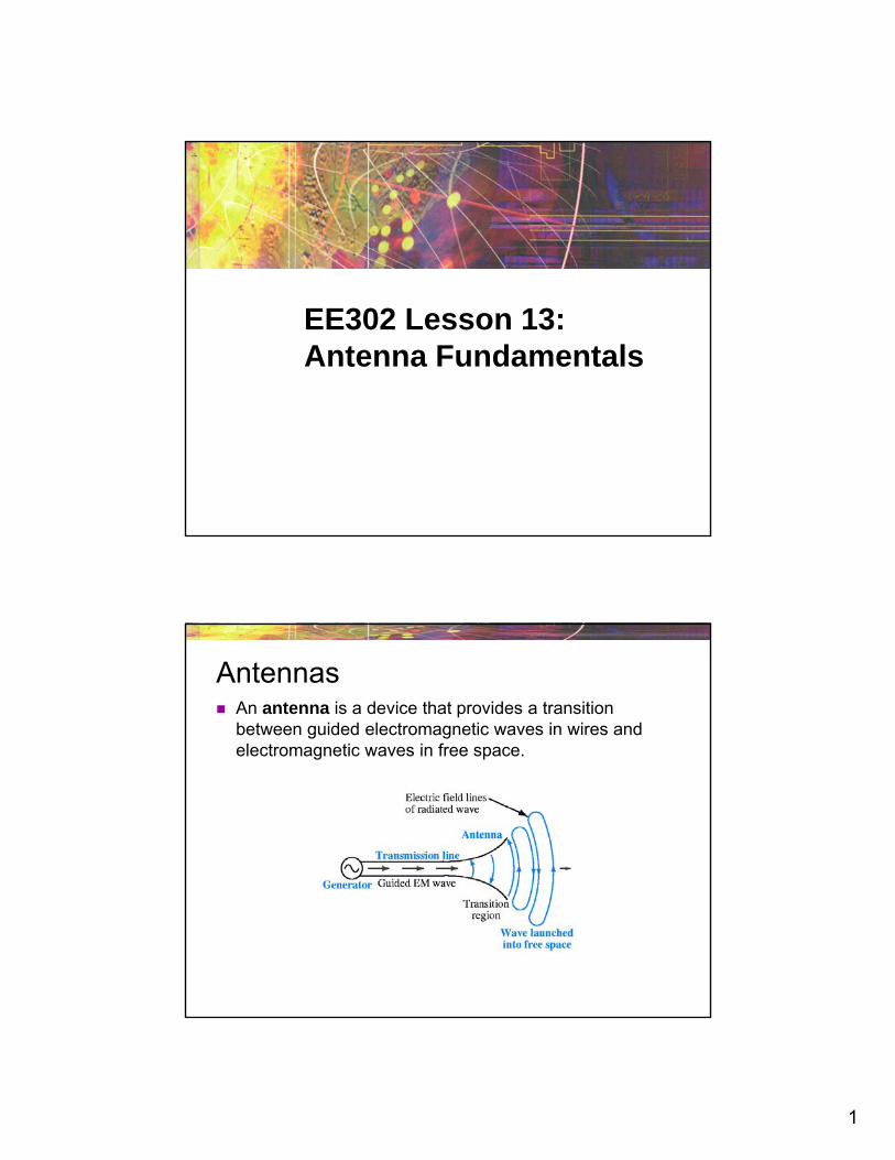
Antennas can usually handle this transition in both directions (transmitting and receiving EM waves). This property is called reciprocity.
Reciprocity
The antenna’s size and shape largely determines the frequencies it can handle and how it radiates electromagnetic waves.
Antenna physical characteristics
3
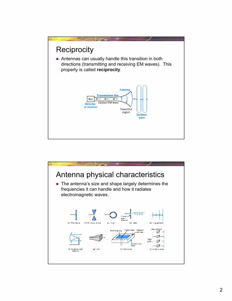
The polarization of an antenna refers to the orientation of the electric field it produces.
Polarization is important because the receiving antenna should have the same polarization as the transmitting antenna to maximize received power.
Antenna polarization
Antenna polarization Horizontal Polarization Vertical Polarization Circular Polarization
Electric and magnetic field rotate at the frequency of the transmitter
Used when the orientation of the receiving antenna is unknown Will work for both vertical and horizontal antennas
Right Hand Circular Polarization (RHCP) Left Hand Circular Polarization (LHCP)
Both antennas must be the same orientation (RHCP or LHCP)
4
You may recall from physics that wavelength () and frequency (f ) of an electromagnetic wave in free space are related by the speed of light (c)
Therefore, if a radio station is broadcasting at a frequency of 100 MHz, the wavelength of its signal is given
Wavelength ()
c
c ff
or
8
6
3.0 10 m/s3 m
100 10 cycle/s
c
f
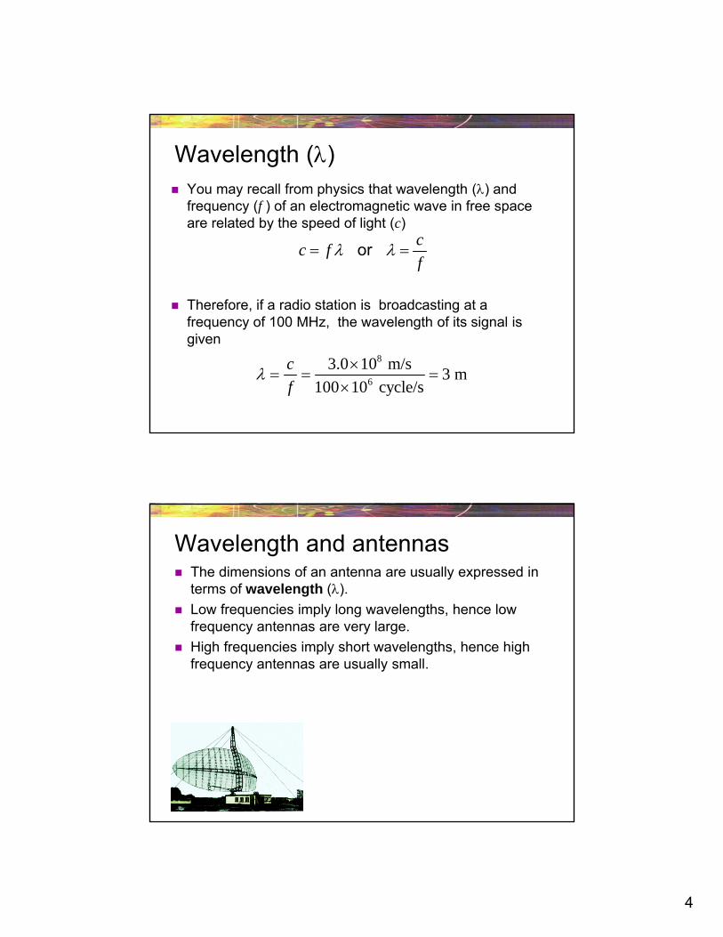
The dimensions of an antenna are usually expressed in terms of wavelength ().
Low frequencies imply long wavelengths, hence low frequency antennas are very large.
High frequencies imply short wavelengths, hence high frequency antennas are usually small.
Wavelength and antennas
5
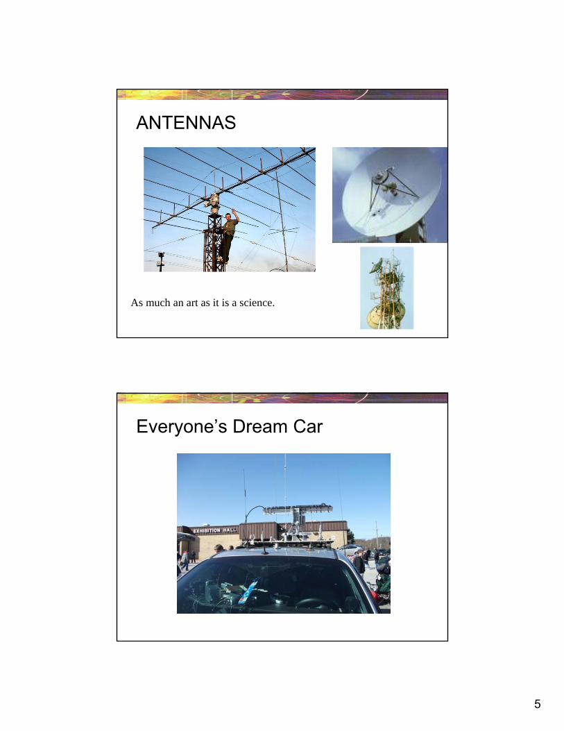
ANTENNAS
As much an art as it is a science.
Everyone’s Dream Car
6
What to look for in Antennas
Freq/Wavelength
Beam Pattern
Bandwidth
Gain
Basic Antenna
An antenna can be a length of wire, a metal rod, or a piece of metal tubing.
Antennas radiate most effectively when their length is directly related to the wavelength of the transmitted signal.
Most antennas have a length that is some fraction of a wavelength.
One-half and one-quarter wavelengths are most common.
7
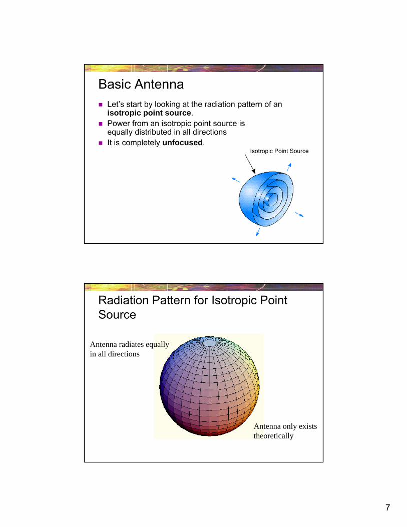
Basic Antenna Let’s start by looking at the radiation pattern of an
isotropic point source. Power from an isotropic point source is
equally distributed in all directions It is completely unfocused.
Isotropic Point Source
Radiation Pattern for Isotropic Point Source
Antenna radiates equallyin all directions
Antenna only existstheoretically
8
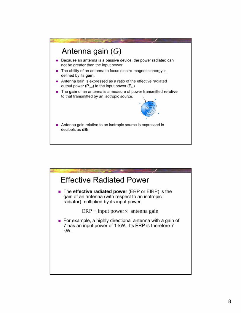
Antenna gain (G) Because an antenna is a passive device, the power radiated can
not be greater than the input power.
The ability of an antenna to focus electro-magnetic energy is defined by its gain.
Antenna gain is expressed as a ratio of the effective radiated output power (Pout) to the input power (Pin)
The gain of an antenna is a measure of power transmitted relativeto that transmitted by an isotropic source.
Antenna gain relative to an isotropic source is expressed in decibels as dBi.
Effective Radiated Power The effective radiated power (ERP or EIRP) is the
gain of an antenna (with respect to an isotropic radiator) multiplied by its input power.
For example, a highly directional antenna with a gain of 7 has an input power of 1-kW. Its ERP is therefore 7 kW.
ERP input power antenna gain
9
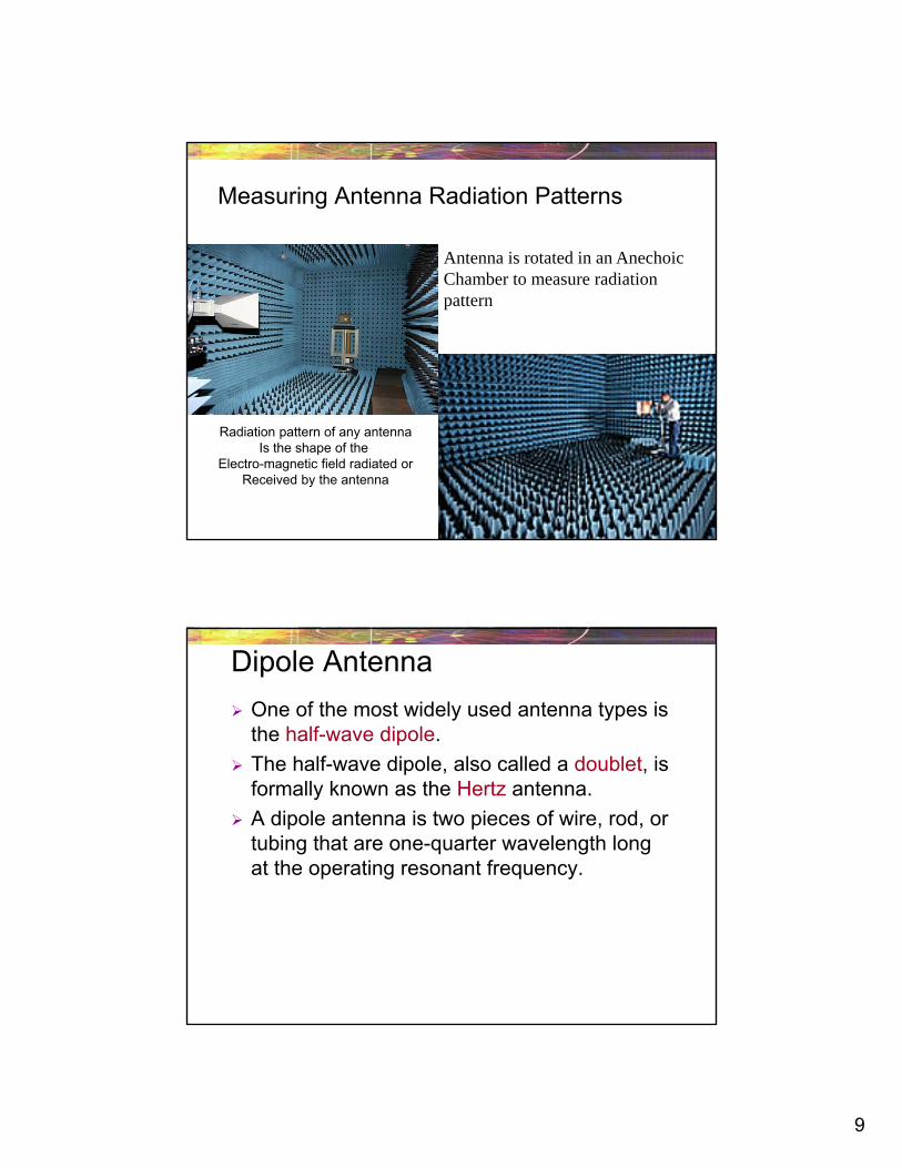
Measuring Antenna Radiation Patterns
Antenna is rotated in an AnechoicChamber to measure radiationpattern
Radiation pattern of any antennaIs the shape of the
Electro-magnetic field radiated orReceived by the antenna
Dipole Antenna
One of the most widely used antenna types is the half-wave dipole.
The half-wave dipole, also called a doublet, is formally known as the Hertz antenna.
A dipole antenna is two pieces of wire, rod, or tubing that are one-quarter wavelength long at the operating resonant frequency.
10
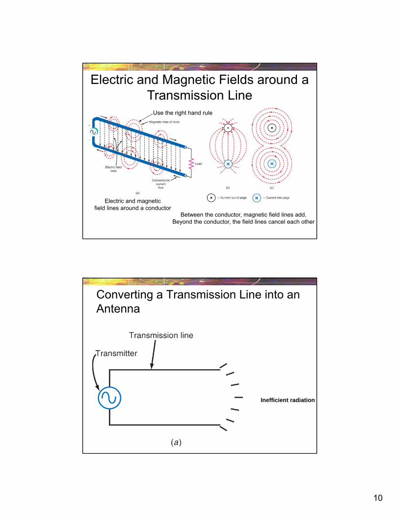
Electric and Magnetic Fields around a Transmission Line
Electric and magneticfield lines around a conductor
Between the conductor, magnetic field lines add.Beyond the conductor, the field lines cancel each other
Use the right hand rule
Converting a Transmission Line into an Antenna
Inefficient radiation
11
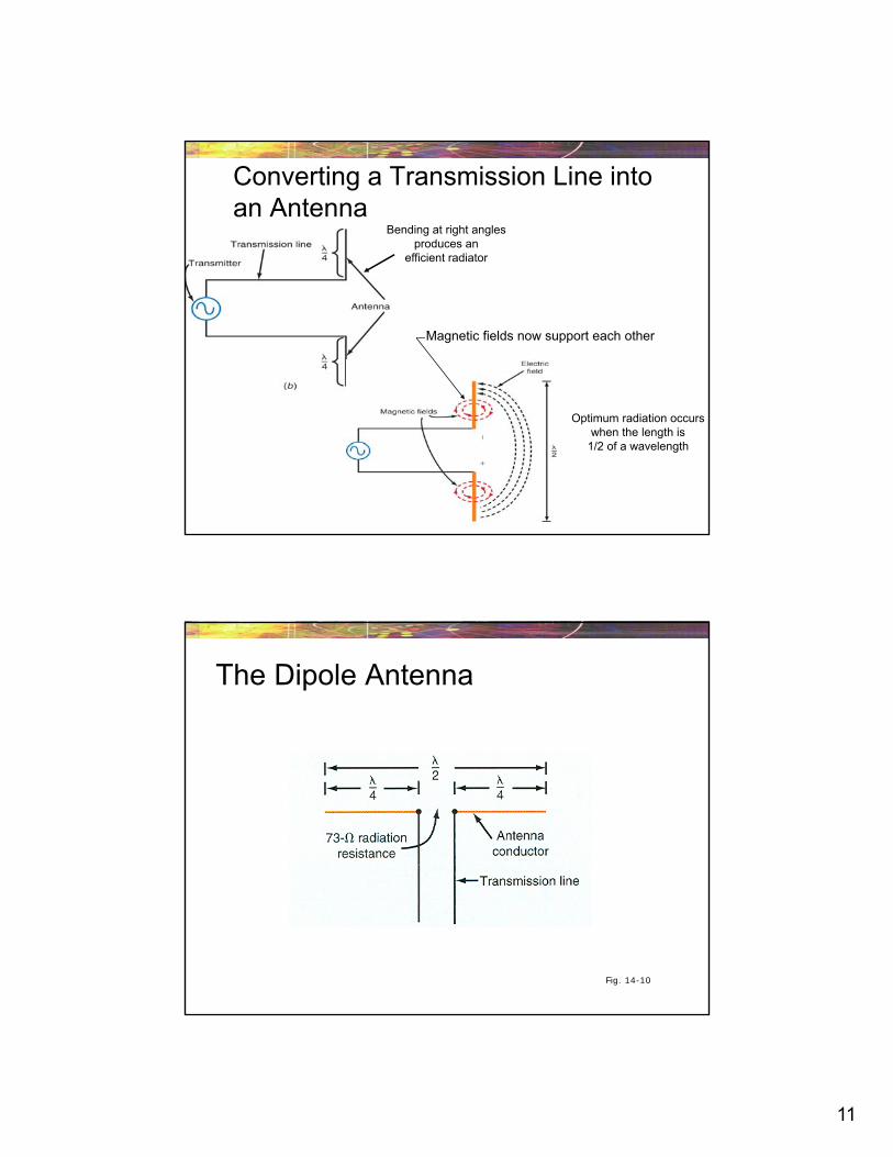
Converting a Transmission Line into an Antenna
Bending at right anglesproduces an
efficient radiator
Optimum radiation occurswhen the length is
1/2 of a wavelength
Magnetic fields now support each other
The Dipole Antenna
Fig. 14-10
12
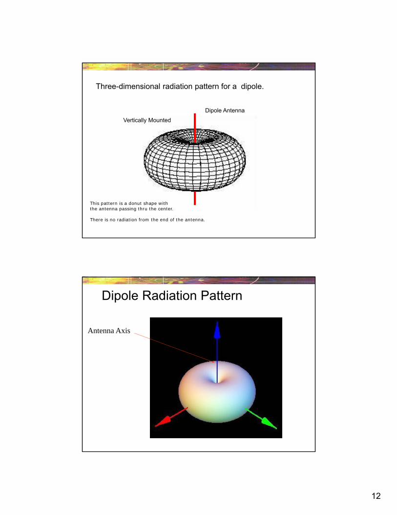
Three-dimensional radiation pattern for a dipole.
Dipole Antenna
Vertically Mounted
This pattern is a donut shape with the antenna passing thru the center.
There is no radiation from the end of the antenna.
Dipole Radiation Pattern
Antenna Axis
13
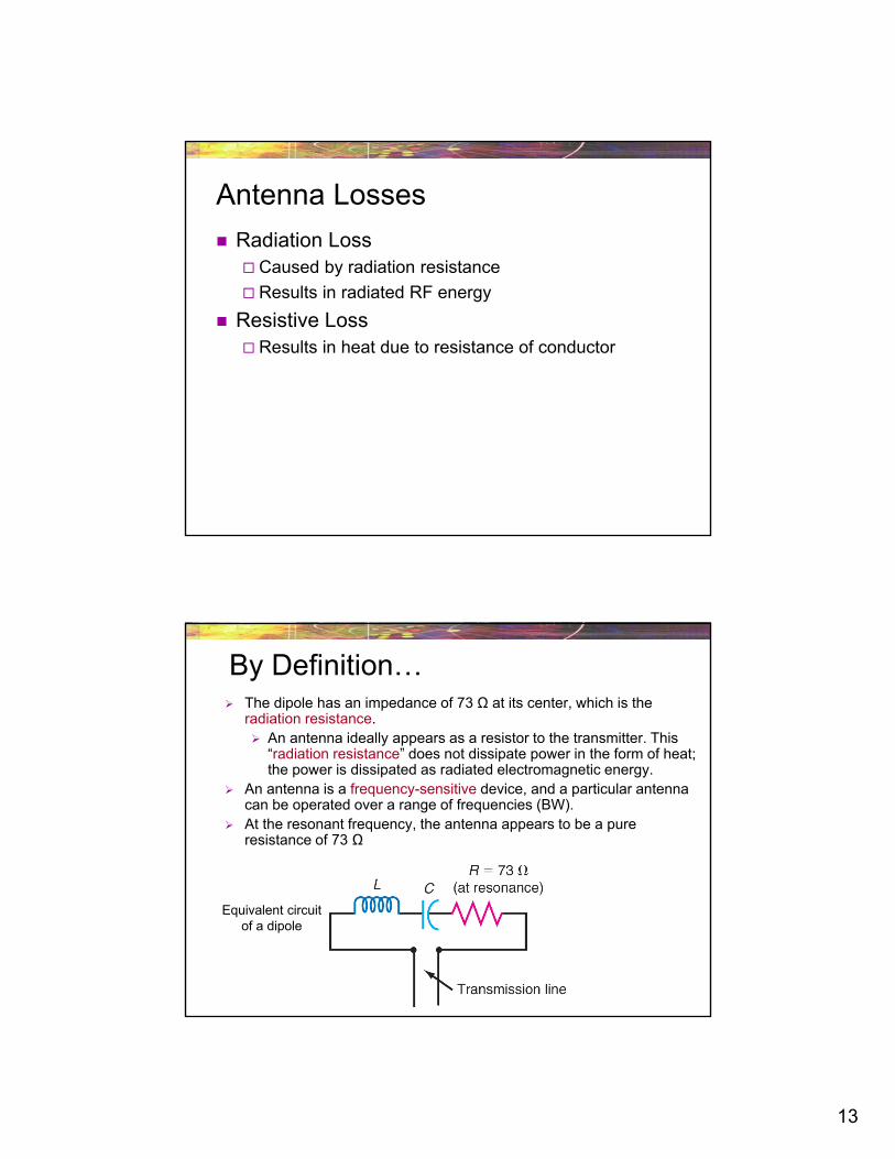
Antenna Losses
Radiation Loss Caused by radiation resistance
Results in radiated RF energy
Resistive Loss Results in heat due to resistance of conductor
By Definition… The dipole has an impedance of 73 Ω at its center, which is the
radiation resistance. An antenna ideally appears as a resistor to the transmitter. This
“radiation resistance” does not dissipate power in the form of heat; the power is dissipated as radiated electromagnetic energy.
An antenna is a frequency-sensitive device, and a particular antenna can be operated over a range of frequencies (BW).
At the resonant frequency, the antenna appears to be a pure resistance of 73 Ω
Equivalent circuitof a dipole
14
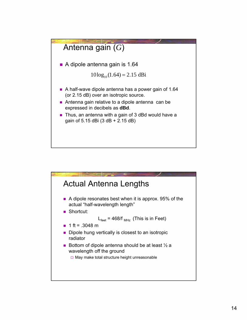
Antenna gain (G)
A dipole antenna gain is 1.64
A half-wave dipole antenna has a power gain of 1.64 (or 2.15 dB) over an isotropic source.
Antenna gain relative to a dipole antenna can be expressed in decibels as dBd.
Thus, an antenna with a gain of 3 dBd would have a gain of 5.15 dBi (3 dB + 2.15 dB)
1010log (1.64) 2.15 dBi
Actual Antenna Lengths
A dipole resonates best when it is approx. 95% of the actual “half-wavelength length”
Shortcut:
Lfeet = 468/f MHz (This is in Feet)
1 ft = .3048 m
Dipole hung vertically is closest to an isotropic radiator
Bottom of dipole antenna should be at least ½ a wavelength off the ground May make total structure height unreasonable
15
Example
How long would a dipole antenna be for AM 1100? Calculate using wavelength and shortcut
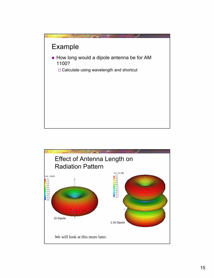
Effect of Antenna Length on Radiation Pattern
1.5λ Dipole
1λ Dipole
We will look at this more later.
16
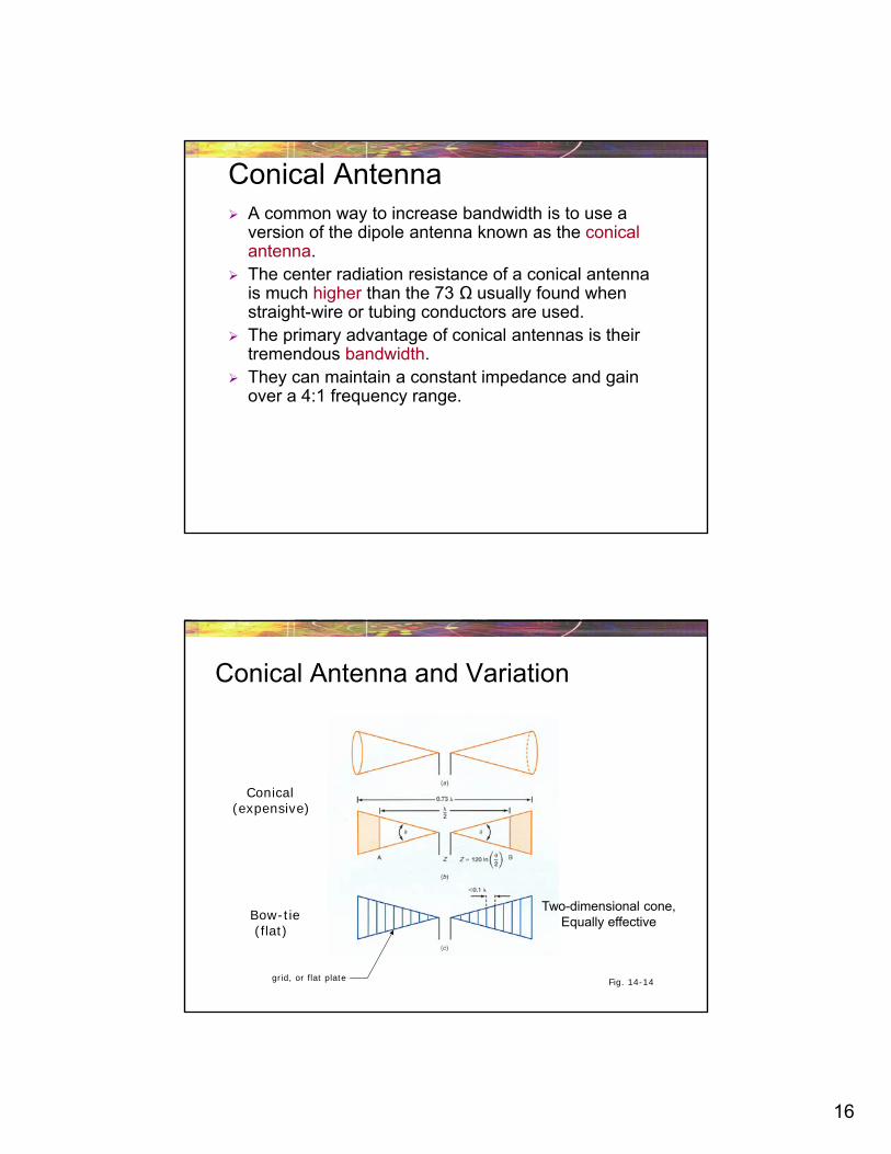
Conical Antenna A common way to increase bandwidth is to use a
version of the dipole antenna known as the conical antenna.
The center radiation resistance of a conical antenna is much higher than the 73 Ω usually found when straight-wire or tubing conductors are used.
The primary advantage of conical antennas is their tremendous bandwidth.
They can maintain a constant impedance and gain over a 4:1 frequency range.
Conical Antenna and Variation
Fig. 14-14
Conical(expensive)
Bow-tie(flat)
grid, or flat plate
Two-dimensional cone,Equally effective
17
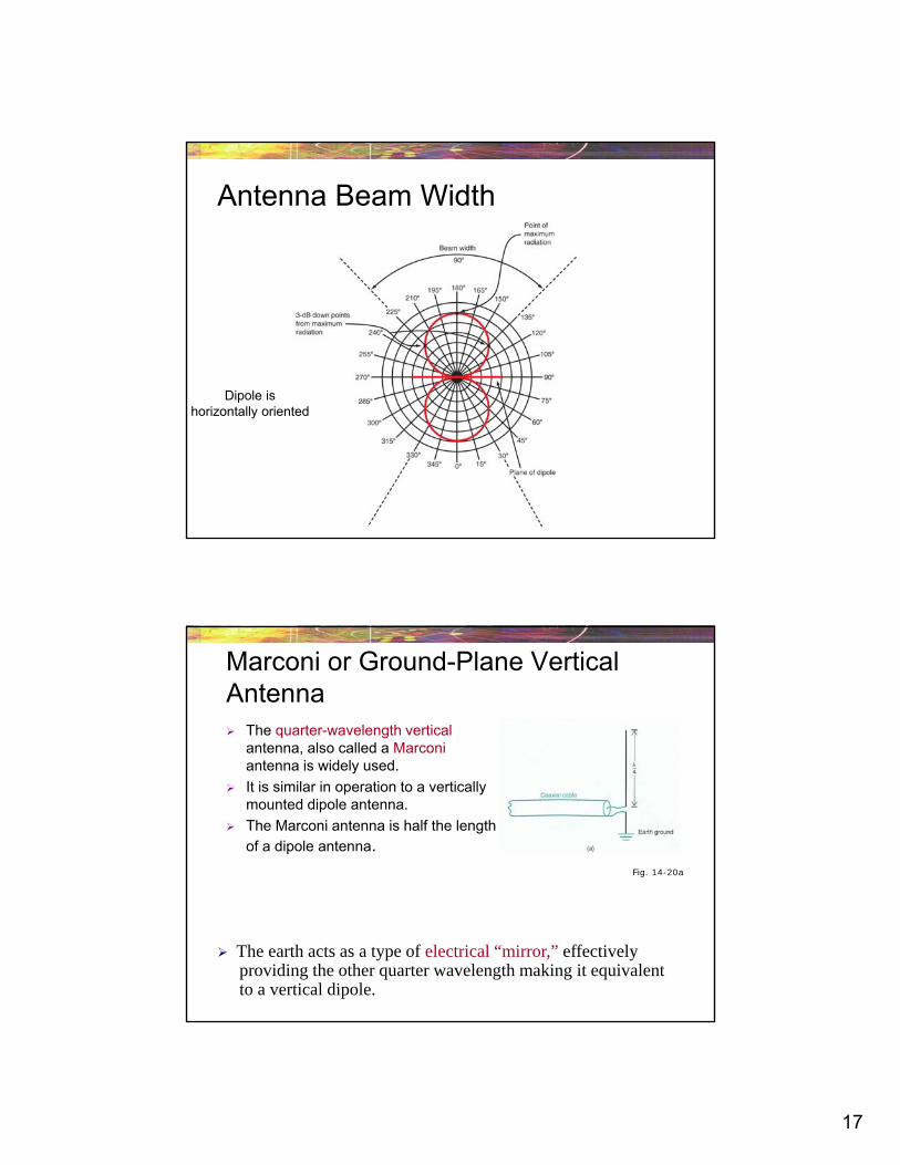
Antenna Beam Width
Dipole ishorizontally oriented
Marconi or Ground-Plane Vertical Antenna The quarter-wavelength vertical
antenna, also called a Marconi antenna is widely used.
It is similar in operation to a vertically mounted dipole antenna.
The Marconi antenna is half the length
of a dipole antenna.Fig. 14-20a
The earth acts as a type of electrical “mirror,” effectivelyproviding the other quarter wavelength making it equivalentto a vertical dipole.
18
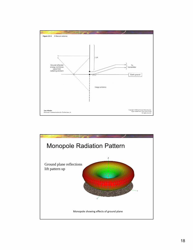
Figure 12–6 A Marconi antenna
Tom WheelerElectronic Communications for Technicians, 2e
Copyright ©2006 by Pearson Education, Inc.Upper Saddle River, New Jersey 07458
All rights reserved.
Monopole Radiation Pattern
Monopole showing effects of ground plane
Ground plane reflectionslift pattern up
19
Advantages
Half the length of a dipole
Can be located at earth level without degrading performance
Has omni-directional radiation pattern similar to dipole
Disadvantages
Gain is slightly lower than a dipole (about 1 dB less), but for our purposes we will consider them the same
Antenna is extremely dependent on conductivity of the earth
Using a counterpoise will improve conductivity
20
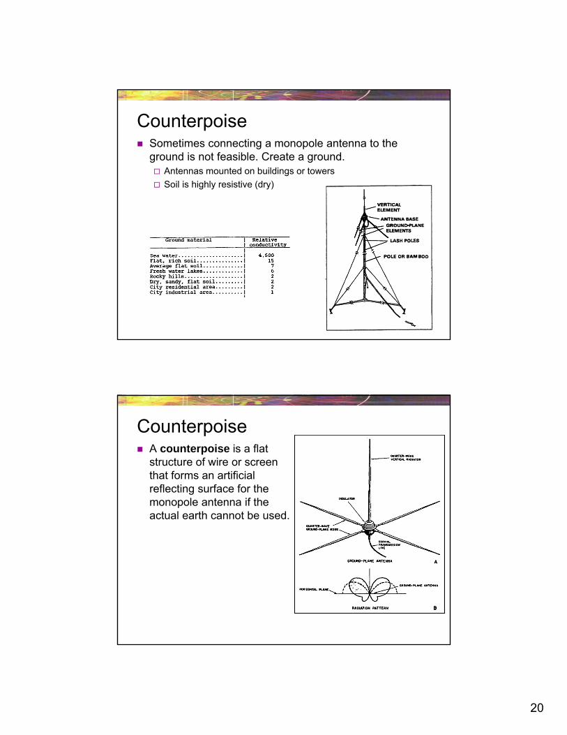
Sometimes connecting a monopole antenna to the ground is not feasible. Create a ground. Antennas mounted on buildings or towers
Soil is highly resistive (dry)
Counterpoise
A counterpoise is a flat structure of wire or screen that forms an artificial reflecting surface for the monopole antenna if the actual earth cannot be used.
Counterpoise
21
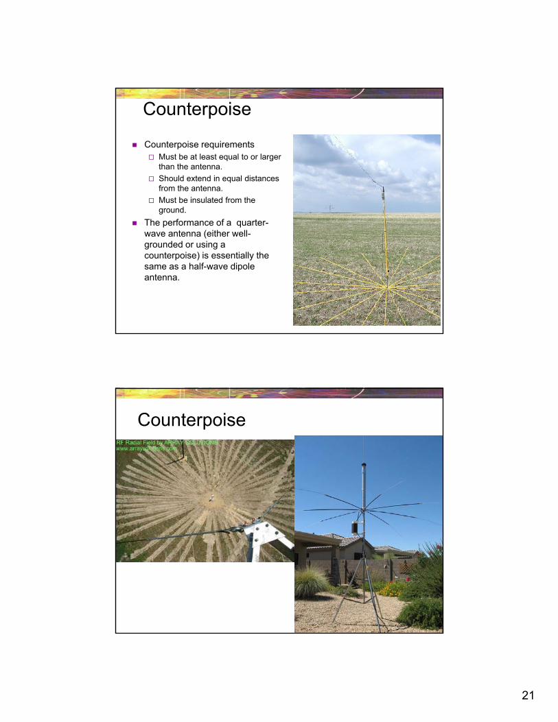
Counterpoise
Counterpoise requirements Must be at least equal to or larger
than the antenna.
Should extend in equal distances from the antenna.
Must be insulated from the ground.
The performance of a quarter-wave antenna (either well-grounded or using a counterpoise) is essentially the same as a half-wave dipole antenna.
Counterpoise
22
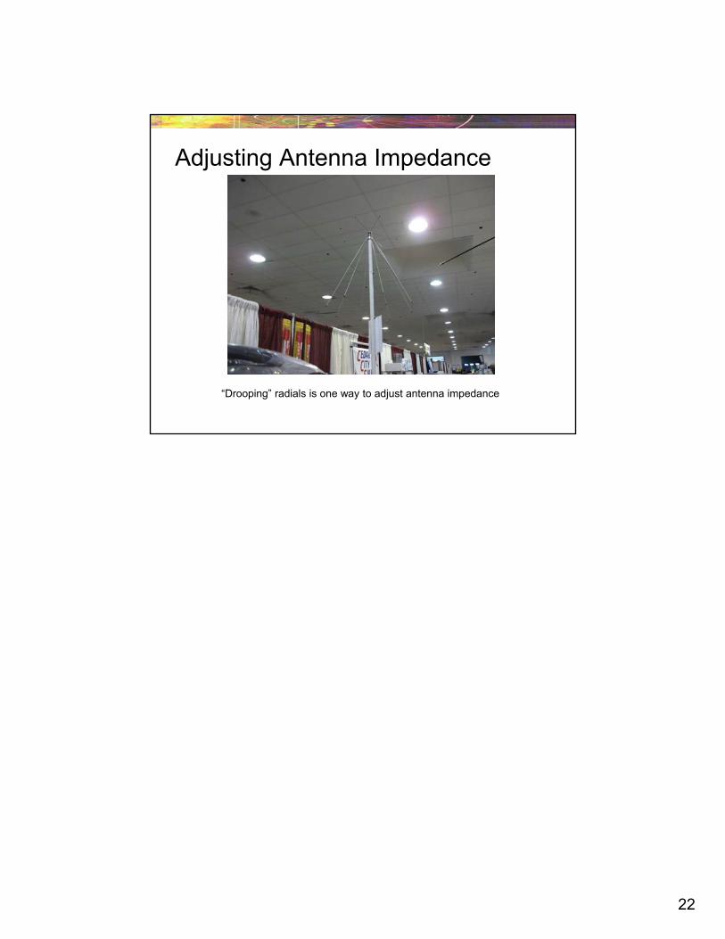
Adjusting Antenna Impedance
“Drooping” radials is one way to adjust antenna impedance
Recommended