REVISION
Contingency Plan

Motivation Word
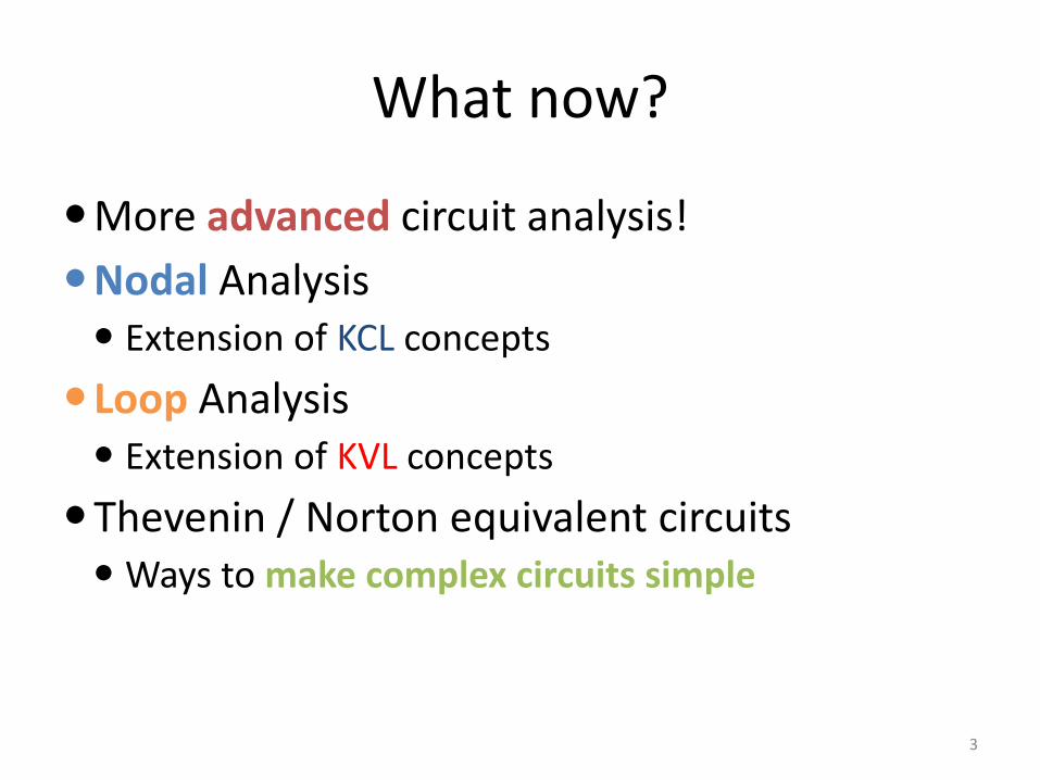
What now?
3
More advanced circuit analysis!
Nodal Analysis Extension of KCL concepts
Loop Analysis Extension of KVL concepts
Thevenin / Norton equivalent circuits Ways to make complex circuits simple
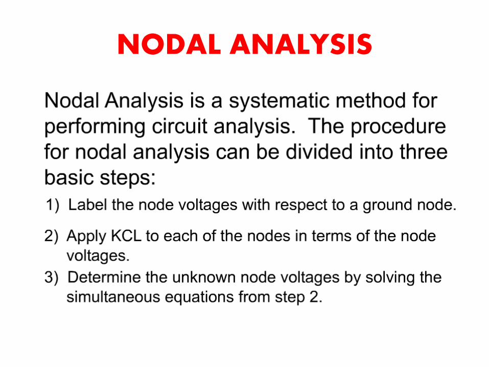
NODAL ANALYSIS
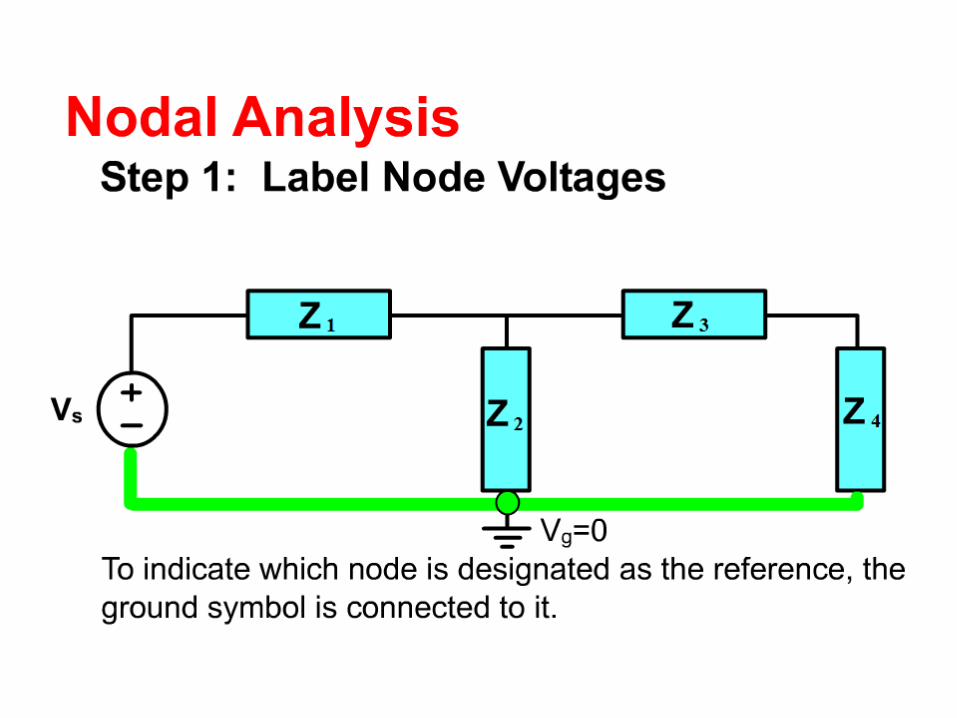
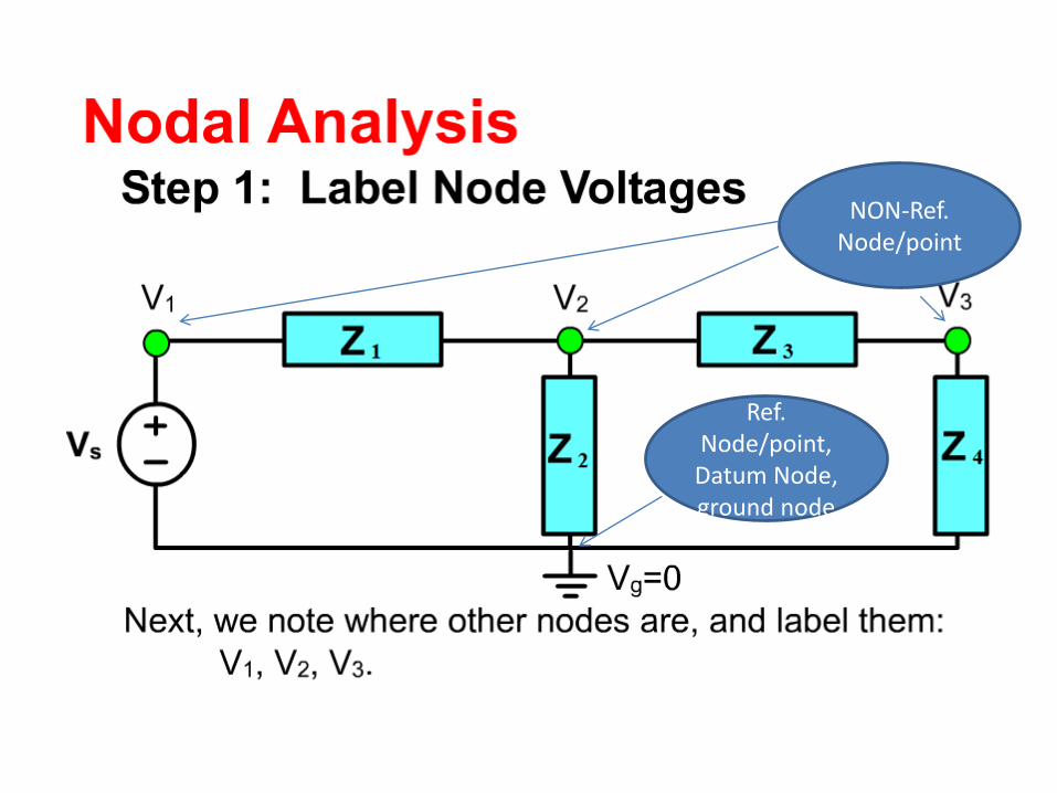
Ref. Node/point,
Datum Node, ground node
NON-Ref. Node/point
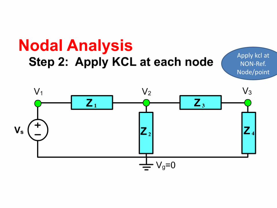
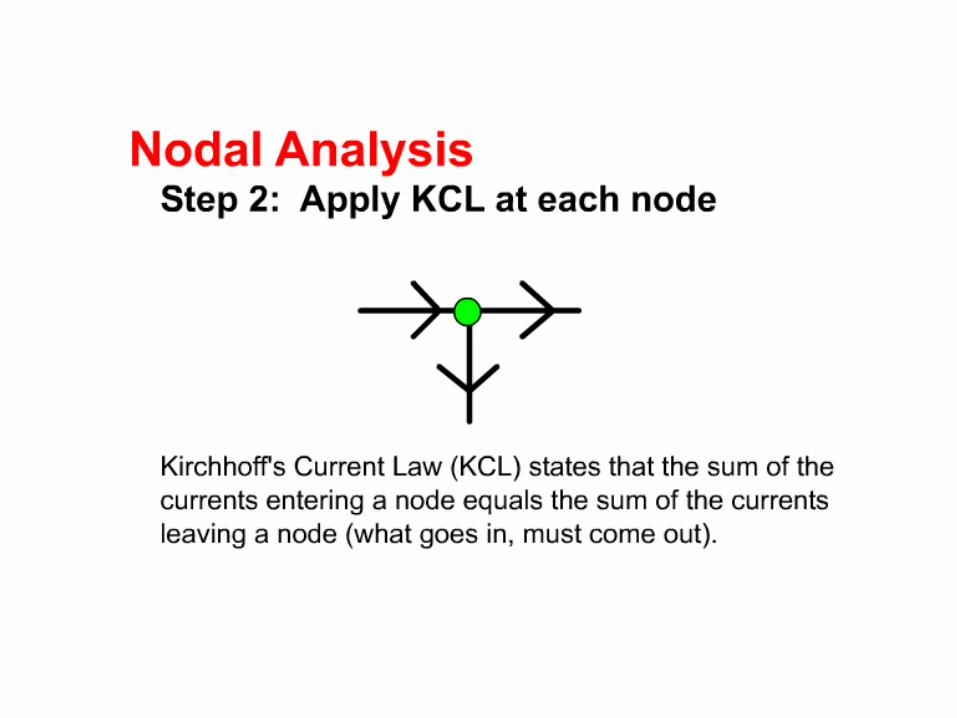
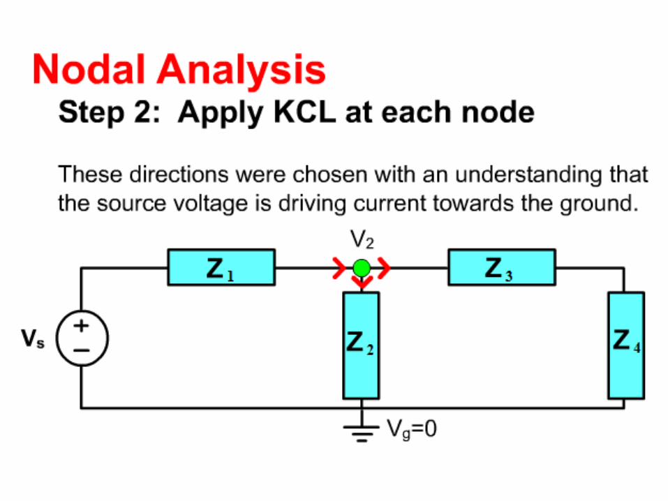
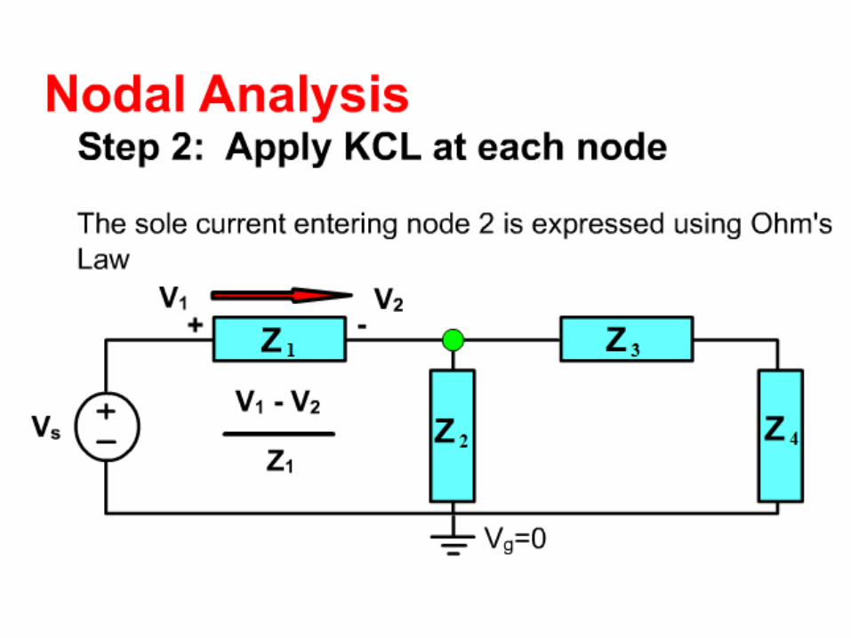
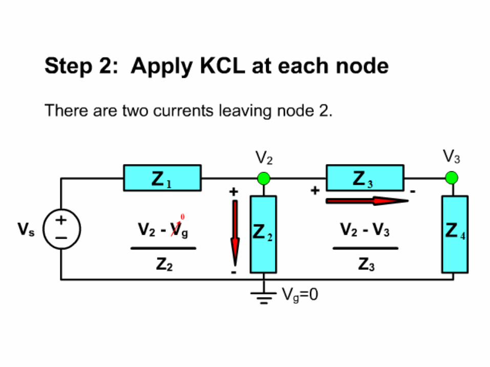
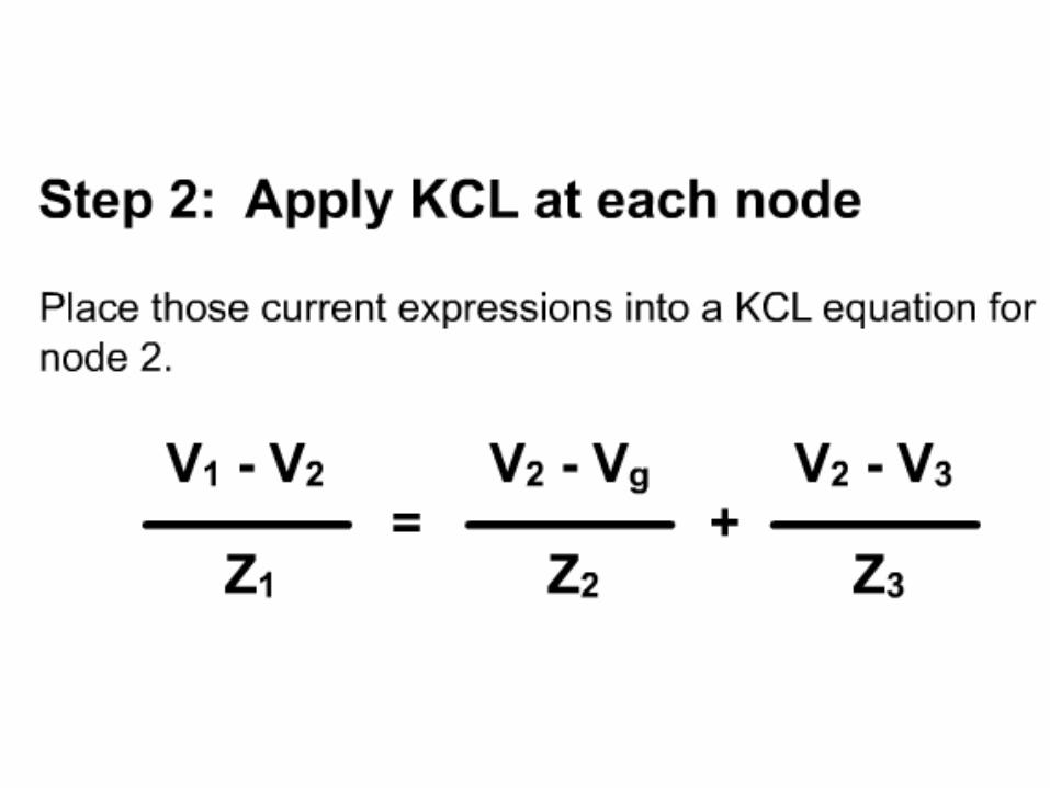
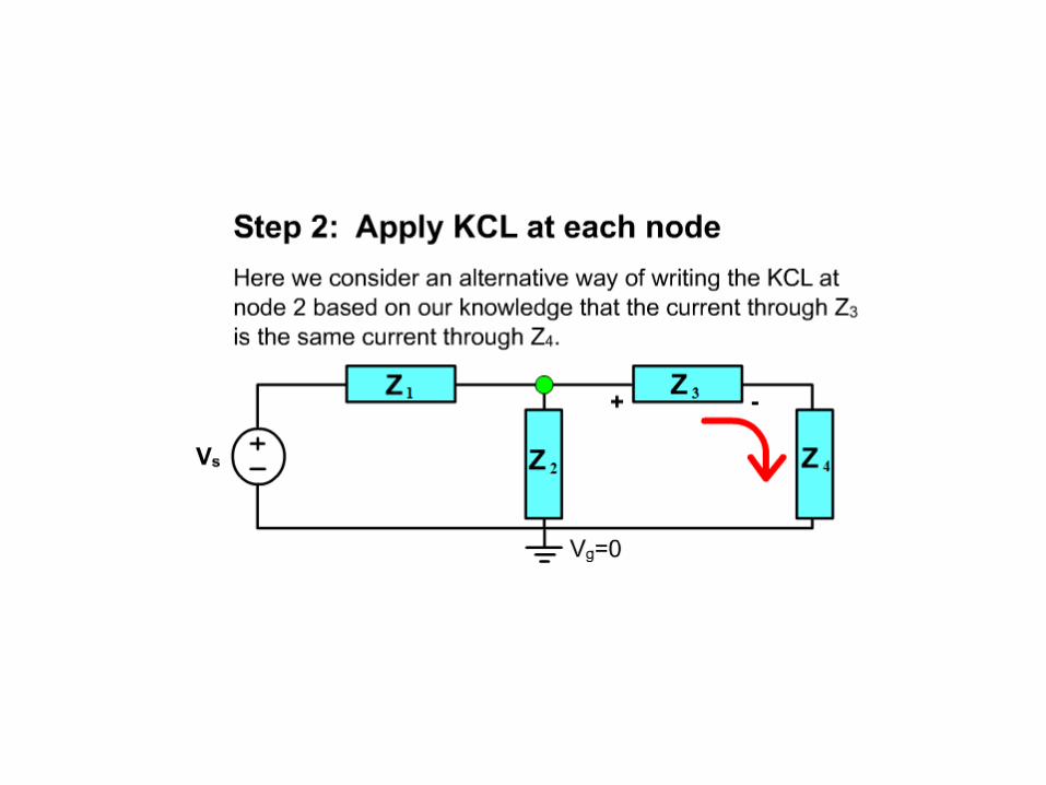
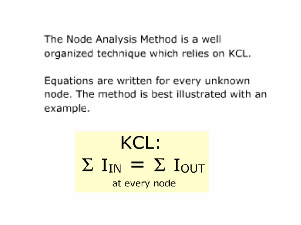
Apply kcl at NON-Ref.
Node/point
1
2
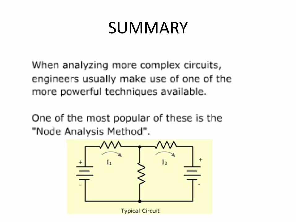
SUMMARY
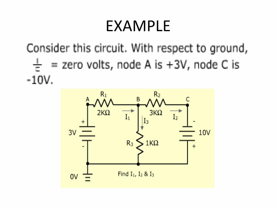
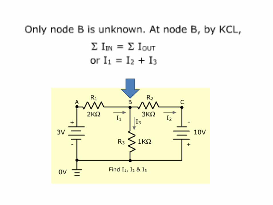
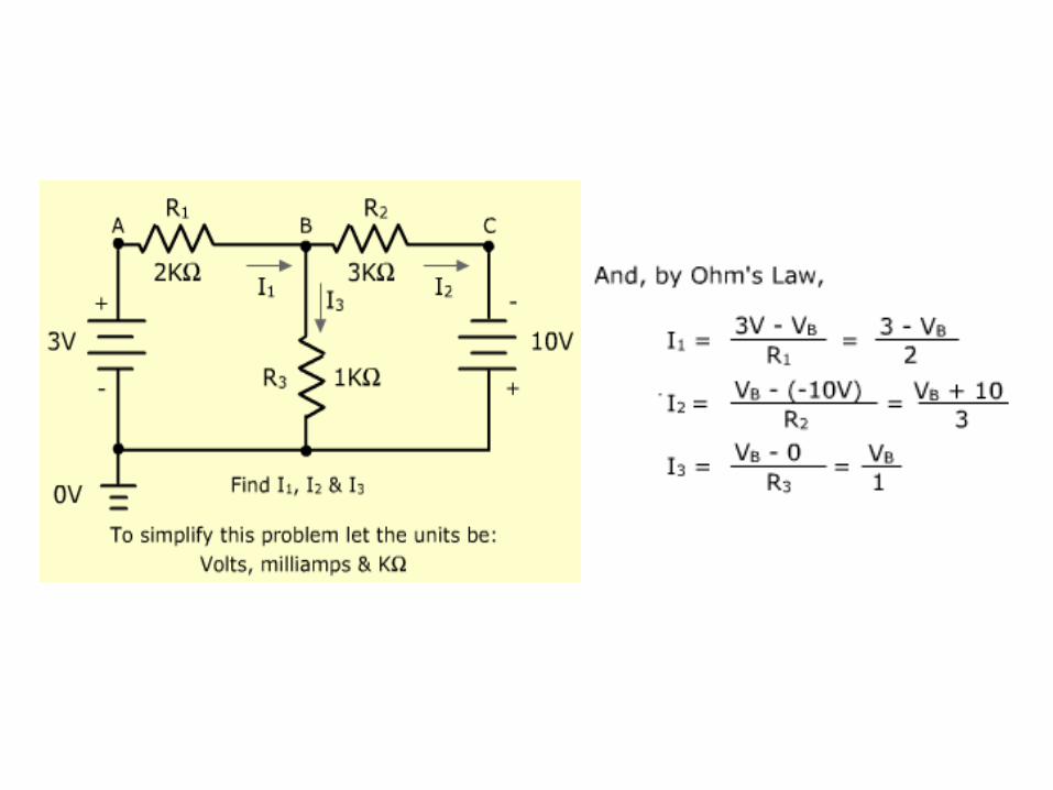
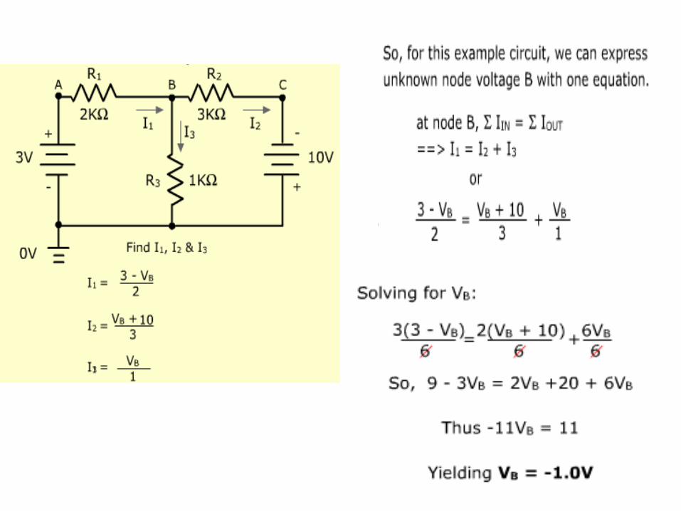
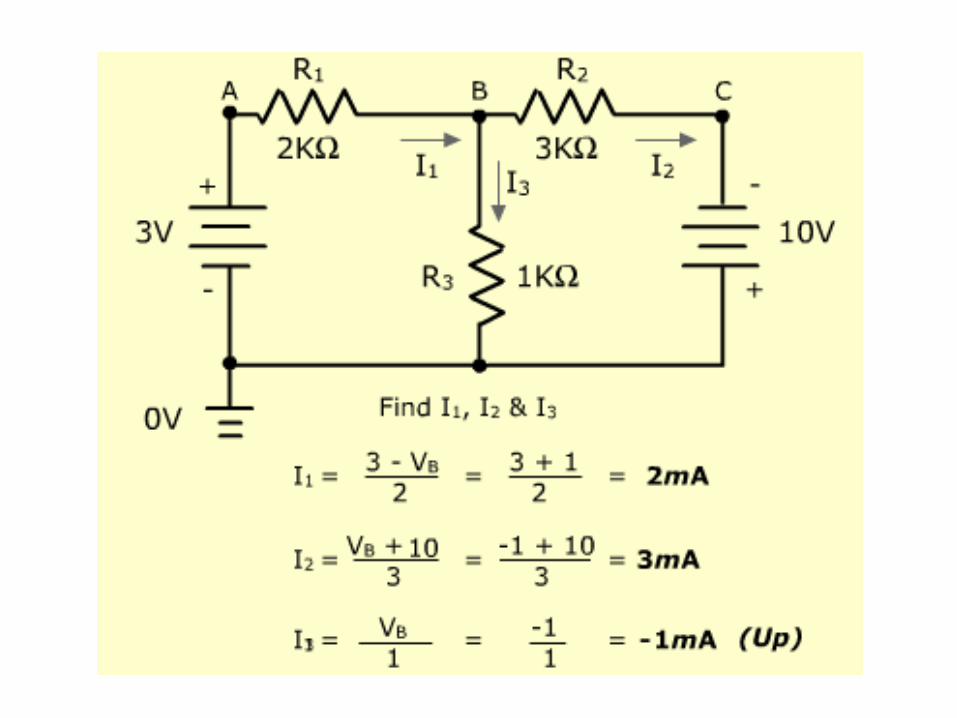
EXAMPLE
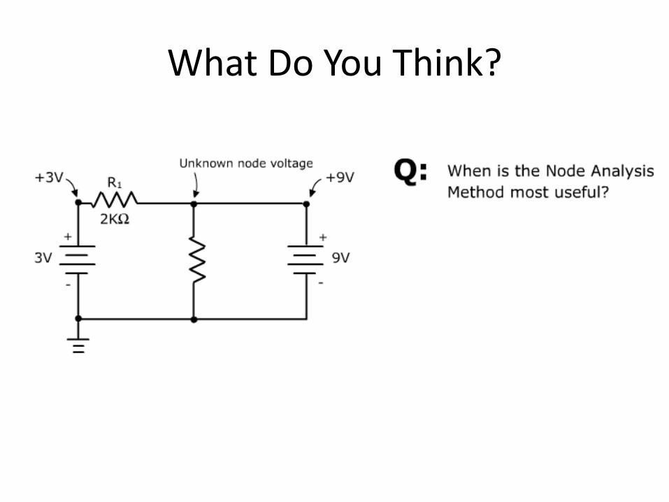
What Do You Think?
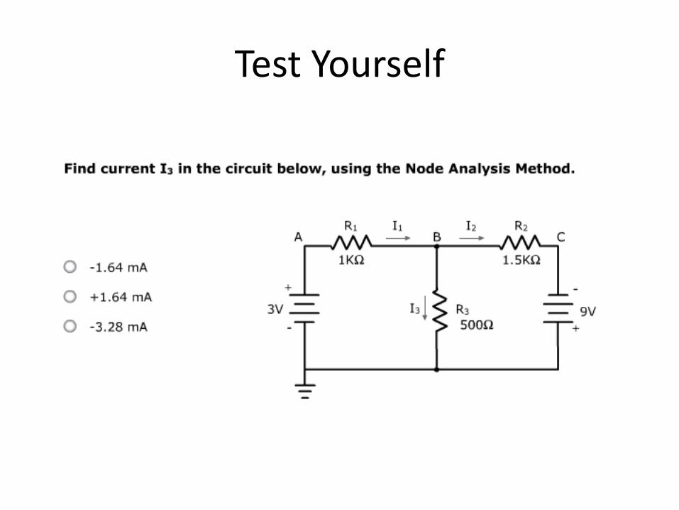
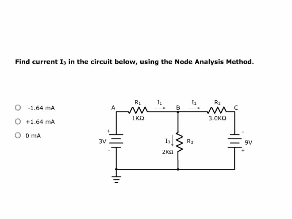
Test Yourself
`
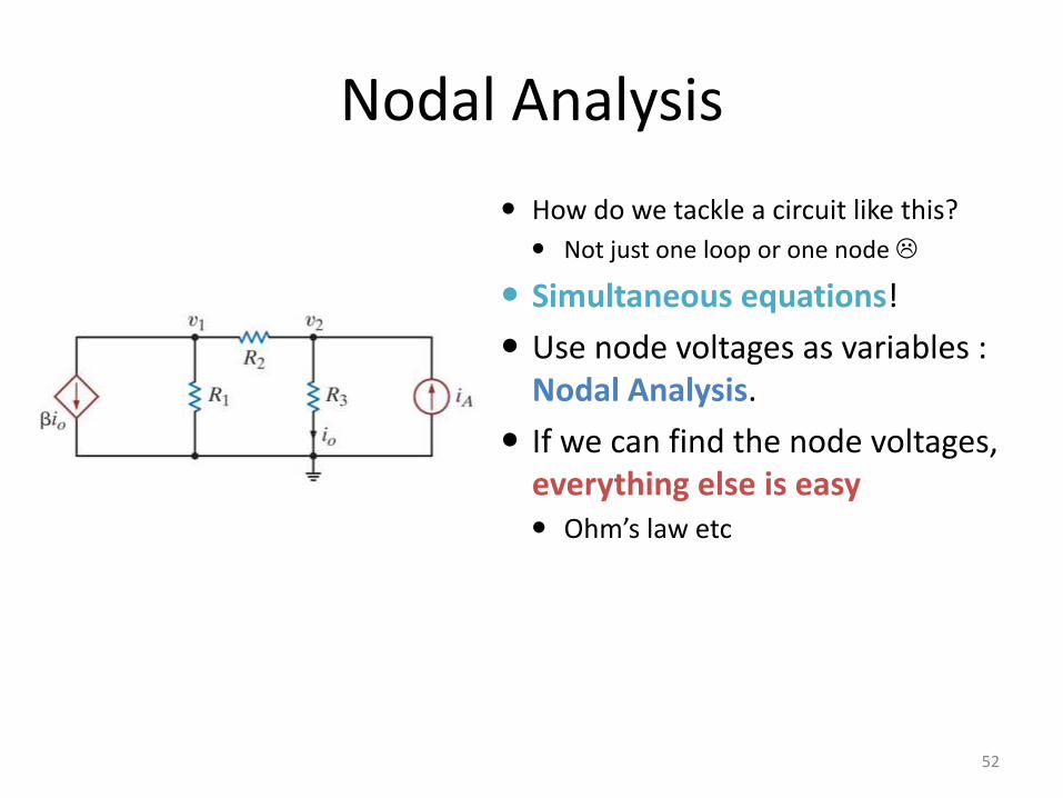
Nodal Analysis
52
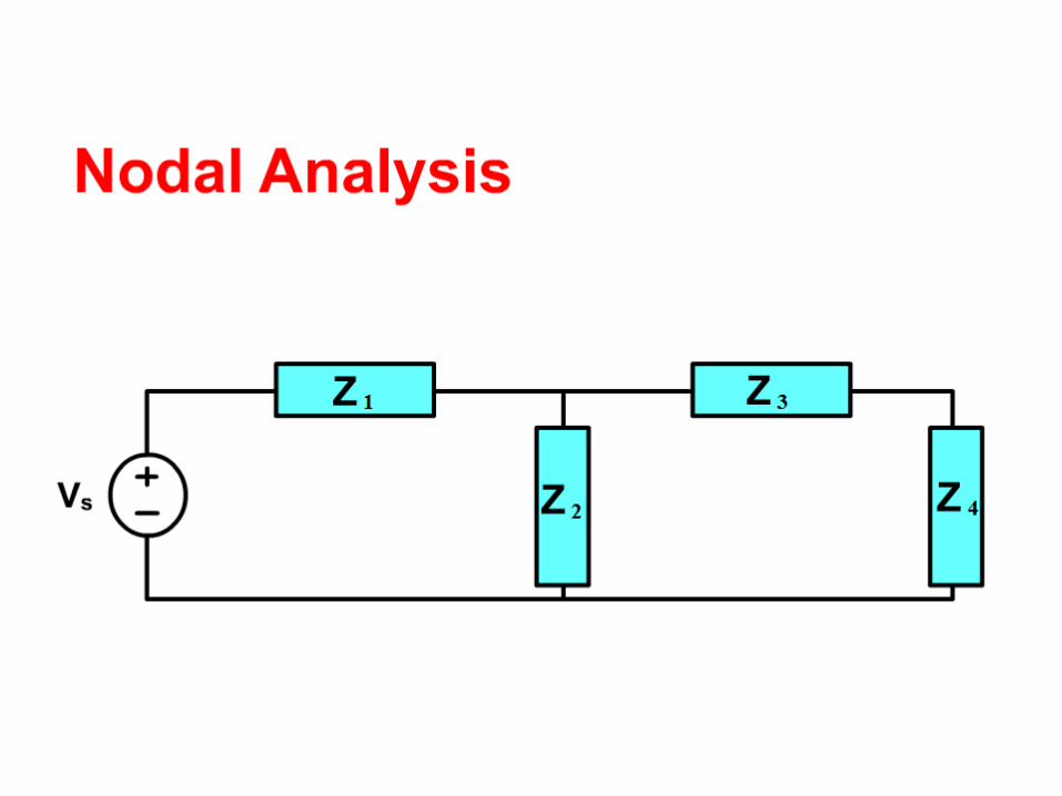
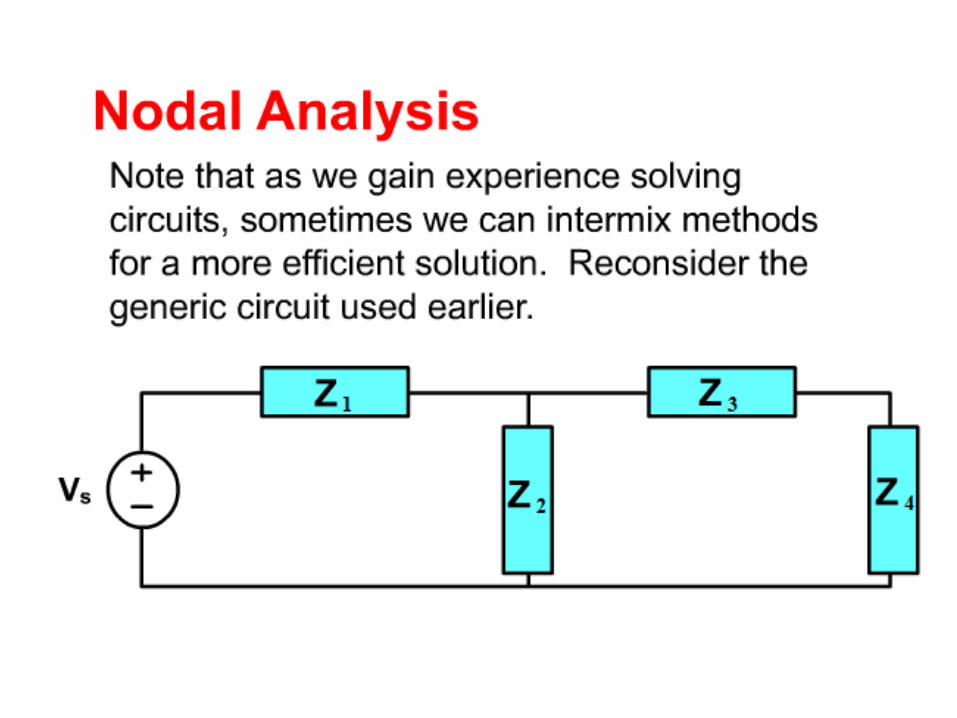
How do we tackle a circuit like this?
Not just one loop or one node
Simultaneous equations!
Use node voltages as variables : Nodal Analysis.
If we can find the node voltages, everything else is easy Ohm’s law etc
Nodal Analysis
53
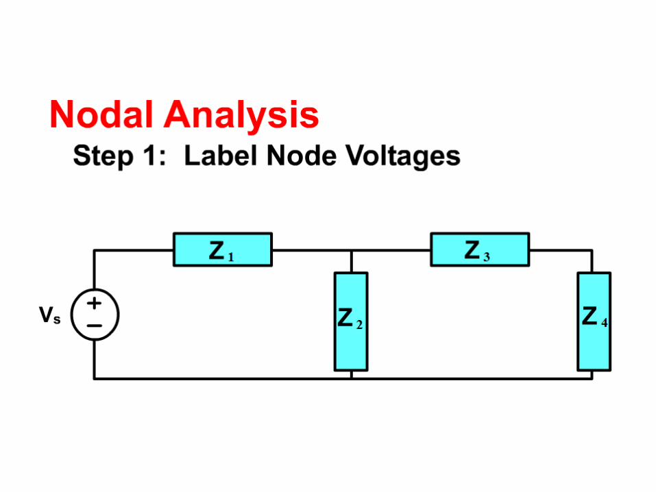
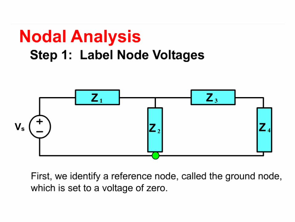
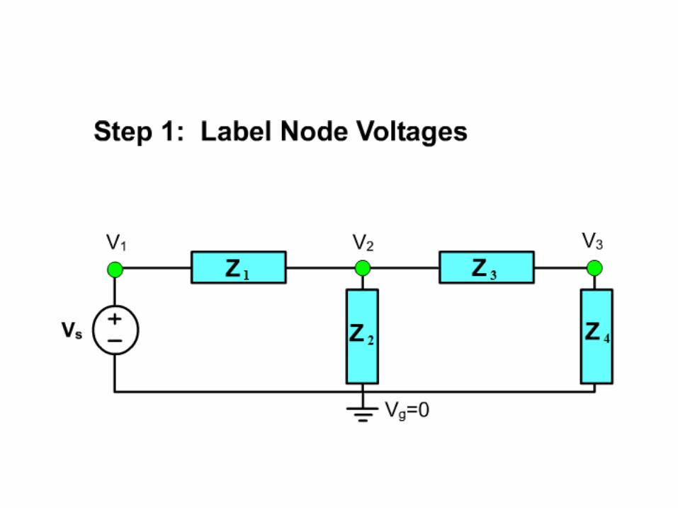
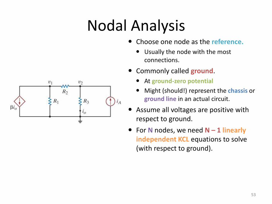
Choose one node as the reference.
Usually the node with the most connections.
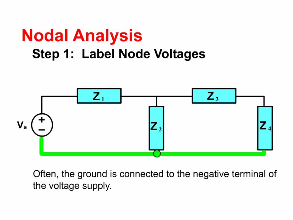
Commonly called ground.
At ground-zero potential
Might (should!) represent the chassis or ground line in an actual circuit.
Assume all voltages are positive with respect to ground.
For N nodes, we need N – 1 linearly independent KCL equations to solve (with respect to ground).
Nodal AnalysisCircuits with independent current sources
54
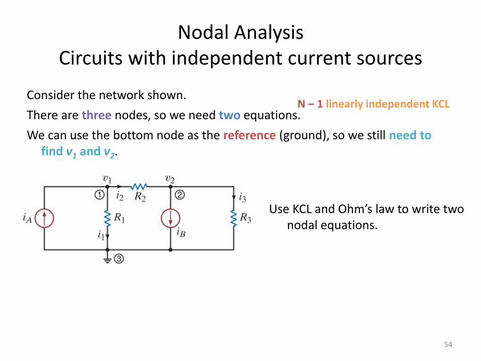
Consider the network shown.
There are three nodes, so we need two equations.
We can use the bottom node as the reference (ground), so we still need to find v1 and v2.
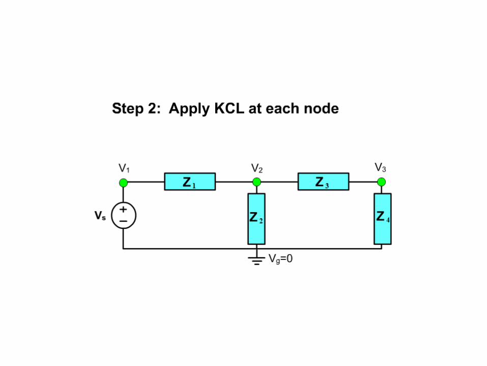
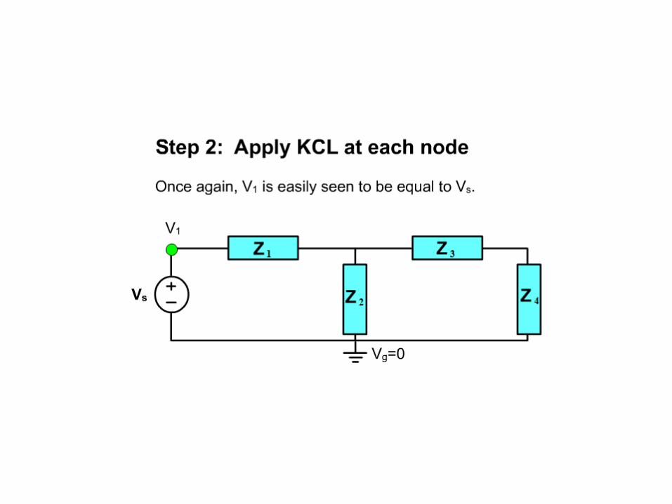
Use KCL and Ohm’s law to write two nodal equations.
N – 1 linearly independent KCL
Nodal AnalysisCircuits with independent current sources
55
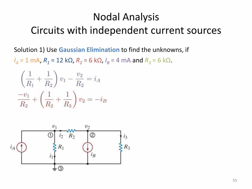
Solution 1) Use Gaussian Elimination to find the unknowns, if
IA = 1 mA, R1 = 12 kΩ, R2 = 6 kΩ, IB = 4 mA and R3 = 6 kΩ.
Nodal AnalysisCircuits with independent current sources
56
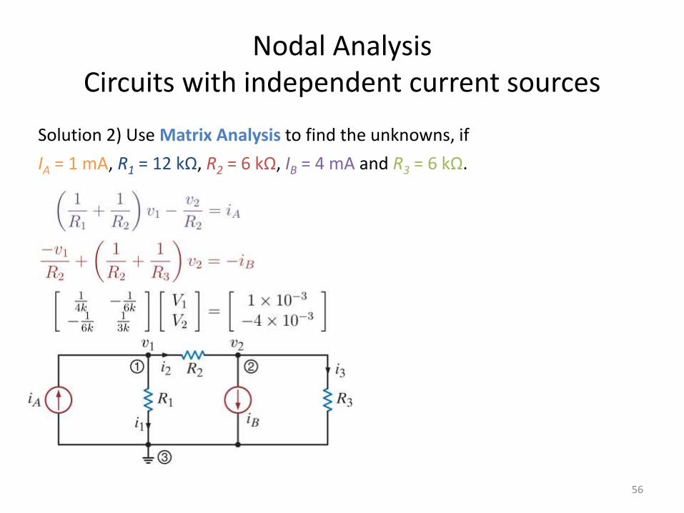
Solution 2) Use Matrix Analysis to find the unknowns, if
IA = 1 mA, R1 = 12 kΩ, R2 = 6 kΩ, IB = 4 mA and R3 = 6 kΩ.
Example
57
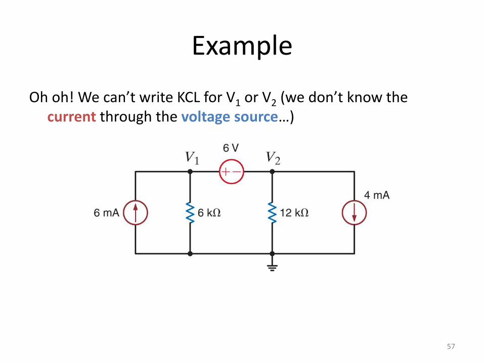
Oh oh! We can’t write KCL for V1 or V2 (we don’t know the current through the voltage source…)
Example
58
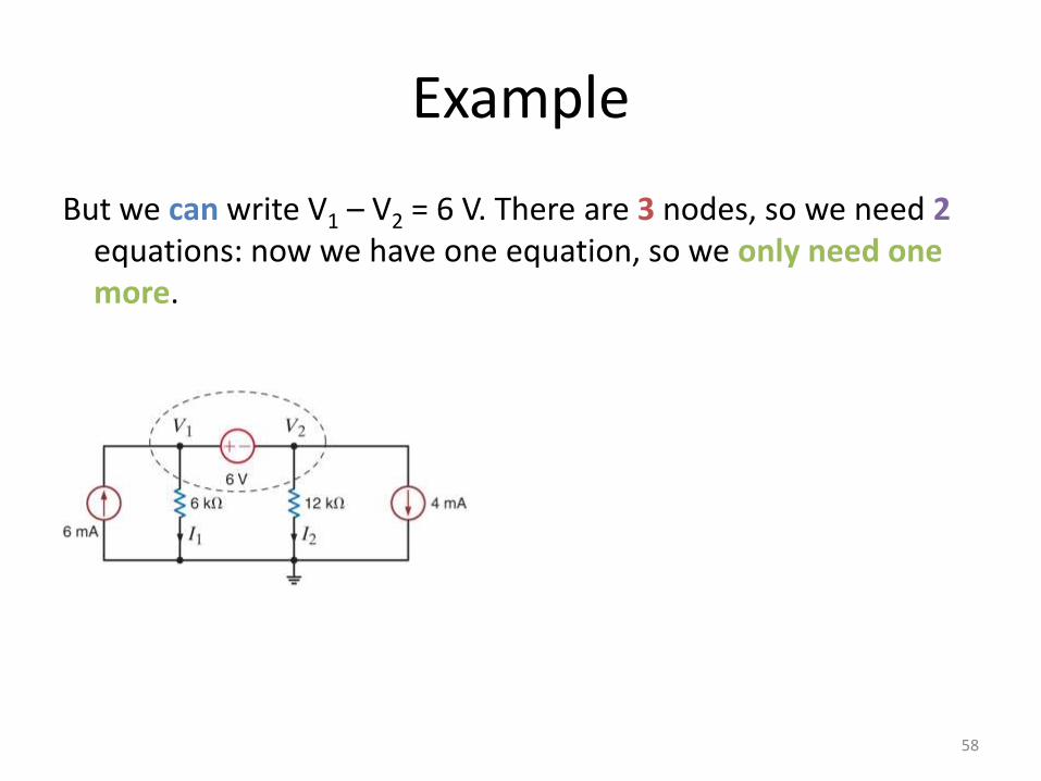
But we can write V1 – V2 = 6 V. There are 3 nodes, so we need 2equations: now we have one equation, so we only need one more.
Summary:Problem Solving Strategy
59
Step 1)
Determine the number of nodes, select one as the reference (ground). Assign voltage names to the other nodes.
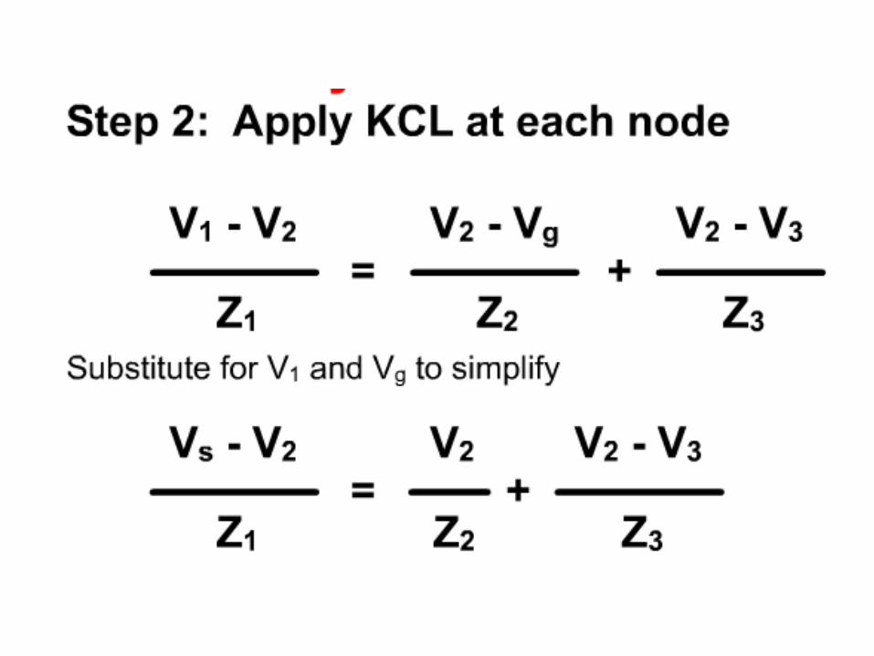
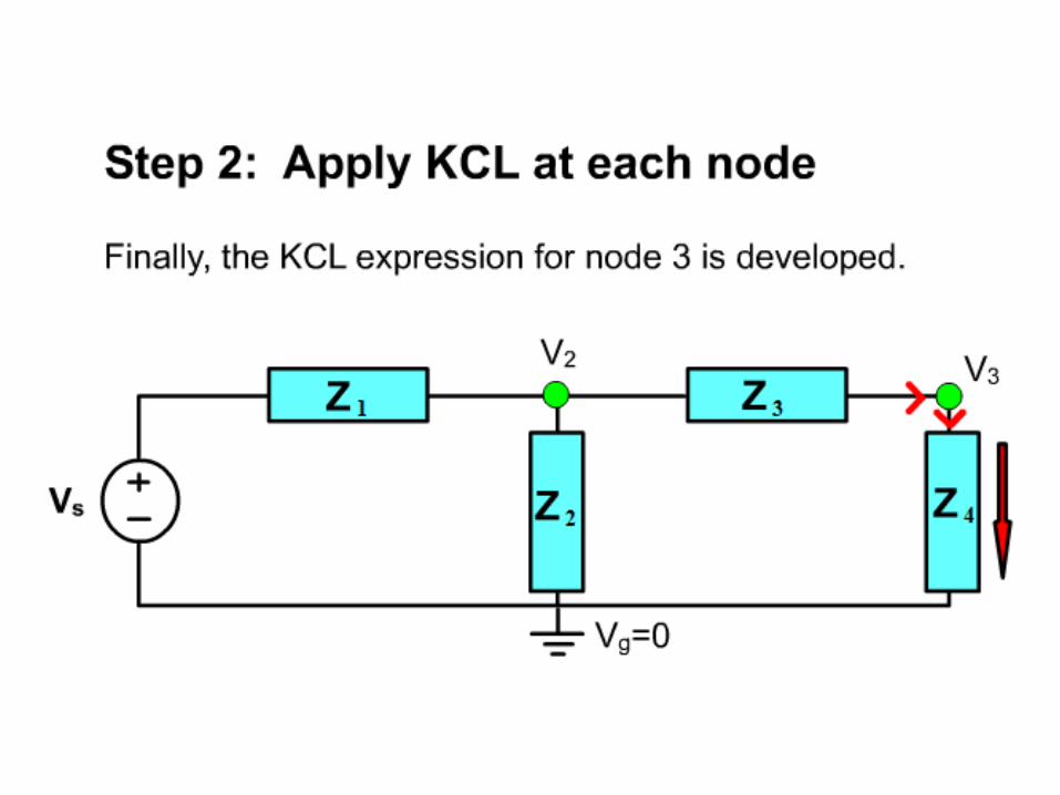
Step 2)
Write an equation for each voltage source (i.e.: V2 = 12 V, or V1 – V4 = -6 V). Each of these equations is one of the linearly independent equations we will use. Identify supernodes when a voltage source connects between two non-reference nodes.
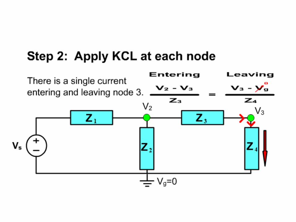
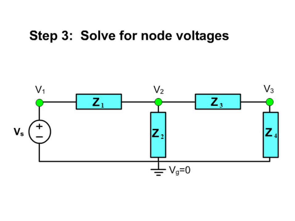
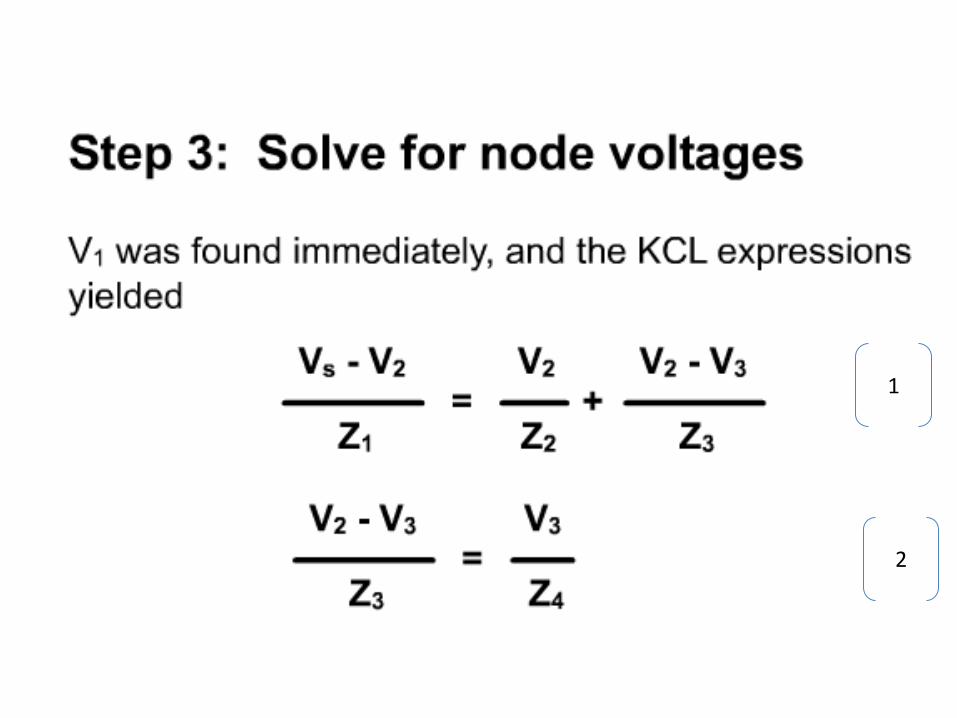
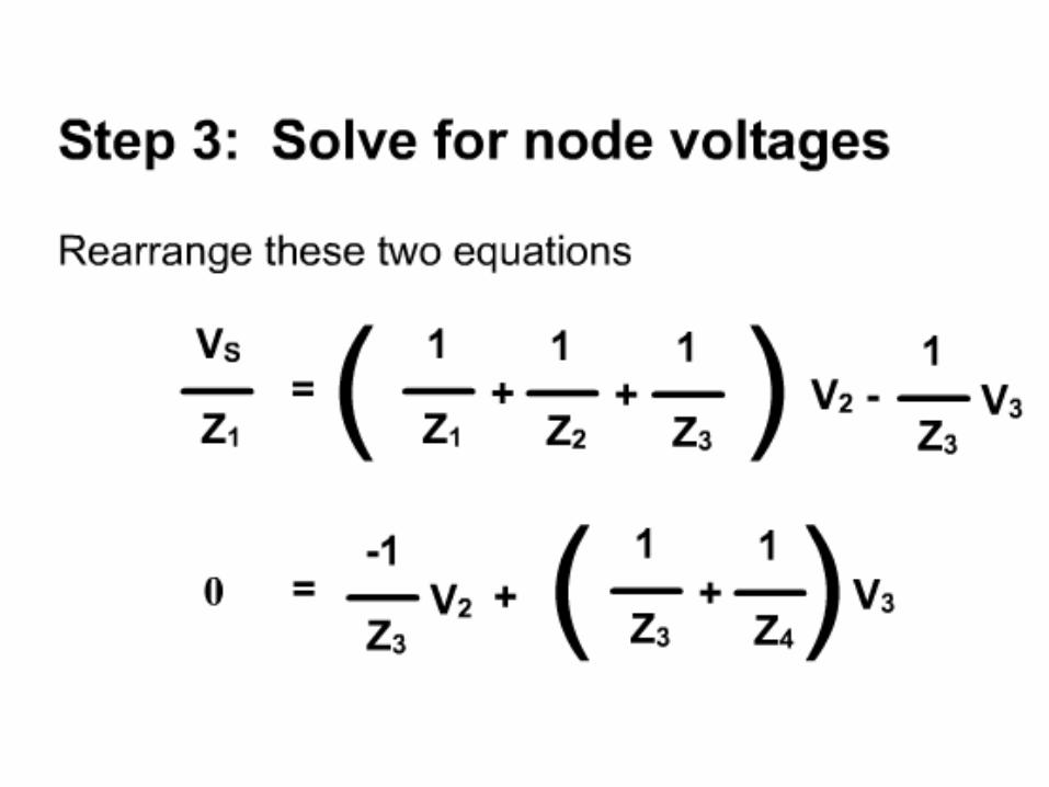
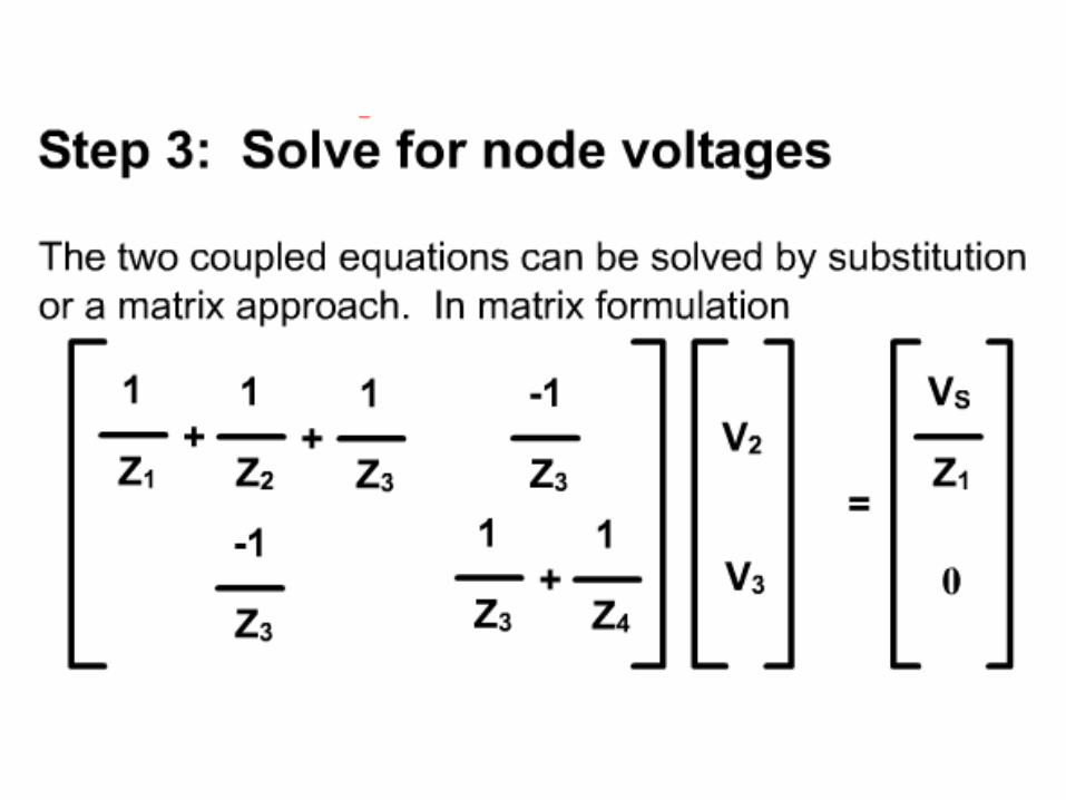
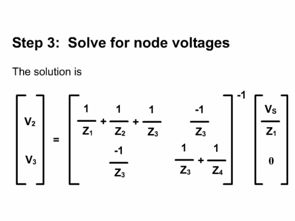
Step 3)
Use KCL to write the remaining equations. For N nodes, you will need a total of N – 1 equations. Solve to find the unknown voltages.

Chap 1 – Steady State Analysis
Sinusoidal Steady State Analysis
• Any steady state voltage or current in a linear circuit with a sinusoidal source is a sinusoid
– All steady state voltages and currents have the same frequency as the source
• In order to find a steady state voltage or current, all we need toknow is its magnitude and its phase relative to the source (wealready know its frequency)
• We do not have to find this differential equation from the circuit, nordo we have to solve it
• Instead, we use the concepts of phasors and complex impedances
• Phasors and complex impedances convert problems involvingdifferential equations into circuit analysis problems
Focus on steady state; Focus on sinusoids.
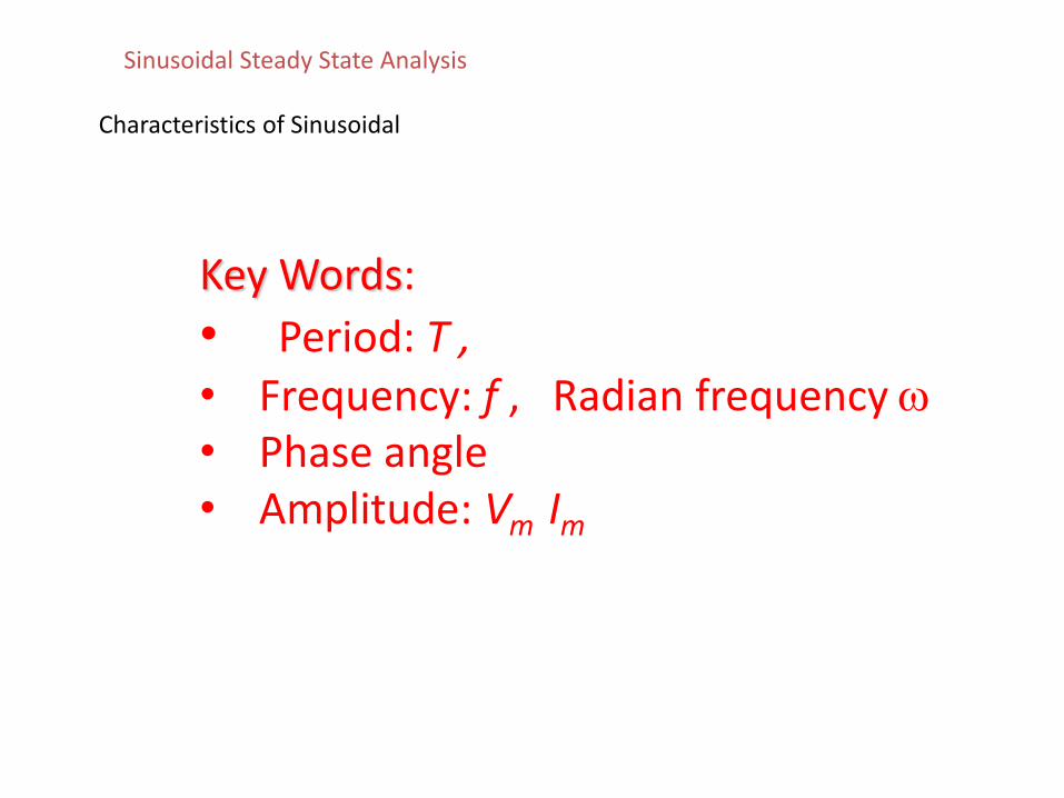
Characteristics of Sinusoidal
Key Words:
• Period: T , • Frequency: f , Radian frequency • Phase angle• Amplitude: Vm Im
Sinusoidal Steady State Analysis
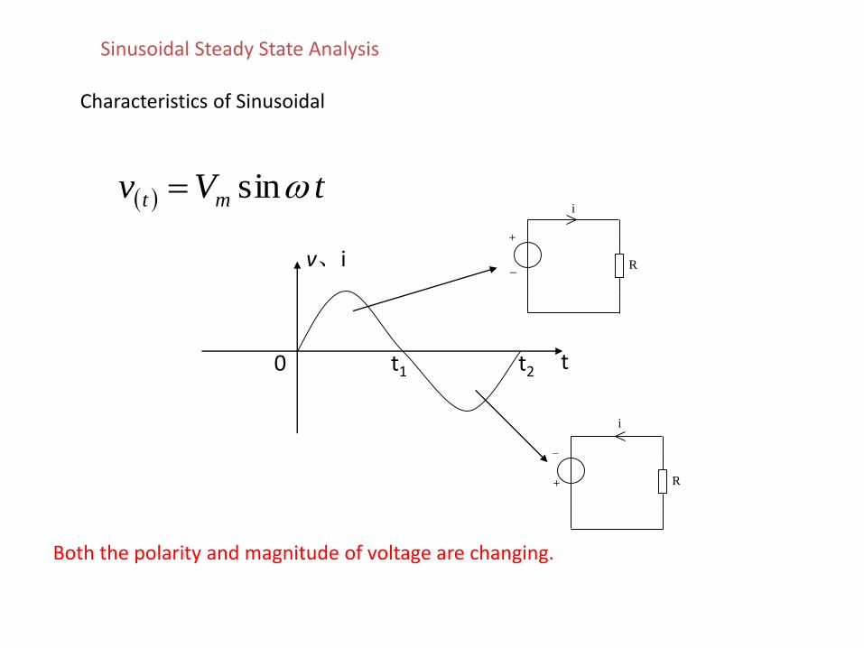
Characteristics of Sinusoidal
tVv mt sin i
I1
I1
I1 I1 I1 I1
R1
R1
R
5
5
+
_
IS
E
I1
U1
+
- U
I
i
I1 I1 I1 I1
R1
R1
R
5
5
-
+
IS
E
I1
U1
+
- U
I
v、i
tt1 t20
Both the polarity and magnitude of voltage are changing.
Sinusoidal Steady State Analysis
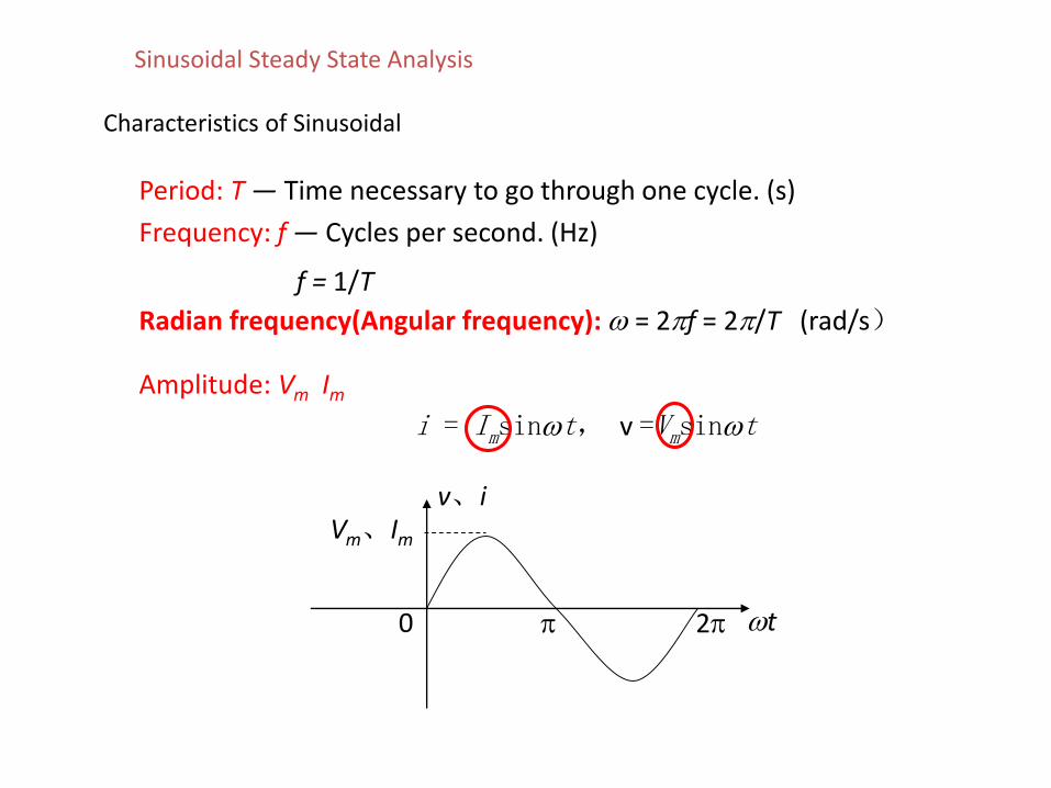
Characteristics of Sinusoidal
Radian frequency(Angular frequency): = 2f = 2/T (rad/s)
Period: T — Time necessary to go through one cycle. (s)
Frequency: f — Cycles per second. (Hz)
f = 1/T
Amplitude: Vm Im
i = Imsint, v =Vmsint
v、i
t 20
Vm、Im
Sinusoidal Steady State Analysis
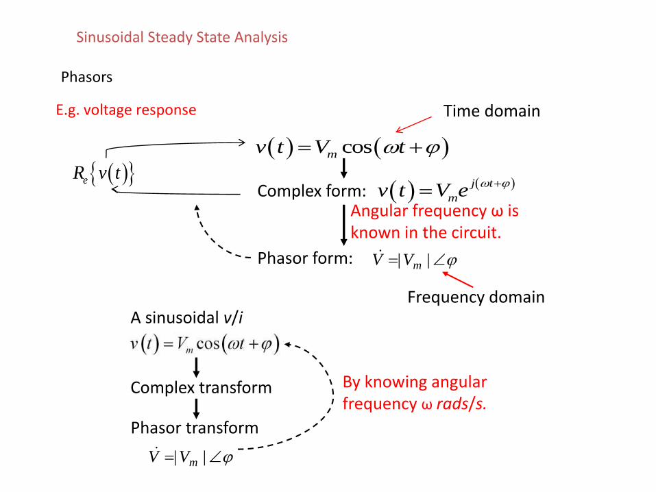
Phasors
E.g. voltage response
A sinusoidal v/i
Complex transform
Phasor transform
By knowing angular frequency ω rads/s.
Time domain
Frequency domain
eR v tComplex form:
cosmv t V t
Phasor form:
j t
mv t V e
Angular frequency ω is known in the circuit.
Sinusoidal Steady State Analysis
|| mVV
|| mVV
Phasors
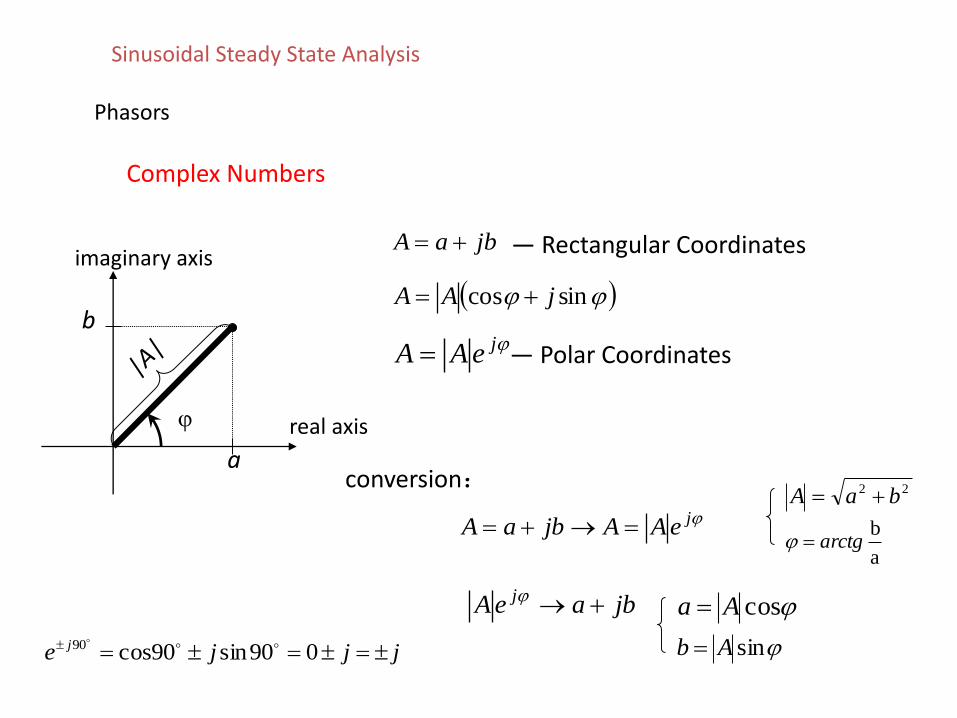
Complex Numbers
jbaA — Rectangular Coordinates
sincos jAA
jeAA — Polar Coordinates
jeAAjbaA
conversion: 22 baA
a
barctg
jbaeA j cosAa
sinAb
a
b
real axis
imaginary axis
jjje j 090sin90cos90
Sinusoidal Steady State Analysis
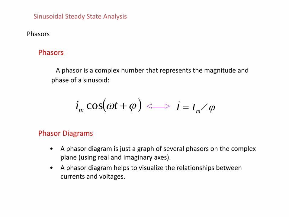
Phasors
Phasors
A phasor is a complex number that represents the magnitude and
phase of a sinusoid:
tim cos mII
Phasor Diagrams
• A phasor diagram is just a graph of several phasors on the complex plane (using real and imaginary axes).
• A phasor diagram helps to visualize the relationships between currents and voltages.
Sinusoidal Steady State Analysis
68
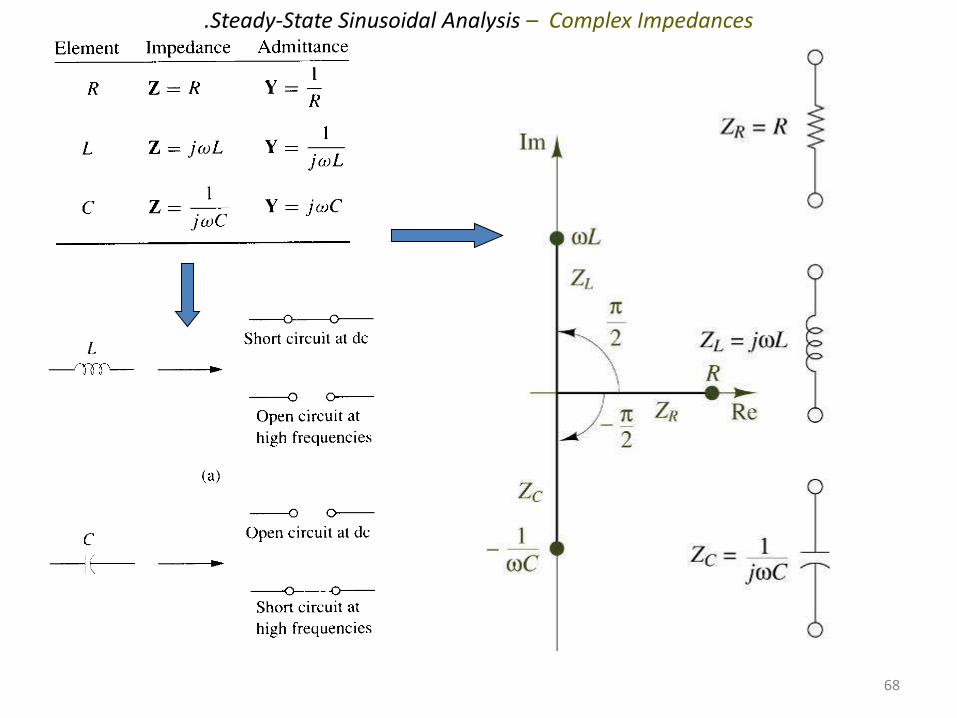
.Steady-State Sinusoidal Analysis – Complex Impedances
Phasor Relationships for R, L and C
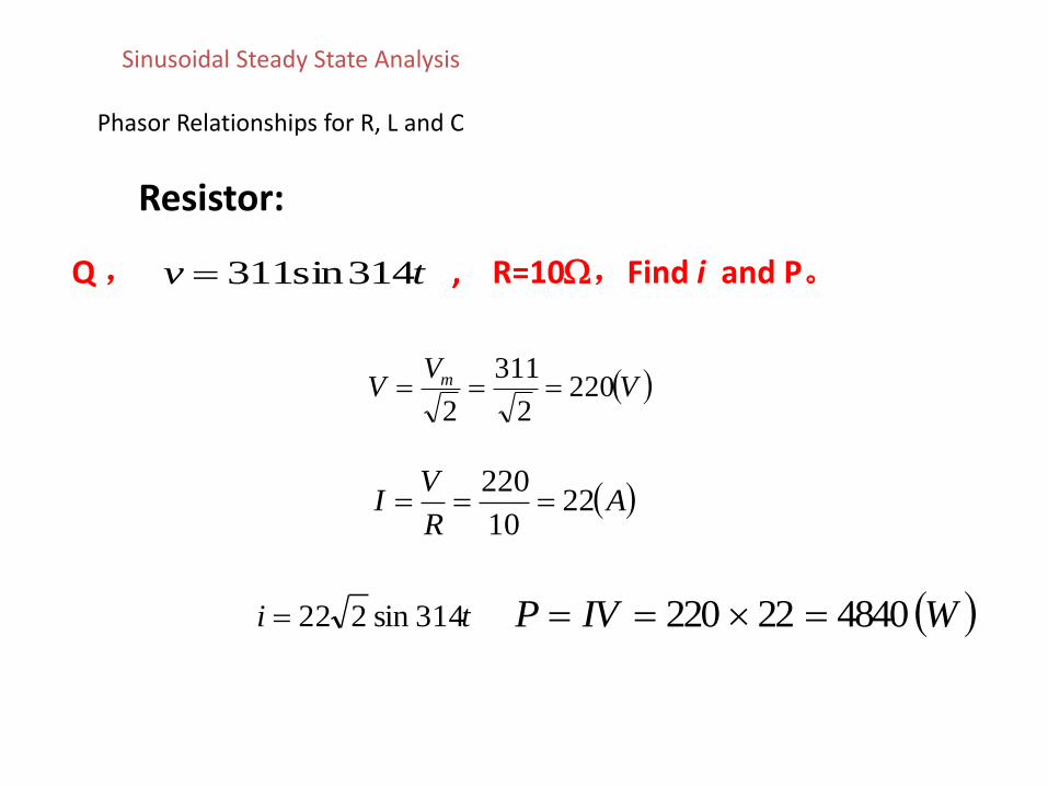
Resistor:
Q , , R=10,Find i and P。tv 314sin311
VV
V m 2202
311
2
AR
VI 22
10
220
ti 314sin222 WIVP 484022220
Sinusoidal Steady State Analysis
Phasor Relationships for R, L and C
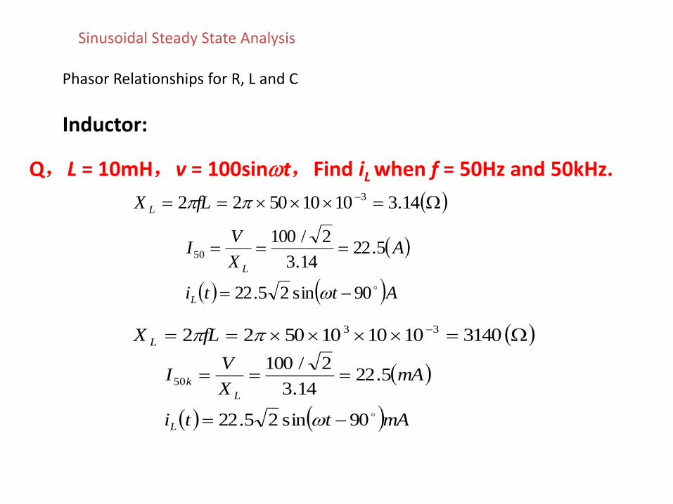
Inductor:
Q,L = 10mH,v = 100sint,Find iL when f = 50Hz and 50kHz.
14.310105022 3fLX L
Atti
AX
VI
L
L
90sin25.22
5.2214.3
2/10050
31401010105022 33fLX L
mAtti
mAX
VI
L
L
k
90sin25.22
5.2214.3
2/10050
Sinusoidal Steady State Analysis
Phasor Relationships for R, L and C
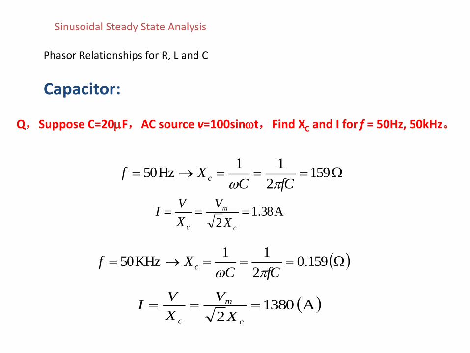
Capacitor:
Q,Suppose C=20F,AC source v=100sint,Find XC and I for f = 50Hz, 50kHz。
1592
11Hz50
fCCXf c
A38.12
c
m
c X
V
X
VI
159.02
11KHz50
fCCXf c
A13802
c
m
c X
V
X
VI
Sinusoidal Steady State Analysis
Phasor Relationships for R, L and C
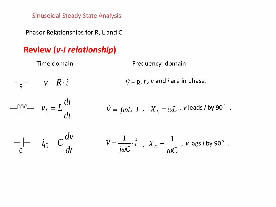
Review (v-I relationship)
Time domain Frequency domain
iRv IRV
ICj
V
1
ILjV dt
diLvL
dt
dvCiC
CXC
1
LX L ,
,
, v and i are in phase.
, v leads i by 90°.
, v lags i by 90°.
R
C
L
Sinusoidal Steady State Analysis
Phasor Relationships for R, L and C
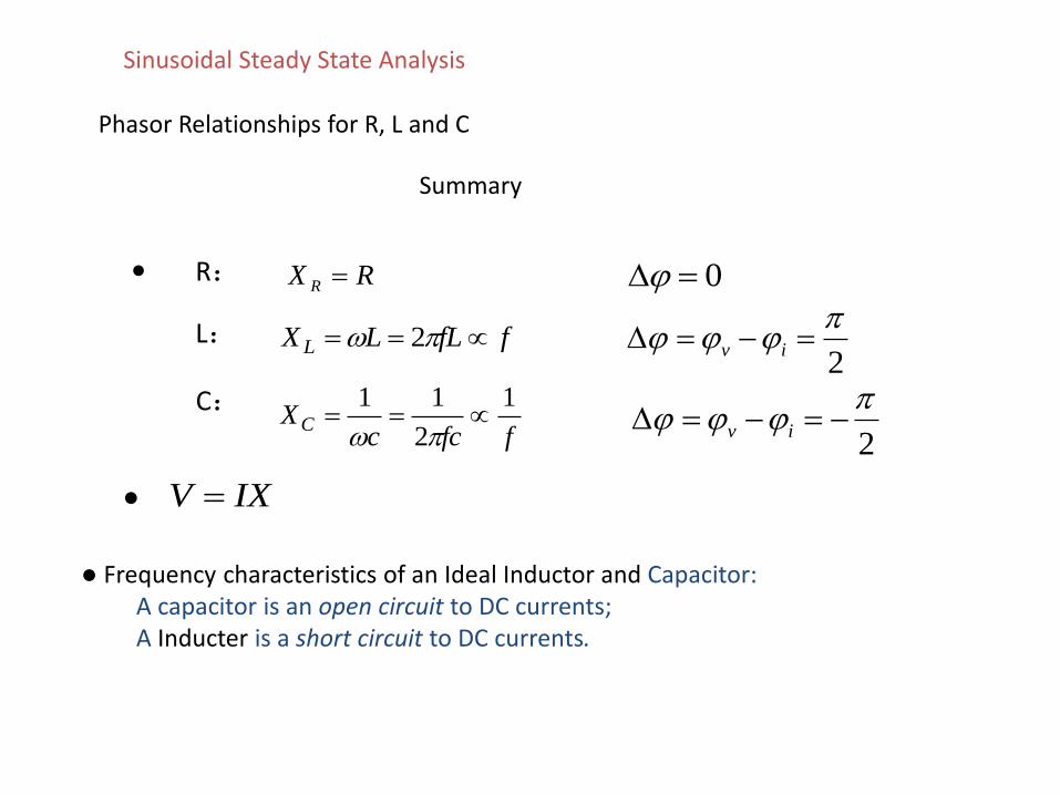
Summary
R: RX R 0
L: ffLLX L 22
iv
C:ffcc
XC
1
2
11
2
iv
IXV
Frequency characteristics of an Ideal Inductor and Capacitor:A capacitor is an open circuit to DC currents;A Inducter is a short circuit to DC currents.
Sinusoidal Steady State Analysis
Impedance
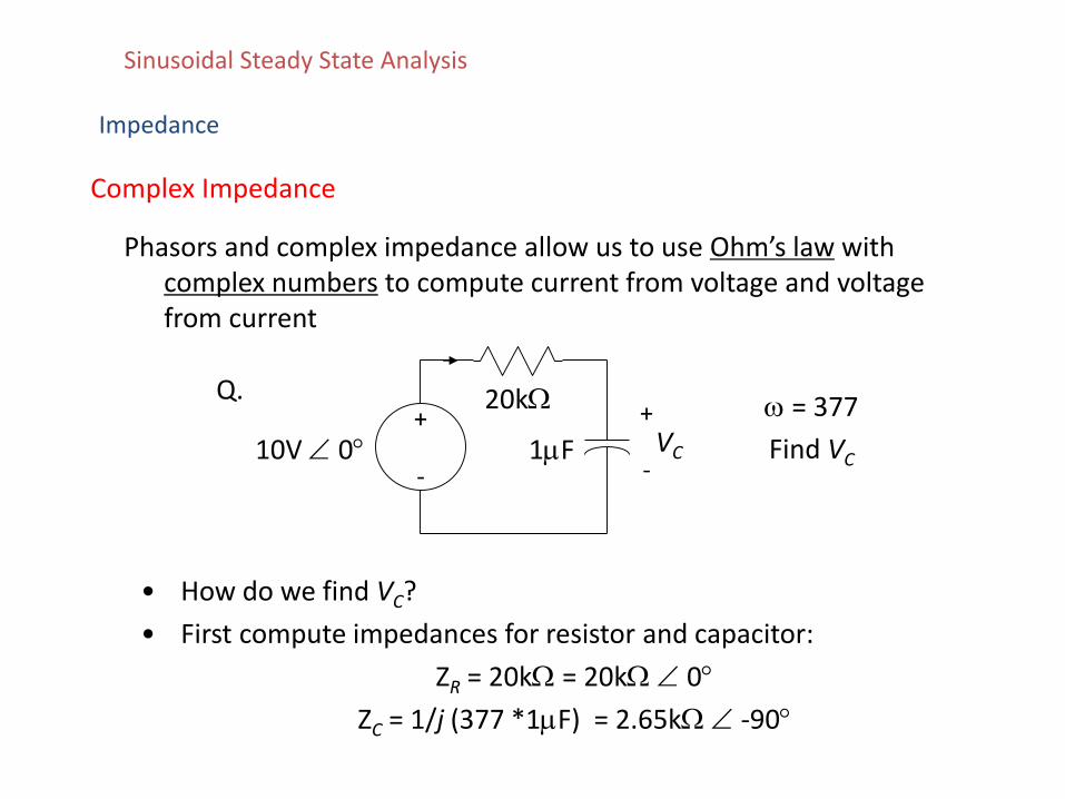
Complex Impedance
Phasors and complex impedance allow us to use Ohm’s law with complex numbers to compute current from voltage and voltage from current
20k+
-1F10V 0 VC
+
-
= 377
Find VC
Q.
• How do we find VC?
• First compute impedances for resistor and capacitor:
ZR = 20k = 20k 0
ZC = 1/j (377 *1F) = 2.65k -90
Sinusoidal Steady State Analysis
Impedance
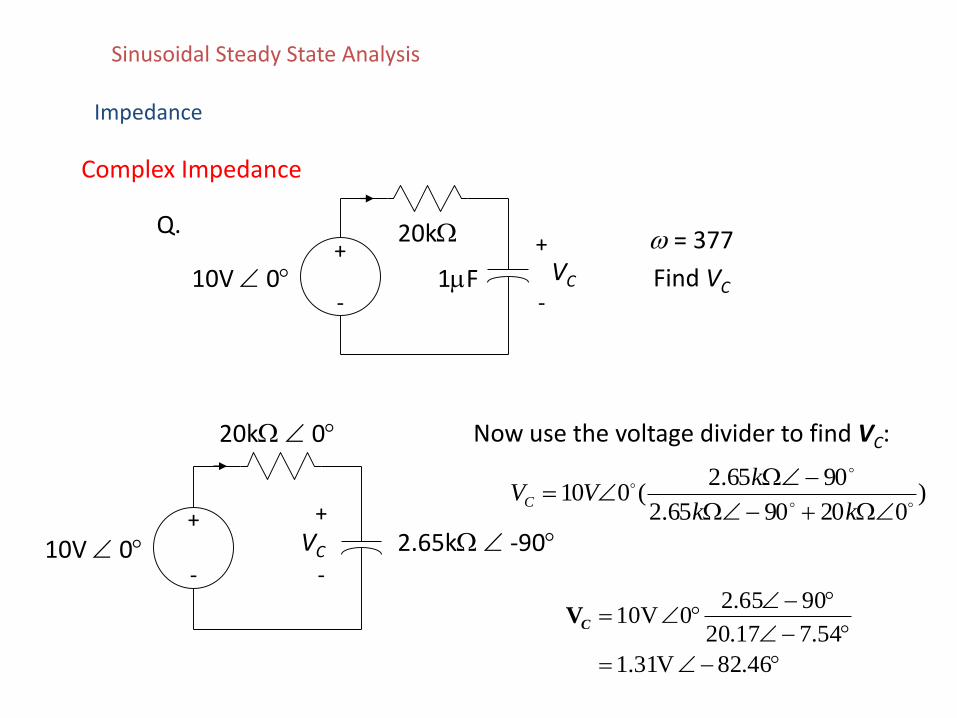
Complex Impedance
20k+
-1F10V 0 VC
+
-
= 377
Find VC
Q.
20k 0
+
-
2.65k -9010V 0 VC
+
-
Now use the voltage divider to find VC:
46.82 V31.1
54.717.20
9065.20 10VCV
)0209065.2
9065.2(010
kk
kVVC
Sinusoidal Steady State Analysis
Impedance
Impedance allows us to use the same solution techniquesfor AC steady state as we use for DC steady state.
• All the analysis techniques we have learned for the linear circuits are applicable to compute phasors
– KCL & KVL– node analysis / loop analysis– superposition– Thevenin equivalents / Norton equivalents– source exchange
• The only difference is that now complex numbers are used.
Complex Impedance
Sinusoidal Steady State Analysis
Impedance
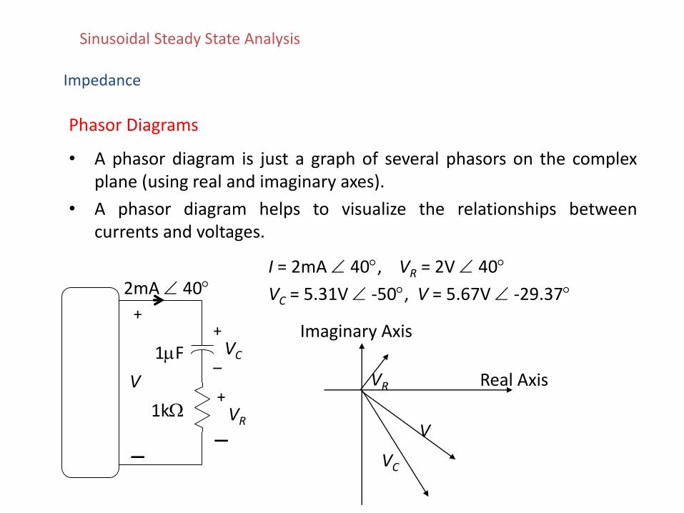
Phasor Diagrams
• A phasor diagram is just a graph of several phasors on the complexplane (using real and imaginary axes).
• A phasor diagram helps to visualize the relationships betweencurrents and voltages.
2mA 40
–
1F VC
+
–
1k VR
+
+
–
V
I = 2mA 40, VR = 2V 40
VC = 5.31V -50, V = 5.67V -29.37
Real Axis
Imaginary Axis
VR
VC
V
Sinusoidal Steady State Analysis
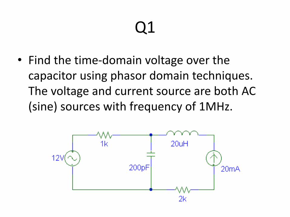
Q1
• Find the time-domain voltage over the capacitor using phasor domain techniques. The voltage and current source are both AC (sine) sources with frequency of 1MHz.

ANS:
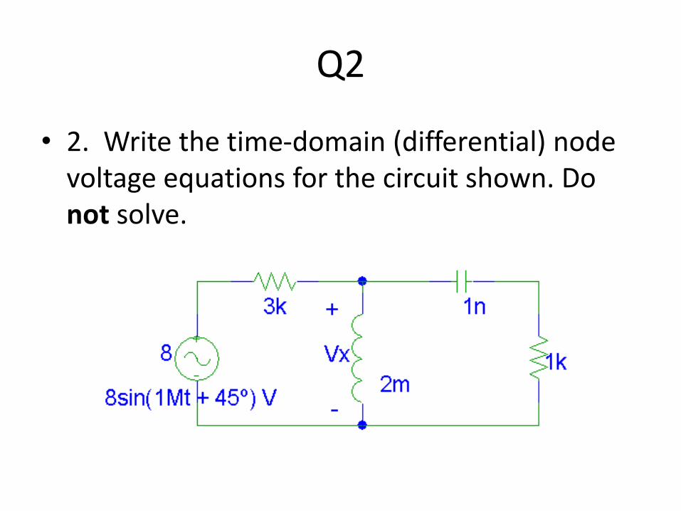
Q2
• 2. Write the time-domain (differential) node voltage equations for the circuit shown. Do not solve.

ANS:
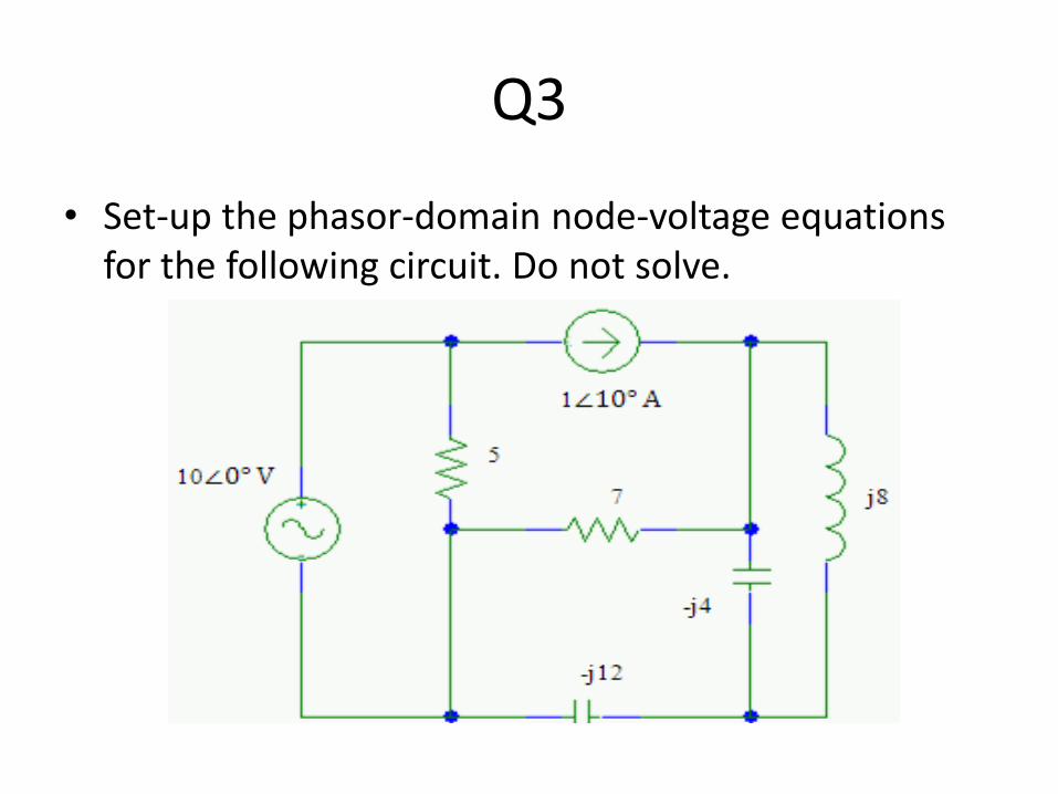
Q3
• Set-up the phasor-domain node-voltage equations for the following circuit. Do not solve.

ANS:
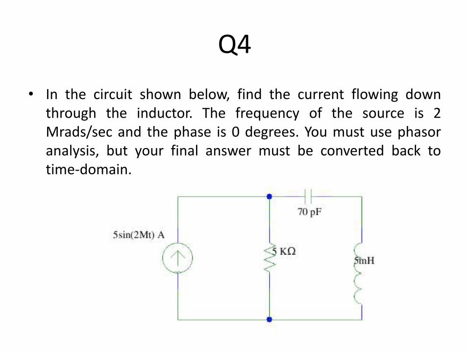
Q4
• In the circuit shown below, find the current flowing downthrough the inductor. The frequency of the source is 2Mrads/sec and the phase is 0 degrees. You must use phasoranalysis, but your final answer must be converted back totime-domain.

ANS:
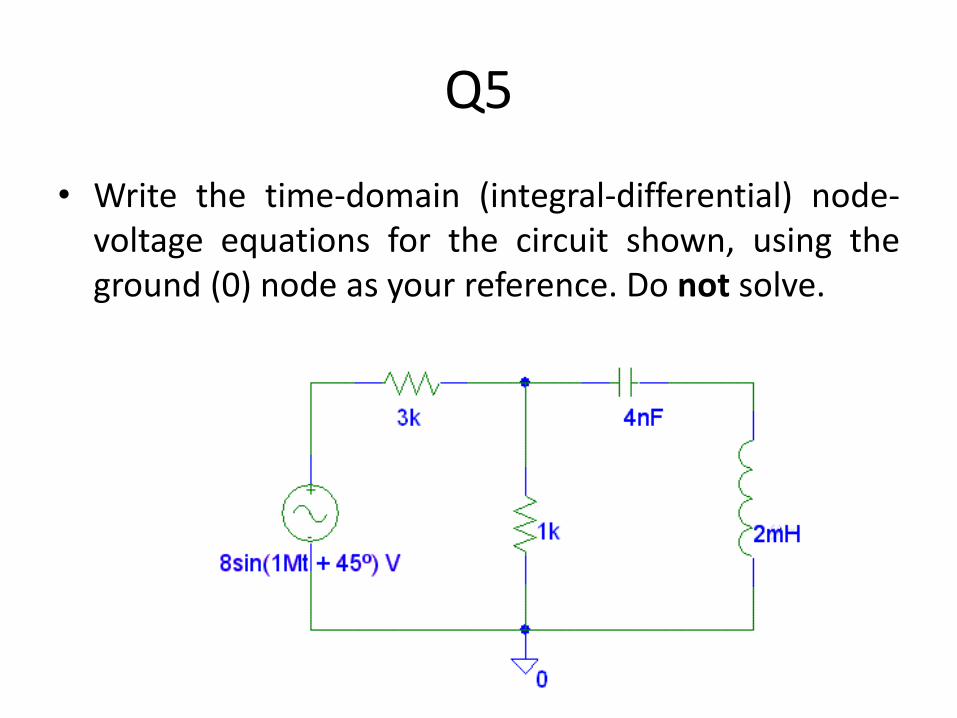
Q5
• Write the time-domain (integral-differential) node-voltage equations for the circuit shown, using theground (0) node as your reference. Do not solve.

Ans:
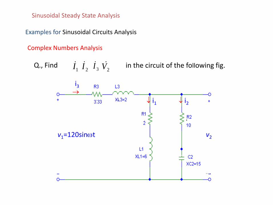
Examples for Sinusoidal Circuits Analysis
v1=120sint v2
i3
i1 i2
Q., Find1I
2I 3I2V in the circuit of the following fig.
Complex Numbers Analysis
Sinusoidal Steady State Analysis
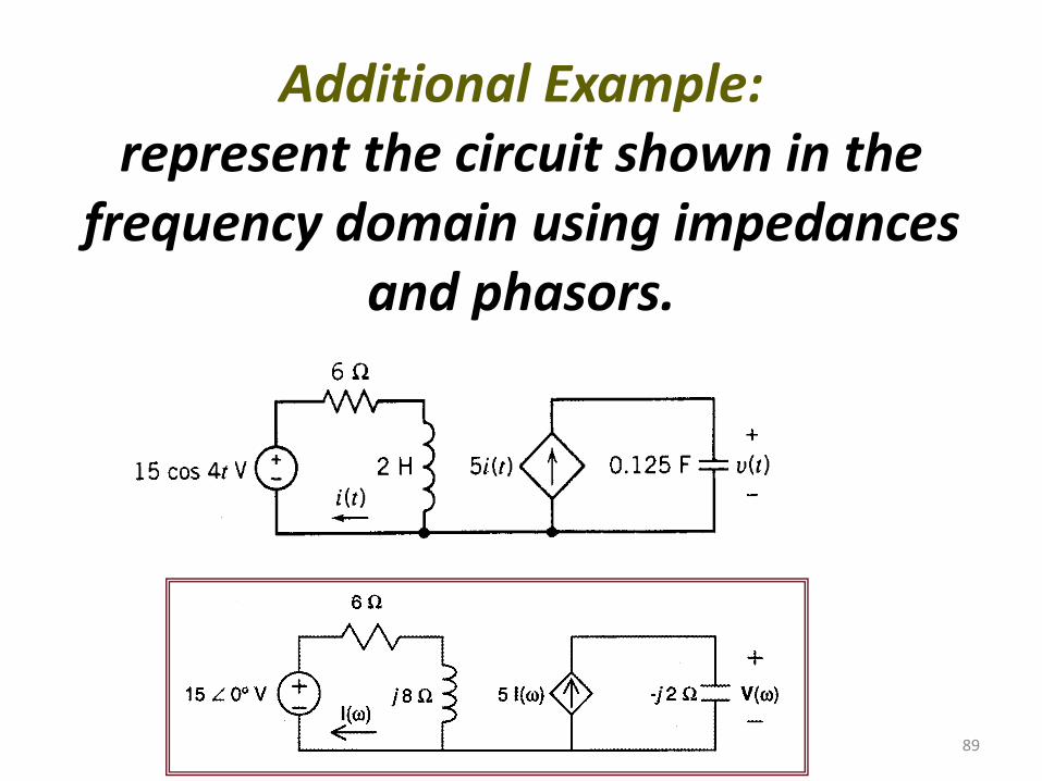
89
Additional Example: represent the circuit shown in the
frequency domain using impedances and phasors.
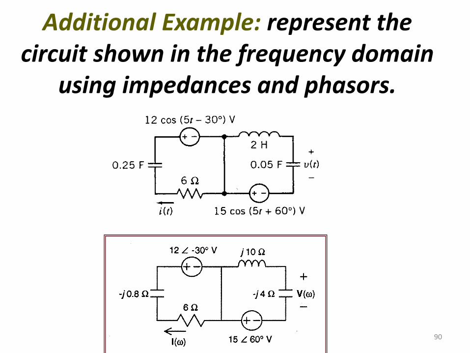
90
Additional Example: represent the circuit shown in the frequency domain
using impedances and phasors.
91
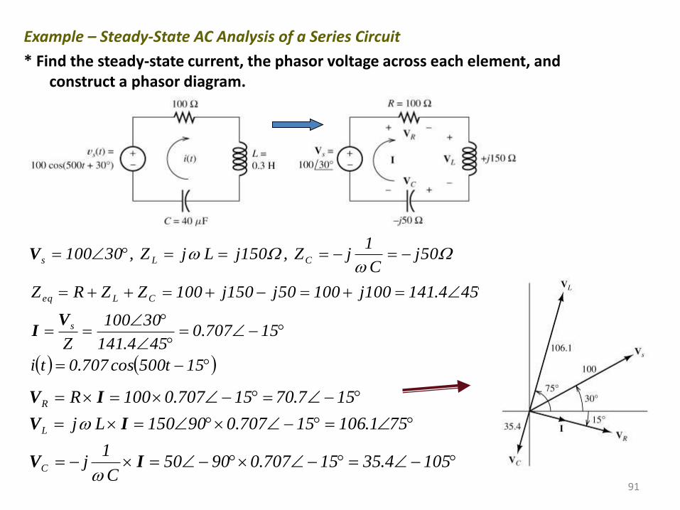
Example – Steady-State AC Analysis of a Series Circuit
* Find the steady-state current, the phasor voltage across each element, and construct a phasor diagram.
15t500cos707.0ti
15707.0454.141
30100
Z
454.141100j10050j150j100ZZRZ
50jC
1jZ ,150jLjZ ,30100
s
CLeq
CLs
VI
V
1054.3515707.09050C
1j
751.10615707.090150Lj
157.7015707.0100R
C
L
R
IV
IV
IV
92
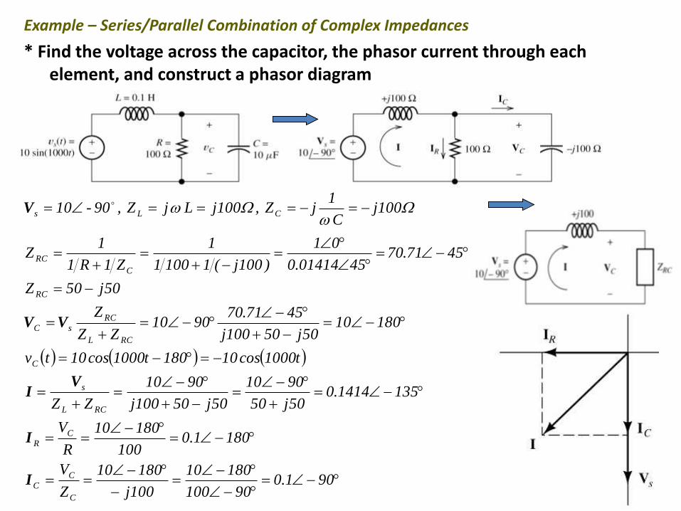
Example – Series/Parallel Combination of Complex Impedances
* Find the voltage across the capacitor, the phasor current through each element, and construct a phasor diagram
901.090100
18010
100j
18010
Z
V
1801.0100
18010
R
V
1351414.050j50
9010
50j50100j
9010
ZZ
t1000cos10180t1000cos10tv
1801050j50100j
4571.709010
ZZ
Z
50j50Z
4571.704501414.0
01
)100j(11001
1
Z1R1
1Z
100jC
1jZ ,100jLjZ ,90-10
C
C
C
CR
RCL
s
C
RCL
RC
sC
RC
C
RC
CLs
I
I
VI
VV
V
93
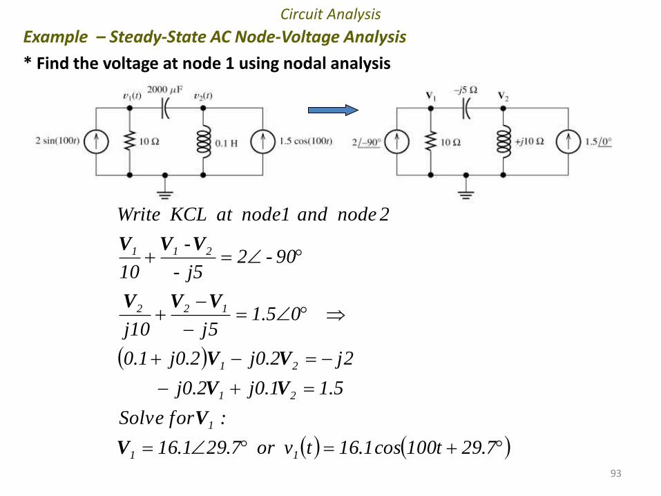
Circuit Analysis
Example – Steady-State AC Node-Voltage Analysis
* Find the voltage at node 1 using nodal analysis
7.29t100cos1.16tv or 7.291.16
: for Solve
5.11.0j2.0j
2j2.0j2.0j1.0
05.15j10j
90-2j5-
-
10
2 node and node1 at KCL Write
11
1
21
21
122
211
V
V
VV
VV
VVV
VVV
94
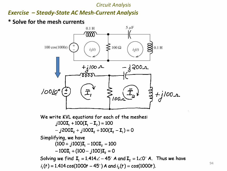
Circuit Analysis
Exercise – Steady-State AC Mesh-Current Analysis
* Solve for the mesh currents
Chap 2 – Mutual Inductance
• Dot Convention
In Practical
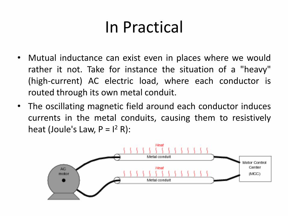
• Mutual inductance can exist even in places where we wouldrather it not. Take for instance the situation of a "heavy"(high-current) AC electric load, where each conductor isrouted through its own metal conduit.
• The oscillating magnetic field around each conductor inducescurrents in the metal conduits, causing them to resistivelyheat (Joule's Law, P = I2 R):
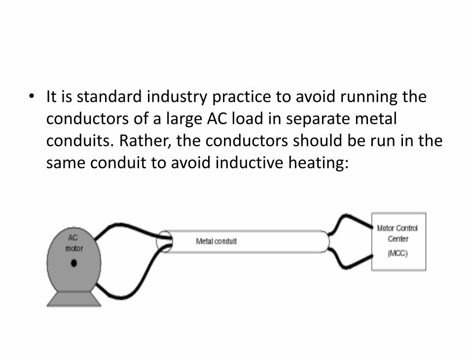
• It is standard industry practice to avoid running the conductors of a large AC load in separate metal conduits. Rather, the conductors should be run in the same conduit to avoid inductive heating:
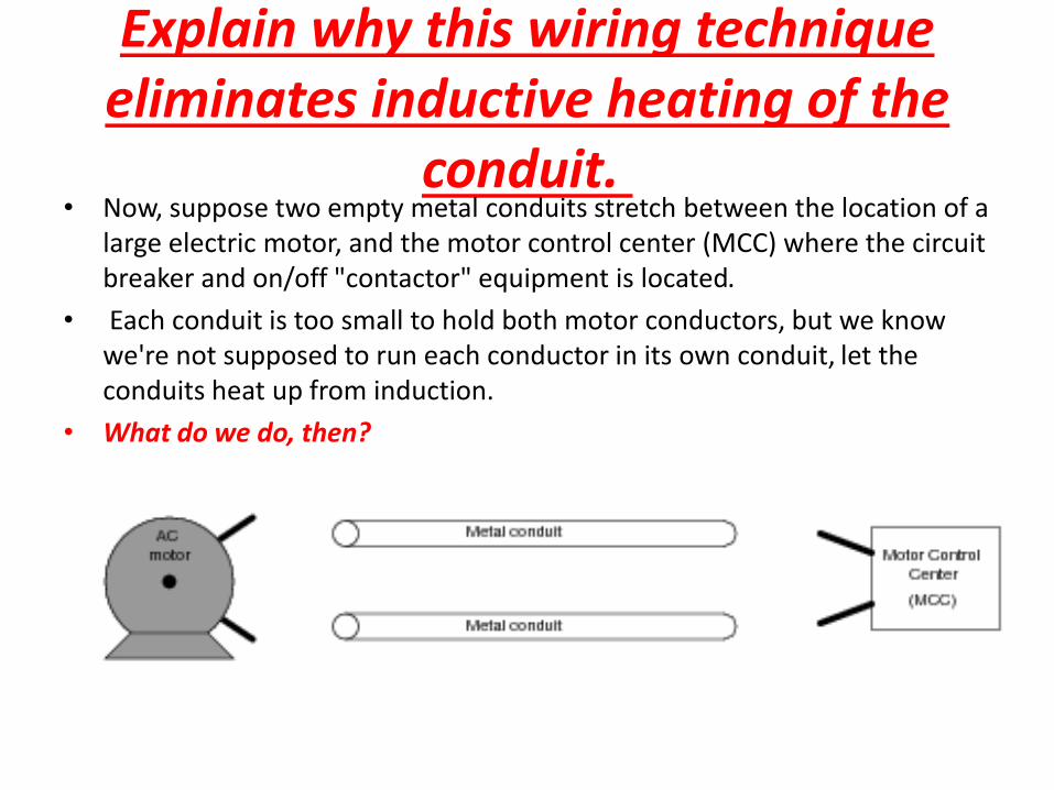
Explain why this wiring technique eliminates inductive heating of the
conduit.• Now, suppose two empty metal conduits stretch between the location of a
large electric motor, and the motor control center (MCC) where the circuit breaker and on/off "contactor" equipment is located.
• Each conduit is too small to hold both motor conductors, but we know we're not supposed to run each conductor in its own conduit, let the conduits heat up from induction.
• What do we do, then?
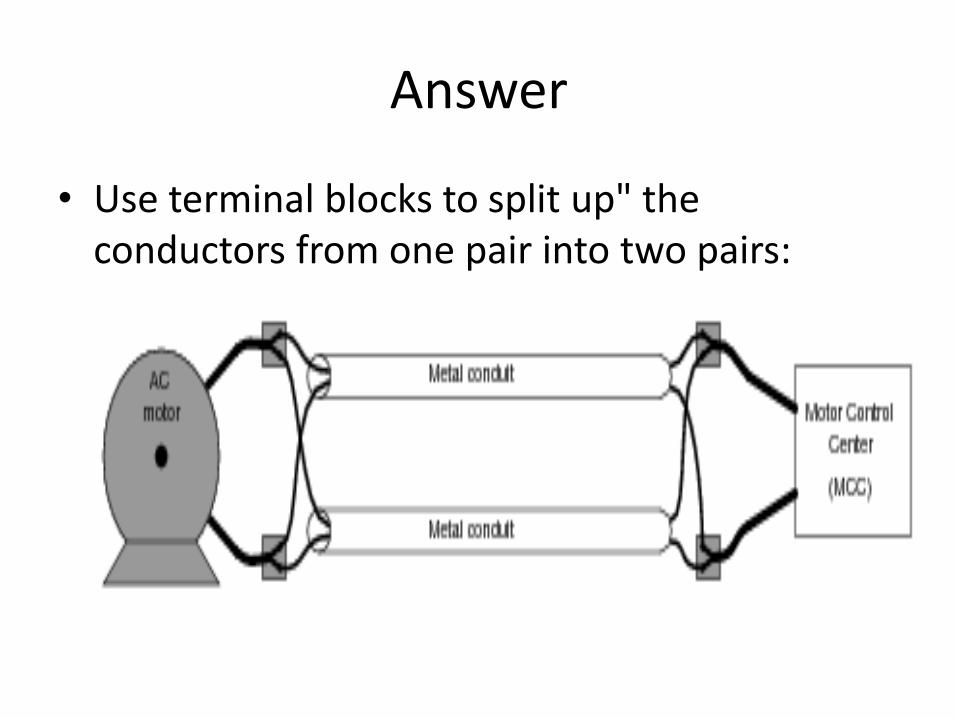
Answer
• Use terminal blocks to split up" the conductors from one pair into two pairs:
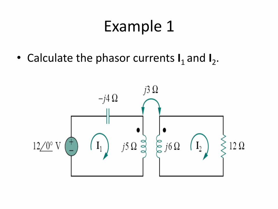
Example 1
• Calculate the phasor currents I1 and I2.
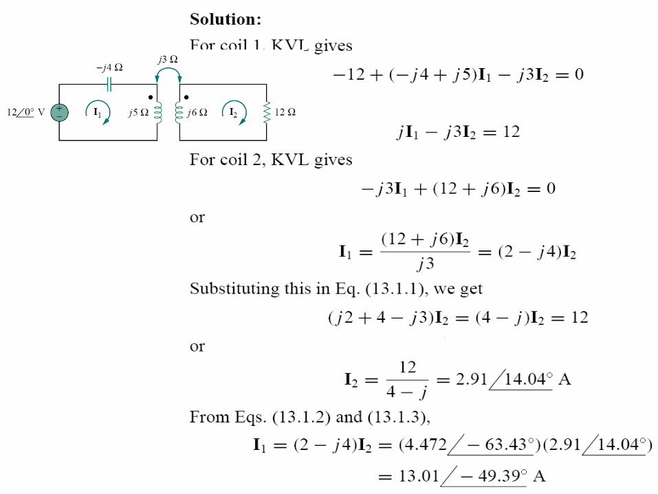
Solution
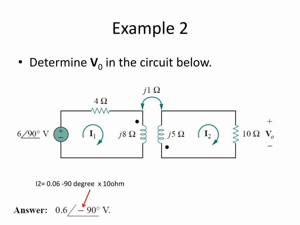
Example 2
• Determine V0 in the circuit below.
I2= 0.06 -90 degree x 10ohm
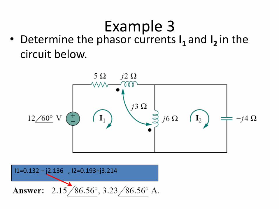
Example 3• Determine the phasor currents I1 and I2 in the
circuit below.
I1=0.132 – j2.136 , I2=0.193+j3.214
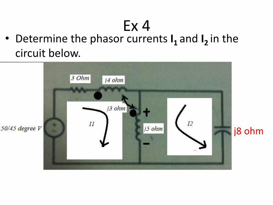
Ex 4• Determine the phasor currents I1 and I2 in the
circuit below.
-j8 ohm
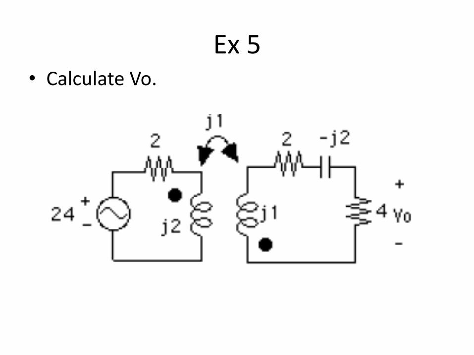
Ex 5• Calculate Vo.
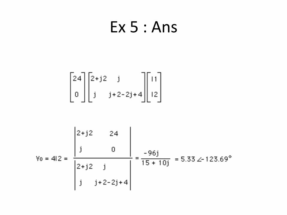
Ex 5 : Ans
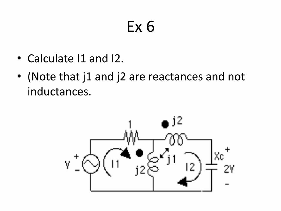
Ex 6
• Calculate I1 and I2.
• (Note that j1 and j2 are reactances and not inductances.
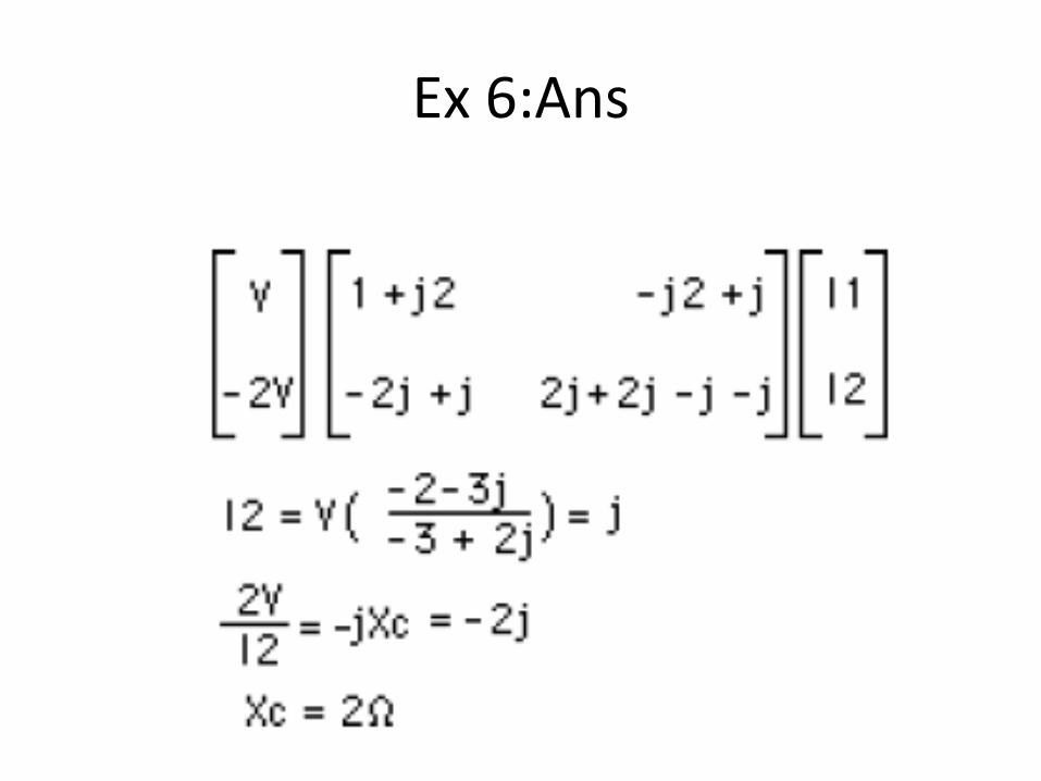
Ex 6:Ans
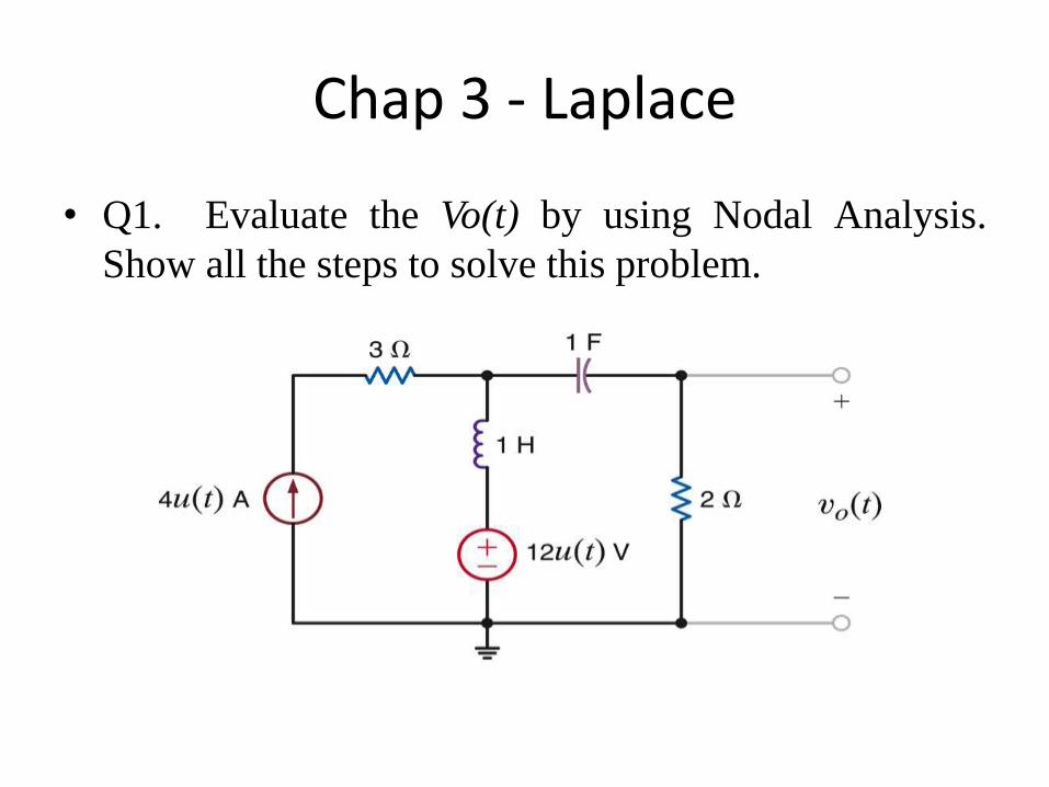
Chap 3 - Laplace
• Q1. Evaluate the Vo(t) by using Nodal Analysis.
Show all the steps to solve this problem.

Ans:
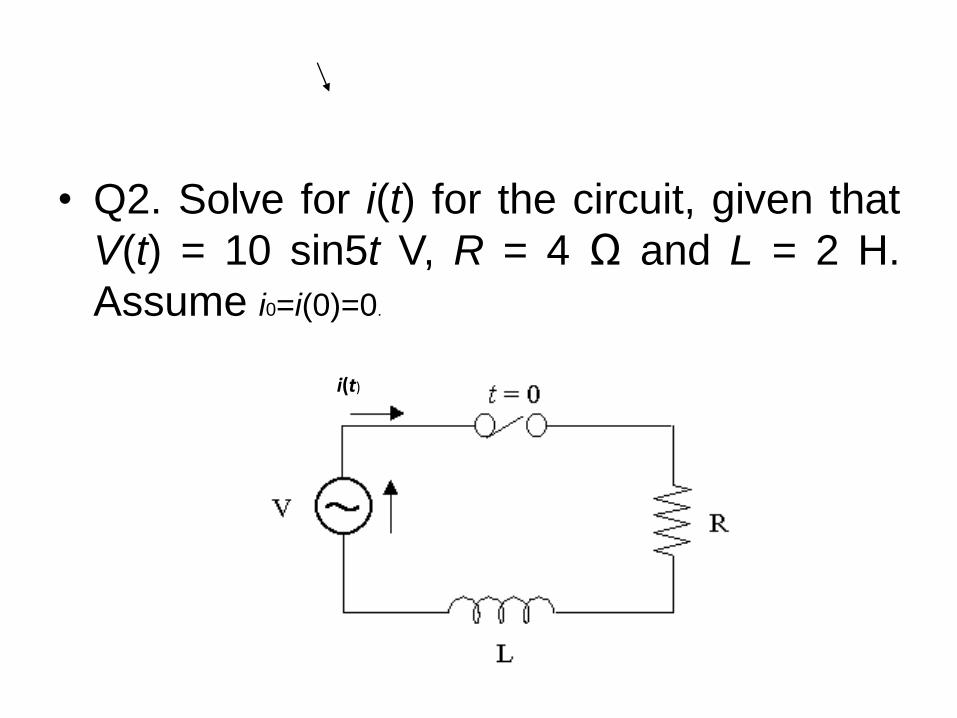
• Q2. Solve for i(t) for the circuit, given that
V(t) = 10 sin5t V, R = 4 Ω and L = 2 H.
Assume i0=i(0)=0.
i(t)

Ans
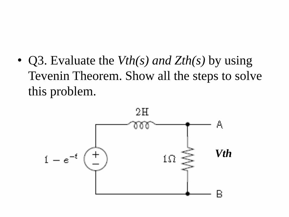
• Q3. Evaluate the Vth(s) and Zth(s) by using
Tevenin Theorem. Show all the steps to solve
this problem.
Vth

Ans:
Recommended


![Topic 1 ee201[1]](https://img.pdfslide.us/doc/110x75/588103d01a28ab22368b49d1/topic-1-ee2011.jpg)