www.marshindustries.co.uk
ECONOMICEFFICIENTSUSTAINABLESEWAGE TREATMENT
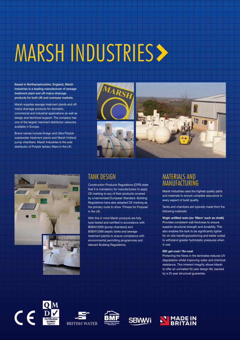
Based in Northamptonshire, England, MarshIndustries is a leading manufacturer of sewagetreatment plant and off-mains drainageproducts for both UK and overseas markets.
Marsh supplies sewage treatment plants and off-
mains drainage products for domestic,
commercial and industrial applications as well as
design and technical support. The company has
one of the largest merchant distributor networks
available in Europe.
Brand names include Ensign and Ultra Polylok
wastewater treatment plants and Marsh Holland
pump chambers. Marsh Industries is the sole
distributor of Polylok tertiary filters in the UK.
MARSH INDUSTRIES
MATERIALS AND MANUFACTURINGMarsh Industries uses the highest quality parts
and materials to ensure complete assurance in
every aspect of build quality.
Tanks and chambers are typically made from the
following materials:
Virgin unfilled resin (no ‘fillers’ such as chalk)Provides consistent wall thickness to ensure
superior structural strength and durability. This
also enables the tank to be significantly lighter
for on-site handling/positioning and better suited
to withstand greater hydrostatic pressures when
in use.
ISO gel-coat / flo-coatProtecting the fibres in the laminates reduces UV
degradation whilst improving water and chemical
resistance. This inherent integrity allows Marsh
to offer an unrivalled 50 year design life, backed
by a 25 year structural guarantee.
TANK DESIGNConstruction Products Regulations (CPR) state
that it is mandatory for manufacturers to apply
CE marking to any of their products covered
by a harmonised European Standard. Building
Regulations have also adopted CE marking as
the primary route to show ‘Fitness for Purpose’
in the UK.
With this in mind Marsh products are fully
type-tested and certified in accordance with
BSEN12050 (pump chambers) and
BSEN12566 (septic tanks and sewage
treatment plants) to ensure compliance with
environmental permitting programmes and
relevant Building Regulations.
01
SEWAGE TREATMENTWHAT ARE YOUR OPTIONS?
Choosing the right sewage treatment and disposal
method for your site is essential to ensure effective
long-term performance, protection of public health
and the environment, and compliance with relevant
legislation.
Sewage treatment and disposal can be provided by
a public (foul) sewer provider or by a private sewage
system. Developments proposing the use of private
systems are only usually acceptable where
connection to the public sewer is not possible and
must take account of the requirements of Building
Regulations which should be discussed with the
local Planning Authority at an early stage.
Before sewage effluent can be discharged to
‘controlled waters’ it must receive at least primary
and secondary treatment:
> For a discharge to ground the micro-organisms in
the soil provide the secondary treatment
> For a discharge to a water course the sewage
treatment must be provided by a Package
Sewage Treatment Plant (PSTP) or equivalent.
Site assessment*
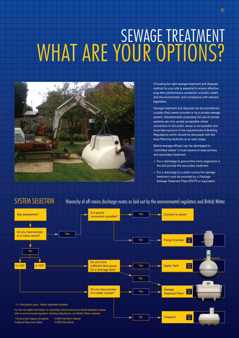
SYSTEM SELECTION Hierarchy of off-mains discharge routes as laid out by the environmental regulators and British Water
Do you have accessto a mains sewer?
Connect to sewer
Pump Chamber
Septic Tank
Sewage Treatment Plant
Cesspool
Yes
No
Is a gravityconnection possible?
Yes
No
Yes
No
Yes
No
Do you havesufficient land spacefor a drainage field?
Do you have accessto a water course?
V>100* V<100*
* V = Percolation value - Marsh datasheet available
For the very latest information on discharge criteria and environmental legislation pleaserefer to environmental regulators, Building Regulations, and British Water websites.
1 Environment Agency (England)2 Natural Resources Wales
page
02
page
08
page
04
page
093 NIEA (Northern Ireland)4 SEPA (Scotland)
PUMP CHAMBERSWhen discharge to mains is required, but to do so by gravity isimpractical, a pump chamber system will be needed. Althoughavailable as floor-mounted units for indoor applications such asbasements, the vast majority are installed outdoors at levels tosuit on-site conditions and topography.
The Marsh range incorporates systems for pumping surface water
or domestic sewage to mains, septic/PSTP effluent to drainage
fields/watercourses, and bespoke systems for larger domestic and
industrial applications.
> Where foul water drainage from a domestic property is to be pumped to
the mains the effluent receiving chamber should be sized to contain
24-hour inflow to allow for disruption in service, the minimum daily
discharge being taken as 150 litres per person per day.
> For other building types the capacity of the receiving chamber should be
based on the calculated daily demand of the water intake for the building,
or when only a proportion of the foul sewage is to be pumped then the
capacity should be based pro-rata.
> If the sewer is to be ‘adopted’ by a local water authority, please contact
Marsh Industries as Sewers for Adoption (SFA) specification and
additional local authority related criteria may apply.
PUMP CHAMBER BENEFITS> Designed to BSEN12050 for structural strength and water-tightness and to BSEN752 to comply with hydrostatic and electrical requirements
> Smooth internal walls and integral pump well improves pump efficiency and eliminates ‘dead spots’ which can lead to odours and septicity
> Pre-assembled pipework for fully automatic operation (pump/control equipment separate).
> Heavy duty (industrial) ‘peardrop’ floats and Lowara (Xylem) pumps throughout ensure robust, reliable design and maximum efficiency of
pump with minimal clogging or wear
> Unique ‘keying-in’ lip to assist anchoring into concrete surround
> High level alarm as standard
> Variable invert depths and orientations to suit individual site conditions
FOR PUMPING SEWAGE AND WATER TO MAINS
02
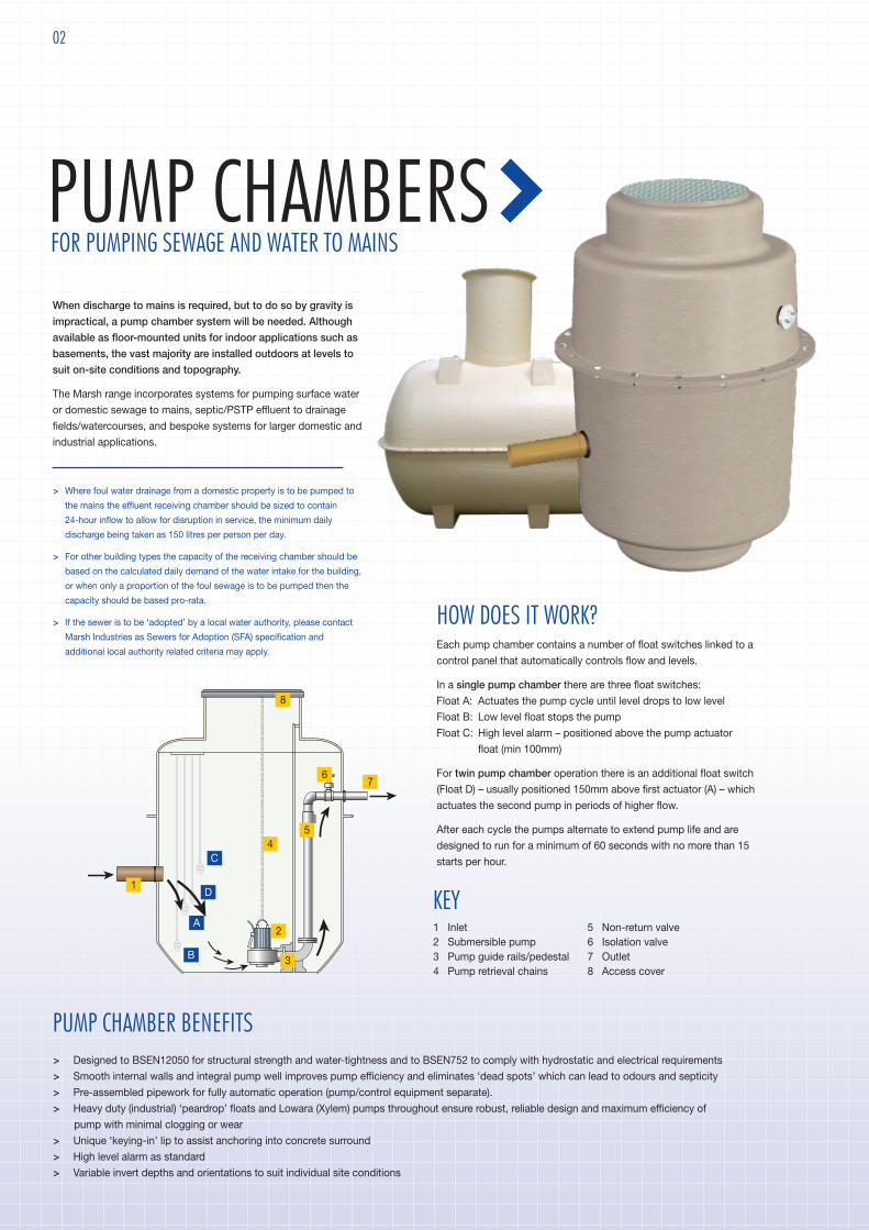
HOW DOES IT WORK?Each pump chamber contains a number of float switches linked to a
control panel that automatically controls flow and levels.
In a single pump chamber there are three float switches:Float A: Actuates the pump cycle until level drops to low level
Float B: Low level float stops the pump
Float C: High level alarm – positioned above the pump actuator
float (min 100mm)
For twin pump chamber operation there is an additional float switch(Float D) – usually positioned 150mm above first actuator (A) – which
actuates the second pump in periods of higher flow.
After each cycle the pumps alternate to extend pump life and are
designed to run for a minimum of 60 seconds with no more than 15
starts per hour.
A
B
C
D1
1 Inlet 2 Submersible pump 3 Pump guide rails/pedestal 4 Pump retrieval chains
5 Non-return valve 6 Isolation valve 7 Outlet 8 Access cover
3
2
45
67
8
KEY

Single pump system Typical section
Inle
t in
vert
Hei
ght
Width
Twin pump system
Ground level
Inlet Inlet Inlet
Outlet invert
Length Width
Heig
ht
500
View on outlet endTypical side elevation
Inletinvert
Ground level
Pumpedoutlet
HORIZONTAL SPECIFICATIONS For larger housing projects, and commercial/industrial developments
VERTICAL SPECIFICATIONS For housing projects and small commercial developments
03
All dimensions in mm
Model Diameter Height Inlet Outlet Storage below Total storageInvert Ø Invert Ø invert Litres
Mini 600 1100 500 110 300 63 120 234
Midi 600 1500 500 110 300 63 280 421
Maxi 600 2000 500 110 300 63 421 561
CPS1 1100 1100 500 110 300 63 470 867
CPS2 1100 1500 700 110 300 63 780 1183
CPS3 1100 2200 900 110 300 63 1025 1735
CPS4 1100 2600 900 110 300 63 1340 2050
CPS5 1700 2100 900 110 300 63 2440 3700
CPS6 1700 3400 900 110 300 63 4000 6000
Model Length Width Height Inlet Outlet Total storageInvert Ø Invert Ø Litres
AT2800 3000 1250 1750 800 110 300 63 2800
AT3800 4000 1250 1750 800 110 300 63 3800
AT4500 2650 1600 2100 800 110 300 63 4500
AT6000 2950 1900 2400 800 160 300 63 6000
AT8000 3640 1900 2400 800 160 300 63 8000
AT10000 4200 1900 2400 800 160 300 63 10000
AT12000 5200 1900 2400 800 160 300 63 12000
AT14000 5840 1900 2400 800 160 300 63 14000
AT16000 6700 1900 2400 800 160 300 63 16000
AT18000 7500 1900 2400 800 160 300 63 18000
AT20000 8100 1900 2400 800 160 300 63 20000
Model Length Width Height Inlet Outlet Total storageInvert Ø Invert Ø Litres
Marmicro Single 700 740 840 350 110 250 50 270
Marmicro Twin 1270 740 840 350 110 250 50 550
MARMICRO SPECIFICATIONS For small flows from a single dwelling
Plan viewPlan view
Marmicro TwinMarmicro Single
Typical side elevation
Hei
ght
Length
Wid
th
Length
All pump chambers are available for dirty water (DW) orsewage (SW), in single pump (SP) and twin pump (TP)configurations.
Pump chambers are usually bespoke. The dimensionsgiven on this page are for guidance only
All dimensions in mm
All dimensions in mm

04
Package Sewage Treatment Plant's (or PSTP's) areoften a suitable option where groundwater in thesurrounding environment is vulnerable, drainage fieldpercolation values are restrictive, or direct dischargeto watercourse or surface water sewer is the prefereddischarge method.
In addition to the anaerobic digestion taking place in the
primary settlement tank (as septic tanks) the Ensign unit
allows the clarified water to pass into a second
'aeration' chamber where it is treated to remove the
dissolved constituents. Here aerobic bacteria,
supported by diffused air and mobile media, ensure full
treatment is achieved before the treated effluent (and
'sloughed off' bacteria) flow to a final settlement
chamber prior to discharge.
> PSTP's should be sized using the latest version of
British Water Flows & Loads which provides
detailed information on sewage production figures
and sizing calculations
> Regulatory authorities for the control of pollution
in the UK normally require treatment plants
conforming to BSEN12566:3 to be demonstrated
as capable of producing a minimum effluent
discharge quality of 20:30:20 (Biochemical
ENSIGN PACKAGESEWAGE TREATMENT PLANTINTENSIVE BIOLOGICAL PROCESSING FOR OFF-MAINS WASTEWATER
KEY1 Inlet 2 Primary chamber 3 Aeration chamber 4 Compressor (external on shallow and
pumped units) 5 Diffuser 6 Final (or ‘humus’) chamber 7 Recirculation to primary chamber 8 Outlet 9 Manway access
Oxygen Demand;Suspended Solids: Ammoniacal
Nitrogen in mg/ltr), although in certain areas more
stringent site-specific qualities may be required
> No surface water should enter the system as this
can reduce the system's capacity and cause
solids to be flushed out which may prematurely
block drainage field or cause pollution
> As with septic tanks sludge should be removed
annually or in line with manufacturers instructions
1
3
2
4
5
6
78
9

05
ENSIGN BENEFITS> Tested to BSEN12566:3 and CE-marked to ensure compliance with latest environmental and Building Regulations requirements
> Class-leading effluent quality of 11.5:19.2:8.4 (BOD:SS:NH4) ensures discharges well within national consent standards > Three chamber system correctly sized for separation and retention of solids improves final effluent quality
> Standard or shallow options enable suitability for all site conditions (including driveways - subject to plinth/surround to prevent superimposed loadings)
> Shallow option ideal for groundworks involving bedrock or high water table as the low profile allows for safe, cost effective installation
> Low energy compressors ensure minimal running, maintenance and servicing costs
> High specification bio-media (310m3 per m2) and membrane diffusers ensure even circulation to eliminate 'dead spots'
> Internal recirculation (from final to primary chamber) continues treatment process to provide higher effluent quality whilst balancing flow over 24 hour
period or periods of intermittent use
> Integral lifting eyes for improved on-site handling
> Unique ‘keying-in’ lip to assist anchoring into granular or concrete surround
> Optional extras include patented Polylok filter to further reduce suspended solids and extend life of drainage field; extensions for deep installations;
pumped outlets for sites with adverse levels; and many more
Ground level
View on inlet end Typical side elevation
T
Length
Height
Typical plan view
T
Inlet
View on outlet end
Outlet
Outletinvert
O
Inletinvert
Width
ENSIGN SPECIFICATIONS
Ground level
Typical side elevation
L
View on outlet end
T
Typical plan view
I
Outletinvert
Inletinvert
Length Width
Height
View on inlet end
ENSIGN SHALLOW SPECIFICATIONS
All dimensions in mm
All dimensions in mm
Model Length Width Height Inlet OutletInvert Ø Invert Ø
6 2602 1650 1935 550 110 625 110
10 2602 1650 1935 550 110 625 110
12 2860 1912 2139 550 110 625 110
16 2860 1912 2284 720 110 800 110
20 3650 1912 2284 720 160 800 160
25 3650 1912 2284 770 160 850 160
30 4550 1912 2284 770 160 850 160
35 4550 1912 2284 770 160 850 160
40 5200 1912 2284 770 160 850 160
45 5200 1912 2284 770 160 850 160
50 5200 1912 2284 770 160 850 160
Model Length Width Height Inlet OutletInvert Ø Invert Ø
6 2860 1912 1600 500 110 575 110
10 2860 1912 1600 500 110 575 110
12 2860 1912 1600 500 110 575 110
16 3400 1912 1600 500 110 575 110
20 4550 1912 1600 500 160 575 160
25 4550 1912 1600 500 160 575 160
30 5500 1912 1600 500 160 575 160
35 5500 1912 1600 500 160 575 160
06
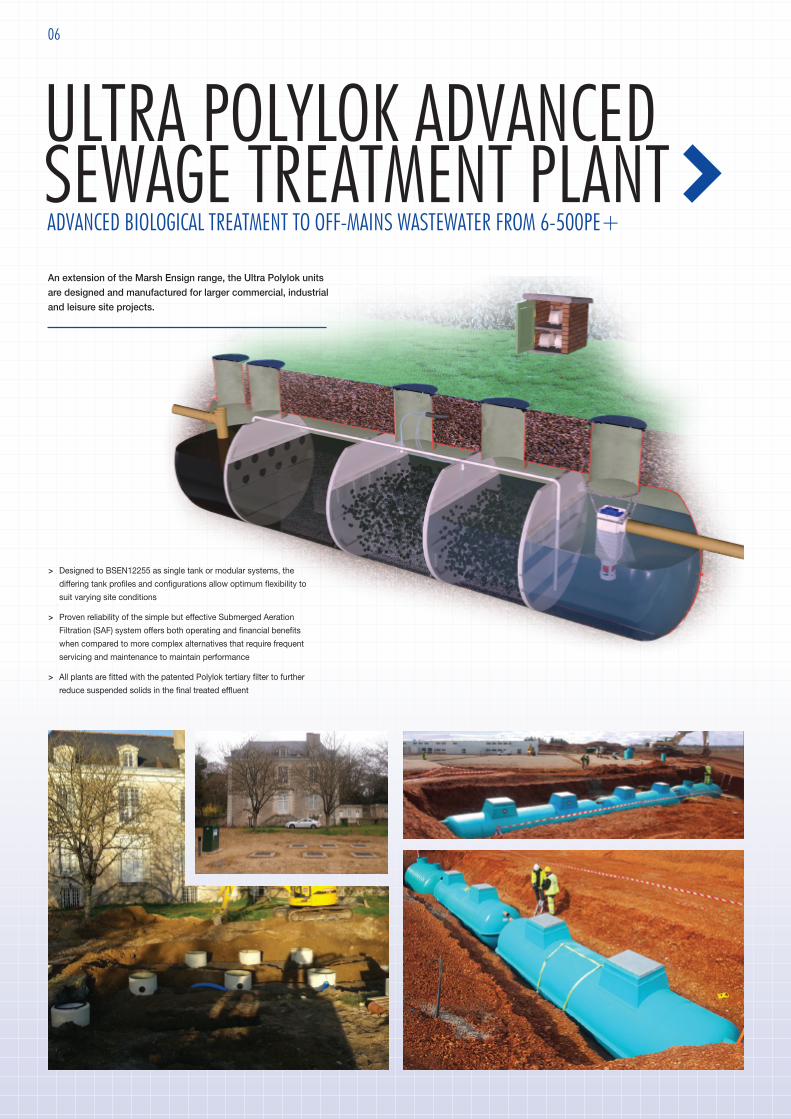
An extension of the Marsh Ensign range, the Ultra Polylok unitsare designed and manufactured for larger commercial, industrialand leisure site projects.
ULTRA POLYLOK ADVANCEDSEWAGE TREATMENT PLANTADVANCED BIOLOGICAL TREATMENT TO OFF-MAINS WASTEWATER FROM 6-500PE+
> Designed to BSEN12255 as single tank or modular systems, the
differing tank profiles and configurations allow optimum flexibility to
suit varying site conditions
> Proven reliability of the simple but effective Submerged Aeration
Filtration (SAF) system offers both operating and financial benefits
when compared to more complex alternatives that require frequent
servicing and maintenance to maintain performance
> All plants are fitted with the patented Polylok tertiary filter to further
reduce suspended solids in the final treated effluent

07
Specifically designed for disinfecting the effluent from residential andcommercial aerobic treatment plants by destroying viruses, parasites andpathogenic bacteria.
The Ultra Polylok UV chambers can be installed as part of a Marsh Ultra Polylok
sewage treatment plant or as a stand-alone plant to further improve the effluent
from an existing sewage treatment plant.
ULTRA POLYLOK UV FILTERULTRA-VIOLET DISINFECTION
Available for domestic or commercial sites the Marsh Phoslok is single pieceplant which adds timed doses of a coagulant to treated effluent to furtherremove phosphates.
Easily installed downstream from a sewage treatment plant, this tertiary treatment
option is the best available method to prevent eutrophication in sensitive
discharge locations such as protected waters.
PHOSLOKTERTIARY PHOSPHATE TREATMENT
Through a system of internal baffles and polylok filters,Marsh grease traps aid the performance of sewagetreatment plants by preventing fats, oils and greases fromentering the drainage channel.
GREASE TRAPSTO AID THE PERFORMANCE OF SEWAGE TREATMENT PLANTS
SEPTIC TANK BENEFITS> Tested to BSEN12566:1 and CE-marked to ensure compliance with latest
environmental and Building Regulations requirements
> Traditional 'onion-style' tanks for standard installations
> Low profile versions for high water table or hard rock site conditions
> Heavy duty shell as standard to enable installation in all ground conditions
> Integral lifting eyes for improved on-site handling
> Unique ‘keying-in’ lip to assist anchoring into granular or concrete surround
> Pedestrian cover and frame included as standard
> Additional ‘Green Filter’ range incorporating patented Polylok filter on outlet
to reduce suspended solids, improving effluent quality and prolonging
drainage field life
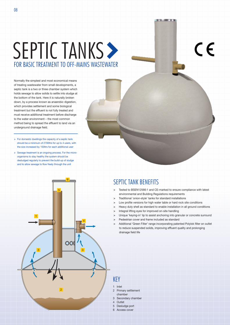
SEPTIC TANKSFOR BASIC TREATMENT TO OFF-MAINS WASTEWATER
08
Normally the simplest and most economical means
of treating wastewater from small developments, a
septic tank is a two or three chamber system which
holds sewage to allow solids to settle into sludge at
the bottom of the tank. Here it is naturally broken
down, by a process known as anaerobic digestion,
which provides settlement and some biological
treatment but the effluent is not fully treated and
must receive additional treatment before discharge
to the water environment – the most common
method being to spread the effluent to land via an
underground drainage field.
> For domestic dwellings the capacity of a septic tank
should be a minimum of 2700ltrs for up to 4 users, with
the size increased by 150ltrs for each additional user
> Sewage treatment is an ongoing process. For the micro-
organisms to stay healthy the system should be
desludged regularly to prevent the build-up of sludge
and to allow sewage to flow freely through the unit
KEY1 Inlet 2 Primary settlement
chamber 3 Secondary chamber 4 Outlet 5 Desludge port 6 Access cover
1
3
2
4
5
6
3

09
A cesspool is a covered, watertight tank used for storing sewage. It has no outlet andrelies on road transport for the removal of raw sewage. No treatment is involved.
> For domestic applications cesspools should have a capacity below the level of the invert of at least
18,000ltrs for two users, and should be increased by 6800ltrs for each additional user. Cesspools for
commercial premises have no such restrictions
> Installation of a high level alarm is recommended to indicate when it is nearly full
> Whoever empties your cesspool (or septic/PSTP) should be a registrered Waste Carrier and hold a
current discharge licence from the local water authority
> Use of cesspool is not permitted in Scotland
CESSPOOLSFOR BASIC STORAGE AND DISPOSAL OF OFF-MAINS WASTEWATER
Typical side elevation
Diameter
Hei
ght
Outletinvert
Ground level
Inletinvert
Typical side elevation View on outlet end
Inletinvert
Outletinvert
Ground level
Hei
ght
500
WidthLength
Size Dia Height Inlet OutletInvert Ø Invert Ø
2800L 1870 2780 1000 110 1040 1103800L 2075 3000 1000 110 1040 1104500L 2196 3100 1000 110 1040 110
Size Length Width Height Inlet OutletInvert Ø Invert Ø
2800L 3000 1250 1750 500 110 800 110
3800L 4000 1250 1750 500 110 800 110
4500L 2650 1600 2100 500 110 800 110
6000L 2950 1900 2400 500 160 800 160
8000L 3640 1900 2400 500 160 800 160
10000L 4200 1900 2400 500 160 800 160
12000L 5200 1900 2400 500 160 800 160
14000L 5840 1900 2400 500 160 800 160
16000L 6700 1900 2400 500 160 800 160
18000L 7500 1900 2400 500 160 800 160
20000L 8100 1900 2400 500 160 800 160
STANDARD SEPTIC TANK SPECIFICATIONS
HORIZONTAL SEPTIC TANK SPECIFICATIONS
Model Length Width Height InletInvert Ø
AT2800 3000 1250 1750 500 110
AT3800 4000 1250 1750 500 110
AT4500 2650 1600 2100 500 110
AT6000 2950 1900 2400 500 160
AT8000 3640 1900 2400 500 160
AT10000 4200 1900 2400 500 160
AT12000 5200 1900 2400 500 160
AT14000 5840 1900 2400 500 160
AT16000 6700 1900 2400 500 160
AT18000 7500 1900 2400 500 160
AT20000 8100 1900 2400 500 160
CESSPOOL SPECIFICATIONS
All dimensions in mm All dimensions in mm
All dimensions in mm

www.marshindustries.co.uk
MARSH INDUSTRIESUnits 3-13 Addington Park Industrial EstateLittle Addington, KetteringNorthamptonshire NN14 [email protected]+44 (0)1933 654582
MI-ST-0914-B
Recommended