ECE 353Introduction to Microprocessor Systems
Michael Schulte
Week 12

Administrative MattersHomework #6 due Friday, May 9th
Reading for week 12 (switches, keypads, and displays) Textbook 7.6-7.10 Supplement #5 (Learn@UW)
Final exam on Saturday, May 17th from 7:45am to 9:45am in 3418 EH Cumulative exam covering Modules 1-
6 More details coming soon

TopicsDigital Inputs Mechanical switches Keypads and keyboards Rotary encoders
Displays LED displays LCD displays

Mechanical SwitchesTypes of switches Poles Throws Contact action
Converting switch position to a logic levelMechanical contact bounceDebouncing in Hardware RS latch Integrator/Schmitt-trigger Dedicated ICs (MAX6816/7/8)
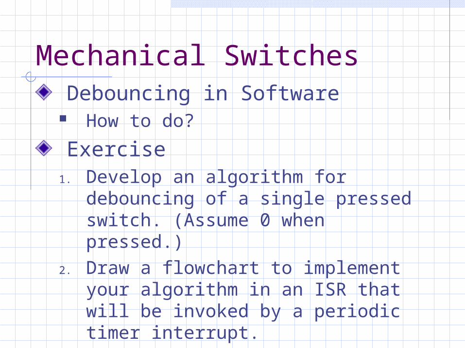
Mechanical SwitchesDebouncing in Software
How to do?
Exercise1. Develop an algorithm for
debouncing of a single pressed switch. (Assume 0 when pressed.)
2. Draw a flowchart to implement your algorithm in an ISR that will be invoked by a periodic timer interrupt.
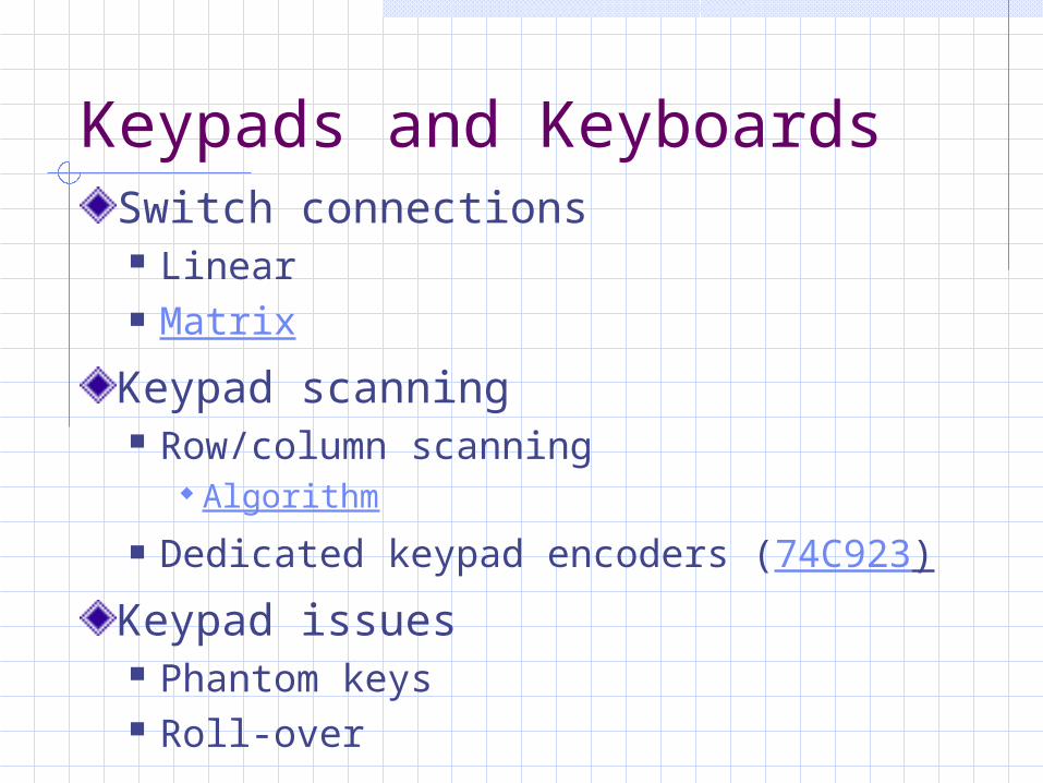
Keypads and KeyboardsSwitch connections Linear Matrix
Keypad scanning Row/column scanning
Algorithm Dedicated keypad encoders (74C923)
Keypad issues Phantom keys Roll-over
Rotary EncodersConvert angular position to digital valueEncoding schemes Quadrature Encoders Absolute Encoders Indexed Encoders
Interfacing Software
Using interrupts Hardware
Design logic or use dedicated devices

LED DisplaysCharacteristicsDriver requirementsDisplay types Drivers
Multiplexed displays Driver circuits Refresh rate Duty cycle Intensity control Display Driver ICs
LED ISR algorithm and routine

LCD Display Characteristics
Numeric, text and/or graphic displaysExtremely low powerPassiveTemperature sensitiveComplex drivers required to create segment waveforms Require no net DC offset on segments –
on single polarity systems this adds to driver complexity

LCD Technologyhttp://en.wikipedia.org/wiki/Liquid_crystal_display
Natural state Molecules are arranged in a loosely ordered
fashion with their long axes parallel.
Aligned state When coming into contact with a finely
grooved surface (alignment layer), molecules line up in parallel along the grooves.

LCD TechnologyWhen liquid crystals are sandwiched between upper and lower plates, they line up with grooves pointing in directions 'a' and 'b,' respectively. The molecules along the upper plate point in direction 'a' and those along the lower plate in direction 'b,' thus forcing the liquid crystals into a twisted structural arrangement. (figure shows a 90-degree twist) (TN type liquid crystal)

LCD TechnologyLight passes through liquid crystals, following the direction in which the molecules are arranged. When the molecule arrangement is twisted 90 degrees as shown in the figure, the light also twists 90 degrees as it passes through the liquid crystals.
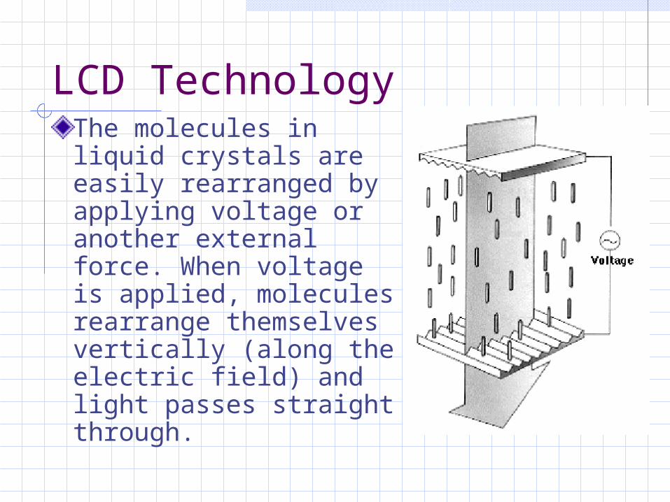
LCD TechnologyThe molecules in liquid crystals are easily rearranged by applying voltage or another external force. When voltage is applied, molecules rearrange themselves vertically (along the electric field) and light passes straight through.
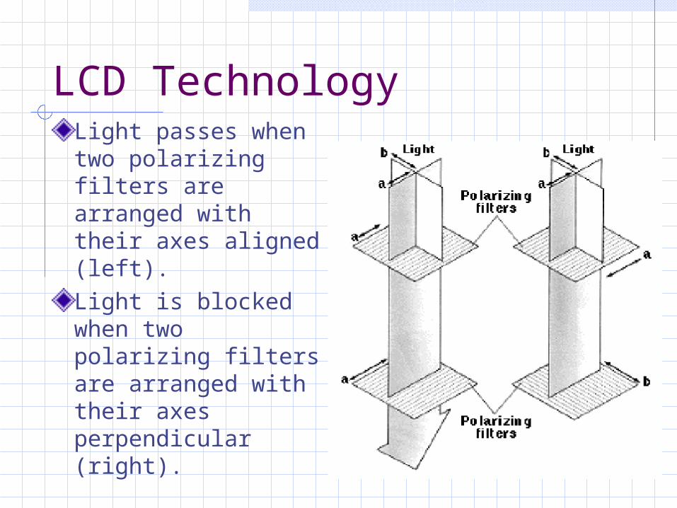
LCD TechnologyLight passes when two polarizing filters are arranged with their axes aligned (left).Light is blocked when two polarizing filters are arranged with their axes perpendicular (right).

LCD TechnologyA combination of polarizing filters and twisted liquid crystal is used to create a liquid crystal display.
LCD Character ModulesBased on Hitachi LCD-II controller protocol 1 to 4 lines, 8-20 characters per line 4 or 8 bit parallel interface Motorola style control signals 256 character font 8 user defined characters (Character
Generator RAM) Controllable cursor 2 read/write registers
Instruction/status data

LCD Character ModulesStandard Hardware Interface Contrast adjustment
Temperature considerations Control bus connections Register addressing
Bus Timing Requirements Often slower than processor – may require wait
states Sequential operations often require delay Can drive LCD module bus from I/O pins and
manipulate to get proper waveforms (bit-banging)
Backlights LED CCFL/EL

LCD CommandsCommands Display Clear Cursor Home Entry Mode Set Display On/Off Control Cursor/Display Shift Function Set Set CGRAM Address Set DDRAM Address
Using BUSY Flag
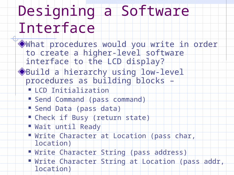
Designing a Software Interface
What procedures would you write in order to create a higher-level software interface to the LCD display?Build a hierarchy using low-level procedures as building blocks – LCD Initialization Send Command (pass command) Send Data (pass data) Check if Busy (return state) Wait until Ready Write Character at Location (pass char, location) Write Character String (pass address) Write Character String at Location (pass addr,
location)

Wrapping UpHomework #6 due Friday, May 9thth.Final exam on Saturday, May 17th from 7:45am to 9:45am in 3418 EH Cumulative exam covering Modules 1-6 More details coming soon
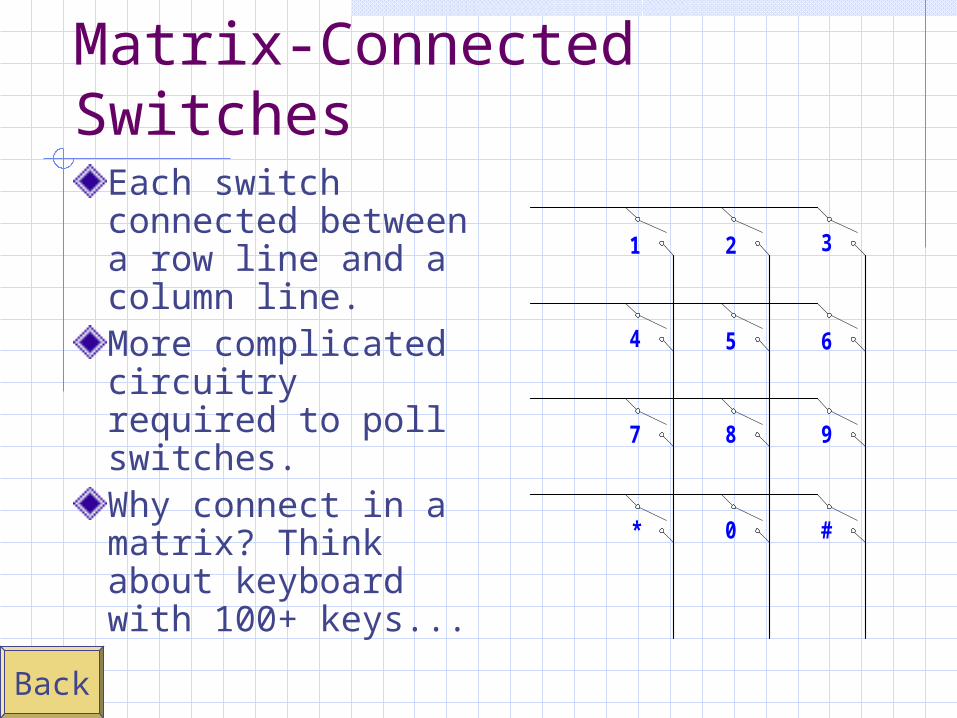
Matrix-Connected Switches
Each switch connected between a row line and a column line.More complicated circuitry required to poll switches.Why connect in a matrix? Think about keyboard with 100+ keys...
1 2 3
4 5 6
7 8 9
* 0 #
Back

KeypadExample
Back
1 2 3
4 5 6
7 8 9
* 0 #
D-FF
BUFFER
D0
D1
D2
D3
/ROW
/COL
Vdd
OE
CLK
D Q

Matrix Scanning AlgorithmAlgorithm Drive columns (or rows) low one at a time. Read the rows (or columns), any low rows (columns)
correspond to pressed switches.
Circuit Requirements Pull-up resistors to ensure that open rows (or columns)
are high. Use open-drain / open-collector driver on each column
(row) to avoid contention issues with multiple presses.
Switch Ambiguities If more than two switches are pressed, may “see”
more switches active than there really are. (phantom paths)
Can be solved by placing a series diode at each switch.Back

74C923 20-Key Encoder
Back
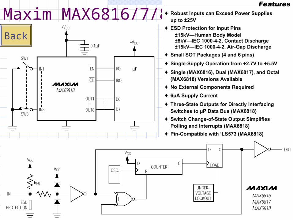
Maxim MAX6816/7/8Back

Back
Quadrature Rotary Encoders
There are normally many electrical cycles for each mechanical revolution.

Back
Rotary encoder A/B outputs typically go through many electrical cycles for a single revolution of the encoder shaft. The absolute shaft position is unknown.
An indexed rotary encoder is essentially a quadrature encoder that has an additional output that provides a single pulse during each mechanical revolution. This reference signal provides a way to
determine the absolute shaft position.
Indexed Rotary Encoders

Absolute Rotary Encoders
Back
Position(+/- 22.5°)
Output
Decimal BinaryChanged
BitsGray Code
0° 0 000 - 000
45° 1 001 1 001
90° 2 010 2 011
135° 3 011 1 010
180° 4 100 3 110
225° 5 101 1 111
270° 6 110 2 101
315° 7 111 1 100
0 ° 0 000 3 000
The n-bit output is directly proportional to the angular position.

Rotary Encoder with Interrupts
Back

Typical LED Characteristics
Back

LED Displays
Back

MAX7219Multiplexed Display Driver
Back

Back
LED current limiting resistors
MultiplexedDisplay

HW Switch DebouncingRS Latch
Back
VCC
VCC

HW Switch Debouncing
Back
RC Integrator with Schmitt-trigger gate Debounces both press and releaseV CC V CC
0V
Recommended