Fans | Air Handling Units | Air Distribution Products | Fire Safety | Air Curtains and Heating Products | Tunnel Fans
EC-fansEnergy effi cient and environmentally friendly

2
The products in this leafl et are equipped with EC-motors. EC-technology is intelligent tech-nology, using integral electronic control to ensure that the motor always runs at optimal load.
What can EC achieve?EC-fans are favoured for their economical use of energy and simplifi cation of control. EC-fans are driven by energy-saving motors with electronic control (commutation unit) ensuring optimal operating effi ciency. According to their design principle, these are synchronous motors, which run without slip and therefore no slippage losses occur. An excellent solution for demand responsive ventilation systems. Another pro-environmental aspect relevant to air supply and air conditioning equipment in particular is noise level. Here too, the advantage is with EC-motors, which run silently in controlled operating conditions. EC-motors have longer service life due to lower winding tempe ratures result-ing in lower wear and tare. EC-motors with integrated electronic control can easily be varied in speed to match airfl ow demand. For the same air volume, they consume distinctly less energy than AC motors.
EC-motors have high energy-saving potential not only at full load, but especially at part-load, where the loss of effi ciency is very much lower than with an asynchronous motor of equivalent output.
Advantages with EC motors:• Up to 90 % higher effi ciency than conventional systems• Long service life due to small heat losses in the motor• Easy to control with 0-10V DC or PWM signal• Low sound level throughout the entire fan performance• All control and protection electronics are integrated in
the motor, easy connection• Ventilation on demand – easy to adjust ventilation rate to
actual need.
The following is included when selecting an EC motor:• Overheat protection• Overload protection• Protection against locked rotor• Control electronics• Softstart, starts slowly and gradually increases to full
speed over a predefi n ed time.
Energy effi cient & environmentally friendly fans
Energy effi cient ventilation is about designing a system in a smart way, using a fan that has a high effi ciency and adjust-ing the ventilation rate to the actual need, instead of always operating at full capacity, while maintaining good indoor air quality. Today Systemair probably has the widest range of EC fans on the ventilation market, and are happy to introduce a con-trol system that will make it easy for the contractor, installer and end user to achieve Demand Control Ventilation (DCV). The system contains a central control and a room controller that are connected with SELV. (Safety Extra Low Voltage).
• Built in transformer• 24V supply to dampers• Built in humidity and temperature sensor in the room con-
troller • Ability to connect CO2 sensor, presence sensor, humidity
sensor etc. • Possibility to create a week schedule.
By using energy effi cient EC-fans with intelligent control, your system will meet the ventilation requirements of both new building and refurbishment projects.
I EC-fans
EC-Vent controlEC-Vent room unit

3
Comparison with conventional technology
Power consumption per year is based on an installation running continu-ously. The CO2 impact based on as an average of the CO2 emission to pro-duce continuously electricity for the European countries. Source: Umwelt-Bundes-Amt Germany. Factor 0.6 kg CO2/kWh
K EC/AC 200
KVKE EC/AC 315
MUB EC/AC 450E4
KBT EC/AC 200E4 TFSR EC/AC 160
EC-fans I
DVC 355-S/DVS 355E4 AC

4
• High effi ciency in all areas of the fan curve• 100 % speed controllable by 0-10V or PMW signal• Easy adjustment of ventilation rate by installed potentiometer• Electronic motor protection• Supplied with mounting bracket.
The K-EC series is designed for installation in ducts. All the K-fans have minimum 25 mm long spigot connections. The fans have backward-curved blades and external rotor motors (EC). The FK mounting clamp facilitates easy installation and removal, and prevents the transfer of vibration to the duct. The fans are delivered with a pre-wired potentiometer (0-10V), set at 10V (factory default). This can easily be adjusted should the installation require at a lower duty. To protect the motor from overheating the fan has integral thermal contacts with electrical reset. Motor protection is integrated in the electronics of the motor. The casing is manufactured from galvanised sheet steel with the seams folded to give the fan a close to air tight casing. Outdoor mounting and wet room applications are possible due to the fans air tight casing and IP 55 rated terminal box with IP 68 rated M20 cable gland.
Potentiometer 0-10V located in the electrical terminal box
K EC, circular duct fans
K EC 160 200 250 315 M 315 LVoltage/Frequency V/50 Hz 230 1~ 230 1~ 230 1~ 230 1~ 230 1~Power W 74,4 78,6 119 166 340Current A 0,63 0,63 0,92 1,14 2,08Max air fl ow m3/h 544 774 1033 1415 1732R.p.m. 3105 2468 2628 2113 2719*) Sound pressure level, 3 m dB(A) 47 51 46 50 57Weight kg 3 3,8 3,5 7 7Insulations class, motor B B B B BEnclosure class, motor IP 44 44 44 44 44
40
øA
øAøB
CD
E
(F)
88
K EC A B C D E (F)160 159 286 25 147 26 198200 199 336 30 148 27 205250 249 336 30.5 144.5 27 202315 M 314 408 32.5 160.5 27 220315 L 314 408 37.5 160.5 27 225
I EC-fans
All dimension in mm.
*) Sound pressure level at 20 m2 Sabine, equivalent to 1 m free fi eld.
FK RSK
CB LDC
FFR CWK
VBC MTP
EC-Vent
Accessories

5EC-fans I

6
KD EC, circular duct fans
KD EC øA B C øD E F G øH øI øJ K L355E 355 40 516 10(4x) 38 59 38 355 400 503 590 11400D/400E 400 44 602 12(4x) 33 61 37 400 450 560 662 18,5450D 450 46 686 12(4x) 45 76 50 450 500 660 812 18,5500D 500 46 643 12(4x) 45 76 50 450 500 660 812 18,5
• High effi ciency in all areas of the fan curve • 100% speed controllable • Integrated electronic motor protection • Supplied with mounting bracket• Easy adjustment of ventilation rate by installed potentiometer
The KD-EC series have external rotor motors (EC) with mixed fl ow im-pellers which reduce the external dimensions of the fans. The casing is manufactured from galvanised steel. These fans produce high capac-ity in relation to their compact design. Brackets are supplied with the fans to simplify installation. The FK mounting clamp facilitates easy installation and removal, and prevents the transfer of vibration to the duct. The fans are delivered with a pre-wired potentiometer(0-10V) set to 10V (factory default). This can easily be adjusted should the installation requires a lower duty. Motor protection is integrated in the electronics of the motor.
KD EC 315E 355E 400D 400E 450D 500DVoltage/Frequency V/50 Hz 230 1~ 230 1~ 400 3~ 230 1~ 400 3~ 400 3~Power W 428 355 1937 926 1872 1848Current A 1.98 1.69 2.99 4.08 2.91 2.83Max air fl ow m3/s 0.963 1.05 2.35 1.93 2.57 2.77R.p.m. 1723 1295 1906 1452 1607 1605Soundpressure level at 3 m dB(A) 71.8 53.4 73.9 62 69.3 68.1Weight kg 14,2 18.6 24 26.5 32.5 32Insulations class, motor F F F F F FEnclosure class, motor IP 54 54 54 54 54 54
KD EC 315E KD EC 355E/400D/400E/450D/500D
All dimension in mm.
FK RSK
CB LDC
FFR CWK
VBC MTP
EC-Vent
Accessories
I EC-fans
ø315
49
ø302ø315ø355ø455
484
2069
ø10(4x)
33,5
20
25
11 11
540
65 65
øAB
C
øD
EF GøH
øIøJ
K
L L

7
KD-EC 315E KD-EC 355E
10V
2,8V
KD-EC 400E
92
9183
82
73
73
5858
10V
5,3V
KD-EC 450D
10V
3,5V
KD-EC 500D
EC-fans I

8
• High effi ciency in all areas of the fan curve• 100% speed controllable• Integrated electronic motor protection• Easy adjustment of ventilation rate by installed potentiometer• Low noise level
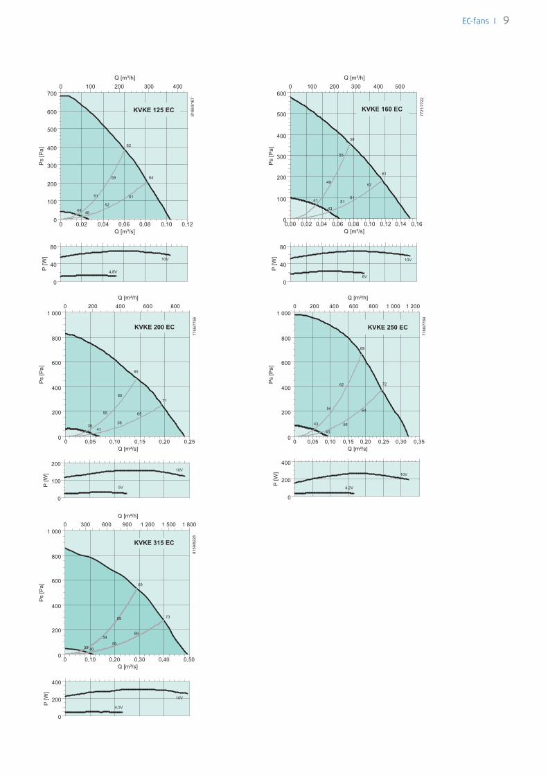
The KVKE EC models have impellers with backward-curved blades and maintenance-free external rotor motor (EC). These fans develop rela-tively high static pressure and produce very high effi ciency. The fans are delivered with a pre-wired potentiometer (0-10V). The potenti-ometer is pre-set to 10V (factory default). This can be adjusted should the installation require a lower duty. The KVKE motor and impeller are mounted on the access cover for easy maintenance. The service cover can be easily removed by with-drawing the hinge pin. Motor protection is integrated in the electronics of the motor. The fans can be installed in any position and are easy to connect to spiral ducts using FK mounting clamps. The KVKE casings are manufactured from galvanised sheet steel and are thermally and acoustically insulated with a 50 mm layer of rockwool with a surface liner which prevents the migration of fi bres into the airstream. The plug and socket contact between lid and casing ensures that when opening the fan casing the fan is separated from the mains supply. No need for on/off switches for maintenance.
Potentiometer 0-10V located in the lid
KVKE EC, circular duct fans
* ) Handle on KVKE 315 EC
I EC-fans
KVKE EC A B C D E F G H
125 125 433 479 125 128.5 442 246 470
160 160 482 528 145.5 132.5 505 266 530
200 200 482 534 150.5 149 505 303 530
250 250 578 700 176 174 596 359 620
315 315 680 802 208.5 207.5 705.5 430 730
KVKE EC 125 160 200 250 315Voltage/Frequency V/50 Hz 230~ 230~ 230~ 230~ 230~Power W 68.7 67.8 156 265 395Current A 0,54 0,53 1,10 1,64 2,38Max air fl ow m3/h 374 544 864 1156 1865R.p.m. 3339 2592 3033 2821 2380*)Sound pressure level, 3 m dB(A) 41 39 46 49 50Weight kg 13 17,5 19 28,1 38,8Insulation class, motor B B B B BEnclosure class, motor IP 44 44 44 44 44
D
E
GH
50
F
27
C B
47
A
*)
*) Sound pressure level at 20 m2 Sabine (equivalent to 1 m free fi eld)
315315
FK RSK
CB LDC
FFR CWK
VBC MTP
EC-Vent
Accessories
9EC-fans I

10 I EC-fans
• High effi ciency in all areas of the fan curve• 100% speed controllable• Integrated electronic motor protection• Easy adjustment of ventilation rate by installed potentiometer• Low noise level
The KVO-EC motor and impeller are mounted on the access cover for ease of maintenance. The service cover can be easily removed by withdrawing the hinge pin. Motor protection is integrated in the electronics of the motor. The fans can be installed in any position and are easy to connect to spiral ducts using FK mounting clamps. The KVO-EC models are manufactured from galvanised sheet steel and the lid is insulated with 40mm rockwool. The fans are delivered with a pre-wired potentiometer (0-10V) that allows you to easily select the desired working point.
KVO EC, insulated circular duct fans
A
FD
HG
EC B
KVO A B C D E F G H100 100 329 367 69 76 300 150 150125 125 329 367 84 72 300 150 150160 160 329 367 99 90 300 185 185200 200 419 466 123 109 435 220 220250 250 527.5 568 151 133 558 270 270315 315 535.5 580 186 166 580 340 550355 355 572 661 209 231 640 425 600400 400 572 653 221 209 640 425 600
KVO EC 100 125 160 200 250 315Voltage/Frequency V/50 Hz 230 1~ 230 1~ 230 1~ 230 1~ 230 1~ 400 3~Power W 60 111 116 123 312 331Current A 0.48 0.86 0.89 0.96 1.91 2.04Max air fl ow m3/s 0.09 0.13 0.15 0.24 0.47 0.53R.p.m. 2499 2724 2411 2577 2799 2264Sound pressure level at 3 m dB(A) 43.2 47.6 48.4 50.7 57.4 55.4Weight kg 5.6 5.6 6 10.3 20.4 25.6Insulation class, motor B B F B F FEnclosure class, motor IP 44 44 44 44 44 44

11
0 0.03 0.06 0.090
100
200
300
400
[m³/s]
[Pa]
0 100 200 300[m³/h]
1132
7/11
328
43 47
56
57
56
58
62
64
0 0.03 0.06 0.090
100
[m³/s]
[W]
KVO-EC 100
0 0.04 0.08 0.12 0.160
100
200
300
400
500
[m³/s]
[Pa]
0 200 400[m³/h]
1134
0/11
341
48 55
53
54
63
64
65
66
69
70
KVO-EC 125
0 0.04 0.08 0.12 0.160
30
60
90
120
[m³/s]
[W
10V
4,5V]
0 0.04 0.08 0.12 0.160
200
400
600
800
[m³/s]
[Pa]
0 200 400[m³/h]
1131
7/11
318
49 48
5456
63
65
72
72
KVO-EC 160
0
30
60
90
120
[W]
0 0.1 0.2 0.30
200
400
600
800
[Pa]
0 300 600 900[m³/h]
1132
3/11
324
47 47
5861
65
69
72
75
0
40
80
120
160
[W]
KVO-EC 200
[m³/s]
0 0.2 0.4 0.60
250
500
750
1000
[m³/s]
[Pa]
0 400 800 1200 1600 2000[m³/h]
1133
8/11
339
5350
62
63
71
73
79
79
KVO-EC 250
0
100
200
300
400
[W]
0 0.2 0.4 0.60
250
500
750
1000
[m³/s]
[Pa]
0 500 1000 1500 2000[m³/h]
1134
9/11
351
5255
66
70
76
79
81
83
0
100
200
300
400
[W]
KVO-EC 315
EC-fans I

12
• High effi ciency in all areas of the fan curve• 100 % speed controllable• Integrated electronic motor protection• Low noise level• Flexible air fl ow direction due to removable panels • Installation in any mounting position• Safe and maintenance free operation
MUB-EC fans are driven by EC-external rotor motors. All motors are suitable for 50/60Hz. The input voltage for single phase units can vary between 200 and 277V, for three phase units between 380 and 480V. Speed control by a 0-10V signal (MTP/MTV controller or EC-Vent). All models are equipped with impellers with backward curved blades, manufactured from aluminium. The casing consists of an aluminium frame with fi breglass reinforced plastic corners of PA6; and are shock-resistant. The double skin panels are manufactured from galvanized steel with 20 mm mineral wool insulation. The panels are removable, any outlet side can be used, allowing fl exible ventilation solutions.Installation in any mounting position is possible.
The Mini-MUB model has an insulated casing (20 mm Armafl ex), manu-factured from galvanised steel, and PA6 25GV impellers.
MUB EC, square duct fans
I EC-fans
MUB EC 025 315 A2 025 355 A2 042 400 A2 042 450 A2-K 042 450 A2 042 500 A2 062 560 A2 062 630 A2Voltage/Frequency V/50 Hz 230~ 230~ 230~ 400 3~ 230~ 400 3~ 400 3~ 400 3~
Power W 180 430 378 1170 580 1100 2000 2560Current A 1,40 2,70 2,26 1,95 2,40 2,18 3,10 3,90Max air fl ow m3/h 2466 3000 3881 6300 5100 7440 10789 13050R.p.m. 1870 1660 1339 1560 1250 1340 1360 1210*) Sound pressure level, 3 m dB(A) 44 48 48 56 52 56 57 67Weight kg 30 37 58 62 62 70 135 130Insulation class, motor B B B B B B F FEnclosure class, motor IP 44 44 44 54 54 54 54 54
øE
øD
�C
�F
�B
�A
MUB EC A B C øD øE F
025 315 500 500 420 315 200 40
025 355 500 500 420 355 224 40
042 400 670 670 590 400 253 40
042 450 670 670 590 454 286 70
042 450 K 670 670 590 450 286 70
042 500 670 670 590 504 321 70
062 560 800 800 720 560 360 70
062 630 800 800 720 630 407 70
Coming soon: MUB-EC with integrated potentiometer for easy
adjustment of the ventilation rate.
*) Sound pressure level at 20 m2 Sabine (equivalent to 1 m free fi eld)
Mini MUB 200

13
Straight through air direction
•••••• 90° air direction
EC-fans I

14
• High effi ciency in all areas of the fan curve• 100 % speed controllable• Integrated electronic motor protection• Low noise level• Safe and maintenance free operation
The DVC roof fans are driven by EC-external rotor motors, energy saving motors with high effi ciency. The input voltage for single phase units can vary between 200 and 277V, for three phase units between 380 and 480V. All motors are compatible with 50 and 60Hz supply. Motor protection is integrated in the electronics of the motor, no additional external motor protection device is required. Casing from seawater-resistant aluminum. Backward curved impellers manufac-tured from polyamide PA 6 for size 190 and 315. From 355 up to 630 impellers manufactured from seawater resistant aluminium. DVC-S suitable for speed control with potentiometer. DVC-P with integrated pressure sensor, the electronics in the motor are programmed for a contstant pressure operation.
DVC/DVCI, roof fans
I EC-fans
�A
�B
C
øD
�E
�F
G M20x1,5
G
øI(4x)
H
øD
DVC/DVCI A B C øD E190-225 370/497 295 170/179 213 335315 560/690 470 330 285 435355-400 720/874 618 390/439 438 595450-500 900/968 730/748 465/479 438 665560-630 (DVC) 1150/1315 955/1035 560/600 605 939
F G H øI245 105 6xM6 10(4x)330 146 6xM6 10(4x)450 200 6xM8 12(4x)535 237 6xM8 12(4x)750 293 8XM8 14(4x)
DVC/DVCI 225-P/225-S 315-P/315-S 355-P/355-S 400-P/400-S 450-PK/450-SK
Voltage/Frequency V/50/60 Hz 230 1~ 230 1~ 230 1~ 230 1~ 230 1~
Power (P1) W 166 173 378 381 614
Current A 1.17 1.18 2.31 2.30 2.79
Max air fl ow m3/s 0.261 0.546 0.918 1.00 1.43
R.p.m. min-1 3278 1867 1657 1348 1300
Max temp. of transported air °C 60 60 60 60 60
“ when speed controlled °C 60 60 60 60 60
Sound pressure level, 4 m/10 m, DVC dB(A) 58/51 47/39 50/42 49/41 53/45
Sound pressure level, 4 m/10 m, DVCI dB(A) 53/45 41/33 46/38 43/35 40/32
Weight, DVC/DVCI kg 8/13 11/16 25/30 29/34 45/38
Insulation class, motor B B B B B
Enclosure class, motor IP 44 44 44 44 54
DVC/DVCI 450-P/450-S 500-P/500-S 560-P/560-S 630-P/630-S
Voltage/Frequency V/50/60 Hz 400 3~ 400 3~ 400 3~ 400 3~
Power W 1048 984 1873 2444
Current A 1.79 1.66 2.88 3.72
Max air fl ow m3/s 1.70 1.84 2.99 3.59
R.p.m. min-1 1558 1339 1359 1209
Max temp. of transported air °C 60 60 60 60
“ when speed controlled °C 60 60 60 60
Sound pressure level, 4 m/10 m, DVC dB(A) 51/48 55/47 63/55 64/56
Sound pressure level, 4 m/10 m, DVCI dB(A) 50/42 51/43 55/47 57/49
Weight, DVC/DVCI kg 45/43 49/57 DVC 60/60 DVCI 70/70 DVC 80/80 DVCI 90/90
Insulation class, motor B B F F
Enclosure class, motor IP 54 54 54 54
Coming soon: DVC-S with integrated potentiom-eter for easy adjustment of ventilation rate.

15EC-fans I

16 I EC-fans
• Integrated pressure sensor, no power supply required• Temperature sensor for outdoor temperature compensation• 100 % speed controllable• Integrated motor protection• Safe and maintenance free operation• Sizes 315 up to 500 include a tilting device for service options The DVC-POC roof fans are driven by EC- external rotor motors, energy saving motors with high effi ciency. The input voltage for single phase units can vary between 200 and 277V, for three phase units between 380 and 480V. All motors are compatible with 50 and 60Hz supply and from size 355 up to 630 are suspended on effective vibration mountings. Motor protection is integrated in the electronics of the motor, no additional external motor protection device is needed. The DVC-POC versions have integrated pressure sensors and tem-perature sensor for outdoor temperature compensation. The electron-ics can be programmed for pressure constant operation or pressure constant operation combined with outdoor temperature compensa-tion. The factory setting is pressure constant operation with outdoor temperature compensation. Casing from seawater-resistant aluminum. Backward curved impel-lers manufactured from polyamide PA 6 for size 315. From 355 up to 630 impellers manufactured from seawater resistant aluminium.
DVC POC + FTG, roof fan
DVC POC+FTG 315 355 400 450-K 450 500DVC POC 560 630Voltage/Frequency V/50/60 Hz 230 1~ 230 1~ 230 1~ 230 1~ 400 3~ 400 3~ 400 3~ 400 3~
Power W 173 378 381 580 1048 984 1873 2444Current A 1,18 2,31 2,3 2,79 1,79 1,66 2,88 3,72Max air fl ow m3/s 0,546 0,918 1 1,83 1,7 1,84 2,99 3,59R.p.m. 1867 1657 1348 1250 1558 1339 1359 1209Max temp. of transported air °C 60 60 60 60 60 60 60 60“when speed controlled °C 60 60 60 60 60 60 60 60Sound pressure level, 4 m dB(A) 47 52 49 53 56 55 63 64Sound pressure level, 10 m dB(A) 39 42 41 45 48 47 55 56Weight kg 25 25 29 45 45 49 58 85Insulation class, motor B B B B B B B FEnclosure class, motor IP 44 44 44 54 44 54 54 54
H
M20x1,5
I
K
G_
G__
F
B
A
CDL
E
DVC POC A B C D E F G H øI øK L315 560 470 330 393 435 330 146 6xM6 10(4x) 285 443355 720 618 390 454 595 450 200 6xM6 12(4x) 438 504400 720 618 390 475 595 450 200 6xM8 12(4x) 438 525450K/450/500 900 730 465 530 665 535 237 6xM8 12(4x) 438 580560/630 1150 955 560 600 939 750 293 8xM8 14(4x) 605 -

17
0 0.2 0.4 0.60
100
200
300
400
500
[m³/s]
[Pa]
0 500 1000 1500 2000[m³/h]
5835
/583
6
050
100150200
[W]
DVC 315-POC + FTG
5657
65
65
71
72
75
76
0 0.4 0.8 1.20
200
400
600
[m³/s]
[Pa]
0 2000 4000[m³/h]
5828
/582
9
0100200300400
[W]
DVC 355-POC + FTG
50 44
60
62
69
74
73
79
80
82
0 0.4 0.8 1.20
200
400
600
[m³/s]
[Pa]
0 2000 4000[m³/h]
5837
/583
8
0100200300400
[W]
DVC 400-POC + FTG
44 44
61
65
70
76
76
79
0 0.5 1 1.50
100
200
300
400
500
600
[m³/s]
[Pa]
0 2000 4000[m³/h]
7231
0
250
500
750
[W]
DVC 450-K-POC + FTG
0 0.5 1 1.5 20
200
400
600
800
[m³/s]
[Pa]
0 2500 5000[m³/h]
5966
/596
7
0
400
800
1200
[W]
DVC 450-POC + FTG
50 53
65
70
75
82
82
8687
83
0 0.5 1 1.5 20
200
400
600
800
[m³/s]
[Pa]
0 2500 5000[m³/h]
5969
/597
0
0
400
800
1200
[W]
DVC 500-POC + FTG
47 46
7162
74
78
78
80
86
87
0 1 2 30
200
400
600
800
[m³/s]
[Pa]
0 4000 8000[m³/h]
5977
/597
8
0500
100015002000
[W]
DVC 560-POC
50 51
65
70
73
77
85
92
88
92
0 2 40
200
400
600
800
[m³/s]
[Pa]
0 5000 10000[m³/h]
5974
/597
5
0
1000
2000
3000
[W]
DVC 630-POC
57 54
74
76
85
90
93
98
92
96
EC-fans I

18 I EC-fans
DVG EC, roof fan
DVG EC H-355/F400
H-450/F400
H-560/F400
H-630/ F400
H-800/F400
V-355/F400
V-450/F400
V-560/F400
V-630/F400
V-800/F400
Voltage V 230 1~ 230 1~ 400 3~ 400 3~ 400 3~ 230 1~ 230 1~ 400 3~ 400 3~ 400 3~
Power W 400 925 2420 5065 4865 400 925 2490 5055 4790Current A 1,8 4 3,7 8 7,7 1,8 4 3,8 8 7,7Max air fl ow m3/s 0,904 1,724 3,642 5,338 7,673 0,862 1,612 3,419 5,059 6,978R.p.m. [min -1] 1500 1450 1400 1455 930 1500 1450 1400 1465 930Sound power level, 4/10 m dB(A) 59/63 67/60 75/69 78/72 81/72 56/50 65/58 72/67 75/69 74/66Weight kg 41 53 101 110 192 43 57 106 115 199Insulation class, motor F F F F F F F F F FEnclosure class, motor IP 54 54 54 54 54 54 54 54 54 54
�B
(n x M)ødf
A
øE
H
�A
H1
F
Max 240
A
H
G
B
øE
ødf (nxM)
Max 240
H1A
DVG A øB E F G ødf (nxM) H1 H
355 598 450 12 1003 704 438 (6xM8) 30 567
450 668 535 12 1261 854 438 (6xM8) 30 637
560 943 750 14 1540 1078 605 (8xM8) 30 773
630 1039 840 14 1573 1072 674 (8xM8) 40 858
800 1255 1050 14 2024 1280 872 (8xM8) 40 999
DVG-H
DVG-V
• Up to 400°C/120 min (F400/120, F400/90, F300, F200)• Normal ventilation up to 120°C continuous operation• Horizontal (DVG-H) exhaust or vertical exhaust (DVG-V)
DVG smoke extract fans are used in case of fi re to extract smoke gases from rooms, and also during normal working conditions for standard ventilation. Smoke-free escape ways increase the chances to rescue people in case of fi re. The casing is manufactured from seawater resistant aluminium. The base frame consists of galvanised steel. The impeller with backward-curved blades is manufactured from galvanised steel. Motor outside air stream. In the case of fi re switch to fi re mode where the bridging of motor protection devices is necessary.

19
0 0.25 0.5 0.75 10
100
200
300
400
500
[m³/s]
[Pa]
0 1000 2000 3000[m³/h]
DVG-H 355EC/F400
0 0.5 1 1.5 20
200
400
600
800
[m³/s]
[Pa]
0 2000 4000 6000[m³/h]
DVG-H 450EC/F400
0 1 2 3 40
250
500
750
1000
[m³/s]
[Pa]
0 4000 8000 12000[m³/h]
DVG-H 560EC/F400
0 2 4 60
300
600
900
1200
[m³/s]
[Pa]
0 5000 10000 15000 20000[m³/h]
DVG-H 630EC/F400
0 2 4 6 80
250
500
750
1000
[m³/s]
[Pa]
0 5000 10000 15000 20000 25000[m³/h]
DVG-H 800EC/F400
0 0.25 0.5 0.75 10
100
200
300
400
500
[m³/s]
[Pa]
0 1000 2000 3000[m³/h]
DVG-V 355EC/F400
0 2 4 6 80
250
500
750
1000
[m³/s]
[Pa]
0 5000 10000 15000 20000 25000[m³/h]
DVG-V 800EC/F400
0 0.5 1 1.5 20
200
400
600
800
[m³/s]
[Pa]
0 2000 4000 6000[m³/h]
DVG-V 450EC/F400
0 1 2 3 40
250
500
750
1000
[m³/s]
[Pa]
0 4000 8000 12000[m³/h]
DVG-V 560EC/F400
0 2 4 60
300
600
900
1200
[m³/s]
[Pa]
0 5000 10000 15000 20000[m³/h]
DVG-V 630EC/F400
EC-fans I

20
TFSR/TFSK EC, roof fan• High effi ciency EC-motors • 100 % speed controllable • Potentiometer included• Swing-out
The TFSR-EC and TFSK-EC roof mounted fans are driven by EC motors and intended for use as extract fans in smaller premises such as self contained fl ats and apartments as well as storage areas, small work-rooms etc. EC-technology is intelligent technology, using integral elec-tronic control to ensure that the motor always runs at optimal load. The fans are delivered with a pre-wired potentiometer(0-10V) that allows you to easily select the desired working point. The isolation switch is integrated and there are several alternative roof curbs avail-able as accessories. The tilting mechanism simplifi es cleaning and main-tenance. Includes electronic motor protection. The horizontal discharge creates smaller internal pressure losses and prevents accumulation of ice on the roof. The protection guard prevents unintentional contact with the impeller.
I EC-fans
TFSR TFSK
HC = Hole diameter for fi xing, ø6x4
øC
HCøD
A B
øC
c/c Fø9(4x)
�E
A B36
TFSR EC A B C D HC160 147 172 334 380 205200 150 187 364 439 250
TFSK EC A B øC E c/cF160 147 172 334 421 330200 150 187 364 421 330
TFSR/TFSK EC 160 200
Voltage/Frequency V/50/60 Hz 230 1~ 230 1~
Power W 81.5 74.6
Current A 0.64 0.587
Max. air fl ow m3/s 0.161 0.216
R.p.m. min-1 3162 2501
Max temp. of transported air °C 45 45
“ when speed controlled °C 45 45
Sound pressure level, 3m dB(A) 43 43
Weight kg 4.2/4.6 5.4/6.2
Insulation class, motor B B
Enclosure class, motor IP 44 IP 44

21EC-fans I

22
KBR/KBT EC, thermo box• 100 % speed controllable • Integrated motor protection • Low noise level• Max temperature of transported air 120°C.
KBR-EC fans have impellers manufactured from galvanized sheet steel with backward-curved blades. KBT-EC fans have impellers manufac-tured from galvanized sheet steel with forward-curved blades. The casing for KBR/KBT-EC are manufactured from double skinned galva-nized steel and are insulated with 50 mm mineral wool. KBR/KBT-EC have a swing-out door for easy inspection and servicing. The direction of the door opening can be easily changed from left to right on site. The fan is resiliently mounted with anti vibration mountings which are incorporated in the base frame.
I EC-fans
A
D
E
CB
HM
ØG
F
L
50 50Ø
G
K
J
38
KBT EC A B C D E F øG H J K L M200 142.7 445 249 292 510 130 200 174 232 78 450 35250 160 500 285 333 576 130 250 213 272 78 600 35
DE
33C
B
5050L
J
G
A
130
78
38
H35
G
KBR EC A B C D E øG H J L280 171.5 537 295 360 625 280 234 291 600315 187.5 600 339 398 690 315 249 307 800355 206.7 655 372 451 770 355 273 331 770
KBR EC 280 315 315-L 355 355-K 355-L
KBT EC 200 250
Voltage/Frequency V/50/60 Hz 230 1~ 230 1~ 230 1~ 230 1~ 230 1~ 400 3~ 230 1~ 400 3~
Fan power consumption (P1) W 107 173 1268 498 296 2567 535 1252
Current A 0.502 0.771 5.53 2.17 1.3 3.92 2.43 2.01
Max air fl ow m3/s 0.426 0.579 1.12 0.997 0.822 1.86 0.554 0.925
R.p.m. min-1 1512 1512 3025 1495 1514 2610 1498 1370
Max temp. of transported air °C 120 120 120 120 120 120 70 120
“ when speed controlled °C 120 120 120 120 120 120 70 120
Sound power level, 4/10 m dB(A) 31/23 34/26 49/41 39/31 39/31 52/44 36/28 37/29
Weight kg 47 75 75 81 81 83 35.6 52.5
Insulation class, motor F F F F F F F F
Enclosure class, motor IP 55 IP 55 IP 55 IP 55 IP 55 IP 55 IP 55 IP 55

23
KBR 280EC KBR 315EC KBR 315EC-L
KBR 355EC KBR 355EC-K KBR 355EC-L
KBT 200ECKBT 250EC
EC-fans I

Syst
emai
r AB
• May
201
2 • A
rt n
o E8
076
www.systemair.com
Recommended