DESIGN AND RATING
SHELL AND TUBE
HEAT EXCHANGERS
By John E. Edwards
Design and Rating of Shell and Tube Heat Exchangers
PAGE 2 OF 30 MNL 032A Issued 29 August 08, Prepared by J.E.Edwards of P & I Design Ltd, Teesside, UK www.pidesign.co.uk
Contents
1.0 Introduction 2.0 Fundamentals 2.1 Basic Theory 2.2 Heat Transfer Model Selection 3.0 Design Guidelines
Appendices
I Thermal Design Models Synopsis II CC-THERM User Guidelines III Thermal Model Selection IV Shortcut Heat Exchanger Design V TEMA Heat Exchanger Layout Designation VI Typical Overall Heat Transfer Coefficients VII Typical Resistance Fouling Coefficients VIII LMTD Correction Factor Ft IX Wolverine Tube General Details X Midland Wire Cordage Turbulator Details XI Tube Dimensional Data XII Shell Tube Count Data
References
1. Hewitt,G.F. et al (1994) Process Heat Transfer, (CRC Press) 2. Perry,R.H. and Green, D. (1984) Perry’s Chemical Engineers Handbook, 6th edition (McGraw Hill) 3. Kern,D.Q. (1950) Process Heat Transfer (McGraw Hill) 4. Coulson,J.M. and Richardson,J.F. (1993) Chemical Engineering Vol 1, 4th edition (Pergamon) 5. Skinnet,R.K. (1993) Coulson & Richardson’s Chemical Engineering Vol 6, 2nd edition (Pergamon) 6. Chemstations,Inc. CHEMCAD THERM Version 5.1 User Guide 7. Schlunder,E.U. (1993) VDI Heat Atlas (Woodhead Publishing) 8. Seider,D.S., Seader,J.D.Seader and Lewin,R.L. Process Design Principles, (John Wiley & Sons, Inc.) [ C20] References of this type are to be found in CC-THERM > Help > Appendix
Design and Rating of Shell and Tube Heat Exchangers
PAGE 3 OF 30 MNL 032A Issued 29 August 08, Prepared by J.E.Edwards of P & I Design Ltd, Teesside, UK www.pidesign.co.uk
1. 0 Introduction
Shell and tube heat exchangers are used extensively throughout the process industry and as such a basic understanding of their design, construction and performance is important to the practising engineer. The objective of this paper is to provide a concise review of the key issues involved in their thermal design without having to refer to the extensive literature available on this topic. The author claims no originality but hopes that the format and contents will provide a comprehensive introduction to the subject and enable the reader to achieve rapid and meaningful results. The optimum thermal design of a shell and tube heat exchanger involves the consideration of many interacting design parameters which can be summarised as follows:
Process
1. Process fluid assignments to shell side or tube side. 2. Selection of stream temperature specifications. 3. Setting shell side and tube side pressure drop design limits. 4. Setting shell side and tube side velocity limits. 5. Selection of heat transfer models and fouling coefficients for shell side and tube side.
Mechanical
1. Selection of heat exchanger TEMA layout and number of passes. 2. Specification of tube parameters - size, layout, pitch and material. 3. Setting upper and lower design limits on tube length. 4. Specification of shell side parameters – materials, baffle cut, baffle spacing and clearances. 5. Setting upper and lower design limits on shell diameter, baffle cut and baffle spacing.
There are several software design and rating packages available, including AspenBJAC, HTFS and CC-THERM, which enable the designer to study the effects of the many interacting design parameters and achieve an optimum thermal design. These packages are supported by extensive component physical property databases and thermodynamic models. It must be stressed that software convergence and optimisation routines will not necessarily achieve a practical and economic design without the designer forcing parameters in an intuitive way. It is recommended that the design be checked by running the model in the rating mode. It is the intention of this paper to provide the basic information and fundamentals in a concise format to achieve this objective. The paper is structured on Chemstations CC-THERM software which enables design and rating to be carried out within a total process model using CHEMCAD steady state modelling software. However the principles involved are applicable to any software design process.
In the Attachments a Design Aid is presented which includes key information for data entry and a shortcut calculation method in Excel to allow an independent check to be made on the results from software calculations. Detailed mechanical design and construction involving tube sheet layouts, thicknesses, clearances, tube supports and thermal expansion are not considered but the thermal design must be consistent with the practical requirements. Source references are not indicated in the main text as this paper should be considered as a general guidance note for common applications and is not intended to cover specialist or critical applications. Sources for this paper have been acknowledged where possible. The symbols, where appropriate, are defined in the main text. The equations presented require the use of a consistent set of units unless stated otherwise.
Design and Rating of Shell and Tube Heat Exchangers
PAGE 4 OF 30 MNL 032A Issued 29 August 08, Prepared by J.E.Edwards of P & I Design Ltd, Teesside, UK www.pidesign.co.uk
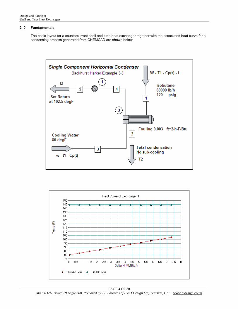
2. 0 Fundamentals
The basic layout for a countercurrent shell and tube heat exchanger together with the associated heat curve for a condensing process generated from CHEMCAD are shown below:
Design and Rating of Shell and Tube Heat Exchangers
PAGE 5 OF 30 MNL 032A Issued 29 August 08, Prepared by J.E.Edwards of P & I Design Ltd, Teesside, UK www.pidesign.co.uk
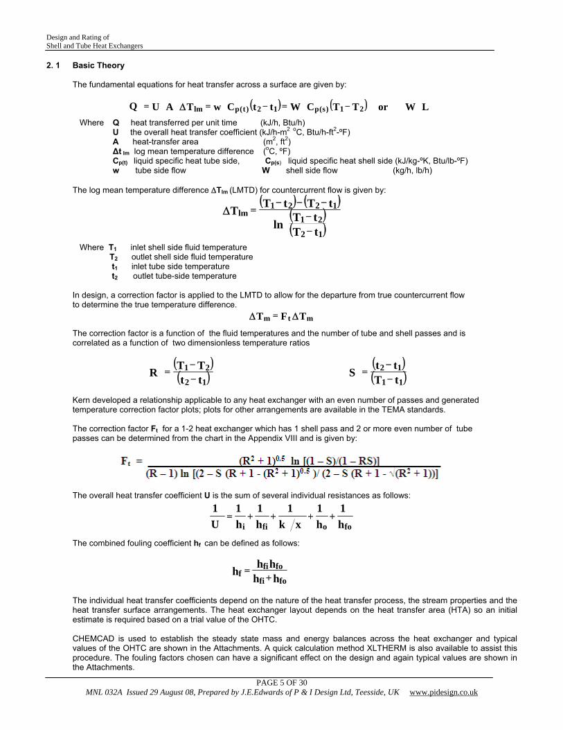
2. 1 Basic Theory The fundamental equations for heat transfer across a surface are given by:
Where Q heat transferred per unit time (kJ/h, Btu/h) U the overall heat transfer coefficient (kJ/h-m2 oC, Btu/h-ft2-ºF) A heat-transfer area (m2, ft2) Δt lm log mean temperature difference (oC, ºF) Cp(t) liquid specific heat tube side, Cp(s) liquid specific heat shell side (kJ/kg-ºK, Btu/lb-ºF) w tube side flow W shell side flow (kg/h, lb/h) The log mean temperature difference ΔTlm (LMTD) for countercurrent flow is given by:
Where T1 inlet shell side fluid temperature T2 outlet shell side fluid temperature t1 inlet tube side temperature t2 outlet tube-side temperature
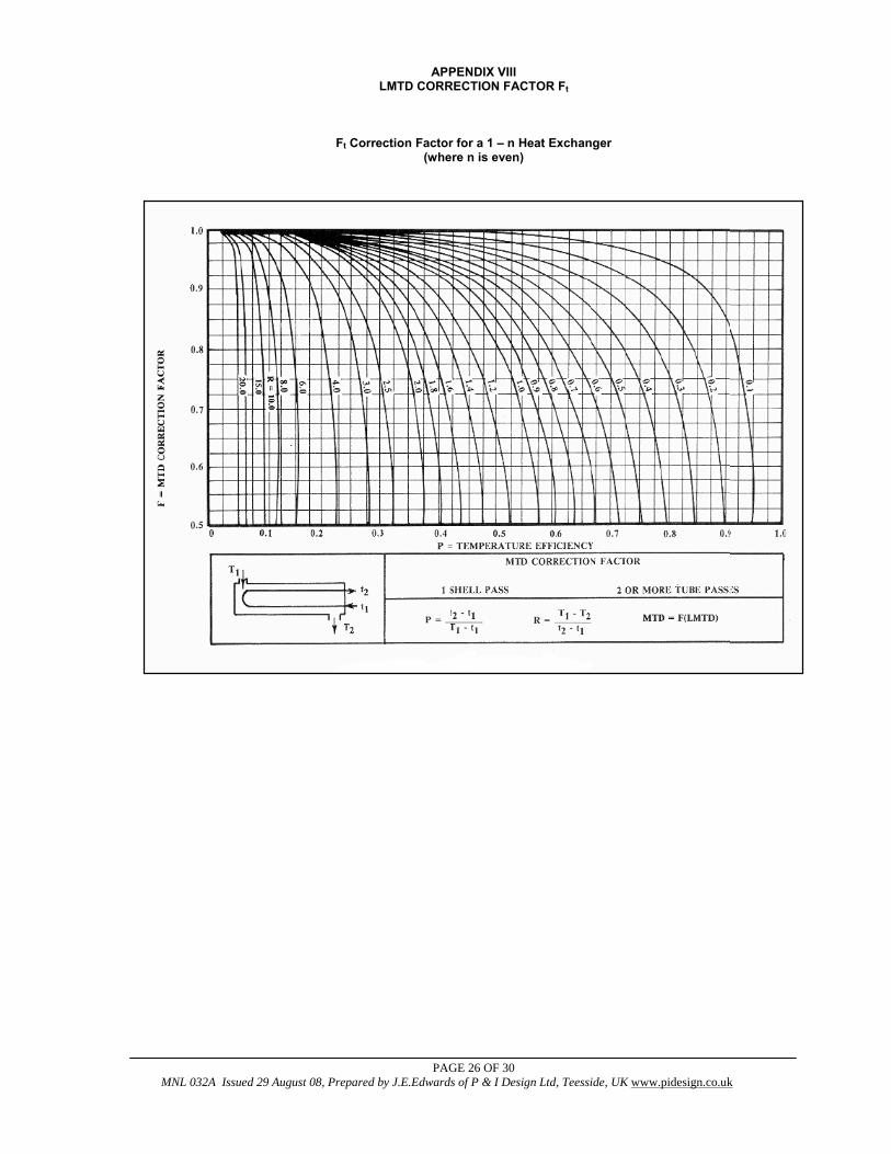
In design, a correction factor is applied to the LMTD to allow for the departure from true countercurrent flow to determine the true temperature difference. The correction factor is a function of the fluid temperatures and the number of tube and shell passes and is correlated as a function of two dimensionless temperature ratios
Kern developed a relationship applicable to any heat exchanger with an even number of passes and generated temperature correction factor plots; plots for other arrangements are available in the TEMA standards. The correction factor Ft for a 1-2 heat exchanger which has 1 shell pass and 2 or more even number of tube passes can be determined from the chart in the Appendix VIII and is given by:
The overall heat transfer coefficient U is the sum of several individual resistances as follows:
The combined fouling coefficient hf can be defined as follows: The individual heat transfer coefficients depend on the nature of the heat transfer process, the stream properties and the heat transfer surface arrangements. The heat exchanger layout depends on the heat transfer area (HTA) so an initial estimate is required based on a trial value of the OHTC. CHEMCAD is used to establish the steady state mass and energy balances across the heat exchanger and typical values of the OHTC are shown in the Attachments. A quick calculation method XLTHERM is also available to assist this procedure. The fouling factors chosen can have a significant effect on the design and again typical values are shown in the Attachments.
hhhhh
fofi
fofif +=
( ) ( ) LWorTTCWttCwTAUQ 21)s(p12)t(plm −=−== Δ
( ) ( )( )( )tT
tTln
tTtTT
12
211221
lm
−−
−−−=Δ
TFT mtm ΔΔ =
( )( )tt
TTR12
21−−
=( )( )tT
ttS11
12−
−=
h1
h1
xk1
h1
h1
U1
foofii++++=
Design and Rating of Shell and Tube Heat Exchangers
PAGE 6 OF 30 MNL 032A Issued 29 August 08, Prepared by J.E.Edwards of P & I Design Ltd, Teesside, UK www.pidesign.co.uk
2.2 Heat Transfer Model Selection
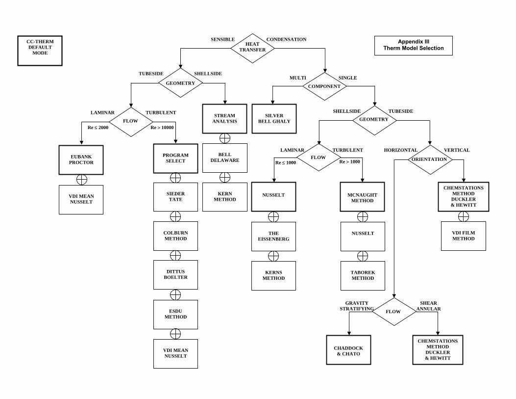
The heat transfer model selection is determined by the heat transfer process (sensible, condensing, boiling), the surface geometry (tube-side, shell-side), the flow regime (laminar, turbulent, stratifying, annular), and the surface orientation (vertical, horizontal). A heat transfer model selection flow chart is presented in the Appendix IV to assist in this procedure. This flow chart indicates all the models available in CC-THERM and shows the default selections. A synopsis of the various heat transfer models together with their conditions of application is given in Appendix I. The key features of the models are summarised below: Shellside Film Coefficient Methods for Single Component Condensation in Laminar Flow
The Nusselt Method is used for horizontal condensation under stratifying conditions where the liquid film is draining under gravity with minimum influence due to vapour shear. This is the CC-THERM default method. The Eissenberg Method is applicable to condensation over tube banks and considers condensate layer thickening behaviour. This provides the most conservative heat transfer coefficient prediction as compared to the Nusselt and Kern methods for condensation over a single tube. Range of application is for Reynolds Numbers to be in the range 1800 to 2000. The Kern Method Kern adapted the Nusselt equation to allow evaluation of fluid conditions at the film temperature. This method requires the film to be in streamline flow with a Reynolds Numbers range 1800 to 2100. Shellside Film Coefficient Methods for Single Component Condensation in Turbulent Flow
The Colburn Method is based on a correlation of industrial data for a wide range of fluids in heat exchangers using standard tube pitch designs. Range of application is for Reynolds Numbers to be in the range 2000 to E06 gives results with a deviation +20% safe. It provides a good method for the verification of computer derived heat transfer coefficients. The McNaught Method takes into account the effects of shear controlled heat transfer and the combination of gravity and shear effects. This is the CC-THERM default method. Tubeside Film Coefficient Methods for Single Component Condensation The Chaddock and Chato adaptation of the Nusselt Method The method is applicable for gravity controlled condensation where the influence of vapour shear is low and we have a liquid film draining under gravity forming a stratified layer at the bottom of the tube The Chemstations Method This is based on Duckler (downflow) and Hewitt (upflow) adaptations to Deissler and von Karman equations. The method is applicable to condensation under shear controlled conditions for vertical and horizontal layouts under laminar or turbulent flow. The influence of gravity is negligible compared to the interfacial shear stress. VDI Film Method The Association of German Engineers (Verein Deutscher Ingenieure, VDI) have developed extensive methods for heat exchanger sizing based on a Heat Atlas method. This method is available as an option in CC-THERM for condensation inside vertical tubes.
Design and Rating of Shell and Tube Heat Exchangers
PAGE 7 OF 30 MNL 032A Issued 29 August 08, Prepared by J.E.Edwards of P & I Design Ltd, Teesside, UK www.pidesign.co.uk
2.2 Heat Transfer Model Selection Method for Multi-Component Condensation
Silver Bell Ghaly
The SBG method is based on the vapor phase condensing / cooling process following the equilibrium integral condensation curve which is met provided the Lewis Number Le, the ratio of Sc to Pr, is close to unity and all the heat released, including that from the liquid phase, passes from the interface to the coolant. Deviations from equilibrium will result in errors in the prediction of vapor temperature. If heat is extracted more rapidly than equilibrium the vapor is super cooled or saturated which can lead to fog formation leading to possible pollution problems. If heat is extracted more slowly than equilibrium the vapor is superheated. Tubeside Film Coefficient Methods for Sensible Heat Transfer in Laminar Flow
The Seider Tate Equation is applicable to horizontal and vertical pipes involving organic liquids, aqueous solutions and gases with a maximum deviation ±12%. It is not conservative for water. Range of application is for Reynolds Numbers to be in the range 100 to 2100 The VDI-Mean Nusselt Method is applicable to heat transfer behaviour involving tube banks. Correlation constants are available for applications with Reynolds Numbers in the range 10 to 2E06.
Tubeside Film Coefficient Methods for Sensible Heat Transfer in Turbulent Flow
The Sieder Tate Equation (CC-THERM default) is recommended when heating and cooling liquids involving large temperature differences and when heating gases in horizontal or vertical pipes with a maximum deviation ±12%. It is not conservative for water. Application to organic liquids, aqueous solutions and gases with Reynolds Number Re>10000, Prandtl Number 0.7<Pr<700 and L/D>60 (e.g. for L=3 ft, D=0.5in and L>=4ft,D>=0.75), heating or cooling. Colburn Method considers applications with varying heat transfer coefficient (U) by assuming the variation of U to be linear with temperature and by deriving an expression for the true temperature difference accordingly. The Dittus-Boelter Equation is recommended for general use noting the standard deviation ±12%. Applicable to both liquids and gases with Reynolds Number Re>10000, Prandtl Number 0.7<Pr<160 and L/D>10 ie suitable for applications with shorter tube lengths. Engineering Sciences Data Unit (ESDU) Method is applicable to both liquids and gases involving Reynolds Number 40000<Re<106 and Prandtl Number 0.3<Pr<300 this method gives more precise calculation. Though not mentioned in the text it is suggested that L/D>60 be used .For Prandtl Numbers <100 the Dittus-Boelter equation is adequate. VDI-Mean Nusselt method determines the average heat transfer coefficient for the whole tube bank, as opposed to a single tube in cross-flow, and has been found to correlate with the maximum velocity between tubes rather than upstream velocity and is of more specific interest to heat exchanger designers.
Design and Rating of Shell and Tube Heat Exchangers
PAGE 8 OF 30 MNL 032A Issued 29 August 08, Prepared by J.E.Edwards of P & I Design Ltd, Teesside, UK www.pidesign.co.uk
3. 0 Design Guidelines
References: Hewitt et al “Process Heat Transfer” p267, Kern “Process Heat Transfer” Chapter 7,p127 and Perry Section 11 p11-0 to p11-19 Definitions
Heat exchanger configurations are defined by the numbers and letters established by the Tubular Exchanger Manufacturers Association (TEMA). Refer to Appendix V for full details. For example: A heat exchanger with a single pass shell and multi-pass tube is defined as a 1-2 unit. For a fixed tube-sheet exchanger with removable channel and cover, bonnet type rear head, one-pass shell 591mm (231/4in) inside diameter with 4.9m(16ft) tubes is defined SIZE 23-192 TYPE AEL Tube Diameter
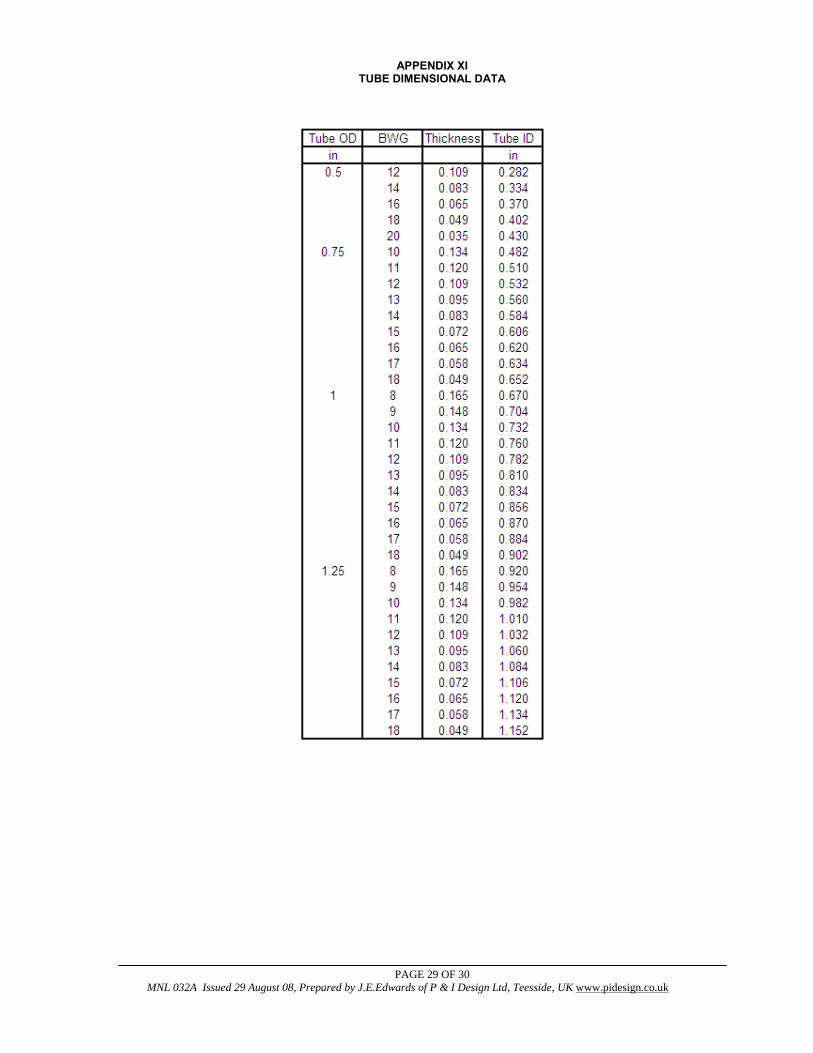
The most common sizes used are 3/4"od and 1"od Use smallest diameter for greater heat transfer area with a normal minimum of 3/4"od tube due to cleaning considerations and vibration.1/2"od tubes can be used on shorter tube lengths say < 4ft. The wall thickness is defined by the Birmingham wire gage (BWG) details are given in Appendix XI(Kern Table 10) Tube Number and Length
Select the number of tubes per tube side pass to give optimum velocity 3-5 ft/s (0.9-1.52 m/s) for liquids and reasonable gas velocities are 50-100 ft/s(15-30 m/s) If the velocity cannot be achieved in a single pass consider increasing the number of passes. Tube length is determined by heat transfer required subject to plant layout and pressure drop constraints. To meet the design pressure drop constraints may require an increase in the number of tubes and/or a reduction in tube length. Long tube lengths with few tubes may give rise to shell side distribution problems.
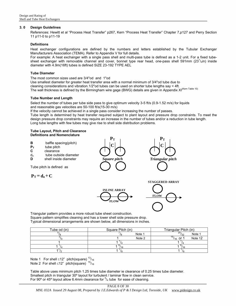
Tube Layout, Pitch and Clearance Definitions and Nomenclature B baffle spacing(pitch) PT tube pitch C clearance do tube outside diameter D shell inside diameter Tube pitch is defined as
CdP oT +=
Triangular pattern provides a more robust tube sheet construction. Square pattern simplifies cleaning and has a lower shell side pressure drop. Typical dimensional arrangements are shown below, all dimensions in inches.
Tube od (in) Square Pitch (in) Triangular Pitch (in) 5/8 7/8 Note 1 25/32 Note 1
3/4 1 Note 2 15/16 or 1 Note 12 1 1 1/4 1 1/4
1 1/4 1 9/16 1 9/16 11/2 1 7/8 1 7/8
Note 1 For shell ≤12” pitch(square) 13/16 Note 2 For shell ≤12” pitch(square) 15/16 Table above uses minimum pitch 1.25 times tube diameter ie clearance of 0.25 times tube diameter. Smallest pitch in triangular 30º layout for turbulent / laminar flow in clean service. For 90º or 45º layout allow 6.4mm clearance for 3/4 tube for ease of cleaning.
Triangular pitch
PT
C
FLOW
STAGGERED ARRAY
INLINE ARRAY
FLOW
PT
C
Square pitch
Design and Rating of Shell and Tube Heat Exchangers
PAGE 9 OF 30 MNL 032A Issued 29 August 08, Prepared by J.E.Edwards of P & I Design Ltd, Teesside, UK www.pidesign.co.uk
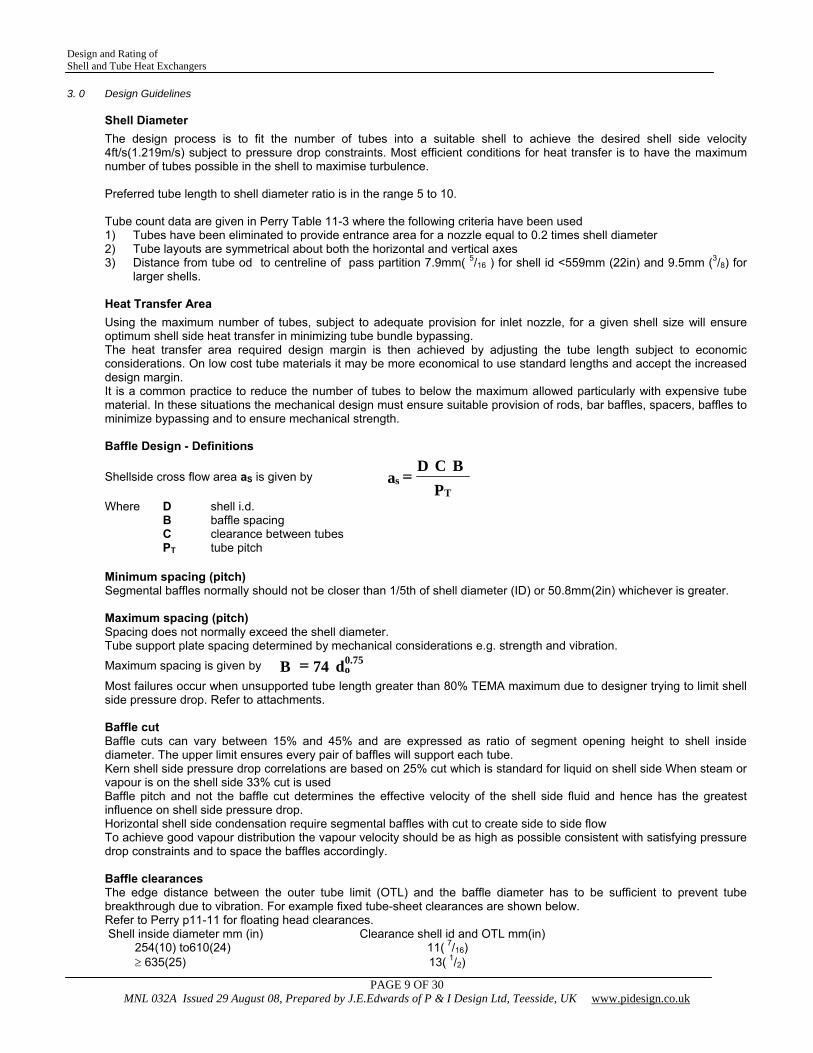
3. 0 Design Guidelines Shell Diameter
The design process is to fit the number of tubes into a suitable shell to achieve the desired shell side velocity 4ft/s(1.219m/s) subject to pressure drop constraints. Most efficient conditions for heat transfer is to have the maximum number of tubes possible in the shell to maximise turbulence. Preferred tube length to shell diameter ratio is in the range 5 to 10. Tube count data are given in Perry Table 11-3 where the following criteria have been used 1) Tubes have been eliminated to provide entrance area for a nozzle equal to 0.2 times shell diameter 2) Tube layouts are symmetrical about both the horizontal and vertical axes 3) Distance from tube od to centreline of pass partition 7.9mm( 5/16 ) for shell id <559mm (22in) and 9.5mm (3/8) for
larger shells. Heat Transfer Area
Using the maximum number of tubes, subject to adequate provision for inlet nozzle, for a given shell size will ensure optimum shell side heat transfer in minimizing tube bundle bypassing. The heat transfer area required design margin is then achieved by adjusting the tube length subject to economic considerations. On low cost tube materials it may be more economical to use standard lengths and accept the increased design margin. It is a common practice to reduce the number of tubes to below the maximum allowed particularly with expensive tube material. In these situations the mechanical design must ensure suitable provision of rods, bar baffles, spacers, baffles to minimize bypassing and to ensure mechanical strength. Baffle Design - Definitions
Shellside cross flow area aS is given by P
BCDa
Ts =
Where D shell i.d. B baffle spacing
C clearance between tubes PT tube pitch
Minimum spacing (pitch) Segmental baffles normally should not be closer than 1/5th of shell diameter (ID) or 50.8mm(2in) whichever is greater. Maximum spacing (pitch) Spacing does not normally exceed the shell diameter. Tube support plate spacing determined by mechanical considerations e.g. strength and vibration.
Maximum spacing is given by d74B 75.0o=
Most failures occur when unsupported tube length greater than 80% TEMA maximum due to designer trying to limit shell side pressure drop. Refer to attachments. Baffle cut Baffle cuts can vary between 15% and 45% and are expressed as ratio of segment opening height to shell inside diameter. The upper limit ensures every pair of baffles will support each tube. Kern shell side pressure drop correlations are based on 25% cut which is standard for liquid on shell side When steam or vapour is on the shell side 33% cut is used Baffle pitch and not the baffle cut determines the effective velocity of the shell side fluid and hence has the greatest influence on shell side pressure drop. Horizontal shell side condensation require segmental baffles with cut to create side to side flow To achieve good vapour distribution the vapour velocity should be as high as possible consistent with satisfying pressure drop constraints and to space the baffles accordingly. Baffle clearances The edge distance between the outer tube limit (OTL) and the baffle diameter has to be sufficient to prevent tube breakthrough due to vibration. For example fixed tube-sheet clearances are shown below. Refer to Perry p11-11 for floating head clearances. Shell inside diameter mm (in) Clearance shell id and OTL mm(in) 254(10) to610(24) 11( 7/16) ≥ 635(25) 13( 1/2)
Design and Rating of Shell and Tube Heat Exchangers
PAGE 10 OF 30 MNL 032A Issued 29 August 08, Prepared by J.E.Edwards of P & I Design Ltd, Teesside, UK www.pidesign.co.uk
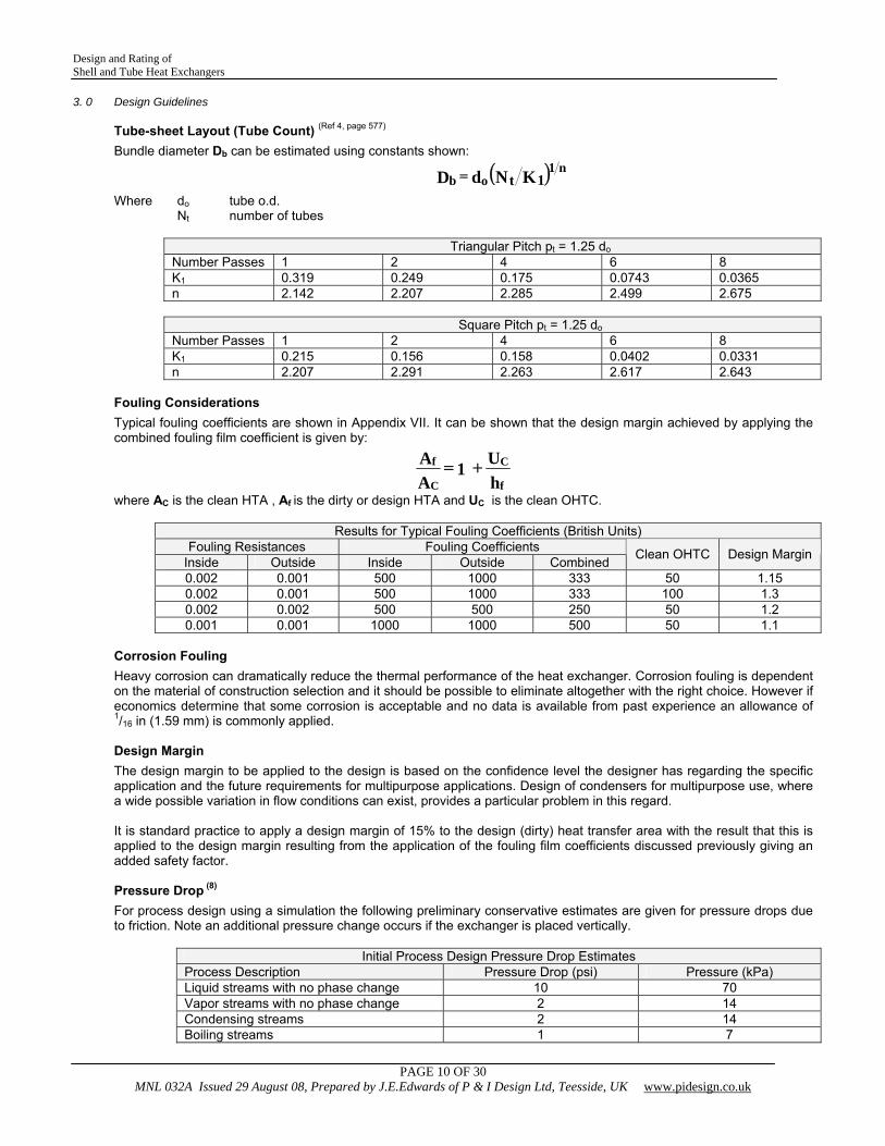
3. 0 Design Guidelines Tube-sheet Layout (Tube Count) (Ref 4, page 577)
Bundle diameter Db can be estimated using constants shown:
( )KNdD 1tn1
ob =
Where do tube o.d. Nt number of tubes
Triangular Pitch pt = 1.25 do Number Passes 1 2 4 6 8 K1 0.319 0.249 0.175 0.0743 0.0365 n 2.142 2.207 2.285 2.499 2.675
Square Pitch pt = 1.25 do
Number Passes 1 2 4 6 8 K1 0.215 0.156 0.158 0.0402 0.0331 n 2.207 2.291 2.263 2.617 2.643
Fouling Considerations
Typical fouling coefficients are shown in Appendix VII. It can be shown that the design margin achieved by applying the combined fouling film coefficient is given by:
hU1
AA
f
C
C
f +=
where AC is the clean HTA , Af is the dirty or design HTA and UC is the clean OHTC.
Results for Typical Fouling Coefficients (British Units) Fouling Resistances Fouling Coefficients
Inside Outside Inside Outside Combined Clean OHTC Design Margin
0.002 0.001 500 1000 333 50 1.15 0.002 0.001 500 1000 333 100 1.3 0.002 0.002 500 500 250 50 1.2 0.001 0.001 1000 1000 500 50 1.1
Corrosion Fouling
Heavy corrosion can dramatically reduce the thermal performance of the heat exchanger. Corrosion fouling is dependent on the material of construction selection and it should be possible to eliminate altogether with the right choice. However if economics determine that some corrosion is acceptable and no data is available from past experience an allowance of 1/16 in (1.59 mm) is commonly applied.
Design Margin
The design margin to be applied to the design is based on the confidence level the designer has regarding the specific application and the future requirements for multipurpose applications. Design of condensers for multipurpose use, where a wide possible variation in flow conditions can exist, provides a particular problem in this regard. It is standard practice to apply a design margin of 15% to the design (dirty) heat transfer area with the result that this is applied to the design margin resulting from the application of the fouling film coefficients discussed previously giving an added safety factor. Pressure Drop (8)
For process design using a simulation the following preliminary conservative estimates are given for pressure drops due to friction. Note an additional pressure change occurs if the exchanger is placed vertically.
Initial Process Design Pressure Drop Estimates
Process Description Pressure Drop (psi) Pressure (kPa) Liquid streams with no phase change 10 70 Vapor streams with no phase change 2 14 Condensing streams 2 14 Boiling streams 1 7
Design and Rating of Shell and Tube Heat Exchangers
PAGE 11 OF 30 MNL 032A Issued 29 August 08, Prepared by J.E.Edwards of P & I Design Ltd, Teesside, UK www.pidesign.co.uk
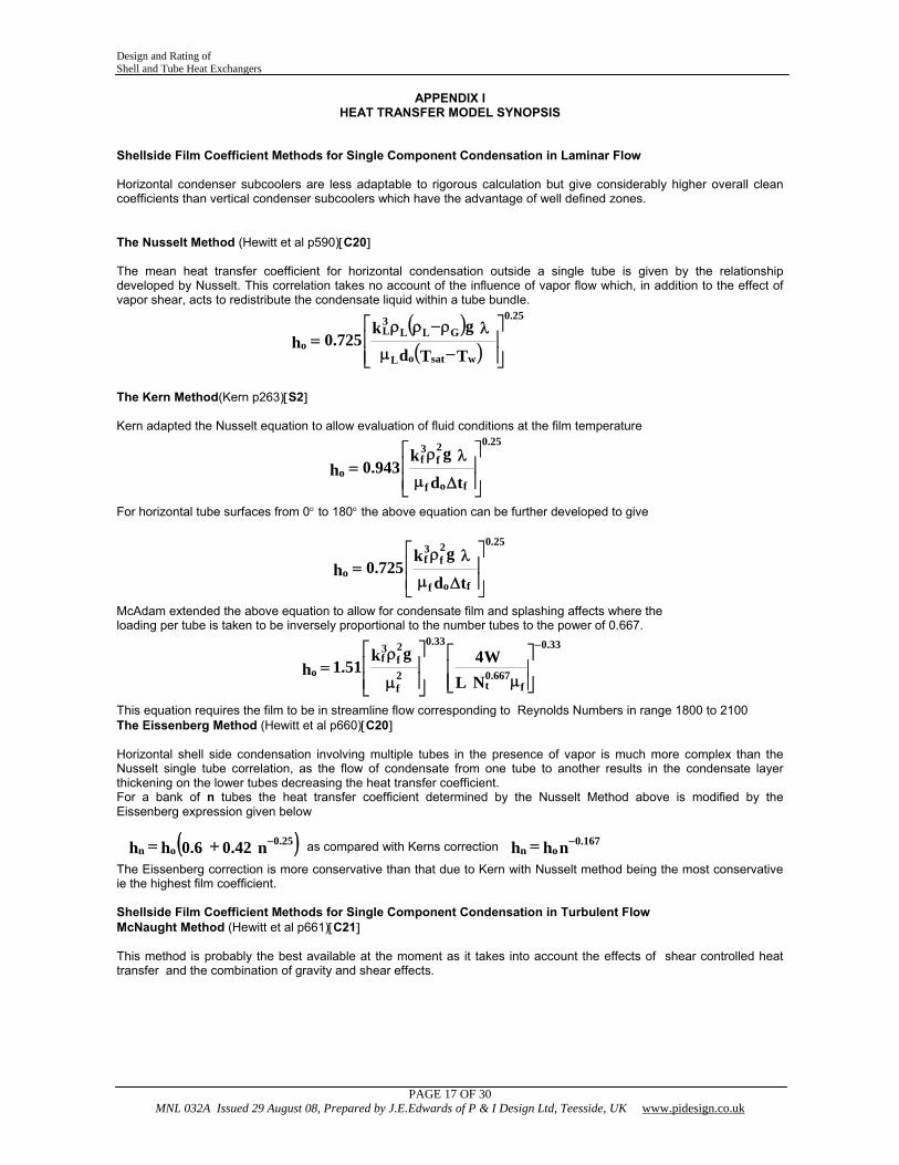
APPENDIX I HEAT TRANSFER MODEL SYNOPSIS
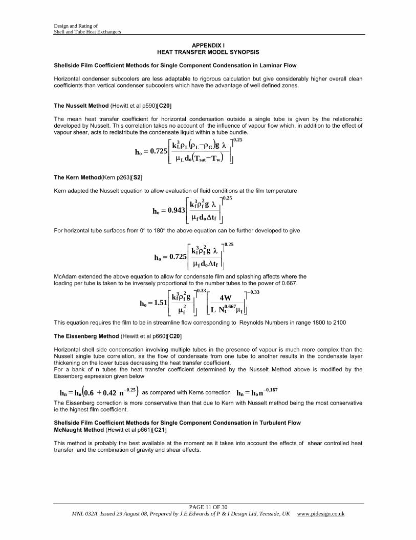
Shellside Film Coefficient Methods for Single Component Condensation in Laminar Flow Horizontal condenser subcoolers are less adaptable to rigorous calculation but give considerably higher overall clean coefficients than vertical condenser subcoolers which have the advantage of well defined zones. The Nusselt Method (Hewitt et al p590)[C20] The mean heat transfer coefficient for horizontal condensation outside a single tube is given by the relationship developed by Nusselt. This correlation takes no account of the influence of vapour flow which, in addition to the effect of vapour shear, acts to redistribute the condensate liquid within a tube bundle.
( )( ) ⎥
⎥⎦
⎤
⎢⎢⎣
⎡
−μ
λρ−ρρ=
TTd
gk725.0h
wsatoL
GLL3L
25.0
o
The Kern Method(Kern p263)[S2] Kern adapted the Nusselt equation to allow evaluation of fluid conditions at the film temperature
⎥⎥⎦
⎤
⎢⎢⎣
⎡
Δμ
λρ=
td
gk943.0h
fof
2f
3f
25.0
o
For horizontal tube surfaces from 0° to 180° the above equation can be further developed to give
⎥⎥⎦
⎤
⎢⎢⎣
⎡
Δμ
λρ=
td
gk725.0h
fof
2f
3f
25.0
o
McAdam extended the above equation to allow for condensate film and splashing affects where the loading per tube is taken to be inversely proportional to the number tubes to the power of 0.667.
⎥⎥⎦
⎤
⎢⎢⎣
⎡
μ⎥⎥⎦
⎤
⎢⎢⎣
⎡
μ
ρ=
−
f667.0
t
33.0
2f
2f
3f
33.0
oNL
W4gk51.1h
This equation requires the film to be in streamline flow corresponding to Reynolds Numbers in range 1800 to 2100 The Eissenberg Method (Hewitt et al p660)[C20] Horizontal shell side condensation involving multiple tubes in the presence of vapour is much more complex than the Nusselt single tube correlation, as the flow of condensate from one tube to another results in the condensate layer thickening on the lower tubes decreasing the heat transfer coefficient. For a bank of n tubes the heat transfer coefficient determined by the Nusselt Method above is modified by the Eissenberg expression given below
( )n42.06.0hh 25.0on
−+= as compared with Kerns correction nhh 167.0on
−=
The Eissenberg correction is more conservative than that due to Kern with Nusselt method being the most conservative ie the highest film coefficient. Shellside Film Coefficient Methods for Single Component Condensation in Turbulent Flow McNaught Method (Hewitt et al p661)[C21] This method is probably the best available at the moment as it takes into account the effects of shear controlled heat transfer and the combination of gravity and shear effects.
Design and Rating of Shell and Tube Heat Exchangers
PAGE 12 OF 30 MNL 032A Issued 29 August 08, Prepared by J.E.Edwards of P & I Design Ltd, Teesside, UK www.pidesign.co.uk
APPENDIX I HEAT TRANSFER MODEL SYNOPSIS
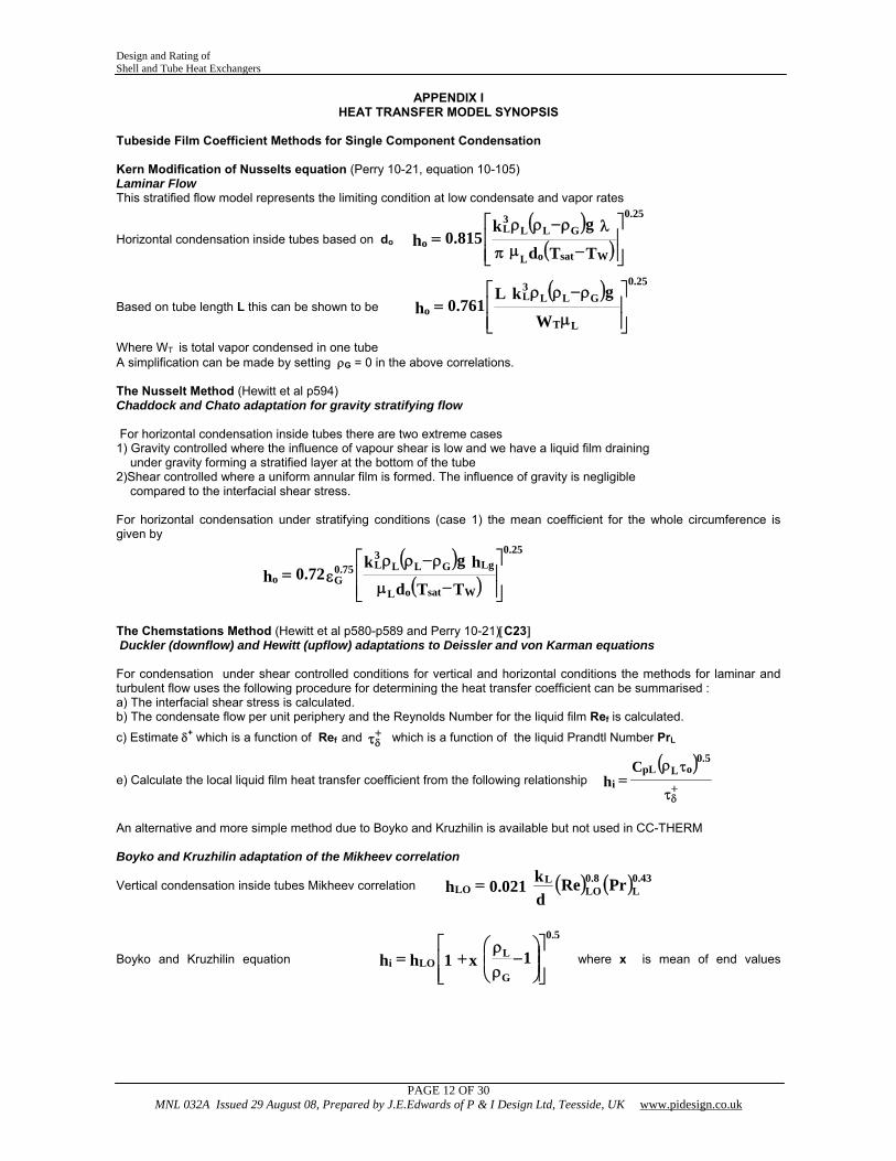
Tubeside Film Coefficient Methods for Single Component Condensation Kern Modification of Nusselts equation (Perry 10-21, equation 10-105) Laminar Flow This stratified flow model represents the limiting condition at low condensate and vapor rates
Horizontal condensation inside tubes based on do ( )( ) ⎥
⎥⎦
⎤
⎢⎢⎣
⎡
−μπ
λρ−ρρ=
TTd
gk815.0h
WsatoL
GLL3L
25.0
o
Based on tube length L this can be shown to be ( )
⎥⎥⎦
⎤
⎢⎢⎣
⎡
μ
ρ−ρρ=
W
gkL761.0h
T L
GLL3L
25.0
o
Where WT is total vapor condensed in one tube A simplification can be made by setting ρG = 0 in the above correlations. The Nusselt Method (Hewitt et al p594) Chaddock and Chato adaptation for gravity stratifying flow For horizontal condensation inside tubes there are two extreme cases 1) Gravity controlled where the influence of vapour shear is low and we have a liquid film draining under gravity forming a stratified layer at the bottom of the tube 2)Shear controlled where a uniform annular film is formed. The influence of gravity is negligible compared to the interfacial shear stress. For horizontal condensation under stratifying conditions (case 1) the mean coefficient for the whole circumference is given by
( )( ) ⎥
⎥⎦
⎤
⎢⎢⎣
⎡
−μ
ρ−ρρε=
TTd
hgk72.0h
WsatoL
LgGLL3L
25.0
75.0Go
The Chemstations Method (Hewitt et al p580-p589 and Perry 10-21)[C23] Duckler (downflow) and Hewitt (upflow) adaptations to Deissler and von Karman equations For condensation under shear controlled conditions for vertical and horizontal conditions the methods for laminar and turbulent flow uses the following procedure for determining the heat transfer coefficient can be summarised : a) The interfacial shear stress is calculated. b) The condensate flow per unit periphery and the Reynolds Number for the liquid film Ref is calculated.
c) Estimate δ+ which is a function of Ref and τ+δ which is a function of the liquid Prandtl Number PrL
e) Calculate the local liquid film heat transfer coefficient from the following relationship ( )τ
τρ=
+δ
oL5.0
pLi
Ch
An alternative and more simple method due to Boyko and Kruzhilin is available but not used in CC-THERM Boyko and Kruzhilin adaptation of the Mikheev correlation
Vertical condensation inside tubes Mikheev correlation ( ) ( )PrRedk021.0h 43.0
L8.0
LOL
LO =
Boyko and Kruzhilin equation ⎥⎥⎦
⎤
⎢⎢⎣
⎡⎟⎟⎠
⎞⎜⎜⎝
⎛−
ρρ
+= 1x1hhG
L
5.0
LOi where x is mean of end values
Design and Rating of Shell and Tube Heat Exchangers
PAGE 13 OF 30 MNL 032A Issued 29 August 08, Prepared by J.E.Edwards of P & I Design Ltd, Teesside, UK www.pidesign.co.uk
APPENDIX I HEAT TRANSFER MODEL SYNOPSIS
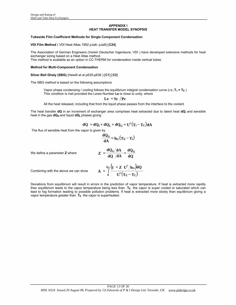
Tubeside Film Coefficient Methods for Single Component Condensation VDI Film Method ( VDI Heat Atlas 1992 pJa6- pJa8) [C24] The Association of German Engineers (Verein Deutscher Ingenieure, VDI ) have developed extensive methods for heat exchanger sizing based on a Heat Atlas method. This method is available as an option in CC-THERM for condensation inside vertical tubes. Method for Multi-Component Condensation Silver Bell Ghaly (SBG) (Hewitt et al p635-p636 ) [C1] [C2] The SBG method is based on the following assumptions
Vapor phase condensing / cooling follows the equilibrium integral condensation curve (i.e.,Tv = TE ) This condition is met provided the Lewis Number Le is close to unity, where PrScLe =
All the heat released, including that from the liquid phase passes from the interface to the coolant The heat transfer dQ in an increment of exchanger area comprises heat extracted due to latent heat dQl and sensible heat in the gas dQG and liquid dQL phases giving
( )dATTUdQdQdQdQ Cii
GLl −=++=
The flux of sensible heat from the vapor is given by
( )TThdAdQ
iEGG −=
We define a parameter Z where dQdQ
dAdQdAdQ
Z GG ==
Combining with the above we can show ( )
( )∫−
+=
Q
0 CEi
Gi
T
TTU
dQhUZ1A
Deviations from equilibrium will result in errors in the prediction of vapor temperature. If heat is extracted more rapidly than equilibrium leads to the vapor temperature being less than TE the vapor is super cooled or saturated which can lead to fog formation leading to possible pollution problems. If heat is extracted more slowly than equilibrium giving a vapor temperature greater than TE the vapor is superheated.
Design and Rating of Shell and Tube Heat Exchangers
PAGE 14 OF 30 MNL 032A Issued 29 August 08, Prepared by J.E.Edwards of P & I Design Ltd, Teesside, UK www.pidesign.co.uk
APPENDIX I
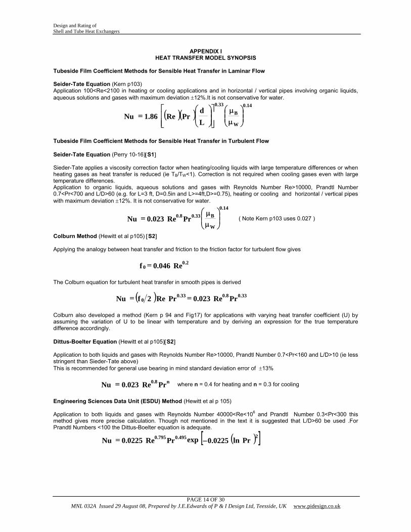
HEAT TRANSFER MODEL SYNOPSIS Tubeside Film Coefficient Methods for Sensible Heat Transfer in Laminar Flow Seider-Tate Equation (Kern p103) Application 100<Re<2100 in heating or cooling applications and in horizontal / vertical pipes involving organic liquids, aqueous solutions and gases with maximum deviation ±12%.It is not conservative for water.
( )( ) ⎟⎟⎠
⎞⎜⎜⎝
⎛
μμ
⎥⎥⎦
⎤
⎢⎢⎣
⎡⎟⎟⎠
⎞⎜⎜⎝
⎛=
W
B14.033.0
Ld
PrRe86.1Nu
Tubeside Film Coefficient Methods for Sensible Heat Transfer in Turbulent Flow Seider-Tate Equation (Perry 10-16)[S1] Sieder-Tate applies a viscosity correction factor when heating/cooling liquids with large temperature differences or when heating gases as heat transfer is reduced (ie TB/TW<1). Correction is not required when cooling gases even with large temperature differences. Application to organic liquids, aqueous solutions and gases with Reynolds Number Re>10000, Prandtl Number 0.7<Pr<700 and L/D>60 (e.g. for L=3 ft, D=0.5in and L>=4ft,D>=0.75), heating or cooling and horizontal / vertical pipes with maximum deviation ±12%. It is not conservative for water.
⎟⎟⎠
⎞⎜⎜⎝
⎛
μμ
=W
B14.0
33.08.0 PrRe023.0Nu ( Note Kern p103 uses 0.027 )
Colburn Method (Hewitt et al p105) [S2] Applying the analogy between heat transfer and friction to the friction factor for turbulent flow gives
Re046.0f 2.00 =
The Colburn equation for turbulent heat transfer in smooth pipes is derived
( ) PrRe023.0PrRe2fNu 33.08.033.00 ==
Colburn also developed a method (Kern p 94 and Fig17) for applications with varying heat transfer coefficient (U) by assuming the variation of U to be linear with temperature and by deriving an expression for the true temperature difference accordingly. Dittus-Boelter Equation (Hewitt et al p105)[S2] Application to both liquids and gases with Reynolds Number Re>10000, Prandtl Number 0.7<Pr<160 and L/D>10 (ie less stringent than Sieder-Tate above) This is recommended for general use bearing in mind standard deviation error of ±13%
PrRe023.0Nu n8.0= where n = 0.4 for heating and n = 0.3 for cooling
Engineering Sciences Data Unit (ESDU) Method (Hewitt et al p 105) Application to both liquids and gases with Reynolds Number 40000<Re<106 and Prandtl Number 0.3<Pr<300 this method gives more precise calculation. Though not mentioned in the text it is suggested that L/D>60 be used .For Prandtl Numbers <100 the Dittus-Boelter equation is adequate.
( )[ ]Prln0225.0expPrRe0225.0Nu2495.0795.0 −=
Design and Rating of Shell and Tube Heat Exchangers
PAGE 15 OF 30 MNL 032A Issued 29 August 08, Prepared by J.E.Edwards of P & I Design Ltd, Teesside, UK www.pidesign.co.uk
APPENDIX I HEAT TRANSFER MODEL SYNOPSIS
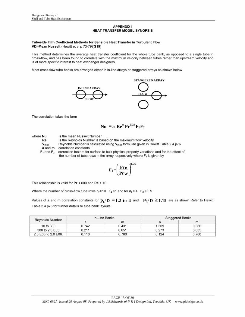
Tubeside Film Coefficient Methods for Sensible Heat Transfer in Turbulent Flow VDI-Mean Nusselt (Hewitt et al p 73-79)[S19] This method determines the average heat transfer coefficient for the whole tube bank, as opposed to a single tube in cross-flow, and has been found to correlate with the maximum velocity between tubes rather than upstream velocity and is of more specific interest to heat exchanger designers. Most cross-flow tube banks are arranged either in in-line arrays or staggered arrays as shown below The correlation takes the form
FFPrReaNu 2134.0m=
where Nu is the mean Nusselt Number Re is the Reynolds Number is based on the maximum flow velocity Vmax Reynolds Number is calculated using Vmax formulae given in Hewitt Table 2.4 p76 a and m correlation constants F1 and F2 correction factors for surface to bulk physical property variations and for the effect of the number of tube rows in the array respectively where F1 is given by This relationship is valid for Pr < 600 and Re > 10 Where the number of cross-flow tube rows nr >10 F2 ≅1 and for nr = 4 F2 ≅ 0.9 Values of a and m correlation constants for 4to2.1Dp1 = and 15.1DP2 ≥ are as shown Refer to Hewitt
Table 2.4 p76 for further details re tube bank layouts.
In-Line Banks Staggered Banks Reynolds Number a m a m 10 to 300 0.742 0.431 1.309 0.360
300 to 2.0 E05 0.211 0.651 0.273 0.635 2.0 E05 to 2.0 E06. 0.116 0.700 0.124 0.700
FLOW
STAGGERED ARRAY
INLINE ARRAY
FLOW
⎟⎟⎠
⎞⎜⎜⎝
⎛=
PrPrF
W
B26.0
1
Design and Rating of Shell and Tube Heat Exchangers
PAGE 16 OF 30 MNL 032A Issued 29 August 08, Prepared by J.E.Edwards of P & I Design Ltd, Teesside, UK www.pidesign.co.uk
APPENDIX I HEAT TRANSFER MODEL SYNOPSIS
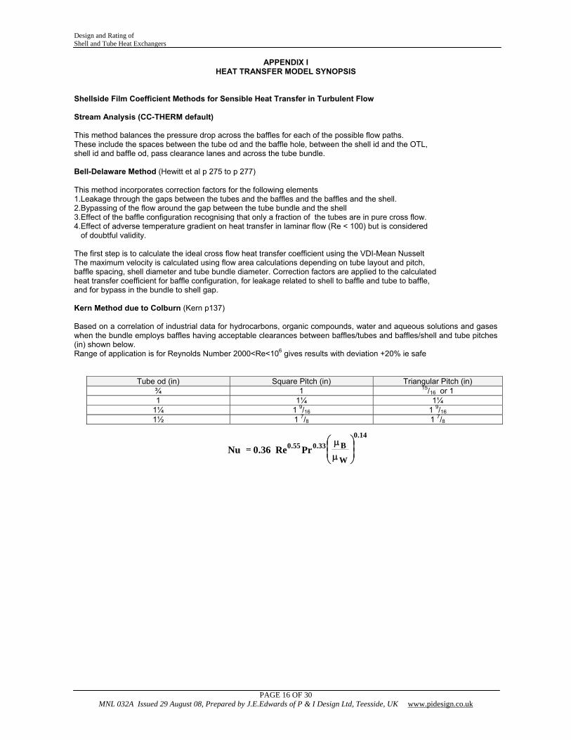
Shellside Film Coefficient Methods for Sensible Heat Transfer in Turbulent Flow Stream Analysis (CC-THERM default) This method balances the pressure drop across the baffles for each of the possible flow paths. These include the spaces between the tube od and the baffle hole, between the shell id and the OTL, shell id and baffle od, pass clearance lanes and across the tube bundle. Bell-Delaware Method (Hewitt et al p 275 to p 277) This method incorporates correction factors for the following elements 1.Leakage through the gaps between the tubes and the baffles and the baffles and the shell. 2.Bypassing of the flow around the gap between the tube bundle and the shell 3.Effect of the baffle configuration recognising that only a fraction of the tubes are in pure cross flow. 4.Effect of adverse temperature gradient on heat transfer in laminar flow (Re < 100) but is considered of doubtful validity. The first step is to calculate the ideal cross flow heat transfer coefficient using the VDI-Mean Nusselt The maximum velocity is calculated using flow area calculations depending on tube layout and pitch, baffle spacing, shell diameter and tube bundle diameter. Correction factors are applied to the calculated heat transfer coefficient for baffle configuration, for leakage related to shell to baffle and tube to baffle, and for bypass in the bundle to shell gap. Kern Method due to Colburn (Kern p137) Based on a correlation of industrial data for hydrocarbons, organic compounds, water and aqueous solutions and gases when the bundle employs baffles having acceptable clearances between baffles/tubes and baffles/shell and tube pitches (in) shown below. Range of application is for Reynolds Number 2000<Re<106 gives results with deviation +20% ie safe
Tube od (in) Square Pitch (in) Triangular Pitch (in) ¾ 1 15/16 or 1 1 1¼ 1¼
1¼ 1 9/16 1 9/16 1½ 1 7/8 1 7/8
⎟⎟⎠
⎞⎜⎜⎝
⎛
μμ
=W
B14.0
33.055.0 PrRe36.0Nu
Design and Rating of Shell and Tube Heat Exchangers
PAGE 17 OF 30 MNL 032A Issued 29 August 08, Prepared by J.E.Edwards of P & I Design Ltd, Teesside, UK www.pidesign.co.uk
APPENDIX I HEAT TRANSFER MODEL SYNOPSIS
Shellside Film Coefficient Methods for Single Component Condensation in Laminar Flow Horizontal condenser subcoolers are less adaptable to rigorous calculation but give considerably higher overall clean coefficients than vertical condenser subcoolers which have the advantage of well defined zones. The Nusselt Method (Hewitt et al p590)[C20] The mean heat transfer coefficient for horizontal condensation outside a single tube is given by the relationship developed by Nusselt. This correlation takes no account of the influence of vapor flow which, in addition to the effect of vapor shear, acts to redistribute the condensate liquid within a tube bundle.
( )( ) ⎥
⎥⎦
⎤
⎢⎢⎣
⎡
−μ
λρ−ρρ=
TTd
gk725.0h
wsatoL
GLL3L
25.0
o
The Kern Method(Kern p263)[S2] Kern adapted the Nusselt equation to allow evaluation of fluid conditions at the film temperature
⎥⎥⎦
⎤
⎢⎢⎣
⎡
Δμ
λρ=
td
gk943.0h
fof
2f
3f
25.0
o
For horizontal tube surfaces from 0° to 180° the above equation can be further developed to give
⎥⎥⎦
⎤
⎢⎢⎣
⎡
Δμ
λρ=
td
gk725.0h
fof
2f
3f
25.0
o
McAdam extended the above equation to allow for condensate film and splashing affects where the loading per tube is taken to be inversely proportional to the number tubes to the power of 0.667.
⎥⎥⎦
⎤
⎢⎢⎣
⎡
μ⎥⎥⎦
⎤
⎢⎢⎣
⎡
μ
ρ=
−
f667.0
t
33.0
2f
2f
3f
33.0
oNL
W4gk51.1h
This equation requires the film to be in streamline flow corresponding to Reynolds Numbers in range 1800 to 2100 The Eissenberg Method (Hewitt et al p660)[C20] Horizontal shell side condensation involving multiple tubes in the presence of vapor is much more complex than the Nusselt single tube correlation, as the flow of condensate from one tube to another results in the condensate layer thickening on the lower tubes decreasing the heat transfer coefficient. For a bank of n tubes the heat transfer coefficient determined by the Nusselt Method above is modified by the Eissenberg expression given below
( )n42.06.0hh 25.0on
−+= as compared with Kerns correction nhh 167.0on
−=
The Eissenberg correction is more conservative than that due to Kern with Nusselt method being the most conservative ie the highest film coefficient. Shellside Film Coefficient Methods for Single Component Condensation in Turbulent Flow McNaught Method (Hewitt et al p661)[C21] This method is probably the best available at the moment as it takes into account the effects of shear controlled heat transfer and the combination of gravity and shear effects.
Design and Rating of Shell and Tube Heat Exchangers
PAGE 18 OF 30 MNL 032A Issued 29 August 08, Prepared by J.E.Edwards of P & I Design Ltd, Teesside, UK www.pidesign.co.uk
APPENDIX II CC-THERM USER GUIDELINES
Design Optimisation CC-THERM always searches from a small size to a large size which ensures the minimum possible excess area consistent with satisfying the user specified shell side and tube side pressure drop and velocity design constraints. If design is pressure drop or velocity limited leading to an oversized area the user can relax the pressure drop and/or the velocity design constraint and possibly adjust tube pitch or diameter to make the design a heat transfer area limited design. CC-THERM issues a message at the end of its search advising if the design is pressure drop, velocity or area limited to assist in the optimization process. The heat exchanger design can be forced by setting design limits to constrain certain parameters. For example restricting tube length to meet an installation constraint will result in an increase in the number of tubes and hence shell diameter. Standard shell sizes are used so an increase in diameter from 8” to 10” could lead to an oversize of 56% derived from the increase in shell area ratio. To achieve final design optimisation the user should switch to the rating mode and adjust tube length until the desired area safety margin has been achieved. Tube Counts For a selected shell diameter, tube design parameters (diameter, pitch, layout) and clearances there is a limit to the number of tubes that can fit determined by the outer tube limits (OTL). Standard tube count tables are provided in Perry Table 11-3 and CC-THERM will always use these values if standard tube sizes are specified in Imperial units. If the design is based on Metric units the user should ensure a practical design has been achieved in regards to tube counts. The table value can be achieved by entering the Imperial size exactly in Metric e.g. ¾” entered as 19.05mm not 19mm. LMTD When running UnitOp HEATEX in CHEMCAD the LMTD is based on the inlet and outlet temperatures. CC-THERM LMTD is based on a zone by zone computation resulting in an overall LMTD being a weighted mean average by zone heat load hence the two values will be different. Heat Exchanger Layout When specifying multiple pass configurations in CHEMCAD UnitOp HEATEX this information is not passed on to CC-THERM; the user needs to re-enter this information. User Specified Components For a new component the designer is normally provided with physical properties at the inlet and outlet conditions only. Pure regression can be carried out using two data points only for viscosity, specific heat and thermal conductivity. Density regressions will sometimes require forcing (set weighting at high value e.g. 106 for a given data point) or to change the library equation in the density parameter to a simpler form e.g. linear between close limits and set the data limit values.
PAGE 19 OF 30 MNL 032A Issued 29 August 08, Prepared by J.E.Edwards of P & I Design Ltd, Teesside, UK www.pidesign.co.uk
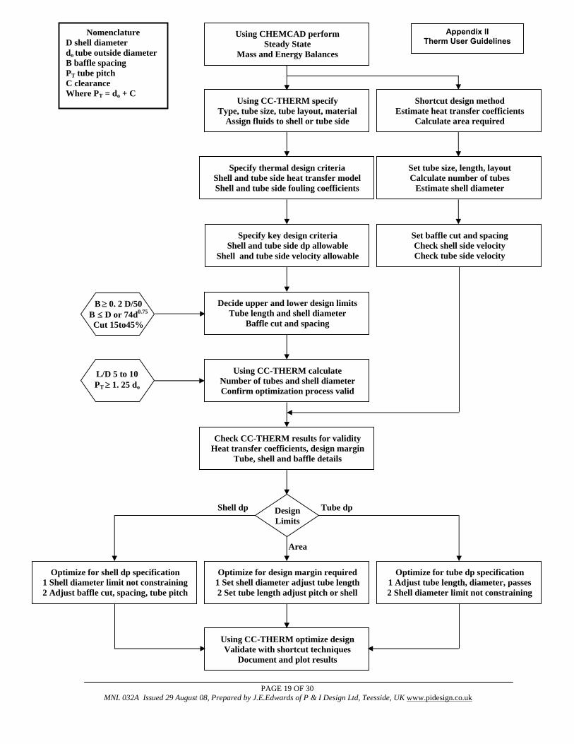
B ≥ 0. 2 D/50 B ≤ D or 74d0.75
Cut 15to45%
Decide upper and lower design limits Tube length and shell diameter
Baffle cut and spacing
Using CC-THERM calculate Number of tubes and shell diameter Confirm optimization process valid
Check CC-THERM results for validity Heat transfer coefficients, design margin
Tube, shell and baffle details
Design Limits
Optimize for design margin required 1 Set shell diameter adjust tube length 2 Set tube length adjust pitch or shell
Optimize for shell dp specification 1 Shell diameter limit not constraining 2 Adjust baffle cut, spacing, tube pitch
Optimize for tube dp specification 1 Adjust tube length, diameter, passes 2 Shell diameter limit not constraining
Using CC-THERM optimize design Validate with shortcut techniques
Document and plot results
Using CHEMCAD perform Steady State
Mass and Energy Balances
Using CC-THERM specify Type, tube size, tube layout, material
Assign fluids to shell or tube side
Specify key design criteria Shell and tube side dp allowable
Shell and tube side velocity allowable
Specify thermal design criteria Shell and tube side heat transfer model Shell and tube side fouling coefficients
Area
Shell dp Tube dp
Shortcut design method Estimate heat transfer coefficients
Calculate area required
Set tube size, length, layout Calculate number of tubes
Estimate shell diameter
Set baffle cut and spacing Check shell side velocity Check tube side velocity
L/D 5 to 10 PT ≥ 1. 25 do
Nomenclature D shell diameter do tube outside diameter B baffle spacing PT tube pitch C clearance Where PT = do + C
Appendix IITherm User Guidelines
SHELLSIDETUBESIDE
SILVER
BELL GHALY TUBESIDESHELLSIDE
VERTICALHORIZONTAL
SINGLEMULTI
COMPONENT
TURBULENTLAMINAR
FLOW
NUSSELT
MCNAUGHT
METHOD
CHEMSTATIONS METHOD DUCKLER & HEWITT
CONDENSATION SENSIBLE
HEAT TRANSFER
GEOMETRY
TURBULENTLAMINAR
EUBANK
PROCTOR
FLOW
SHEAR
ANNULAR GRAVITY
STRATIFYING FLOW
CHADDOCK
& CHATO
CHEMSTATIONS METHOD DUCKLER & HEWITT
GEOMETRY
ORIENTATION
VDI MEAN NUSSELT
SIEDER
TATE
COLBURN METHOD
DITTUS
BOELTER
ESDU
METHOD
VDI MEAN NUSSELT
THE
EISSENBERG
KERNS
METHOD
TABOREK METHOD
NUSSELT
STREAM
ANALYSIS
KERN
METHOD
BELL
DELAWARE
VDI FILM METHOD
PROGRAM
SELECT Re ≤ 1000 Re > 1000
Re ≤ 2000 Re > 10000
CC-THERM DEFAULT
MODE
Appendix III Therm Model Selection
PAGE 21 OF 30 MNL 032A Issued 29 August 08, Prepared by J.E.Edwards of P & I Design Ltd, Teesside, UK www.pidesign.co.uk
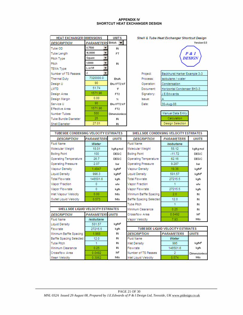
APPENDIX IV SHORTCUT HEAT EXCHANGER DESIGN
PAGE 22 OF 30 MNL 032A Issued 29 August 08, Prepared by J.E.Edwards of P & I Design Ltd, Teesside, UK www.pidesign.co.uk
APPENDIX V
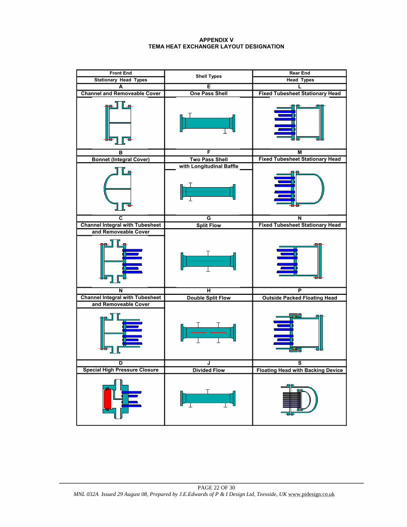
TEMA HEAT EXCHANGER LAYOUT DESIGNATION
TEMA HEAT EXCHANGER LAYOUTS
PChannel Integral with Tubesheet
and Removeable Cover
H
B F MBonnet (Integral Cover) Two Pass Shell
with Longitudinal BaffleFixed Tubesheet Stationary Head
Front EndStationary Head Types
AChannel and Removeable Cover
CChannel Integral with Tubesheet
and Removeable Cover
N
DSpecial High Pressure Closure
J
Rear End Head Types
LFixed Tubesheet Stationary Head
Shell Types
EOne Pass Shell
NFixed Tubesheet Stationary Head
GSplit Flow
S
Double Split Flow
Divided Flow
Outside Packed Floating Head
Floating Head with Backing Device

PAGE 23 OF 30 MNL 032A Issued 29 August 08, Prepared by J.E.Edwards of P & I Design Ltd, Teesside, UK www.pidesign.co.uk
APPENDIX V TEMA HEAT EXCHANGER LAYOUT DESIGNATION
Floating Tubesheet
Cross Flow U-Tube Bundle
WExternally Sealed
X U
KKettle Type Reboiler
TPull Through Floating Head
TEMA CLASS APPLICATIONR Severe requirements of petroleum and related process applicationsC Moderate requirements of commercial and general process applicationsB Chemical process service
PAGE 24 OF 30 MNL 032A Issued 29 August 08, Prepared by J.E.Edwards of P & I Design Ltd, Teesside, UK www.pidesign.co.uk
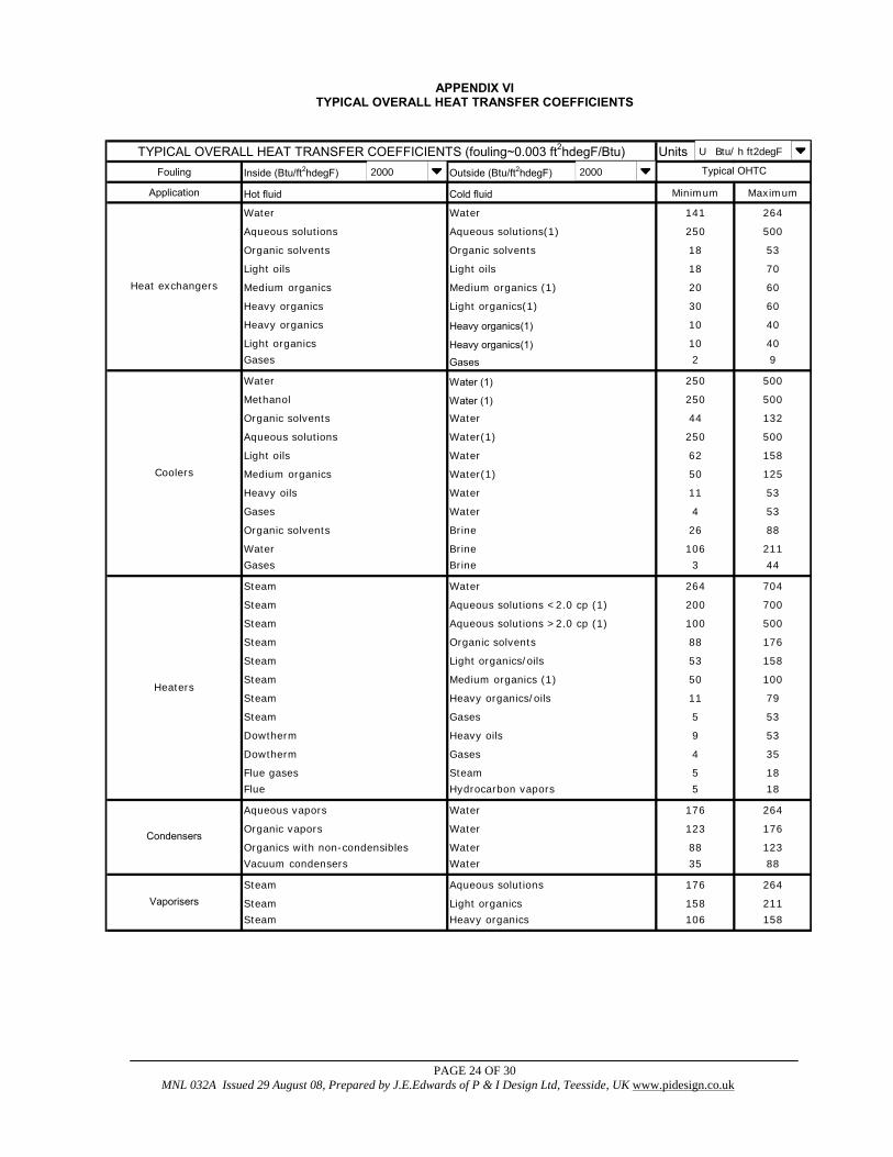
APPENDIX VI
TYPICAL OVERALL HEAT TRANSFER COEFFICIENTS
UnitsFouling Inside (Btu/ft2hdegF) Outside (Btu/ft2hdegF)
Application Hot fluid Cold fluid Minimum Maximum
Water Water 141 264
Aqueous solutions Aqueous solutions(1) 250 500
Organic solvents Organic solvents 18 53
Light oils Light oils 18 70
Medium organics Medium organics (1) 20 60
Heavy organics Light organics(1) 30 60
Heavy organics Heavy organics(1) 10 40
Light organics Heavy organics(1) 10 40
Gases Gases 2 9
Water Water (1) 250 500
Methanol Water (1) 250 500
Organic solvents Water 44 132
Aqueous solutions Water(1) 250 500
Light oils Water 62 158
Medium organics Water(1) 50 125
Heavy oils Water 11 53
Gases Water 4 53
Organic solvents Brine 26 88
Water Brine 106 211
Gases Brine 3 44
Steam Water 264 704
Steam Aqueous solutions <2.0 cp (1) 200 700
Steam Aqueous solutions >2.0 cp (1) 100 500
Steam Organic solvents 88 176
Steam Light organics/oils 53 158
Steam Medium organics (1) 50 100
Steam Heavy organics/oils 11 79
Steam Gases 5 53
Dowtherm Heavy oils 9 53
Dowtherm Gases 4 35
Flue gases Steam 5 18
Flue Hydrocarbon vapors 5 18
Aqueous vapors Water 176 264
Organic vapors Water 123 176
Organics with non-condensibles Water 88 123
Vacuum condensers Water 35 88
Steam Aqueous solutions 176 264
Steam Light organics 158 211
Steam Heavy organics 106 158
Heat exchangers
Vaporisers
TYPICAL OVERALL HEAT TRANSFER COEFFICIENTS (fouling~0.003 ft2hdegF/Btu)
Coolers
Heaters
Condensers
Typical OHTC
U Btu/ h ft2degF
2000 2000
PAGE 25 OF 30 MNL 032A Issued 29 August 08, Prepared by J.E.Edwards of P & I Design Ltd, Teesside, UK www.pidesign.co.uk
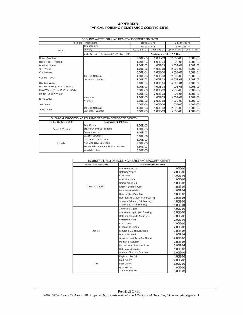
APPENDIX VII
TYPICAL FOULING RESISTANCE COEFFICIENTS
Temperature
Velocity Up to 3 ft/s Over 3 ft/s Up to 3 ft/s Over 3 ft/s
Unit Select
Boiler Blowdown 2.00E-03 2.00E-03 2.00E-03 2.00E-03Boiler Feed (Treated) 1.00E-03 5.00E-04 1.00E-03 1.00E-03Brackish Water 2.00E-03 1.00E-03 3.00E-03 2.00E-03City Water 1.00E-03 1.00E-03 2.00E-03 2.00E-03Condensate 5.00E-04 5.00E-04 5.00E-04 5.00E-04
Treated MakeUp 1.00E-03 1.00E-03 2.00E-03 2.00E-03Untreated MakeUp 3.00E-03 3.00E-03 5.00E-03 4.00E-03
Distilled Water 5.00E-04 5.00E-04 5.00E-04 5.00E-04Engine Jacket (Closed System) 1.00E-03 1.00E-03 1.00E-03 1.00E-03Hard Water (Over 15 Grains/Gal) 3.00E-03 3.00E-03 5.00E-03 5.00E-03Muddy Or Silty Water 3.00E-03 2.00E-03 4.00E-03 3.00E-03
Minimum 2.00E-03 1.00E-03 3.00E-03 2.00E-03Average 3.00E-03 2.00E-03 4.00E-03 3.00E-03
Sea Water 5.00E-04 5.00E-04 1.00E-03 1.00E-03Treated MakeUp 1.00E-03 1.00E-03 2.00E-03 2.00E-03Untreated MakeUp 3.00E-03 3.00E-03 5.00E-03 4.00E-03
Fouling Coefficient UnitsAcid Gases 2.50E-03Stable Overhead Products 1.00E-03Solvent Vapors 1.00E-03Caustic Solutions 2.00E-03DEG And TEG Solutions 2.00E-03MEA And DEA Solutions 2.00E-03Stable Side Draw and Bottom Product 1.50E-03Vegetable Oils 3.00E-03
Cooling Tower
River Water
Spray Pond
Water
Up to 125 °F Over 125 °F
Resistance ft2 h°F / Btu
COOLING WATER FOULING RESISTANCES/COEFFICIENTSHot Fluid Temperature Up to 240 °F 240 to 400 °F
CHEMICAL PROCESSING FOULING RESISTANCES/COEFFICIENTS
Gases & Vapors
Liquids
Resistance ft2 h°F / Btu
Resistance ft2 h°F / Btu
Fouling Coefficient UnitsAmmonia Vapor 1.00E-03Chlorine Vapor 2.00E-03CO2 Vapor 1.00E-03Coal Flue Gas 1.00E-02Compressed Air 1.00E-03Engine Exhaust Gas 1.00E-02Manufactured Gas 1.00E-02Natural Gas Flue Gas 5.00E-03Refrigerant Vapors (Oil Bearing) 2.00E-03Steam (Exhaust, Oil Bearing) 1.80E-03Steam (Non-Oil Bearing) 5.00E-04Ammonia Liquid 1.00E-03Ammonia Liquid (Oil Bearing) 3.00E-03Calcium Chloride Solutions 3.00E-03Chlorine Liquid 2.00E-03CO2 Liquid 1.00E-03Ethanol Solutions 2.00E-03Ethylene Glycol Solutions 2.00E-03Hydraulic Fluid 1.00E-03Organic Heat Transfer Media 2.00E-03Methanol Solutions 2.00E-03Molten Heat Transfer Salts 5.00E-04Refrigerant Liquids 1.00E-03Sodium Chloride Solutions 3.00E-03Engine Lube Oil 1.00E-03Fuel Oil #2 2.00E-03Fuel Oil #6 5.00E-03Quench Oil 4.00E-03Transformer Oil 1.00E-03
Liquids
Oils
INDUSTRIAL FLUIDS FOULING RESISTANCES/COEFFICIENTS
Gases & Vapors
Resistance ft2 h°F / Btu
PAGE 26 OF 30 MNL 032A Issued 29 August 08, Prepared by J.E.Edwards of P & I Design Ltd, Teesside, UK www.pidesign.co.uk
APPENDIX VIII LMTD CORRECTION FACTOR Ft
Ft Correction Factor for a 1 – n Heat Exchanger (where n is even)
PAGE 27 OF 30 MNL 032A Issued 29 August 08, Prepared by J.E.Edwards of P & I Design Ltd, Teesside, UK www.pidesign.co.uk
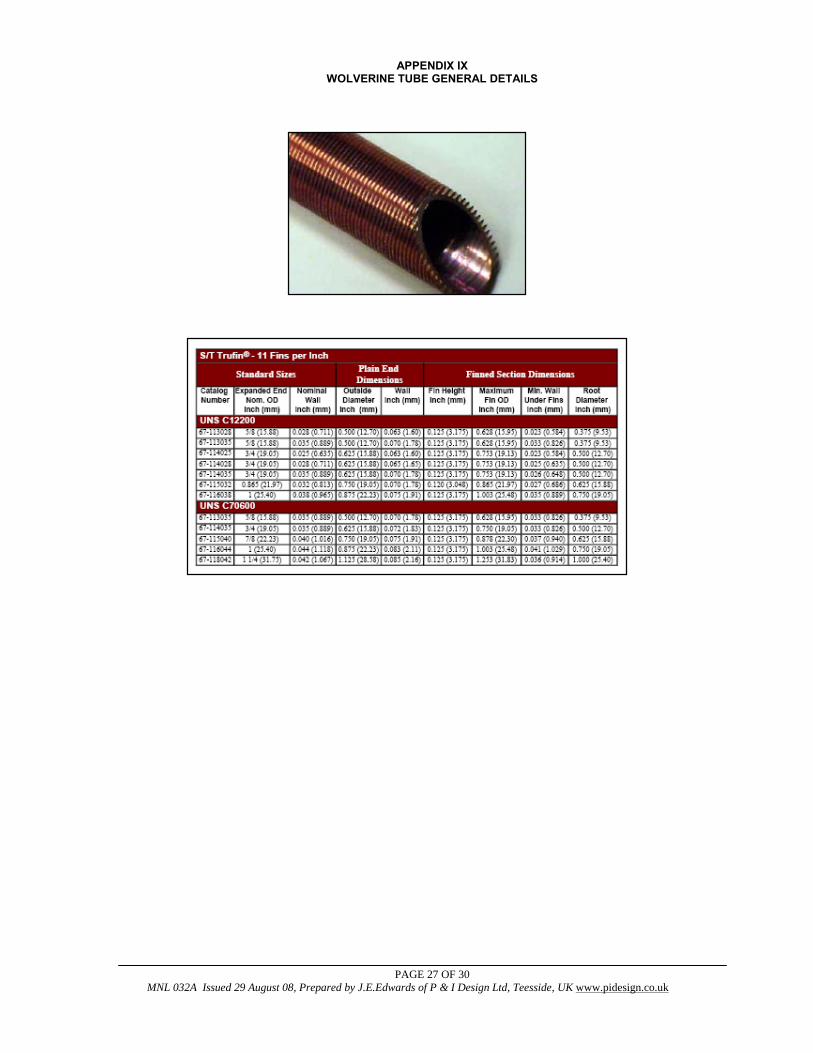
APPENDIX IX WOLVERINE TUBE GENERAL DETAILS
PAGE 28 OF 30 MNL 032A Issued 29 August 08, Prepared by J.E.Edwards of P & I Design Ltd, Teesside, UK www.pidesign.co.uk
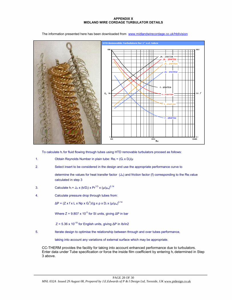
APPENDIX X MIDLAND WIRE CORDAGE TURBULATOR DETAILS
The information presented here has been downloaded from www.midlandwirecordage.co.uk/htdivision
To calculate hi for fluid flowing through tubes using HTD removable turbulators proceed as follows:
1. Obtain Reynolds Number in plain tube: Rei = (Gi x Di)/μ
2. Select insert to be considered in the design and use the appropriate performance curve to
determine the values for heat transfer factor (JH) and friction factor (f) corresponding to the Rei value calculated in step 3
3. Calculate hi = JH x (k/Di) x Pr1/3 x (μ/μw)0.14
4. Calculate pressure drop through tubes from:
ΔP = (Z x f x L x Np x Gi2)/(g x ρ x Di x (μ/μw)0.14
Where Z = 9.807 x 10⁻⁵ for SI units, giving ΔP in bar Z = 5.36 x 10⁻¹⁰ for English units, giving ΔP in Ib/in2
5. Iterate design to optimise the relationship between through and over tubes performance,
taking into account any variations of external surface which may be appropriate.
CC-THERM provides the facility for taking into account enhanced performance due to turbulators. Enter data under Tube specification or force the inside film coefficient by entering hi determined in Step 3 above.
PAGE 29 OF 30 MNL 032A Issued 29 August 08, Prepared by J.E.Edwards of P & I Design Ltd, Teesside, UK www.pidesign.co.uk
APPENDIX XI TUBE DIMENSIONAL DATA
PAGE 30 OF 30 MNL 032A Issued 29 August 08, Prepared by J.E.Edwards of P & I Design Ltd, Teesside, UK www.pidesign.co.uk
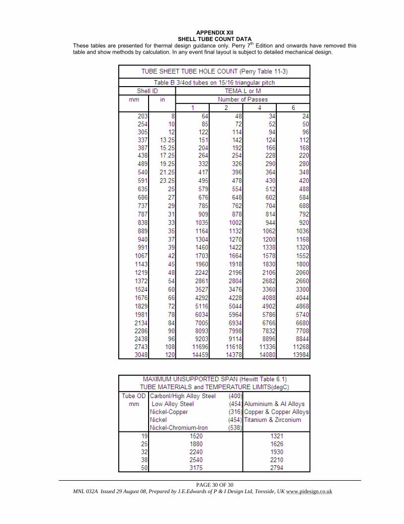
APPENDIX XII SHELL TUBE COUNT DATA
These tables are presented for thermal design guidance only. Perry 7th Edition and onwards have removed this table and show methods by calculation. In any event final layout is subject to detailed mechanical design.
Recommended