26850A004 REV04091
E54-30-H/D Part No. 26866F020
E70-23V-H/D Part No. 26866F120
E80-20V-H/D Part No. 26866F320
E80-25-H/D Part No. 26866F124
E110-14-H/D Part No. 26866F220
E SeriesReciprocating Pump (Hydraulic Drive)Safety Instructions and Service Manual

26850A004 REV04092
Table of Contents
SPECIFICATIONS ............................................................................................................................. 3DIMENSIONS – HYDRAULIC MOTOR MOUNT ............................................................................... 4DIMENSIONS: COMPLETE PUMP ................................................................................................... 5STARTING THE PUMP ...................................................................................................................... 5
SUGGESTED MAINTENANCE SCHEDULE ..................................................................................... 5LUBRICATION .................................................................................................................................... 5ADDITIVES FOR CRANKCASE OIL .................................................................................................. 5
SERVICING THE PUMP: REMOVING P ISTON ..................................................................................................................... 6 INSTALLING THE CUP ............................................................................................................... 6
REMOVING THE CYLINDERS ..................................................................................................... 6 INSTALLATION .............................................................................................................................. 6 REMOVING THE SEATS: Wing Guided Valves ............................................................................. 7 REPLACEMENT OF VALVES ....................................................................................................... 7 REPLACING PISTON ROD SEALS .............................................................................................. 7 REMOVING CRANKSHAFT AND PINION SHAFT ....................................................................... 8 REPLACING PINION SHAFT & SHIMMING BEARINGS ............................................................. 8 REPLACING CRANKSHAFT & SHIMMING BEARINGS .............................................................. 9 RECONDITIONED CRANKSHAFTS ............................................................................................ 9 SERVICING CONNECTING LINKS .............................................................................................. 9 CROSSHEAD AND PISTON RODS............................................................................................ 10 RECOMMENDED TORQUE (Foot-pounds) ................................................................................ 10 VALVE LIFTE RS .......................................................................................................................... 11 SERVICE CHART & TROUBLESHOOTING ......................................................................... 12–14
CROSS-SECTIONAL VIEWS OF PUMPS: SIDE VIEW – E54-30-H/D, E70-23-H/D, E80-20-H/D, E110-14-H/D ........................................... 15 SIDE VIEW – E70-23V-H/D, E80-20V-H/D, E80-25-H/D ............................................................. 16 POWER-END ............................................................................................................................. 17 PARTS LIST ................................................................................................................................ 18

26850A004 REV04093
SPECIFICATIONS
GPM 1800 PSI 2100 PSI 2400 PSI 2700 PSI 3000 PSILPM 124 BAR 145 BAR 165 BAR 186 BAR 207 BAR
30 37 43 49 55 62113 28 32 36 41 4636 44 52 59 66 74136 33 39 44 49 5542 51 60 59 79 86158 38 45 51 59 6448 59 69 79 89 98181 44 51 59 66 7354 66 79 89 100 111204 49 59 66 75 83
E-54-30
1417
1620
1823
Horsepower/Kilowatts Required For:
RPM
1012
1215
GPM 1900 PSI 2000 PSI 2100 PSI 2200 PSI 2300 PSILPM 131 BAR 138 BAR 145 BAR 152 BAR 159 BAR30 39 41 43 45 47113 29 31 32 34 3540 52 55 57 60 63151 39 41 42 45 4750 65 69 72 75 80189 48 51 54 56 6060 78 82 86 90 95227 58 61 64 67 7170 91 96 100 105 110265 68 72 75 78 82
Horsepower/Kilowatts Required For:
RPM
914
1143
E70-23V
1371
1600
1828
TRIPLEX PUMP MODELS
E54-30-H/D E70-23V-H/D E80-20V-H/D E80-25-H/D E110-14-H/D
RATED MAX CAPACITY (GPM) 54 70 80 80 110
PINION SHAFT RPM @ MAX. CAPACITY 1823 1807 1828 1828 1817
PRESSURE RATING (PSI) 3000 2300 2000 2500 1400
CYLINDER BORE DIA. (INCHES) 1.750 2.000 2.125 2.125 2.500
PISTON STROKE LENGTH (INCHES) 3.75
GEAR REDUCTION RATIO 3.95 to 1
TEMPERATURE RATING, MAX. 160°F
SUCTION SIZE (INCHES) NOMINAL 3 NPT
DISCHARGE SIZE (INCHES) NOMINAL 1-1/4 NPT
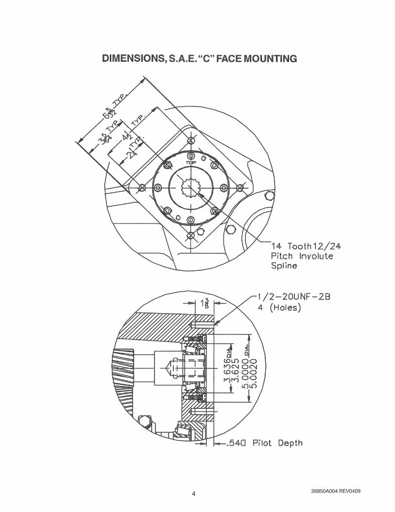
HYDRAULIC MOTOR MOUNTING SPEC. S.A.E. “C” (See page 4 for details)
PINION SHAFT INTERNAL SPLINE 14 TOOTH 12/24 (See page 4 for details)
WEIGHT (Lbs.) 525
FLUID-END CASTING MATERIAL DUCTILE IRON
VALVE MATERIAL 17-4 PH with POLYURETHANE INSERT
VALVE SPRING MATERIAL STAINLESS STEEL
CYLINDER MATERIAL STAINLESS STEEL/CERAMIC OXIDE COATING
PISTON CUPS MATERIAL PROPRIETARY HSN/ARAMID FIBER
GPMLPM
Horsepower/Kilowatts Required For:
RPM 1200 PSI 1400 PSI 1600 PSI 1800 PSI 2000 PSI 2200 PSI 2400 PSI 2500 PSI
83 BAR 97 BAR 110 BAR 124 BAR 138 BAR 152 BAR 165 BAR 172 BAR
40914
33 38 44 49 55 60 66 69
151 25 29 33 37 41 45 49 51
501143
41 48 55 62 69 75 82 86
189 31 36 41 46 51 56 61 64
601371
49 58 66 74 82 91 99 103
227 37 43 49 55 61 68 74 77
701600
58 67 77 86 96 106 115 120
265 43 50 57 64 72 79 86 90
801828
66 77 88 99 110 121 132 137
30 49 57 66 74 82 90 98 102
GPMLPM
Horsepower/Kilowatts Required For:
RPM 800 PSI 1000 PSI 1200 PSI 1400 PSI
55 BAR 69 BAR 83 BAR 97 BAR
701157
38 48 58 67
265 28 36 43 50
801322
44 55 66 77
302 33 41 49 57
901487
49 62 74 86
340 37 46 55 64
1001652
55 69 82 96
378 41 51 61 72
1101817
60 75 90 106
416 45 56 67 79
NOTE: Flow (GPM/LPM) based on 100% volumetric efficiency. Horsepower and kilowatts required are based on 85% overall efficiency.
Horsepower requirements are at Myers pump input shaft. The efficiency of the hydraulic pump, hydraulic motor, etc. must be considered to determine horsepower required to drive complete system.
E80-20V-H/D / E80-25-H/D
E54-23-H/D
SPECIFICATIONS
E110-14-H/D
E70-23V-H/D
SPECIFICATIONS
GPM 1800 PSI 2100 PSI 2400 PSI 2700 PSI 3000 PSILPM 124 BAR 145 BAR 165 BAR 186 BAR 207 BAR
30 37 43 49 55 62113 28 32 36 41 4636 44 52 59 66 74136 33 39 44 49 5542 51 60 59 79 86158 38 45 51 59 6448 59 69 79 89 98181 44 51 59 66 7354 66 79 89 100 111204 49 59 66 75 83
E-54-30
1417
1620
1823
Horsepower/Kilowatts Required For:
RPM
1012
1215
GPM 1900 PSI 2000 PSI 2100 PSI 2200 PSI 2300 PSILPM 131 BAR 138 BAR 145 BAR 152 BAR 159 BAR30 39 41 43 45 47113 29 31 32 34 3540 52 55 57 60 63151 39 41 42 45 4750 65 69 72 75 80189 48 51 54 56 6060 78 82 86 90 95227 58 61 64 67 7170 91 96 100 105 110265 68 72 75 78 82
Horsepower/Kilowatts Required For:
RPM
914
1143
E70-23V
1371
1600
1828
26850A004 REV04094

26850A004 REV04095

26850A004 REV04096

26850A004 REV04097

26850A004 REV04098

26850A004 REV04099
26850A004 REV040910
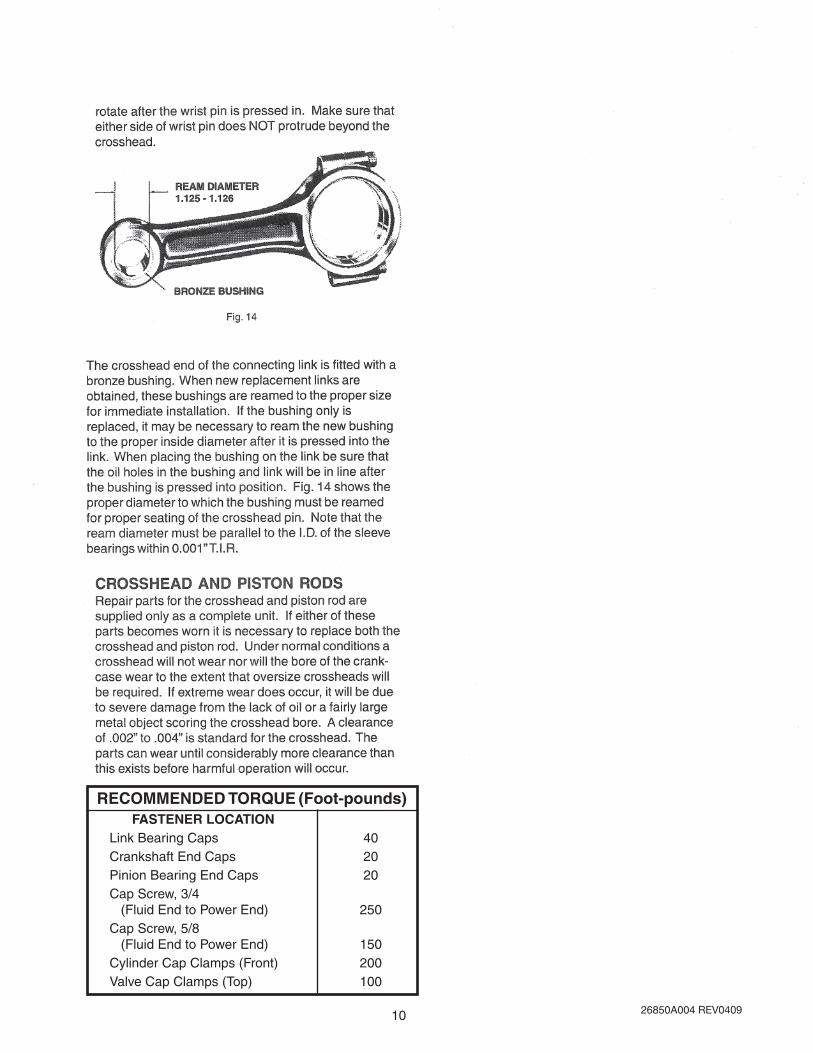
RECOMMENDED TORQUE (Foot-pounds) FASTENER LOCATION Link Bearing Caps 40 Crankshaft End Caps 20 Pinion Bearing End Caps 20 Cap Screw, 3/4 (Fluid End to Power End) 250 Cap Screw, 5/8 (Fluid End to Power End) 150 Cylinder Cap Clamps (Front) 200 Valve Cap Clamps (Top) 100

26850A004 REV040911

26850A004 REV040912

26850A004 REV040913

26850A004 REV040914

26850A004 REV040915
E54
-30-
H/D
, E70
-23-
H/D
, E80
-20-
H/D
, E11
0-14
-H/D

26850A004 REV040916
E70
-23V
-H/D
, E80
-20V
-H/D
, E80
-25-
H/D

26850A004 REV040917

26850A004 REV040918
1 Case, gear 1 04625E100E
2 Shim, plastic, pink, .015" 6 05068A016
3 Shim, plastic, green, .003" 6 05068A018
4 O-ring, 5-1/8" O.D. 2 05876A098
5 Washer, seal 18 14946A003
6 Screw, cap 3/8"-16 UNC x 1" 18 19101A013
7 Cap, bearing, crankshaft 2 04624B004
8 Cup, bearing, crankshaft 2 05675A013
9 Cone, bearing, crankshaft 2 05674A018
10 Crankshaft, w/75 teeth gear
(All E series except E80-25) 1 20355C044
E80-25 1 20355C022
12 Oil Seal, 2" 1 05710A046
13 Cap, open, pinion 1 04563A010
14 Cup, bearing, pinion 2 05675A019
15 Cone, bearing, pinion 2 05674A020
16 Shim, .015" Thk. 4 05863A023
17 Shim, .003" Thk. 4 05863A024
18 Shaft, pinion, 19 Teeth 1 20164B040
19 Cover 1 26588B000
20 Screw, Hex hd., 1/2"-20 UNF x 3/4" 4 19103A054
21 Screw, Cap, 5/16"-24 UNF x 1" 16 06106A048
22 Crosshead Assembly
(All E series except E80-25) 3 06211B042
E80-25 3 06211B044
23 Link, with bushing & screws 3 17042C002
Bushing, wrist pin 3 B01619A000K
Washer, lock 6 05454A004
Screw, cap 6 19103A016
24 Wrist pin 3 M01525A001K
25 Bearing, two halves 3 15245A101K
26 Plug, drain, magnetic, 3/4-14 1 17481A002
27 Gasket, lid, special shape 1 06201C000
28 Screw, cap 5/16"-18 x 7/8" St. 8 19100A033
29 O-ring, oil gauge 1 110-000110-201
30 Gauge, oil & O-ring (Item 29) 1 17360A011K
31 Lid, gear case 1 04561B000
32 Nipple, special vent 1 17995A000
33 Cap, pipe 1 05737A002
34 Slinger, neoprene 3 05059A263
35 Screw, cap, hex, 5/8-11 UNC x 2 4 19105A008
36 Screw, skt. hd. 10-32 UNF x 1/2" 6 06106A034
37 Housing, oil seal 3 24959A000
38 Spring, seal retainer 3 M01643A000
39 Gasket, seal housing, 2.312 O.D. 3 05059A434
40 Gasket, Vellumoid, 3.50 O.D. 3 05059A058
41 Retainer, oil seal housing 3 24958A000
42 Oil Seal, U cup, Viton 6 22835A003
43 Screw, skt. hd. 3/4-10UNC x 2-1/2" 4 06106A038
44 Washer, lock, 3/4" 4 05454A003
45 Screw, drive, .133 x 5/16" 6 05160A004
49 Body, cylinder 1 18639F008
50 Lid, cylinder (Pony rod cover) 1 M01520A000
51 Clamp, lid 2 26842A000
52 Screw, mach. 1/4-20 UNC x 1/2" 2 148850001
53 O-ring, 1-1/4" O.D. 3 110-000024-218
54 Piston hub E54-23 3 7206-0390-00A
E70-23 3 7206-0393-00A
E80-20 3 7206-0396-00A
E110-14 3 7206-0358-00A
55 Liner, cyl. E54-30 1.750 I.D. 3 26849A000
E70-23 2.000 I.D. 3 20851A001
E80-20 2.125 I.D. 3 20851A004
E110-14 2.500 I.D. 3 M01512A003
56 Piston, cup, E54-30 1.750" O.D. 3 7206-0389-00A
E70-23 2.000 O.D. 3 7206-0392-00A
E80-20 2.125 O.D. 3 7206-0395-00A
Flat Back E110-14 2.500 O.D. 3 7203-0617-00A
57 Retainer, piston E54-30 3 7206-0391-00A
E70-23 3 7206-0394-00A
E80-20 3 7206-0397-00A
E110-14 3 7206-0389-00A
57A Washer, lock 3 06107A013
58 Screw, cap, .551" M-14 metric 3 16654A006
59 O-ring, 2-15/16" O.D.,cyl. liner 3 05876A095
60 Seal, ring, valve cap 3 26862A001
61 Cap, valve 3 26848A000
62 Clamp, 5/8" stud, valve cap 3 20848A000
63 Stud, 5/8-11 UNC x 3-5/16 Lg. 6 05659A560
64 Nut, hex 5/8"-11 UNC 6 19109A046
65 Cage, valve 6 7203-0544-00B
66 Spring, valve 6 7206-0302-00A
67 Valve, guide 6 7203-0542-00A
68 Insert, valve, polyurethane 6 7203-0546-00A
69 O-ring, valve, 2.004 O.D. 6 110-000032-201
70 Seat, valve 6 7203-0543-00B
71 Seal, ring, cylinder cap 3 7202-0041-00A
72 Cap, cylinder 3 26805A000
74 Clamp, 7/8" stud, cylinder cap 3 20856A000
75 Stud, 7/8"-14 UNF x 4-1/2" 6 05659A089
76 Nut, hex, 7/8-14 UNF 6 19109A072
77 Plug, pipe, 1-1/4" NPT 1 05022A041
80 Plug, pipe, 3" NPT 2 03210A000
81 Plug, pipe, 1" NPT 3 05022A043
82 Plug, pipe, 1/2" NPT 3 05022A015
87 Spring 3 20853A000
88 Packing E70-23V 3 18922A000
E80-20V, E80-25 3 18922A004
89 Pressure Ring E70-23V 3 18921A000
E80-20V, E80-25 3 20854A000
90 Retainer, spring 3 20852A003
91 Follower E70-23V 3 18932A002
E80-20V, E80-25 3 20855A000
92 Piston body E70-23V 3 18924A004
E80-20V, E80-25 3 20850A011
Ref. Name & Description Qty. Part No. Ref. Name & Description Qty. Part No.
“E” SERIES – HYDRAULIC DRIVE – PARTS LIST
Note: Bold type indicates “normal” wear items or items replaced when rebuilding a reciprocating pump.

26850A004 REV040919
NOTES

26850A004 REV040920
NOTES

26850A004 REV040921
NOTES

26850A004 REV040922
1101 Myers Parkway, Ashland, Ohio 44805-1969419/289-1144 • FAX 419/289-6658 • TLX: 948-7443
MYERSLIMITED WARRANTY
F. E. MYERS warrants that its products are free from defects in material and workmanship for a period of twelve (12) months from the date of purchase or eighteen (18) months from the date of manufacture, whichever occurs first.
During the warranty period and subject to the conditions hereinafter set forth, MYERS, will repair or replace to the original user or consumer parts which prove defective due to defective materials or workmanship of MYERS. Contact the nearest authorized MYERS distributor, MYERS authorized service center or MYERS for warranty service. At all times, MYERS shall have and possess the sole right and option to determine whether to repair or replace defective equipment, parts or components.
Start up reports and electrical system schematics may be required to support warranty claims. Warranty is effective only if MYERS supplied or authorized control panels are used, where applicable. All dual seal pumps must have seal failure and heat sensors attached, functional and monitored for the warranty to be in effect. If a seal failure should occur, MYERS will only cover the lower seal and labor thereof. If the heat sensor and seal fail sensor is not attached and functional, the warranty is void.
LABOR, ETC. COSTS: MYERS shall in NO EVENT be responsible or liable for the cost of field labor, removal and/or reinstallation charges of any MYERS product, part or component thereof, or the expense of freight.
THIS WARRANTY WILL NOT APPLY: (a) to defects or malfunctions resulting from failure to properly install, operate or maintain the unit in accordance with printed instructions provided; (b) to failures resulting from abuse, accident or negligence; (c) to normal maintenance services and the parts used in connection with such service; (d) to units which are not installed in accordance with applicable local codes, ordinances and good trade practices; or (e) if the unit is moved from its original installation location; (f) unit is used for purposes other than for what it was designed and manufactured; (g) to any unit which has been repaired or altered by anyone other than MYERS, a MYERS distributor or a MYERS authorized service center and (h) to any unit which has been repaired using non factory specified parts/OEM parts.
RETURN OR REPLACED COMPONENTS: any item to be replaced under this Warranty must be returned to MYERS in Ashland, Ohio, or such other place as MYERS may designate, freight prepaid.
PRODUCT IMPROVEMENTS: MYERS reserves the right to change or improve its products or any portions thereof without being obligated to provide such a change or improvement for units sold and/or shipped prior to such a change or improvement.
WARRANTY EXCLUSIONS: MYERS MAKES NO EXPRESS OR IMPLIED WARRANTIES WHICH EXTEND BEYOND THE DESCRIPTION ON THE FACE HEREOF. MYERS SPECIFICALLY DISCLAIMS THE IMPLIED WARRANTIES OF MERCHANTABILITY AND FITNESS FOR ANY PARTICULAR PURPOSE.
Some states do not permit some or all of the above warranty limitations and, therefore, such limitations may not apply to you. No warranties or representations at any time made by any representatives of Myers shall vary or expand the provision hereof.
LIABILITY LIMITATION: IN NO EVENT SHALL MYERS BE LIABLE OR RESPONSIBLE FOR CONSEQUENTIAL, INCIDENTAL OR SPECIAL DAMAGES RESULTING FROM OR RELATED IN ANY MANNER TO ANY MYERS PRODUCT OR PARTS THEREOF. PERSONAL INJURY AND/OR PROPERTY DAMAGE MAY RESULT FROM IMPROPER INSTALLATION. MYERS DISCLAIMS ALL LIABILITY, INCLUDING LIABILITY UNDER THIS WARRANTY. FOR PROPER INSTALLATION MYERS RECOMMENDS INSTALLATION BY PROFESSIONALS.
Some states do not allow the exclusion or limitation of incidental or consequential damages, so the above limitation or exclusion may not apply to you.
This Warranty gives you specific legal rights and you may also have other rights which vary from state to state.
In the absence of suitable proof of this purchase date, the effective date of this warranty will be based upon the date of manufacture.
Direct all notices, etc. to:Service Department, F.E. MYERS, A Pentair Company, 1101 Myers Parkway, Ashland, Ohio 44805.

26850A004 REV040923

26850A004 REV040924
START-UP REPORTDistributor______________________________________________________Order #: _________________
Installing Contractor: _____________________________________ Phone: _________________________
Sales Contact: __________________________________________ Phone: _________________________
Customer & Location _____________________________________________________________________
1. SYSTEM INFORMATIONA. Size of wet well: __________________________________ Manufacturer:_____________________B. Discharge from bottom of basin: ___________________ Location:__________________________C. Inlet from bottom of basin:________________________ Location: __________________________D. Type of check valves: ______________________________________________________________E. Type of piping ____________________________________________________________________F. Does system have suction and discharge gauges? _______________________________________G. Pressure reading? Suction_____________________ Discharge _________________________H. Liquid being pumped:____________________ Temperature: __________ % of solid: __________I. Sketch or photograph of system attached? _____________________________________________J. Any additional comments on system: ____________________________________________________________________________________________________________________________________
2. ELECTRICAL INFORMATIONA. Control panel part #:__________________________ Panel rated amps: ___________________
Manufacturer ___________________________ Voltage: __________ Phase: _____________B. Heater size: _____________________________________________________________________C. Location of panel to wet well: ________________________________________________________D. Incoming line voltage: _________________________ Actual? _____________________________E. Voltage to pumps ____________________________ Actual? _____________________________F. Type of junction box: _____________________________ Manufacturer:_______________________G. Are floats installed in wet well? _______________________________________________________H. Are floats set to engineer’s spec? ____________________________________________________I. Are floats wired for proper sequencing? ________________________________________________J. Any additional comments on electrical: __________________________________________________________________________________________________________________________________
3. PUMP INFORMATIONA. Type of pump:______________________________________ Serial # ______________________B. Voltage:_____________ Phase:_____________ RPM:_____________ Amps: ___________C. Impeller size: ______________ C.O.S. TDH:________________ GPM: ___________________D. Voltage supplied from panel:___________________ Actual?: _____________________________E. Actual amperage (all phases): _____________ amps _____________amps _____________ampsF. Have you checked pump rotation? ____________________________________________________G. Any additional comments on pumps: ____________________________________________________________________________________________________________________________________
Acknowledge that all information is accurate and proper procedures have been followed:
Customer Signature:__________________________________________________ Date ___________
Start-up Technician:__________________________________________________ Date __________
Send to: Warranty Department, 740 E. Ninth Street, Ashland, OH 44805, Fax: 419-207-3344,or e-mail to: [email protected]
We will make this a permanent part of our file on this order.
cut along d
otted line
Recommended