438
CAD drawing data catalogis available.
ACTUATORS GENERAL CATALOG
DYNA CYLINDERSCONTENTS
Before use, be sure to read the “Safety Precautions” on p. 57.Caution
DYNA
CYL
INDE
RS
Features 439Handling Instructions and Precautions 441Air Flow Rate and Air Consumption, and Cylinder Thrust 445Standard Cylinders 446Non-rotating Cylinders 454Double Rod Cylinders 462Non-rotating Double Rod Cylinders 468Tandem Cylinders 474Dual Stroke Cylinders 482Stroke Adjusting Cylinders 488Low Hydraulic Cylinders 498Valpack Cylinders 506End Keep Cylinders 514Cylinders with Brakes 518Sensor Switches 532Knuckles and Bellows 537
438_453ダイナシリンダ_ENG 07.8.25 11:05 AM ページ438

439
The DYNA cylinders, compact and lightweight mid-sized
actuators compatible with ISO standards, offer a wide range
of configurations and mounting types to meet various
application requirements in a flexible manner.
Moreover, the use of a new type of cushion needle and
floating seal have made these products user-friendlier.
Standard cylinders Non-rotating cylinders Double rod cylinders Non-rotating double rod cylinders
Tandem cylinders Dual stroke cylinders Push side stroke adjusting cylinders Pull side stroke adjusting cylinders
Low hydraulic cylinders Valpack cylinders End keep cylinders Cylinders with brakes
Basic type Foot mounting type Axial foot mounting type Rod side flange mounting type
Head side flange mounting typeClevis
mounting type Pivot mounting type With supporting brackets
Sensor switches Knuckles Cylinders with bellows
PrProduct Line Upoduct Line Up
Mounting typeMounting type
AccessoryAccessory
DYNA CYLINDERS Ultra-reliable, high-function tie-rod cylinder
With supporting bracket
Trunnion type
438_453ダイナシリンダ_ENG 07.8.25 11:05 AM ページ439

440
The series configuration together with itsversatile functionality and specificationsoffers the best match for various mechanicaldevices.
Using a new type of cushion needle that is completelyembedded in the cylinder body offers fine adjustment
for better performance.
Improved cushioning is gained by utilizingfloating seal in the cushion section.
New release of cylinders with brakes. Exhaustingcompressed air pushes a brake shoe against thepiston rod thereby stopping the cylinder.
Oil impregnated sintered copper alloy inbushings enables stable operation and longerlife.
Standard cylinder(φ32 [1.260]~φ125 [4.921])
Non-rotating cylinder(φ40 [1.575]~φ100 [3.940])
Double rod cylinder(φ32 [1.260]~φ125 [4.921])
Non-rotating double rod cylinder(φ40 [1.575]~φ100 [3.940])
Tandem cylinder(φ40 [1.575]~φ100 [3.940])
Dual stroke cylinder(φ40 [1.575]~φ100 [3.940])
Push side stroke adjusting cylinder(φ40 [1.575]~φ100 [3.940])
Pull side stroke adjusting cylinder(φ40 [1.575]~φ100 [3.940])
Low hydraulic cylinder(φ32 [1.260]~φ100 [3.940])
Valpack cylinder(φ40 [1.575]~φ100 [3.940])
End keep cylinder(φ40 [1.575]~φ100 [3.940])
Cylinder with brake (φ40 [1.575]~φ100 [3.940])
Basic
type
Foot
mounti
ng ty
peAxia
l foot
mounti
ng ty
pe
Rod sid
e flan
ge m
ountin
g type
Head s
ide fla
nge m
ountin
g type
Clevis m
ounting
type (w
ith supp
orting br
acket)
Pivot m
ounti
ng ty
peTru
nnion
type (w
ith sup
porting
bracke
ts)
mm [in.]
Series configurations
Extensive variation offunctions New cushion needle
Improved cushioning
Safe self-lockingmechanism
Long life
Air flow
Snap ring
O-ring
Cushion needle
Brake shoe
Spring Brake piston
Steel ball
※Steel balls and a brakeshoe are secured inposition. Operating thebrake piston enablesactivation or release ofthe brake.
design in the smallest standard size for a mid-sized,
DYNA
CYL
INDE
RS
438_453ダイナシリンダ_ENG 07.8.25 11:06 AM ページ440

441
Use mounting screws which are supplied with the bracket to assemble themounting bracket. Use an Allen wrench to tighten the mounting screws evenly.When 4 screws are used, tighten diagonally from each corner. The tighteningtorque is shown below.
HandlingGeneral precautions
Assembly of mounting bracket
For disassembly, insert an Allen wrench to loosen the tie rod nut, and removethe cover.For assembly, screw in the tie rod nut with the hexagon socket facing outward.Evenly tighten diagonally from each corner. The tightening torque is shownbelow.
Assembly and disassembly
Head cover
Use hexagon socket tie rod nuts on both sides for only 32φ
Head cover
Hexagon socket tie rod nut
Hexagon socket tie rod nut
Tie rod nut with knurl
Tightening torque
4.81N·m [3.55ft·lbf]
12.0N·m [8.85ft·lbf]
24.0N·m [17.7ft·lbf]
42.2N·m [31.1ft·lbf]
〈Tightening torque of mounting brackets and tie rod nuts〉
Tie rod nut
6 [0.236]
6 [0.236]
8 [0.315]
10 [0.394]
12 [0.472]
Mounting bracket
4 [0.157]
4 [0.157]
5 [0.197]
6 [0.236]
8 [0.315]
mm [in.]Width across flats of hexagon socket
φ40 [1.575in.]~φ125 [4.921in.]
φ32 [1.260in.]
Handling Instructions and Precautions
Bore size mm [in.]
32, 40, 50 [1.260, 1.575, 1.969]
63 [2.480]
80, 100 [3.150, 3.940]
125 [4.921]
Bore size
32 [1.260]
40, 50 [1.575, 1.969]
63 [2.480]
80, 100 [3.150, 3.940]
125 [4.921]
Always thoroughly blow off (use compressed air) the tubingbefore connecting it to the DYNA cylinder. Entering chips,sealing tape, rust, etc., generated during piping work could resultin air leaks or other defective operation.
If using in locations subject to dripping water, dripping oil, etc.,or to large amounts of dust, use a cover to protect the unit.
1. Use air for the media. For the use of any other media, consultus.
2. Air used for the DYNA cylinder should be clean air thatcontains no deteriorated compressor oil, water, dust, etc.Install an air filter (filtration of a minimum 40 µm) near thecylinder or valve to remove collected liquid or dust. In addition,drain the air filter periodically.
This equipment can be used without lubrication. If lubrication isrequired, use Turbine Oil Class 1 (ISO VG32) or lithium soap-based grease No.2 or equivalent.
Piping
Lubrication
Atmosphere
Media
438_453ダイナシリンダ_ENG 07.8.25 11:06 AM ページ441

442
1. For control of the DYNA end keep cylinders, we recommend the useof 2-position, 4-, 5-port valves. Avoid the use of control circuit of ABRconnections (exhaust centers) with 3-position valves that exhaust airfrom 2 ports.
2. Always use meter-out control for speed control. Meter-in control mayresult in failure of the locking mechanism to release.
3. Always set the air pressure to 0.15MPa [22psi.] or more.
Cautions: 1. It is dangerous to supply air to a connection port on a side witha locking mechanism while the cylinder has already beenexhausted, because the piston rod may suddenly extend (orretract). In addition, since the lock piston could also causegalling of the lock piston and piston rod, resulting in defectiveoperation. Always supply air to the connection port on theopposite side of the locking mechanism to ensure applyingback pressure.
2. When restarting operations after air has been exhausted fromthe cylinder due to completion of operations or to anemergency stop, always start by supplying air to a connectionport on the opposite side of the locking mechanism.
3. Connect the valve port A (NC) to the connection port on theside with the locking mechanism.
Control circuit for the end keep cylinderManual operation of end keep cylinderlocking mechanism
While the locking mechanism is normally released automatically throughcylinder operations, it can also be released manually. For manual release,insert an M4×0.7 screw that has 30mm [1.18in.] screw length into the manualoverride opening, thread it in about 3 turns into the internal lock piston, andthen pull up the screw. To maintain the manual override for adjustment, etc.,thread the locknut onto the screw and, with the locking mechanism in areleased state, tighten the locknut against the cylinder.
Cautions: 1. It is dangerous to release the lock when load (weight) is presenton the piston rod, because it may cause the unintended pistonrod’s extension (or retraction). In this case, always supply air tothe connection port opposite the one adjacent to the lockingmechanism before releasing the locking mechanism.
2. If the locking mechanism cannot easily be released even withmanual override, it could be the result of galling of the lockpiston and piston rod. In this case, supply air to the connectionport opposite the one adjacent to the locking mechanism beforereleasing the locking mechanism.
3. Because water, oil, dust, etc., intruding through the manualoverride opening may be a cause of defective locks or othererratic operation. If using in locations subject to dripping water,dripping oil, etc., or large amounts of dust, use a cover toprotect the unit.
4. If the circuit cannot maintain exhaust pressure at 0.03MPa[4.4psi.] or less due to using a manifold valve, use individualvalve for operations.
Handling Instructions and Precautions
Machine screw M4×0.7(length appr. 30mm[1.18in.])
M5×0.8
φ7
12
187
4 2
The dedicated muffler can be mounted on themanual override opening.Dedicated muffler model SA-5 (mm)
Dedicated muffler
DYNA
CYL
INDE
RS
438_453ダイナシリンダ_ENG 07.8.25 11:06 AM ページ442

443
The cylinder with brake uses a mechanism that consists of steel balls contacting a incline and it
receives components of a spring force, then it transmits the force via a brake shoe to apply to the
piston rod.
A supply of compressed air from the brake
releasing port causes the brake piston
including the taper ring, to retract thereby
freeing the steel balls from the taper ring,
which releases the brake and lets the piston
rod freely slide.
When the brake is released
Exhausting compressed air from the brake
releasing port causes the spring to press
against the brake piston, transmitting
components of spring force via the taper ring
to the steel balls, which then works via the
brake shoe to transmit a perpendicular force
to the piston rod and to apply friction force to
the brake.
When the brake is applied
Operating principle
1. In the cylinder with brake, the brake piston in the single brake type is secured in place with 2
hexagon socket screws, and in the double brake type with 4 such screws, with the brake set
in a released state at shipping.
When piping and installation is completed, or when performing operation checks, first supply
at least 0.35MPa [51psi.] (0.4MPa [58psi.] for bore size of φ50 [1.969in.]) of air to the brake
release port, and remove the screws. Then exhausting the compressed air enables the piston
rod to be held. While the unit could be operated with the screws removed, it is better for
prevention of entering dust to use screws with nuts to secure it in place by inserting 2 or 3
thread ridges into the cylinder.
At this time, do not excessively tighten the screws as they could interfere with the brake
piston, by re-locking it in place, or by constricting its movements.
2. Poor centering of the Cylinder with Brake may damage the seal or hasten wear on the brake
shoe.
As poor centering could also result in inaccuracy of the stopping position, use of a cylinder
joint is recommended.
Precautions for installation
Handling Instructions and Precautions
Mounting and piping (for cylinder with brake)
Brake piston
Spring
Brake releasing port
Taper ring
Steel ballBrake shoe
When the brake is released
When the brake is applied
Brake lock release screw
Single brake : 2 placesDouble brake: 4 places
During operation, loosen the brake lockrelease screw, and set so that it does notbump against the brake piston.
Brake lock release screw
(Hexagon socket screw)
Brake piston
438_453ダイナシリンダ_ENG 07.8.25 11:06 AM ページ443
444
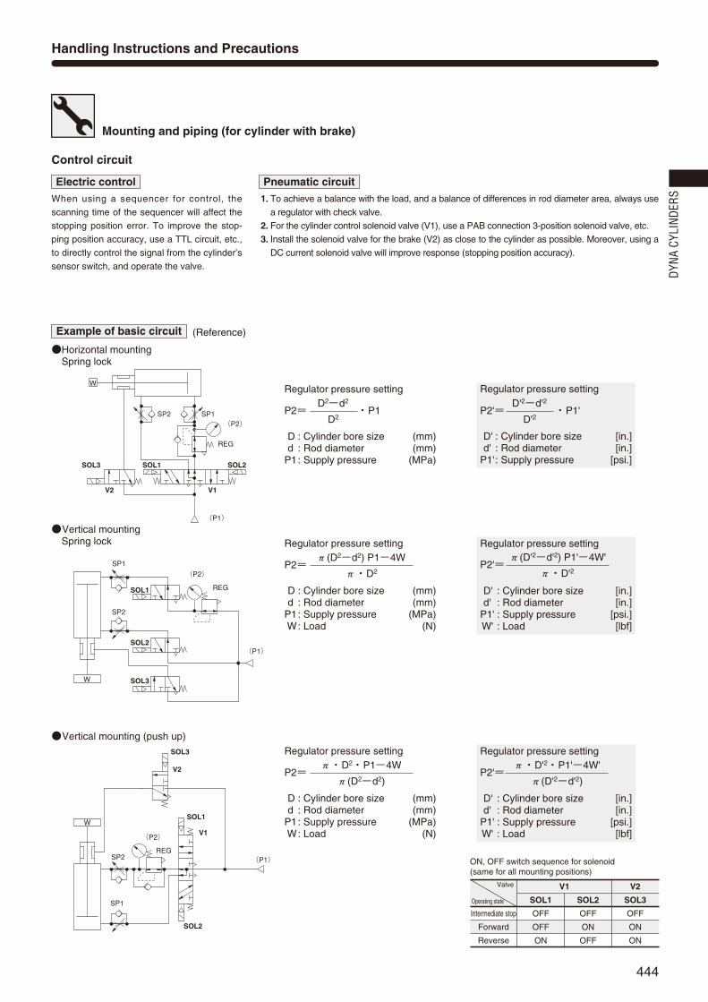
Valve
Operating state
Intermediate stop
Forward
Reverse
SOL1
OFF
OFF
ON
V1
SOL2
OFF
ON
OFF
SOL3
OFF
ON
ON
V2
ON, OFF switch sequence for solenoid(same for all mounting positions)
When using a sequencer for control, the
scanning time of the sequencer will affect the
stopping position error. To improve the stop-
ping position accuracy, use a TTL circuit, etc.,
to directly control the signal from the cylinder’s
sensor switch, and operate the valve.
1. To achieve a balance with the load, and a balance of differences in rod diameter area, always use
a regulator with check valve.
2. For the cylinder control solenoid valve (V1), use a PAB connection 3-position solenoid valve, etc.
3. Install the solenoid valve for the brake (V2) as close to the cylinder as possible. Moreover, using a
DC current solenoid valve will improve response (stopping position accuracy).
Control circuit
Handling Instructions and Precautions
Electric control Pneumatic circuit
Example of basic circuit (Reference)
Horizontal mountingSpring lock
Vertical mountingSpring lock
Vertical mounting (push up)
SP2 SP1(P2)
REG
SOL2
V1
(P1)
SOL1
V2
SOL3
W
SP1(P2)
REG
SOL2
SP2
SOL3
SOL1
(P1)
W
W
SP1
SP2REG
(P2)
SOL2
V1
V2
SOL1
SOL3
(P1)
Mounting and piping (for cylinder with brake)
Regulator pressure setting
D : Cylinder bore size (mm)d : Rod diameter (mm)
P1: Supply pressure (MPa)
P2= ・P1D2-d2
D2
Regulator pressure setting
D' : Cylinder bore size [in.]d' : Rod diameter [in.]
P1': Supply pressure [psi.]
P2'= ・P1'D'2-d'2
D'2
Regulator pressure setting
D : Cylinder bore size (mm)d : Rod diameter (mm)
P1: Supply pressure (MPa)W: Load (N)
P2=π(D2-d2) P1-4W
π・D2
Regulator pressure setting
D' : Cylinder bore size [in.]d' : Rod diameter [in.]
P1' : Supply pressure [psi.]W' : Load [lbf]
P2'=π(D'2-d'2) P1'-4W'
π・D'2
Regulator pressure setting
D : Cylinder bore size (mm)d : Rod diameter (mm)
P1: Supply pressure (MPa)W: Load (N)
P2=π・D2・P1-4W
π(D2-d2)
Regulator pressure setting
D' : Cylinder bore size [in.]d' : Rod diameter [in.]
P1' : Supply pressure [psi.]W' : Load [lbf]
P2'=π・D'2・P1'-4W'
π(D'2-d'2)
DYNA
CYL
INDE
RS
438_453ダイナシリンダ_ENG 07.8.25 11:06 AM ページ444

445
N [lbf.]
12 [0.472]
16 [0.630]
20 [0.787]
20 [0.787]
25 [0.984]
30 [1.181]
35 [1.378]
Push side
Pull side
Push side
Pull side
Push side
Pull side
Push side
Pull side
Push side
Pull side
Push side
Pull side
Push side
Pull side
804 [1.246]
690 [1.070]
1256 [1.947]
1055 [1.635]
1963 [3.043]
1649 [2.556]
3117 [4.831]
2803 [4.345]
5026 [7.790]
4536 [7.031]
7853 [12.17]
7147 [11.08]
12271 [19.02]
11310 [17.53]
80 [18.0]
69 [15.5]
126 [28.3]
106 [23.8]
196 [44.1]
165 [37.1]
312 [70.1]
280 [62.9]
503 [113]
454 [102]
785 [176]
715 [161]
1227 [276]
1131 [254]
161 [36.2]
138 [31.0]
251 [56.4]
211 [47.4]
393 [88.3]
330 [74.2]
623 [140]
561 [126]
1005 [226]
907 [204]
1571 [353]
1429 [321]
2454 [552]
2262 [508]
241 [54.2]
207 [46.5]
377 [84.7]
317 [71.3]
589 [132]
495 [111]
935 [210]
841 [189]
1508 [339]
1361 [306]
2356 [530]
2144 [482]
3681 [827]
3393 [763]
322 [72.4]
276 [62.0]
502 [113]
422 [94.9]
785 [176]
660 [148]
1247 [280]
1121 [252]
2010 [452]
1814 [408]
3141 [706]
2859 [643]
4908 [1103]
4524 [1017]
402 [90.4]
345 [77.6]
628 [141]
528 [119]
982 [221]
825 [185]
1559 [350]
1402 [315]
2513 [565]
2268 [510]
3927 [883]
3574 [803]
6136 [1379]
5655 [1251]
482 [108]
414 [93.1]
754 [169]
633 [142]
1178 [265]
989 [222]
1870 [420]
1682 [378]
3016 [678]
2722 [612]
4712 [1059]
4288 [964]
7363 [1655]
6786 [1525]
563 [127]
483 [109]
879 [198]
739 [166]
1374 [309]
1154 [259]
2182 [491]
1962 [380]
3518 [791]
3175 [714]
5497 [1236]
5003 [1125]
8590 [1931]
7917 [1780]
643 [145]
552 [124]
1005 [226]
844 [190]
1570 [353]
1319 [297]
2494 [561]
2242 [504]
4021 [904]
3629 [816]
6282 [1412]
5718 [1285]
9817 [2207]
9048 [2034]
724 [163]
621 [140]
1130 [254]
950 [214]
1767 [397]
1484 [334]
2805 [631]
2523 [567]
4523 [1017]
4082 [918]
7068 [1589]
6432 [1446]
11044 [2483]
10179 [2288]
804 [181]
690 [155]
1256 [282]
1055 [237]
1963 [441]
1649 [371]
3117 [701]
2803 [630]
5026 [1130]
4536 [1020]
7853 [1765]
7147 [1607]
12271 [2759]
11310 [2542]
Air pressure MPa [psi.]
0.1 [15] 0.2 [29] 0.3 [44] 0.4 [58] 0.5 [73] 0.6 [87] 0.7 [102] 0.8 [116] 0.9 [131] 1 [145]Bore sizemm [in.]
Rod diametermm [in.]
OperationPressure area
mm2 [in2]
cm3 [in.3]/Reciprocation (ANR)Air consumption for each 1mm [0.0394in.] stroke
Bore sizemm [in.]
Air pressure MPa [psi.]
0.1 [15]
3.20 [0.1953]
4.99 [0.3045]
7.80 [0.4760]
12.39 [0.7561]
19.98 [1.2193]
31.21 [1.9046]
48.77 [2.9761]
4.78 [0.2917]
7.48 [0.4565]
11.68 [0.7128]
18.54 [1.1314]
29.90 [1.8246]
46.72 [2.8510]
73.00 [4.4548]
6.37 [0.3887]
9.96 [0.6078]
15.56 [0.9495]
24.70 [1.5073]
39.83 [2.4306]
62.23 [3.7975]
97.23 [5.9334]
7.96 [0.4858]
12.44 [0.7591]
19.43 [1.1857]
30.85 [1.8826]
49.75 [3.0359]
77.73 [4.7434]
121.46 [7.4120]
9.55 [0.5828]
14.92 [0.9105]
23.31 [1.4225]
37.01 [2.2585]
59.67 [3.6413]
93.24 [5.6899]
145.69 [8.8906]
11.14 [0.6798]
17.40 [1.0618]
27.19 [1.6592]
43.16 [2.6338]
69.60 [4.2473]
108.75 [6.6364]
169.92 [10.369]
12.72 [0.7762]
19.88 [1.2132]
31.06 [1.8954]
49.32 [3.0097]
79.52 [4.8526]
124.25 [7.5822]
194.14 [11.847]
14.31 [0.8733]
22.36 [1.3645]
34.93 [2.1316]
55.46 [3.3844]
89.45 [5.4586]
139.76 [8.5287]
218.37 [13.326]
15.90 [0.9703]
24.84 [1.5158]
38.78 [2.3665]
61.57 [3.7572]
99.37 [6.0640]
155.27 [9.4752]
242.60 [14.804]
0.2 [29] 0.3 [44] 0.4 [58] 0.5 [73] 0.6 [87] 0.7 [102] 0.8 [116] 0.9 [131]
32 [1.260]
40 [1.575]
50 [1.969]
63 [2.480]
80 [3.150]
100 [3.940]
125 [4.921]
Cylinder Thrust
Air Flow Rate and Air Consumption
32 [1.260]
40 [1.575]
50 [1.969]
63 [2.480]
80 [3.150]
100 [3.940]
125 [4.921]
While the air cylinder’s air flow rate and air consumption canbe found through the following calculations, the quickreference chart to the right provides the answers moreconveniently.
Air flow rate Q1= ×L× × ×10-6
Air consumption Q2= ×L×2×n× ×10-6
Q1 : Required air flow rate for cylinder R/min(ANR)Q2 : Air consumption of cylinder R/min(ANR)D : Cylinder tube inner diameter mmL : Cylinder stroke mmt : Time required for cylinder to travel 1 stroke sn : Number of cylinder reciprocations per minute times/minP : Pressure MPa
πD2
460t
P+0.10130.1013
πD2
4P+0.1013
0.1013
Air flow rate Q1'= ×L'× × ×
Air consumption Q2'= ×L'×2×n× ×
Q1' : Required air flow rate for cylinder ft.3/min.(ANR)※Q2' : Air consumption of cylinder ft.3/min.(ANR)※D' : Cylinder tube inner diameter in.L' : Cylinder stroke in.t : Time required for cylinder to travel 1 stroke sec.n : Number of cylinder reciprocations per minute times/minP' : Pressure psi.
πD'2
460t
11728
11728
P'+14.69614.696
πD'2
4P'+14.696
14.696
The figures in the table show the air flow rate and air consumption when an air cylindermakes 1 reciprocation with stroke of 1mm [0.0394in.]. The air flow rate and consumptionactually required is found by the following calculations.
Finding the air flow rate (for selecting F.R.L., valves, etc.)Example: When operating an air cylinder with bore size of 40mm [1.575in.] at speed of
300mm/s [11.8in./sec.], and under air pressure of 0.5MPa [73psi.]
14.92× ×300×10-3≒2.24R/s [0.0791ft.3/sec.] (ANR)
(At this time, the air flow rate per minute is 14.92× ×300×60×10-3=134.28R/min [4.74ft.3/min.] (ANR).)
Finding the air consumptionExample 1. When operating an air cylinder with bore size of 40mm [1.575in.] and stroke of
100mm [3.94in.], and under air pressure of 0.5MPa [73psi.], for 1 reciprocation
14.92×100×10-3=1.492R [0.0527ft.3]/Reciprocation (ANR)
Example 2.When operating an air cylinder with bore size of 40mm [1.575in.] and stroke of100mm [3.94in.], and under air pressure of 0.5MPa [73psi.], for 10 reciprocationsper minute
14.92×100×10×10-3=14.92R/min [0.527ft.3/min.] (ANR)
12
Select a suitable cylinder bore size considering the load and air pressure to obtain the required thrust.
Since the figures in the table are calculated values, select a bore size that results in a load ratio (load ratio = ) of 70% or less (50%
or less for high speed application).
Load
Calculated value
12
※Refer to p.54 for an explanation of ANR.
438_453ダイナシリンダ_ENG 07.8.25 11:06 AM ページ445

446
Maximum available stroke
mm
Bore
sizeStandard strokes Standard specification
(Aluminum tube) Heat resistant type
Non-ion specificationSteel tube specification
50, 75, 100, 150, 200, 250, 300, 350, 400, 450, 500, 600, 700
50, 75, 100, 150, 200, 250, 300, 350, 400, 450, 500, 600, 700
800, 900, 1000
32
40
50
63
80
100
125
Order Codes
Bore Size and Stroke
Symbol
Specifications
Bore size×
Stroke
Non-ion specificationBlank StandardNCU Non-ion specification
DDA 50×100 - - - - - -
Operation type
Media
Mounting type
Operating pressure range MPa [psi.]
Proof pressure MPa [psi.]
Operating temperature range °C [°F]
Operating speed range mm/s [in./sec.]
Cushion
Cushion stroke mm [in.]
Lubrication
Port size Rc
Double acting type
Air
Basic type, Foot type, Axial foot type, Rod side flange type, Head side flange type, Clevis type, Pivot type, Trunnion type
0.05~1.0 [7~145]
1.5 [218]
―10~70 [14~158] (Freezing prohibited, With sensor is 0~60 [32~140], Heat resistant specification is 5~120 [41~248]Note )
16 [0.630]
Not required (If lubrication is required, use Turbine Oil Class 1 (ISO VG32) or equivalent.)
1/8
25 [0.984]
32 [1.260]Bore size mm [in.]Item
Types of bellowsJT Nylon tarpaulin (~80°C [176°F])JC Chloroprene (~100°C [212°F])JK Conex (~200°C [392°F])JA Alumix (~250°C [482°F])Conex is a registered trademark of Teijin, Inc.The temperatures shown are the bellows’ own durable
temperatures, and are not temperatures for cylinder use.
Cylinder specificationBlank Standard cylinderF Heat resistant cylinder (Not available for cylinder with magnet.) Note
J Standard cylinder with bellowsFJ Heat resistant cylinder with bellows
(Not available for cylinder with magnet.)
DYNA CylinderBasic model
Mounting typeBlank Basic type1 Foot mounting type2 Axial foot mounting type3 Rod side flange mounting type5 Head side flange mounting type7 Clevis mounting type (with pin)7-7C Clevis mounting type (with supporting bracket)8 Pivot mounting type
11 Trunnion type11-11T Trunnion type (with supporting brackets)Mounting brackets are already assembled at shipping.Orders for mounting brackets only are also accepted.
Combinations of heat resistant, non-ion, and steeltube specifications are made to order.
Note: Heat resistant specification not available inφ32 [1.260in.] and φ125 [4.921in.].
40 [1.575] 50 [1.969] 63 [2.480] 80 [3.150] 100 [3.940] 125 [4.921]
30~800 [1.2~31.5] 30~700 [1.2~27.6]
Variable cushion at both ends of stroke
20 [0.787]
1/4 3/8 1/2
50, 75, 100, 150, 200, 250, 300, 350, 400, 450, 500, 600, 700
800
700
1000
1500
700
1000
1500
1500 1500
Rod end accessoryBlank No rod end accessoryY With Y type knuckle (with pin)I With I type knuckleFor the cylinder joint and cylinder rod end, see p.1568.Orders for rod end accessories only are also accepted.For dimensions of rod end accessories, see p.537.
DYNA STANDARDCYLINDERS
Remarks: 1. Stroke tolerance; Strokes of 250 or less:
Strokes of 251~1000:
Strokes of 1001 or more:2. For non-standard strokes, consult us.3. Cylinders with magnets are not available
for heat resistant specification and steeltube specification.
4. For the maximum available stroke withbellows specification, see p.538.
+10
+0.039in.+0.039in.[ ]
+1.5+0
+0.059in.+0.059in.[ ]
+2.0+0
+0.079in.+0.079in.[ ]
( )
Tube materialBlank Standard
(Aluminum tube)FT Steel tube specification
Not available for cylinderwith magnet.
Number of sensor switches1 With 1 sensor switch2 With 2 sensor switches
n With n sensor switches
( )
Sensor switch (For cylinder with magnet)ZC130 2-lead wire Solid state type with indicator lamp DC10~28VZC153 3-lead wire Solid state type with indicator lamp DC4.5~28VCS5T 2-lead wire Reed switch type without indicator lamp DC5~28V
AC85~115VCS11T 2-lead wire Reed switch type with indicator lamp DC10~28VCS2F DIN type Reed switch type with indicator lamp AC85~230VCS3F DIN type Reed switch type with indicator lamp DC10~30VCS4F DIN type Reed switch type with indicator lamp DC10~30VCS5F DIN type Reed switch type without indicator lamp DC3~30VFor mounting location of sensor switch, see p.534.CSF comes with a DIN connector. All others are grommet type.Orders for sensor switches only also accepted.
… …
Lead wire lengthApplicable only toZC,CST types
A : 1000mm [39in.]B : 3000mm [118in.]
DYNA
CYL
INDE
RS
438_453ダイナシリンダ_ENG 07.8.25 11:06 AM ページ446

447
Parts Rod seal
1
Piston seal
1
Cushion seal
2
Tube gasket
2
Cushion gasket
2
DRP12
DRP16 (DRP16F)
DRP20 (DRP20F)
DRP20 (DRP20F)
DRP25 (DRP25F)
DRP30 (DRP30F)
DRP35
PWP32N
PWP40N (PSD-40F)
PWP50N (PSD-50F)
PWP63N (PSD-63F)
PWP80N (PSD-80F)
PWP100N (PSD-100F)
PWP125N
CPF15
CPF20 (PCS20F)
CPF24 (PCS24F)
CPF24 (PCS24F)
CPF30 (PCS30F)
CPF35 (PCS35F)
CPF45
1.5×32
1.5×40
1.5×50
1.5×63
1.5×80
1.5×100
2.0×125
QuantityBore size mm32
40
50
63
80
100
125
Parts
Cylinder tube
Piston rod
Tie rod
Rod cover
Head cover
Rod bushing
Keep ring
Piston
Wear ring
Magnet
Cushion needle
Snap ring
Tie rod nut R
Tie rod nut H
Rod end nut
Rod seal
Materials
Aluminum alloy, and steel tube specification is steel
φ32:Stainless steel, φ40~φ125:Carbon steel for machine structural use
Carbon steel for machine structural use
Aluminum die-casting
Aluminum die-casting
Oil impregnated sintered copper alloy
Aluminum alloy
Aluminum alloy
Plastic
Rubber magnet
Carbon steel for machine structural use
Spring steel
Rolled steel for general structural use
Chrome-molybdenum steel
Rolled steel for general structural use
Synthetic rubber (NBR)
kg [lb.]
Major Parts and Materials
Inner Construction and Major Parts
Seals
Bore sizemm [in.]
Zero stroke mass
Basictype
Footmounting
type
Axial footmounting
type
Flangemounting
type
Clevismounting type
(with pin)
Clevis mountingtype (with sup-porting bracket)
Pivot mounting type
Trunniontype
Trunnion type(with supporting
brackets)
Additional mass foreach 1mm
[0.0394in.] stroke
Mass of 1 sensor sw [with holder] Mass of knuckle
ZCCST Note CSF
Y typeknuckle
(with pin)
I typeknuckle
32 [1.260]
40 [1.575]
50 [1.969]
63 [2.480]
80 [3.150]
100 [3.940]
125 [4.921]
0.04[0.09]
0.05[0.11]
0.22 [0.49]
0.27 [0.60]
0.34 [0.75]
0.34 [0.75]
0.87 [1.92]
1.47 [3.24]
1.47 [3.24]
0.16 [0.35]
0.16 [0.35]
0.21 [0.46]
0.21 [0.46]
0.62 [1.37]
1.24 [2.73]
1.24 [2.73]
0.04[0.09]
0.06[0.13]
0.046 [0.101] 0.066 [0.146]
Mass
Note: For lead wire length A (1000mm [39in.]).Remark: Figures in parentheses ( ) are for steel tube specification.
Calculation example: For foot mounting type with bore size of 50mm, and strokeof 100mm, 1.19+(0.00428×100)=1.618kg [3.568lb.]
!2
!9
!1!5 !6 y !3 r u @0 !8 e w q i !7 !0 o @0 !8 t !4
Parts
Piston seal
Cushion seal
Cushion gasket
Tube gasket
Foot mounting bracket
Axial foot mounting bracket
Flange mounting bracket
Clevis mounting bracket
Clevis supporting bracket
Pivot mounting bracket
Trunnion bracket
Trunnion supporting bracket
Knuckles
Materials
Synthetic rubber (NBR)
Synthetic rubber (NBR)
Synthetic rubber (NBR)
Synthetic rubber (NBR)
Rolled steel for general structural use
Cast iron
Rolled steel for general structural use
Cast iron
Cast iron
Cast iron
Cast iron
Cast iron
Cast ironNote
No. No.
q
w
e
r
t
y
u
i
o
!0
!1
!2
!3
!4
!5
!6
q
w
e
r
t
y
u
i
o
!0
!1
!2
!3
!4
!5
!6
!7
!8
!9
@0
!7
!8
!9
@0
―
―
―
―
―
―
―
―
―
S5
S5
S6
S6
S6
S6
S7
0.57 [1.26](0.60 [1.32])0.65 [1.43]
(0.69 [1.52])1.02 [2.25]
(1.08 [2.38])1.36 [3.00]
(1.44 [3.18])2.32 [5.12]
(2.49 [5.49])2.94 [6.48]
(3.15 [6.95])4.43 [9.77]
(4.77 [10.52])
0.68 [1.50](0.71 [1.57])0.78 [1.72]
(0.82 [1.81])1.19 [2.62]
(1.25 [2.76])1.59 [3.51]
(1.67 [3.68])2.70 [5.95]
(2.87 [6.33])3.41 [7.52]
(3.62 [7.98])4.90 [10.80]
(5.24 [11.55])
0.71 [1.57](0.74 [1.63])0.85 [1.87]
(0.89 [1.96])1.34 [2.95]
(1.40 [3.09])1.88 [4.15]
(1.96 [4.32])3.17 [6.99]
(3.34 [7.36])4.22 [9.31]
(4.43 [9.77])5.81 [12.81]
(6.15 [13.56])
0.77 [1.70](0.80 [1.76])1.02 [2.25]
(1.06 [2.34])1.41 [3.11]
(1.47 [3.24])1.89 [4.17]
(1.97 [4.34])3.92 [8.64]
(4.09 [9.02])5.16 [11.38]
(5.37 [11.84])7.30 [16.10]
(7.64 [16.85])
0.76 [1.68](0.79 [1.74])0.92 [2.03]
(0.96 [2.12])1.41 [3.11]
(1.47 [3.24])1.84 [4.06]
(1.92 [4.23])3.24 [7.14]
(3.41 [7.52])4.18 [9.22]
(4.39 [9.68])6.40 [14.11]
(6.74 [14.86])
1.22 [2.69](1.25 [2.76])1.62 [3.57]
(1.66 [3.66])2.11 [4.65]
(2.17 [4.78])2.54 [5.60]
(2.62 [5.78])3.96 [8.73]
(4.13 [9.11])4.90 [10.80]
(5.11 [11.27])9.21 [20.31]
(9.55 [21.06])
0.69 [1.52](0.72 [1.59])0.83 [1.83]
(0.87 [1.92])1.28 [2.82]
(1.34 [2.95])1.78 [3.92]
(1.86 [4.10])3.40 [7.50]
(3.57 [7.87])4.33 [9.55]
(4.54 [10.01])6.88 [15.17]
(7.22 [15.92])
0.87 [1.92](0.90 [1.98])1.13 [2.49]
(1.17 [2.58])1.57 [3.46]
(1.63 [3.59])2.06 [4.54]
(2.14 [4.72])3.48 [7.67]
(3.65 [8.05])4.47 [9.86]
(4.68 [10.32])7.84 [17.29]
(8.18 [18.04])
1.09 [2.40](1.12 [2.47])1.63 [3.59]
(1.67 [3.68])2.07 [4.56]
(2.13 [4.70])2.56 [5.64]
(2.64 [5.82])4.20 [9.26]
(4.37 [9.64])5.19 [11.44]
(5.40 [11.91])9.39 [20.70]
(9.73 [21.45])
0.00218 [0.00481](0.00324 [0.00714])0.00300 [0.00662]
(0.00431 [0.00950])0.00428 [0.00944]
(0.00635 [0.01400])0.00515 [0.01136]
(0.00773 [0.01704])0.00834 [0.01839]
(0.01302 [0.02871])0.01061 [0.02340]
(0.01642 [0.03621])0.01490 [0.03285]
(0.02311 [0.05096])
Note: The I knuckle for φ125 only, is carbon steel for machine structural use.
Remarks:1. Items in parentheses ( ) are for heat resistant specification.2. Items marked with a star () are available as repair kits.
Order code: For standard cylinders ...SRK-NDDA Bore size
438_453ダイナシリンダ_ENG 07.8.25 11:06 AM ページ447

448
A+Stroke
C+StrokeB
G GFE
2
R
φV
φD
T
S
N N
P P
MQ
K
2‐OConnection port
4×2‐L
2-Y(width across flats 2.5)
H
J
φD
I
MQ
3Note: 4mm for φ125.
Note
W (w
idth
acr
oss
flats
)
142 +Stroke93 +Stroke
31 3115
2
2
M10×1.25
2‐Rc1/ 8Connection port
4×2‐M6×1 Depth 14
2‐Cushion needle(width across flats 2.5)
φ26
33
4447
6
φ12
φ26
16
25.5
16
25.5
37
10 (w
idth
acr
oss
flats
)
1732
19 3
Dimensions of Basic Type (mm)
DDA ×32 Stroke
DDA ×Bore size Stroke
40 [1.575]
50 [1.969]
63 [2.480]
80 [3.150]
100 [3.940]
125 [4.921]
A
144
152
155
185
185
205
M
14
17
18
11
12
14
N
18
18
18
20
20
20
O
Rc1/4
Rc3/8
Rc3/8
Rc1/2
Rc1/2
Rc1/2
P
25.5
24
25
29
29
29
Q
10
12
12
16
18
20
R
2
2
2
2
2
2
S
50
62
75
94
112
136
T
37
47
56
70
84
104
V
16
20
20
25
30
35
W
14
17
17
21
26
32
Y
2.5
3
3
3
3
3
B
49
57
57
75
75
89
C
93
93
96
108
108
114
D
32
38
38
44
50
60
E
34
42
42
54
54
68
F
15
15
15
21
21
21
G
31
31
32
36
36
36
H
21
29
29
37
37
50
I
22
27
27
32
36
36
J
8
11
11
13
14
16
K
M14×1.5
M18×1.5
M18×1.5
M22×1.5
M26×1.5
M27×2
L
M 6×1 Depth 14
M 6×1 Depth 14
M 8×1.25 Depth 14
M10×1.5 Depth 15
M10×1.5 Depth 15
M12×1.75 Depth 15
Code
Code
40 [1.575]
50 [1.969]
63 [2.480]
80 [3.150]
100 [3.940]
125 [4.921]
DDA32
DDA Bore size
Bore mm [in.]
Bore mm [in.]
DYNA
CYL
INDE
RS
438_453ダイナシリンダ_ENG 07.8.25 11:06 AM ページ448

449
A
142
144
152
155
185
185
205
B
47
49
57
57
75
75
89
C
93
93
93
96
108
108
114
E
32
34
42
42
54
54
68
F
15
15
15
15
21
21
21
G
31
31
31
32
36
36
36
H
19
21
29
29
37
37
50
I
17
22
27
27
32
36
36
J
6
8
11
11
13
14
16
K
M10×1.25
M14×1.5
M18×1.5
M18×1.5
M22×1.5
M26×1.5
M27×2
N
16
18
18
18
20
20
20
O
Rc1/8
Rc1/4
Rc3/8
Rc3/8
Rc1/2
Rc1/2
Rc1/2
R
2
2
2
2
2
2
2
S
44
50
62
75
94
112
136
T
33
37
47
56
70
84
104
V
12
16
20
20
25
30
35
W
10
14
17
17
21
26
32
Code
Dimensions of Foot Mounting Type (mm)
32 [1.260]
40 [1.575]
50 [1.969]
63 [2.480]
80 [3.150]
100 [3.940]
125 [4.921]
AA
153
165
173
184
200
200
220
AB
26.5
25.5
29
26
45
45
54
AC
134
140
149
158
168
168
184
AD
9.5
12.5
12
13
16
16
18
AE
50
57
68
80
97
112
136
AF
33
36
47
56
70
84
104
AG
20.5
23.5
28
31
30
30
35
AH
28
30
36.5
41
49
57
70
AP1
9
11
11
11
14
14
18
AP2
11
13
13
13
16
16
20
AS
50
55
67.5
78.5
96
113
138
Code
DDA -1×Bore size Stroke
DDA -2×Bore size Stroke
FD FG FG FD
FC+Stroke
FA+Stroke
FF
FQ
FE
FH
FS
FT
4‐φFP
J
H
E
B C+Stroke
2-OConnection port
A+Stroke
F
2 N
G G
R
φV
K
N
FB
FR
I
T
S
3Note
W(width across flats)
Note: 4mm for φ125.
Dimensions of Axial Foot Mounting Type (mm)
FA
119
119
123
130
150
158
172
FB
57
59
67
67
88
88
106
FC
73
73
73
76
82
82
80
FD
23
23
25
27
34
38
46
FE
81
92
105
117
147
168
213
FF
63
70
83
95
121
140
175
FG
14
14
14
14
18
18
21
FH
22
25
31
38
47
57
69
FP
9
12
12
12
14
14
18
FQ
54
58
68
84
104
120
144
FR
14
16
17
22
28
30
35
FS
44
50
62
75.5
94
113
137
FT
8
8
9
9
13
14
18
Code
32 [1.260]
40 [1.575]
50 [1.969]
63 [2.480]
80 [3.150]
100 [3.940]
125 [4.921]
AD AG
J
H
E
B C+Stroke
A+Stroke
F G
N2
G
R
AG AD
AC+Stroke
AA+Stroke
AF
AE
Z
AH
AS
AT
T
S
I
2-OConnection port N
AB
K
W(width across flats)
φV
Viewed from Z
AP1
AP
2
3Note
Note: 4mm for φ125.
AT
3.2
3.2
3.2
3.2
4
4
6
32 [1.260]
40 [1.575]
50 [1.969]
63 [2.480]
80 [3.150]
100 [3.940]
125 [4.921]
32 [1.260]
40 [1.575]
50 [1.969]
63 [2.480]
80 [3.150]
100 [3.940]
125 [4.921]
Foot mounting bracket onlyDDA -1Bore size
Axial foot mounting bracket onlyDDA -2Bore size
Bore mm [in.]
Bore mm [in.]
Bore mm [in.]
Bore mm [in.]
438_453ダイナシリンダ_ENG 07.8.25 11:06 AM ページ449

450
BF
S
T
I
BE
BD
BC
4‐φBP
J
H
E
B C+Stroke
2-OConnection port
BG+Stroke
F
2 N
G G
BB
N
W(width across flats)
K
3
Note: 4mm for φ125.
φV
φD
Note
BF
T
I
BE
5B
D
BC
4‐φBP
φV
φD
J
H
B C+Stroke
2-OConnection port
A+Stroke
G G
R
BBBA
N
N
K
3
W(width across flats)
Note
Note: 4mm for φ125.
A
142
144
152
155
185
185
205
B
47
49
57
57
75
75
89
C
93
93
93
96
108
108
114
G
31
31
31
32
36
36
36
H
19
21
29
29
37
37
50
I
17
22
27
27
32
36
36
J
6
8
11
11
13
14
16
K
M10×1.25
M14×1.5
M18×1.5
M18×1.5
M22×1.5
M26×1.5
M27×2
N
16
18
18
18
20
20
20
O
Rc1/8
Rc1/4
Rc3/8
Rc3/8
Rc1/2
Rc1/2
Rc1/2
R
2
2
2
2
2
2
2
T
33
37
47
56
70
84
104
V
12
16
20
20
25
30
35
W
10
14
17
17
21
26
32
Code
Dimensions of Rod Side Flange Mounting Type (mm)
BA
37
39
47
47
59
59
73
BB
10
10
10
10
16
16
16
BC
47
52
65
76
95
115
138
BD
33
36
47
56
70
84
104
BE
72
84
104
116
143
162
196
BF
58
70
86
98
119
138
168
BP
7
7
9
9
12
12
14
Code
DDA -3×Bore size Stroke
DDA -5×Bore size Stroke
Dimensions of Head Side Flange Mounting Type (mm)
D
26
32
38
38
44
50
60
32 [1.260]
40 [1.575]
50 [1.969]
63 [2.480]
80 [3.150]
100 [3.940]
125 [4.921]
32 [1.260]
40 [1.575]
50 [1.969]
63 [2.480]
80 [3.150]
100 [3.940]
125 [4.921]
B
47
49
57
57
75
75
89
C
93
93
93
96
108
108
114
F
15
15
15
15
21
21
21
G
31
31
31
32
36
36
36
H
19
21
29
29
37
37
50
I
17
22
27
27
32
36
36
J
6
8
11
11
13
14
16
K
M10×1.25
M14×1.5
M18×1.5
M18×1.5
M22×1.5
M26×1.5
M27×2
N
16
18
18
18
20
20
20
O
Rc1/8
Rc1/4
Rc3/8
Rc3/8
Rc1/2
Rc1/2
Rc1/2
S
44
50
62
75
94
112
136
T
33
37
47
56
70
84
104
V
12
16
20
20
25
30
35
W
10
14
17
17
21
26
32
Code
BB
10
10
10
10
16
16
16
BC
147
152
165
176
195
115
138
BD
33
36
47
56
70
84
104
BE
72
84
104
116
143
162
196
BF
58
70
86
98
119
138
168
BG
150
152
160
163
199
199
219
BP
7
7
9
9
12
12
14
Code
D
26
32
38
38
44
50
60
E
32
34
42
42
54
54
68
32 [1.260]
40 [1.575]
50 [1.969]
63 [2.480]
80 [3.150]
100 [3.940]
125 [4.921]
32 [1.260]
40 [1.575]
50 [1.969]
63 [2.480]
80 [3.150]
100 [3.940]
125 [4.921]
Flange mounting bracket onlyDDA -3Bore size
Flange mounting bracket onlyDDA -3Bore size
Bore mm [in.]
Bore mm [in.]
Bore mm [in.]
Bore mm [in.]
DYNA
CYL
INDE
RS
438_453ダイナシリンダ_ENG 07.8.25 11:06 AM ページ450

451
32 [1.260]
40 [1.575]
50 [1.969]
63 [2.480]
80 [3.150]
100 [3.940]
125 [4.921]
GA
215.5
227.5
235.5
238.5
301.5
301.5
349.5
Code GB
56.5
66.5
66.5
66.5
86.5
86.5
114.5
GC
12.5
12.5
12.5
12.5
20.5
20.5
29.5
GD
63
73
73
73
98
98
117
GE
85
105
105
105
135
135
145
GF
65
80
80
80
105
105
110
GG
40
40
40
40
65
65
77
GH
11.5
16.5
16.5
16.5
16.5
16.5
20
GI
57
70
76
82.5
107
116
143
GJ
35
45
45
45
60
60
75
GP
9(Thru hole)
11(Thru hole)
11(Thru hole)
11(Thru hole)
14(Thru hole)
14(Thru hole)
18(Thru hole)
φCE H9/f8
CD
CF
PA1
T
S
CT CTCP
J
H
E
B C+Stroke
2-OConnection port
CB+Stroke
CA+Stroke
F
2 N
G G
CC
CJ
N+0.7+0.5
W(width across flats)
I(width across flats)
φV
φD
K
3Note
Note: 4mm for φ125.
DDA -7×Bore size Stroke
DDAWith Supporting Bracket -7-7C×Bore size Stroke
Dimensions of Clevis Mounting Type (mm)
GGGH GH
GDGC
GB
GA+Stroke
GF
GE
GJ
GI
GT
4‐φGP
B
47
49
57
57
75
75
89
C
93
93
93
96
108
108
114
F
15
15
15
15
21
21
21
G
31
31
31
32
36
36
36
H
19
21
29
29
37
37
50
I
17
22
27
27
32
36
36
J
6
8
11
11
13
14
16
K
M10×1.25
M14×1.5
M18×1.5
M18×1.5
M22×1.5
M26×1.5
M27×2
N
16
18
18
18
20
20
20
O
Rc1/8
Rc1/4
Rc3/8
Rc3/8
Rc1/2
Rc1/2
Rc1/2
S
44
50
62
75
94
112
136
T
33
37
47
56
70
84
104
V
12
16
20
20
25
30
35
W
10
14
17
17
21
26
32
Code
CA
172
174
184
187
236
236
251
CB
159
161
169
172
215
215
235
CE
12
14
14
14
20
20
20
CJ
13
13
15
15
21
21
16
CP
16
20
20
20
32
32
32
PA1
46
58
66
66
78
78
78
Code
D
26
32
38
38
44
50
60
E
32
34
42
42
54
54
68
32 [1.260]
40 [1.575]
50 [1.969]
63 [2.480]
80 [3.150]
100 [3.940]
125 [4.921]
32 [1.260]
40 [1.575]
50 [1.969]
63 [2.480]
80 [3.150]
100 [3.940]
125 [4.921]
CC
19
19
19
19
32
32
32
CD
R15
R15
R17
R17
R24
R24
R22
CF
R17
R17
R17
R17
R30
R30
R30
CT
8.5
12.5
16.5
16.5
17.5
17.5
16.5
GT
8
8
8
8
12
12
15
Clevis mounting bracket onlyDDA -7Bore size
Bore mm [in.]
Bore mm [in.]
Bore mm [in.]
438_453ダイナシリンダ_ENG 07.8.25 11:06 AM ページ451

452
DQ
T
S
φDEH9
DD
DFJI
(width across flats)
H
E
B C+Stroke
2-OConnection port
DB+Stroke
DA+Stroke
F
2 N
G G
DC
DJ
φV
φD
K
N3Note
W(width across flats) Note: 4mm for φ125.
DDA -8×Bore size Stroke
Dimensions of Pivot Mounting Type (mm)
B
47
49
57
57
75
75
89
C
93
93
93
96
108
108
114
F
15
15
15
15
21
21
21
G
31
31
31
32
36
36
36
H
19
21
29
29
37
37
50
I
17
22
27
27
32
36
36
J
6
8
11
11
13
14
16
K
M10×1.25
M14×1.5
M18×1.5
M18×1.5
M22×1.5
M26×1.5
M27×2
N
16
18
18
18
20
20
20
O
Rc1/8
Rc1/4
Rc3/8
Rc3/8
Rc1/2
Rc1/2
Rc1/2
V
12
16
20
20
25
30
35
W
10
14
17
17
21
26
32
Code
DA
172
175
183
186
236
235
255
DB
159
161
169
172
215
215
235
DE
12
14
14
14
20
20
20
DJ
13
14
14
14
21
20
20
Code
D
26
32
38
38
44
50
60
E
32
34
42
42
54
54
68
32 [1.260]
40 [1.575]
50 [1.969]
63 [2.480]
80 [3.150]
100 [3.940]
125 [4.921]
32 [1.260]
40 [1.575]
50 [1.969]
63 [2.480]
80 [3.150]
100 [3.940]
125 [4.921]
DC
19
19
19
19
32
32
32
DD
R16
R17
R17
R17
R24
R24
R25
DF
R16
R17
R17
R17
R25
R26
R30
S
44
50
62
75
94
112
136
T
133
137
147
156
170
184
104
DQ
16
20
20
20
32
32
32
–0–0.070–0–0.084–0–0.084–0–0.084–0–0.100–0–0.100–0–0.100
Pivot mounting bracket onlyDDA -8Bore size
Bore mm [in.]
Bore mm [in.]
DYNA
CYL
INDE
RS
438_453ダイナシリンダ_ENG 07.8.25 11:06 AM ページ452

453
HF
HE
HRHQ
HB
HD
HA
HI
HJ
HT
4‐φHP
φEPe9
/H9
EE
S
T
EG EG
EB
ET
φE
Pe9
ED
EC
J
H
E
B C+StrokeStroke
22-O
Connection port
A+Stroke
F
2 N
G
EA+
G
R
N
W(width across flats)
φV
φD
K
φD
I
ER
3Note
Note: 4mm for φ125.
Dimensions of Trunnion Type (mm)
DDA -11×Bore size Stroke
32 [1.260]
40 [1.575]
50 [1.969]
63 [2.480]
80 [3.150]
100 [3.940]
125 [4.921]
HA
81
111
111
111
121
121
145
HB
60
80
80
80
85
85
105
HD
R16
R22
R22
R22
R22
R22
R30
HE
85
109
122
134
160
178
208
HF
70
86
99
111
137
155
183
HI
66.5
80
86
93.5
122.5
134.5
164.5
HJ
40
50
50
50
70
70
85
HP
9(Thru hole)
12(Thru hole)
12(Thru hole)
12(Thru hole)
14(Thru hole)
14(Thru hole)
18(Thru hole)
HQ
15
23
23
23
23
23
25
HR
1
2
2
2
2
2
0
Code
DDAWith Supporting Brackets -11-11T×Bore size Stroke
A
142
144
152
155
185
185
205
B
47
49
57
57
75
75
89
C
93
93
93
96
108
108
114
E
32
34
42
42
54
54
68
F
15
15
15
15
21
21
21
G
31
31
31
32
36
36
36
H
19
21
29
29
37
37
50
I
17
22
27
27
32
36
36
J
6
8
11
11
13
14
16
K
M10×1.25
M14×1.5
M18×1.5
M18×1.5
M22×1.5
M26×1.5
M27×2
N
16
18
18
18
20
20
20
O
Rc1/8
Rc1/4
Rc3/8
Rc3/8
Rc1/2
Rc1/2
Rc1/2
R
2
2
2
2
2
2
2
S
44
50
62
75
94
112
136
T
33
37
47
56
70
84
104
V
12
16
20
20
25
30
35
W
10
14
17
17
21
26
32
Code
32 [1.260]
40 [1.575]
50 [1.969]
63 [2.480]
80 [3.150]
100 [3.940]
125 [4.921]
EA
93.5
95.5
103.5
105
129
129
146
EB
87
113
126
138
164
182
208
EC
53
60
72
87
105
129
158
ED
20
30
30
40
40
44
45
EE
55
63
76
88
114
132
158
EG
16
25
25
25
25
25
25
EP
16
25
25
25
25
25
25
ER
R1
R1.6
R1.6
R1.6
R1.6
R2
R2
ET
30
30
30
30
35
40
43
Code
32 [1.260]
40 [1.575]
50 [1.969]
63 [2.480]
80 [3.150]
100 [3.940]
125 [4.921]
D
26
32
38
38
44
50
60
HT
12
14
14
14
14
14
27
EP
16
25
25
25
25
25
25
Trunnion bracket onlyDDA -11Bore size
Trunnion supportingbracket onlyDDA -11TBore size
Bore mm [in.]
Bore mm [in.]
Bore mm [in.]
438_453ダイナシリンダ_ENG 07.8.25 11:06 AM ページ453

454
Symbol
Specifications
Order Codes
Operation type
Media
Mounting type
Operating pressure range MPa [psi.]
Proof pressure MPa [psi.]
Operating temperature range °C [°F]
Operating speed range mm/s [in./sec.]
Cushion
Cushion stroke mm [in.]
Lubrication
Non-rotating accuracy
Allowable torque N·m [ft·lbf]
Port size Rc
Double acting type
Air
Basic type, Foot type, Axial foot type, Rod side flange type, Head side flange type, Clevis type, Pivot type, Trunnion type
0.1~1.0 [15~145]
1.5 [218]
―10~70 [14~158] (Freezing prohibited, With sensor is 0~60 [32~140].)
50~500 [2.0~19.7]
Variable cushion at both ends of stroke
Not required (If lubrication is required, use Turbine Oil Class 1 (ISO VG32) or equivalent.)
1/4 3/8 1/2
1 [0.74] 3.4 [2.51] 10 [7.38]
±1° ±0.8° ±0.5°
16 [0.630] 20 [0.787] 25 [0.984]
40 [1.575] 50 [1.969] 63 [2.480] 80 [3.150] 100 [3.940]Bore size mm [in.]Item
Bore size×
Stroke
DDA 50×100 - - - - -
Cylinder specificationL Non-rotating cylinderJL Non-rotating cylinder with bellows
Types of bellowsJT Nylon tarpaulin (~80°C [176°F])JC Chloroprene (~100°C [212°F])JK Conex (~200°C [392°F])JA Alumix (~250°C [482°F])Conex is a registered trademark of Teijin, Inc.The temperatures shown are the bellows’ own
durable temperatures, and are nottemperatures for cylinder use.
DYNA CylinderBasic model
Maximum available stroke
mm
Bore
sizeStandard strokes
50, 75, 100, 150, 200, 250, 300, 350, 400, 450, 500
40
50
63
80
100
Bore Size and Stroke
500
DYNA NON-ROTATINGCYLINDERS
Remarks: 1. Stroke tolerance;Strokes of 250 or less:
Strokes of 251~500:2. For non-standard strokes, consult us.3. Cylinders with magnets are not available for
steel tube specification.4. For the maximum available stroke with
bellows specification, see p.538.
+10
+0.039in.+0.039in.[ ]
+1.5+0
+0.059in.+0.059in.[ ]
( )
Tube materialBlank Standard
(Aluminum tube)FT Steel tube specification
Not available for cylinderwith magnet.
Mounting typeBlank Basic type1 Foot mounting type2 Axial foot mounting type3 Rod side flange mounting type5 Head side flange mounting type7 Clevis mounting type (with pin)7-7C Clevis mounting type (with supporting bracket)8 Pivot mounting type
11 Trunnion type11-11T Trunnion type (with supporting brackets)Mounting brackets are already assembled at shipping.Orders for mounting brackets only are also accepted.
Rod end accessoryBlank No rod end accessoryY With Y type knuckle (with pin)I With I type knuckleFor the cylinder joint and cylinder rod end, see
p.1568.Orders for rod end accessories only are also
accepted.For dimensions of rod end accessories, see p.537.
( )Lead wire length
Applicable only toZC,CST types
A : 1000mm [39in.]B : 3000mm [118in.]
Number of sensor switches1 With 1 sensor switch2 With 2 sensor switches
n With n sensor switches… …
Sensor switch (for cylinder with magnet)ZC130 2-lead wire Solid state type with indicator lamp DC10~28VZC153 3-lead wire Solid state type with indicator lamp DC4.5~28VCS5T 2-lead wire Reed switch type without indicator lamp DC5~28V
AC85~115VCS11T 2-lead wire Reed switch type with indicator lamp DC10~28VCS2F DIN type Reed switch type with indicator lamp AC85~230VCS3F DIN type Reed switch type with indicator lamp DC10~30VCS4F DIN type Reed switch type with indicator lamp DC10~30VCS5F DIN type Reed switch type without indicator lamp DC3~30VFor mounting location of sensor switch, see p.534.Cylinders with magnets are not available in steel tube specification.CSF comes with a DIN connector. All others are grommet type.Orders for sensor switches only are also accepted.
DYNA
CYL
INDE
RS
454_459ダイナシリンダ_ENG 07.8.25 11:09 AM ページ454

455
Parts Rod seal
1
Piston seal
1
Tube gasket
2
Cushion gasket
2
PGR14A
PGR19
PGR19
PGR23
PGR23
PWP40N
PWP50N
PWP63N
PWP80N
PWP100N
1.5×40
1.5×50
1.5×63
1.5×80
1.5×100
Cushion seal
2
CPF20
CPF24
CPF24
CPF30
CPF35
S5
S6
S6
S6
S6
QuantityBore size mm40
50
63
80
100
Parts
Cylinder tube
Piston rod
Tie rod
Rod cover
Head cover
Rod bushing
Keep ring
Piston
Wear ring
Magnet
Cushion needle
Snap ring
Tie rod nut R
Tie rod nut H
Rod end nut
q
w
e
r
t
y
u
i
o
!0
!1
!2
!3
!4
!5
No.
q
w
e
r
t
y
u
i
o
!0
!1
!2
!3
!4
!5
Materials
Aluminum alloy, and steel tube specification is steel
Carbon steel for machine structural use
Carbon steel for machine structural use
Aluminum die-casting
Aluminum die-casting
Aluminum alloy
Aluminum alloy
Aluminum alloy
Plastic
Rubber magnet
Carbon steel for machine structural use
Spring steel
Rolled steel for general structural use
Chrome-molybdenum steel
Rolled steel for general structural use
kg [lb.]
Major Parts and Materials
Inner Construction and Major Parts
Seals
Bore sizemm [in.]
Zero stroke mass
Basic type0.65 [1.43]
(0.69 [1.52])1.02 [2.25]
(1.08 [2.38])1.36 [3.00]
(1.44 [3.18])2.32 [5.12]
(2.49 [5.49])2.94 [6.48]
(3.15 [6.95])
0.78 [1.72](0.82 [1.81])1.19 [2.62]
(1.25 [2.76])1.59 [3.51]
(1.67 [3.68])2.70 [5.95]
(2.87 [6.33])3.41 [7.52]
(3.62 [7.98])
0.85 [1.87](0.89 [1.96])1.34 [2.95]
(1.40 [3.09])1.88 [4.15]
(1.96 [4.32])3.17 [6.99]
(3.34 [7.36])4.22 [9.31]
(4.43 [9.77])
1.02 [2.25](1.06 [2.34])1.41 [3.11]
(1.47 [3.24])1.89 [4.17]
(1.97 [4.34])3.92 [8.64]
(4.09 [9.02])5.16 [11.38]
(5.37 [11.84])
0.92 [2.03](0.96 [2.12])1.41 [3.11]
(1.47 [3.24])1.84 [4.06]
(1.92 [4.23])3.24 [7.14]
(3.41 [7.52])4.18 [9.22]
(4.39 [9.68])
1.62 [3.57](1.66 [3.66])2.11 [4.65]
(2.17 [4.78])2.54 [5.60]
(2.62 [5.78])3.96 [8.73]
(4.13 [9.11])4.90 [10.80]
(5.11 [11.27])
0.83 [1.83](0.87 [1.92])1.28 [2.82]
(1.34 [2.95])1.78 [3.92]
(1.86 [4.10])3.40 [7.50]
(3.57 [7.87])4.33 [9.55]
(4.54 [10.01])
1.13 [2.49](1.17 [2.58])1.57 [3.46]
(1.63 [3.59])2.06 [4.54]
(2.14 [4.72])3.48 [7.67]
(3.65 [8.05])4.47 [9.86]
(4.68 [10.32])
1.63 [3.59](1.67 [3.68])2.07 [4.56]
(2.13 [4.70])2.56 [5.64]
(2.64 [5.82])4.20 [9.26]
(4.37 [9.64])5.19 [11.44]
(5.40 [11.91])
0.00276 [0.00609](0.00407 [0.00897])0.00425 [0.00937]
(0.00632 [0.01394])0.00512 [0.01129]
(0.00770 [0.01698])0.00810 [0.01786]
(0.01278 [0.02818])0.00869 [0.01916]
(0.01450 [0.03197])
0.04 [0.09]
0.04 [0.09]
0.05[0.11]
0.27 [0.60]
0.34 [0.75]
0.34 [0.75]
0.87 [1.92]
0.87 [1.92]
0.16 [0.35]
0.21 [0.46]
0.21 [0.46]
0.62 [1.37]
0.62 [1.37]
0.06 [0.13]
Foot mounting type Axial foot mounting type Flange mtg. type Clevis mtg. type
Clevis mtg. type(w. supporting bkt.) Pivot mounting type Trunnion type Trunnion type
(w. supporting bkt.)
Additional mass for each 1mm
[0.0394in.] stroke
Mass of 1 sensor switch [with holder] Mass of knuckleZCCST Note CSF Y type knuckle
(with pin) I type knuckle
40 [1.575]
50 [1.969]
63 [2.480]
80 [3.150]
100 [3.940]
Mass
!8@0 t!4!0!7 oqw i!8@0 er!3 uy!6 @1!5
!2!9!1
Note: For lead wire length A (1000mm [39in.]).Remark: Figures in parentheses ( ) are for steel tube specification.
Calculation example: For foot mounting type with bore size of 50mm, and stroke of100mm, 1.19+(0.00425×100)=1.615kg [3.561lb.]
Parts
Rod seal
Piston seal
Cushion seal
Cushion gasket
Tube gasket
Spring pin
Foot mounting bracket
Axial foot mounting bracket
Flange mounting bracket
Clevis mounting bracket
Clevis supporting bracket
Pivot mounting bracket
Trunnion bracket
Trunnion supporting bracket
Knuckles
!6
!7
!8
!9
@0
@1
No.
!6
!7
!8
!9
@0
@1
―
―
―
―
―
―
―
―
―
Materials
Urethane rubber
Synthetic rubber (NBR)
Synthetic rubber (NBR)
Synthetic rubber (NBR)
Synthetic rubber (NBR)
Carbon steel for machine structural use
Rolled steel for general structural use
Cast iron
Rolled steel for general structural use
Cast iron
Cast iron
Cast iron
Cast iron
Cast iron
Cast iron
Remark: Items marked with a star () are available as repair kits.Order codes: For non-rotating cylinders ...SRK-NDDAL Bore size
454_459ダイナシリンダ_ENG 07.8.25 11:09 AM ページ455

456
G G
C+Stroke
F
B
A+Stroke
φD
T
S
N N
P P
MQ
MQ
2-OConnection port
2-Y(width across flats)
23
K1
4×2‐L
R
φD
W1
HI1
J1
E
(width across flats)
40 [1.575]
50 [1.969]
63 [2.480]
80 [3.150]
100 [3.940]
40 [1.575]
50 [1.969]
63 [2.480]
80 [3.150]
100 [3.940]
A
144
152
155
185
185
M
4
7
8
11
12
N
18
18
18
20
20
O
Rc1/4
Rc3/8
Rc3/8
Rc1/2
Rc1/2
P
25.5
24
25
29
29
Q
10
12
12
16
18
R
2
2
2
2
2
S
50
62
75
94
112
T
37
47
56
70
84
Y
2.5
3
3
3
3
W1
14
19
19
23
23
B
49
57
57
75
75
C
93
93
96
108
108
D
32
38
38
44
50
E
34
42
42
54
54
F
15
15
15
21
21
G
31
31
32
36
36
H
21
29
29
37
37
I1
19
27
27
32
32
J1
7
11
11
13
13
K1
M12×1.25
M18×1.5
M18×1.5
M22×1.5
M22×1.5
L
M 6×1 Depth 14
M 6×1 Depth 14
M 8×1.25 Depth 14
M10×1.5 Depth 15
M10×1.5 Depth 15
Code
Code
Dimensions of Basic Type (mm)
DDAL ×Bore size Stroke DDAL Bore size
Bore mm [in.]
Bore mm [in.]
DYNA
CYL
INDE
RS
454_459ダイナシリンダ_ENG 07.8.25 11:09 AM ページ456

457
AS
AH
AT
J1
AF
AE
AD AG ADAG
K1
(width across flats)W1
AB
T
S
I1
G G
C+Stroke
F
B
A+Stroke
AA+Stroke
AC+Stroke
23 N
R
NH
E
2-OConnection port
Z
Viewed from Z
AP1
AP
2
40 [1.575]
50 [1.969]
63 [2.480]
80 [3.150]
100 [3.940]
A
144
152
155
185
185
B
49
57
57
75
75
C
93
93
96
108
108
E
34
42
42
54
54
F
15
15
15
21
21
G
31
31
32
36
36
H
21
29
29
37
37
I1
19
27
27
32
32
J1
7
11
11
13
13
K1
M12×1.25
M18×1.5
M18×1.5
M22×1.5
M22×1.5
N
18
18
18
20
20
O
Rc1/4
Rc3/8
Rc3/8
Rc1/2
Rc1/2
S
50
62
75
94
112
T
37
47
56
70
84
W1
14
19
19
23
23
Code
Dimensions of Foot Mounting Type (mm)
40 [1.575]
50 [1.969]
63 [2.480]
80 [3.150]
100 [3.940]
A
144
152
155
185
185
B
49
57
57
75
75
C
93
93
96
108
108
E
34
42
42
54
54
F
15
15
15
21
21
G
31
31
32
36
36
H
21
29
29
37
37
I1
19
27
27
32
32
J1
7
11
11
13
13
K1
M12×1.25
M18×1.5
M18×1.5
M22×1.5
M22×1.5
N
18
18
18
20
20
O
Rc1/4
Rc3/8
Rc3/8
Rc1/2
Rc1/2
S
50
62
75
94
112
T
37
47
56
70
84
W1
14
19
19
23
23
FA
119
123
130
150
158
FC
73
73
76
82
82
Code
40 [1.575]
50 [1.969]
63 [2.480]
80 [3.150]
100 [3.940]
AA
165
173
184
200
200
AB
25.5
29
26
45
45
AC
140
149
158
168
168
AD
12.5
12
13
16
16
AE
57
68
80
97
112
AF
36
47
56
70
84
AG
23.5
28
31
30
30
AH
30
36.5
41
49
57
AP1
11
11
11
14
14
AP2
13
13
13
16
16
AS
55
67.5
78.5
96
113
AT
3.2
3.2
3.2
4
4
R
2
2
2
2
2
Code
DDAL -1Bore size × Stroke
DDAL -2Bore size × Stroke
4-φFP
FS
FT
FR F
H
J1
FB FC+Stroke
FA+Stroke
FQ
FF
FE
FD FG
K1
(width across flats)W1
T
S
I1
G G
C+Stroke
F
B
A+Stroke
23 N
R
NH
E
FDFG
2-OConnection port
Dimensions of Axial Foot Mounting Type (mm)
40 [1.575]
50 [1.969]
63 [2.480]
80 [3.150]
100 [3.940]
FB
59
67
67
88
88
FD
23
25
27
34
38
FE
92
105
117
147
168
FF
70
83
95
121
140
FG
14
14
14
18
18
FH
25
31
38
47
57
FP
12
12
12
14
14
FQ
58
68
84
104
120
FR
16
17
22
28
30
FS
50
62
75.5
94
113
FT
8
9
9
13
14
R
2
2
2
2
2
Code
Foot mounting bracket onlyDDA -1Bore size
Axial foot mountingbracket onlyDDA -2Bore size
Bore mm [in.]
Bore mm [in.]
Bore mm [in.]
Bore mm [in.]
454_459ダイナシリンダ_ENG 07.8.25 11:09 AM ページ457

458
BF
BE
φD
4-φBP
BB
BC
BD
J1
K1
(width across flats)W1
T
S
I1
G G
C+Stroke
F
B
BG+Stroke
23 N NH
E
2-OConnection port
40 [1.575]
50 [1.969]
63 [2.480]
80 [3.150]
100 [3.940]
B
49
57
57
75
75
C
93
93
96
108
108
D
32
38
38
44
50
E
34
42
42
54
54
F
15
15
15
21
21
G
31
31
32
36
36
H
21
29
29
37
37
I1
19
27
27
32
32
J1
7
11
11
13
13
W1
14
19
19
23
23
T
37
47
56
70
84
S
50
62
75
94
112
N
18
18
18
20
20
O
Rc1/4
Rc3/8
Rc3/8
Rc1/2
Rc1/2
K1
M12×1.25
M18×1.5
M18×1.5
M22×1.5
M22×1.5
Code
4-φBP
φD
BC
BD
J1
5
K1
(width across flats)W1
G G
C+Stroke
BB
B
A+Stroke
R
H N3 N
BA
BE
BF
I1
T
2-OConnection port
40 [1.575]
50 [1.969]
63 [2.480]
80 [3.150]
100 [3.940]
A
144
152
155
185
185
B
49
57
57
75
75
C
93
93
96
108
108
D
32
38
38
44
50
G
31
31
32
36
36
H
21
29
29
37
37
I1
19
27
27
32
32
J1
7
11
11
13
13
W1
14
19
19
23
23
R
2
2
2
2
2
T
37
47
56
70
84
O
Rc1/4
Rc3/8
Rc3/8
Rc1/2
Rc1/2
N
18
18
18
20
20
K1
M12×1.25
M18×1.5
M18×1.5
M22×1.5
M22×1.5
Code
Dimensions of Rod Side Flange Mounting Type (mm)
40 [1.575]
50 [1.969]
63 [2.480]
80 [3.150]
100 [3.940]
BA
39
47
47
59
59
BB
10
10
10
16
16
BC
52
65
76
95
115
BD
36
47
56
70
84
BE
84
104
116
143
162
BF
70
86
98
119
138
BP
7
9
9
12
12
Code
40 [1.575]
50 [1.969]
63 [2.480]
80 [3.150]
100 [3.940]
BB
10
10
10
16
16
BC
52
65
76
95
115
BD
36
47
56
70
84
BE
84
104
116
143
162
BF
70
86
98
119
138
BG
152
160
163
199
199
BP
7
9
9
12
12
Code
DDAL -3Bore size × Stroke
DDAL -5Bore size × Stroke
Dimensions of Head Side Flange Mounting Type (mm)
Flange mounting bracket onlyDDA -3Bore size
Flange mounting bracket onlyDDA -3Bore size
Bore mm [in.]
Bore mm [in.]
Bore mm [in.]
Bore mm [in.]
DYNA
CYL
INDE
RS
454_459ダイナシリンダ_ENG 07.8.25 11:09 AM ページ458

459
40 [1.575]
50 [1.969]
63 [2.480]
80 [3.150]
100 [3.940]
GA
227.5
235.5
238.5
301.5
301.5
Code GB
66.5
66.5
66.5
86.5
86.5
GC
12.5
12.5
12.5
20.5
20.5
GD
73
73
73
98
98
GE
105
105
105
135
135
GF
80
80
80
105
105
GG
40
40
40
65
65
GH
16.5
16.5
16.5
16.5
16.5
GI
70
76
82.5
107
116
GJ
45
45
45
60
60
GP
11(Thru hole)
11(Thru hole)
11(Thru hole)
14(Thru hole)
14(Thru hole)
GT
8
8
8
12
12
φD
J1
K1
(width across flats)W1
(width across flats)I1
G G
C+Stroke
F
B
CA+Stroke
23 N NH
E
CB+Stroke
φCE H9/f8
CD
CF
PA1
S
T
CT CTCP
CJ
+0.7+0.5
CC
2-OConnection port
40 [1.575]
50 [1.969]
63 [2.480]
80 [3.150]
100 [3.940]
B
49
57
57
75
75
C
93
93
96
108
108
D
32
38
38
44
50
E
34
42
42
54
54
F
15
15
15
21
21
G
31
31
32
36
36
H
21
29
29
37
37
I1
19
27
27
32
32
J1
7
11
11
13
13
W1
14
19
19
23
23
N
18
18
18
20
20
O
Rc1/4
Rc3/8
Rc3/8
Rc1/2
Rc1/2
S
50
62
75
94
112
T
37
47
56
70
84
K1
M12×1.25
M18×1.5
M18×1.5
M22×1.5
M22×1.5
Code
40 [1.575]
50 [1.969]
63 [2.480]
80 [3.150]
100 [3.940]
CA
174
184
187
236
236
CB
161
169
172
215
215
CC
19
19
19
32
32
CD
R15
R17
R17
R24
R24
CE
14
14
14
20
20
CF
R17
R17
R17
R30
R30
CJ
13
15
15
21
21
CP
20
20
20
32
32
CT
12.5
16.5
16.5
17.5
17.5
PA1
58
66
66
78
78
Code
DDAL -7Bore size × Stroke
× StrokeDDALWith Supporting Bracket -7-7CBore size
Dimensions of Clevis Mounting Type (mm)
GGGH GH
GDGC
GB
GA+Stroke
GF
GE
GJ
GI
GT
4‐φGP
Clevis mounting bracket onlyDDA -7Bore size
Bore mm [in.]
Bore mm [in.]
Bore mm [in.]
454_459ダイナシリンダ_ENG 07.8.25 11:09 AM ページ459
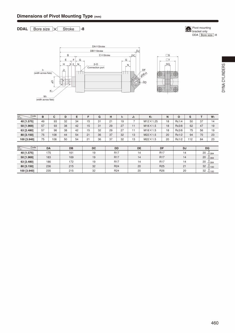
460
φD
J1
K1
(width across flats)W1
(width across flats)I1
G G
C+Stroke
F
B
DA+Stroke
DB+Stroke
23 N NH
E
DQ
T
S
φDEH9
DD
DF
DC
DJ
2-OConnection port
40 [1.575]
50 [1.969]
63 [2.480]
80 [3.150]
100 [3.940]
B
49
57
57
75
75
C
93
93
96
108
108
D
32
38
38
44
50
E
34
42
42
54
54
F
15
15
15
21
21
G
31
31
32
36
36
H
21
29
29
37
37
I1
19
27
27
32
32
J1
7
11
11
13
13
N
18
18
18
20
20
O
Rc1/4
Rc3/8
Rc3/8
Rc1/2
Rc1/2
W1
14
19
19
23
23
T
37
47
56
70
84
S
50
62
75
94
112
K1
M12×1.25
M18×1.5
M18×1.5
M22×1.5
M22×1.5
Code
40 [1.575]
50 [1.969]
63 [2.480]
80 [3.150]
100 [3.940]
DA
175
183
186
236
235
DB
161
169
172
215
215
DC
19
19
19
32
32
DD
R17
R17
R17
R24
R24
DE
14
14
14
20
20
DF
R17
R17
R17
R25
R26
DJ
14
14
14
21
20
DQ
20
20
20
32
32
Code
DDAL -8Bore size × Stroke
Dimensions of Pivot Mounting Type (mm)
–0–0.084–0–0.084–0–0.084–0–0.100–0–0.100
Pivot mounting bracket only DDA -8Bore size
Bore mm [in.]
Bore mm [in.]
DYNA
CYL
INDE
RS
460_461ダイナシリンダ_ENG 07.8.25 11:10 AM ページ460

461
HF
HE
HRHQ
HI
HJ
HT
4‐φHP
φEPe9
/H9
HB
HD
HA
EC
EEEG EG
EB
φE
Pe9
ED
ER
G G
C+Stroke
F
B
A+Stroke
φD
T
S
23 N
R
φD
NHI1
J1
E
K1
(width across flats)W1
2-OConnection port
ET
Stroke2EA+
40 [1.575]
50 [1.969]
63 [2.480]
80 [3.150]
100 [3.940]
A
144
152
155
185
185
B
49
57
57
75
75
C
93
93
96
108
108
D
32
38
38
44
50
E
34
42
42
54
54
F
15
15
15
21
21
G
31
31
32
36
36
H
21
29
29
37
37
I1
19
27
27
32
32
J1
7
11
11
13
13
W1
14
19
19
23
23
T
37
47
56
70
84
S
50
62
75
94
112
R
2
2
2
2
2
N
18
18
18
20
20
O
Rc1/4
Rc3/8
Rc3/8
Rc1/2
Rc1/2
K1
M12×1.25
M18×1.5
M18×1.5
M22×1.5
M22×1.5
Code
Dimensions of Trunnion Type (mm)
40 [1.575]
50 [1.969]
63 [2.480]
80 [3.150]
100 [3.940]
EA
95.5
103.5
105
129
129
EB
113
126
138
164
182
EC
60
72
87
105
129
ED
30
30
40
40
44
EE
63
76
88
114
132
EG
25
25
25
25
25
EP
25
25
25
25
25
ER
R1.6
R1.6
R1.6
R1.6
R2
ET
30
30
30
35
40
Code
DDAL -11Bore size × Stroke
40 [1.575]
50 [1.969]
63 [2.480]
80 [3.150]
100 [3.940]
HA
111
111
111
121
121
HB
80
80
80
85
85
HD
R22
R22
R22
R22
R22
HE
109
122
134
160
178
HF
86
99
111
137
155
HI
80
86
93.5
122.5
134.5
HJ
50
50
50
70
70
HP
12(Thru hole)
12(Thru hole)
12(Thru hole)
14(Thru hole)
14(Thru hole)
HQ
23
23
23
23
23
HR
2
2
2
2
2
HT
14
14
14
14
14
EP
25
25
25
25
25
Code
DDALWith Supporting Brackets -11-11TBore size × Stroke
Trunnion bracket onlyDDA -11Bore size
Trunnion supportingbracket onlyDDA -11TBore size
Bore mm [in.]
Bore mm [in.]
Bore mm [in.]
460_461ダイナシリンダ_ENG 07.8.25 11:10 AM ページ461

462
Symbol
Specifications
Operation type
Media
Mounting type
Operating pressure range MPa [psi.]
Proof pressure MPa [psi.]
Operating temperature range °C [°F]
Operating speed range mm/s [in./sec.]
Cushion
Cushion stroke mm [in.]
Lubrication
Port size Rc
Double acting type
Air
Basic type, Foot type, Axial foot type, Flange type, Trunnion type
0.1~1.0 [15~145]
1.5 [218]
―10~70 [14~158] (Freezing prohibited, With sensor is 0~60 [32~140].)
16 [0.630]
Not required (If lubrication is required, use Turbine Oil Class 1 (ISO VG32) or equivalent.)
1/8
25 [0.984]
32 [1.260]Bore size mm [in.]Item 40 [1.575] 50 [1.969] 63 [2.480] 80 [3.150] 100 [3.940] 125 [4.921]
50~800 [2.0~31.5] 50~700 [2.0~27.6]
Variable cushion at both ends of stroke
20 [0.787]
1/4 3/8 1/2
mm
Bore
sizeStandard strokes
Maximumavailable
stroke50, 75, 100, 150, 200, 250, 300, 350, 400, 450, 500 500
800
1000
50, 75, 100, 150, 200, 250, 300, 350, 400, 450, 500
600, 700, 800
50, 75, 100, 150, 200, 250, 300, 350, 400, 450, 500
600, 700, 800, 900, 1000
32
40
50
63
80
100
125
Bore Size and Stroke
Order Codes
Mounting typeBlank Basic type1 Foot mounting type2 Axial foot mounting type3 Flange mounting type
11 Trunnion type11-11T Trunnion type (with supporting brackets)Mounting brackets are already assembled at shipping.Orders for mounting brackets only are also accepted.
Bore size×
Stroke
DDA 50×100 - - - -
Cylinder specificationD Double rod cylinderDJ Double rod cylinder
with bellows
Types of bellowsJT Nylon tarpaulin (~80°C [176°F])JC Chloroprene (~100°C [212°F])JK Conex (~200°C [392°F])JA Alumix (~250°C [482°F])Mounted on both sides.Conex is a registered trademark of Teijin, Inc.The temperatures shown are the bellows’
own durable temperatures, and are nottemperatures for cylinder use.
DYNA CylinderBasic model
DYNA DOUBLE RODCYLINDERS
Remarks: 1. Stroke tolerance; Strokes of 250 or less:
Strokes of 251~1000:
2. For non-standard strokes, consult us.3. For the maximum available stroke with bellows
specification, see p.538.
+10
+0.039in.+0.039in.[ ]
+1.5+0
+0.059in.+0.059in.[ ]
Sensor switch (For cylinder with magnet)ZC130 2-lead wire Solid state type with indicator lamp DC10~28VZC153 3-lead wire Solid state type with indicator lamp DC4.5~28VCS5T 2-lead wire Reed switch type without indicator lamp DC5~28V
AC85~115VCS11T 2-lead wire Reed switch type with indicator lamp DC10~28VCS2F DIN type Reed switch type with indicator lamp AC85~230VCS3F DIN type Reed switch type with indicator lamp DC10~30VCS4F DIN type Reed switch type with indicator lamp DC10~30VCS5F DIN type Reed switch type without indicator lamp DC3~30VFor mounting location of sensor switch, see p.534.CSF comes with a DIN connector. All others are grommet type.Orders for sensor switches only are also accepted.
Rod end accessoryBlank No rod end accessoryY With Y type knuckle (with pin)I With I type knuckleRod end accessory for one side is included at shipping.
If required for both sides, order separately.For order code, see p.538.
For the cylinder joint and cylinder rod end, see p.1568.Orders for rod end accessories only are also accepted.For dimensions of rod end accessories, see p.537.
( )Lead wire length
Applicable only toZC,CST types
A : 1000mm [39in.]B : 3000mm [118in.]
Number of sensor switches1 With 1 sensor switch2 With 2 sensor switches
n With n sensor switches… …
DYNA
CYL
INDE
RS
462_467ダイナシリンダ_ENG 07.8.25 11:11 AM ページ462

463
q
w
e
r
t
y
u
i
o
!0
!1
!2
!3
!4
!5
!6
Parts Rod seal
2
Piston seal
1
Cushion seal
2
Tube gasket
2
Cushion gasket
2
DRP12
DRP16
DRP20
DRP20
DRP25
DRP30
DRP35
PWP32N
PWP40N
PWP50N
PWP63N
PWP80N
PWP100N
PWP125N
CPF15
CPF20
CPF24
CPF24
CPF30
CPF35
CPF45
1.5×32
1.5×40
1.5×50
1.5×63
1.5×80
1.5×100
1.5×125
QuantityBore size mm32
40
50
63
80
100
125
Parts
Cylinder tube
Piston rod
Tie rod
Rod cover
Rod cover D
Rod bushing
Keep ring
Piston A
Cushion ring DNote 1
Split ring
Pin
Wear ring
Magnet
Cushion needle
Snap ring
Tie rod nut R
Materials
Aluminum alloy
φ32:Stainless steel, φ40~φ125:Carbon steel for machine structural use
Carbon steel for machine structural use
Aluminum die-casting
Aluminum die-casting
Oil impregnated sintered copper alloy
Aluminum alloy
Aluminum alloy
Aluminum alloy
Carbon steel for machine structural use
Carbon steel for machine structural use
Plastic
Rubber magnet
Carbon steel for machine structural use
Spring steel
Rolled steel for general structural use
kg [lb.]
Major Parts and Materials
Inner Construction and Major Parts
Seals
Bore sizemm [in.]
Zero stroke mass
Basic typeFoot
mounting typeAxial foot
mounting typeFlange
mounting typeTrunnion type
Trunnion type(with supporting
brackets)
Additional mass foreach 1mm
[0.0394in.] stroke
Mass of 1 sensor switch [w. holder] Mass of knuckle
ZCCST Note CSF
Y typeknuckle
(with pin)
I typeknuckle
32 [1.260]
40 [1.575]
50 [1.969]
63 [2.480]
80 [3.150]
100 [3.940]
125 [4.921]
0.04[0.09]
0.05[0.11]
0.22 [0.49]
0.27 [0.60]
0.34 [0.75]
0.34 [0.75]
0.87 [1.92]
1.47 [3.24]
1.47 [3.24]
0.04[0.09]
0.06[0.13]
0.046 [0.101] 0.066 [0.146]
Mass
Remark: Items marked with a star () are available as repair kits.Order codes: For double rod cylinders…SRK-NDDAD Bore size
Note: For lead wire length A (1000mm [39in.]). Calculation example: For foot mounting type with bore size of 50mm, and strokeof 100mm, 1.52+(0.00673×100)=2.193kg [4.836lb.]
!5
@2
!4!8 !9 y !6 r u @3 @1 q
e
@4 !0 i @0 !3 !2 !1 o t !7 w
Parts
Tie rod nut H
Rod end nut
Rod seal
Piston seal
Cushion seal
Cushion gasket
Tube gasket
Piston gasket
Foot mounting bracket
Axial foot mounting bracket
Flange mounting bracket
Trunnion bracket
Trunnion supporting bracket
Knuckles
Materials
Chrome-molybdenum steel
Rolled steel for general structural use
Synthetic rubber (NBR)
Synthetic rubber (NBR)
Synthetic rubber (NBR)
Synthetic rubber (NBR)
Synthetic rubber (NBR)
Synthetic rubber (NBR)
Rolled steel for general structural use
Cast iron
Rolled steel for general structural use
Cast iron
Cast iron
Cast iron Note 2
No. No.
S5
S5
S6
S6
S6
S6
S7
0.68 [1.50]
0.84 [1.85]
1.35 [2.98]
1.86 [4.10]
3.16 [6.97]
4.22 [9.31]
9.48 [20.90]
0.79 [1.74]
0.97 [2.14]
1.52 [3.35]
2.09 [4.61]
3.54 [7.81]
4.69 [10.34]
9.95 [21.94]
0.82 [1.81]
1.04 [2.29]
1.67 [3.68]
2.38 [5.25]
4.01 [8.84]
5.50 [12.13]
10.86 [23.95]
0.88 [1.94]
1.21 [2.67]
1.74 [3.84]
2.39 [5.27]
4.76 [10.50]
6.44 [14.20]
12.35 [27.23]
0.98 [2.16]
1.32 [2.91]
1.90 [4.19]
2.56 [5.64]
4.32 [9.53]
5.75 [12.68]
12.89 [28.42]
1.20 [2.65]
1.82 [4.01]
2.40 [5.29]
3.06 [6.75]
5.04 [11.11]
6.47 [14.27]
14.44 [31.84]
0.00306 [0.00675]
0.00457 [0.01008]
0.00673 [0.01484]
0.00760 [0.01676]
0.01217 [0.02683]
0.01612 [0.03554]
0.02240 [0.04939]
Piston gasket
1
P9
P12
P16
P16
P21
G25
G30
!7
!8
!9
@0
@1
@2
@3
@4
―
―
―
―
―
―
!7
!8
!9
@0
@1
@2
@3
@4
―
―
―
―
―
―
0.16 [0.35]
0.16 [0.35]
0.21 [0.46]
0.21 [0.46]
0.62 [1.37]
1.24 [2.73]
1.24 [2.73]
q
w
e
r
t
y
u
i
o
!0
!1
!2
!3
!4
!5
!6
Notes: 1. Piston B for φ32~φ50, cushion ring D for φ63~φ125.2: Only the I knuckle for φ125 is carbon steel for machine structural
use.
462_467ダイナシリンダ_ENG 07.8.25 11:11 AM ページ463

464
A1+(Stroke×2)
C+Stroke
G GT
S
N N
P P
MQ
K K
2‐OConnection port
2-Cushion needle
4×2‐L
B
FE
2
φV
H
J
φD
W(w
idth
acr
oss
flats
)
I
MQ
B+Stroke
F E+Stroke
2
φV
H
J
φD
3Note
3Note
Note: 4mm for φ125.
32 [1.260]
40 [1.575]
50 [1.969]
63 [2.480]
80 [3.150]
100 [3.940]
125 [4.921]
A1
187
191
207
210
258
258
292
N
16
18
18
18
20
20
20
O
Rc1/8
Rc1/4
Rc3/8
Rc3/8
Rc1/2
Rc1/2
Rc1/2
P
25.5
25.5
24
25
29
29
29
Q
7
10
12
12
16
18
20
S
44
50
62
75
94
112
136
T
33
37
47
56
70
84
104
V
12
16
20
20
25
30
35
W
10
14
17
17
21
26
32
B
47
49
57
57
75
75
89
C
93
93
93
96
108
108
114
D
26
32
38
38
44
50
60
E
32
34
42
42
54
54
68
F
15
15
15
15
21
21
21
G
31
31
31
32
36
36
36
H
19
21
29
29
37
37
50
I
17
22
27
27
32
36
36
J
6
8
11
11
13
14
16
K
M10×1.25
M14×1.5
M18×1.5
M18×1.5
M22×1.5
M26×1.5
M27×2
L
M 6×1 Depth 14
M 6×1 Depth 14
M 6×1 Depth 14
M 8×1.25 Depth 14
M10×1.5 Depth 15
M10×1.5 Depth 15
M12×1.75 Depth 15
Code
Code
Dimensions of Basic Type (mm)
DDAD ×Bore size Stroke
32 [1.260]
40 [1.575]
50 [1.969]
63 [2.480]
80 [3.150]
100 [3.940]
125 [4.921]
M
3
4
7
8
11
12
14
DDAD Bore size
Bore mm [in.]
Bore mm [in.]
DYNA
CYL
INDE
RS
462_467ダイナシリンダ_ENG 07.8.25 11:11 AM ページ464

465
A1+(Stroke×2)
C+Stroke
G G
B
FE
2
φV
H
J
B+Stroke
F E+Stroke
2
φV
H
J
FB+Stroke
3Note
3Note
K
(width across flats)
W
K
FB FC+Stroke
FA+Stroke
FD FG FDFG
T
S
I
4-φFPFQ
FF
FE
FS
FT
FR F
H
N N2-OConnection port
(width across flats)W
Note: 4mm for φ125.
A1
187
191
207
210
258
258
292
B
47
49
57
57
75
75
89
C
93
93
93
96
108
108
114
E
32
34
42
42
54
54
68
F
15
15
15
15
21
21
21
G
31
31
31
32
36
36
36
H
19
21
29
29
37
37
50
I
17
22
27
27
32
36
36
J
6
8
11
11
13
14
16
K
M10×1.25
M14×1.5
M18×1.5
M18×1.5
M22×1.5
M26×1.5
M27×2
N
16
18
18
18
20
20
20
O
Rc1/8
Rc1/4
Rc3/8
Rc3/8
Rc1/2
Rc1/2
Rc1/2
S
44
50
62
75
94
112
136
T
33
37
47
56
70
84
104
V
12
16
20
20
25
30
35
W
10
14
17
17
21
26
32
Code
Dimensions of Foot Mounting Type (mm)
AA
153
165
173
184
200
200
220
AB
26.5
25.5
29
26
45
45
54
AC
134
140
149
158
168
168
184
AD
9.5
12.5
12
13
16
16
18
AE
50
57
68
80
97
112
136
AF
33
36
47
56
70
84
104
AG
20.5
23.5
28
31
30
30
35
AH
28
30
36.5
41
49
57
70
AP1
9
11
11
11
14
14
18
AP2
11
13
13
13
16
16
20
AS
50
55
67.5
78.5
96
113
138
AT
3.2
3.2
3.2
3.2
4
4
6
Code
DDAD -1×Bore size Stroke
DDAD -2×Bore size Stroke
Dimensions of Axial Foot Mounting Type (mm)
32 [1.260]
40 [1.575]
50 [1.969]
63 [2.480]
80 [3.150]
100 [3.940]
125 [4.921]
32 [1.260]
40 [1.575]
50 [1.969]
63 [2.480]
80 [3.150]
100 [3.940]
125 [4.921]
A1
187
191
207
210
258
258
292
B
47
49
57
57
75
75
89
C
93
93
93
96
108
108
114
E
32
34
42
42
54
54
68
F
15
15
15
15
21
21
21
G
31
31
31
32
36
36
36
H
19
21
29
29
37
37
50
I
17
22
27
27
32
36
36
J
6
8
11
11
13
14
16
K
M10×1.25
M14×1.5
M18×1.5
M18×1.5
M22×1.5
M26×1.5
M27×2
N
16
18
18
18
20
20
20
O
Rc1/8
Rc1/4
Rc3/8
Rc3/8
Rc1/2
Rc1/2
Rc1/2
S
44
50
62
75
94
112
136
T
33
37
47
56
70
84
104
V
12
16
20
20
25
30
35
W
10
14
17
17
21
26
32
Code
FA
119
119
123
130
150
158
172
FB
57
59
67
67
88
88
106
FC
73
73
73
76
82
82
80
FD
23
23
25
27
34
38
46
FE
81
92
105
117
147
168
213
FF
63
70
83
95
121
140
175
FG
14
14
14
14
18
18
21
FH
22
25
31
38
47
57
69
FP
9
12
12
12
14
14
18
FQ
54
58
68
84
104
120
144
FR
14
16
17
22
28
30
35
FS
44
50
62
75.5
94
113
137
FT
8
8
9
9
13
14
18
Code
32 [1.260]
40 [1.575]
50 [1.969]
63 [2.480]
80 [3.150]
100 [3.940]
125 [4.921]
32 [1.260]
40 [1.575]
50 [1.969]
63 [2.480]
80 [3.150]
100 [3.940]
125 [4.921]
A1+(Stroke×2)
C+Stroke
G G
B
FE
2
φV
H
J
B+Stroke
F E+Stroke
2
φV
H
J
3 3NoteNote
K
(width across flats)
W
AB
AD AG ADAG
AC+Stroke AB+Stroke
AA+Stroke
AS
AH
AT
AF
AE
T
S
I N N2-OConnection port
Z
Viewed from ZAP1
AP
2
KW(width across flats)
Note: 4mm for φ125.
Foot mounting bracket onlyDDA -1Bore size
Axial foot mounting bracket onlyDDA -2Bore size
Bore mm [in.]
Bore mm [in.]
Bore mm [in.]
Bore mm [in.]
462_467ダイナシリンダ_ENG 07.8.25 11:11 AM ページ465

466
A1+(Stroke×2)
C+Stroke
G G
B
BBBA
φV
H
5
J
B+Stroke
F E+Stroke
2
φV
H
J
φD
3Note
3Note
Note: 4mm for φ125.
K
(width across flats)
W
K
(widthacross flats)
W
N N2-OConnection port
4-φBP
BC
BD
BE
BF
T
I
A1
187
191
207
210
258
258
292
Code
Dimensions of Flange Mounting Type (mm)
B
47
49
57
57
75
75
89
C
93
93
93
96
108
108
114
D
26
32
38
38
44
50
60
E
32
34
42
42
54
54
68
F
15
15
15
15
21
21
21
G
31
31
31
32
36
36
36
H
19
21
29
29
37
37
50
I
17
22
27
27
32
36
36
J
16
18
11
11
13
14
16
K
M10×1.25
M14×1.5
M18×1.5
M18×1.5
M22×1.5
M26×1.5
M27×2
N
16
18
18
18
20
20
20
O
Rc1/8
Rc1/4
Rc3/8
Rc3/8
Rc1/2
Rc1/2
Rc1/2
T
33
37
47
56
70
84
104
V
12
16
20
20
25
30
35
W
10
14
17
17
21
26
32
32 [1.260]
40 [1.575]
50 [1.969]
63 [2.480]
80 [3.150]
100 [3.940]
125 [4.921]
BA
37
39
47
47
59
59
73
BB
10
10
10
10
16
16
16
BC
47
52
65
76
95
115
138
BD
33
36
47
56
70
84
104
BE
72
84
104
116
143
162
196
BF
58
70
86
98
119
138
168
Code
DDAD -3×Bore size Stroke
32 [1.260]
40 [1.575]
50 [1.969]
63 [2.480]
80 [3.150]
100 [3.940]
125 [4.921]
BP
7
7
9
9
12
12
14
Flange mounting bracket onlyDDA -3Bore size
Bore mm [in.]
Bore mm [in.]
DYNA
CYL
INDE
RS
462_467ダイナシリンダ_ENG 07.8.25 11:11 AM ページ466

467
HB
HD
HA
HF
HE
HRHQ
HJ
HT
4‐φHP
φEPe9/H9
HI
A1+(Stroke×2)
C+Stroke
G G
B
FE
2
φV
H
J
φD
B+Stroke
F E+Stroke
2
φV
H
J
φD
3Note
3Note
ET
Stroke2EA+
T
S
I
EEEG EG
EB
φE
Pe9
EC
ED
N N2-OConnection port
K
(width across flats)W
K
(width across flats)
W
ER
Note: 4mm for φ125.
32 [1.260]
40 [1.575]
50 [1.969]
63 [2.480]
80 [3.150]
100 [3.940]
125 [4.921]
A1
187
191
207
210
258
258
292
Code
Dimensions of Trunnion Type (mm)
B
47
49
57
57
75
75
89
C
193
193
193
196
108
108
114
D
26
32
38
38
44
50
60
E
32
34
42
42
54
54
68
F
15
15
15
15
21
21
21
G
31
31
31
32
36
36
36
H
19
21
29
29
37
37
50
I
17
22
27
27
32
36
36
J
16
18
11
11
13
14
16
K
M10×1.25
M14×1.5
M18×1.5
M18×1.5
M22×1.5
M26×1.5
M27×2
N
16
18
18
18
20
20
20
O
Rc1/8
Rc1/4
Rc3/8
Rc3/8
Rc1/2
Rc1/2
Rc1/2
S
144
150
162
175
194
112
136
T
133
137
147
156
170
184
104
V
12
16
20
20
25
30
35
W
10
14
17
17
21
26
32
EA
93.5
95.5
103.5
105
129
129
146
EB
87
113
126
138
164
182
208
EC
53
60
72
87
105
129
159
ED
20
30
30
40
40
44
37.5
EE
55
63
76
88
114
132
158
EG
16
25
25
25
25
25
25
EP
16
25
25
25
25
25
25
ER
R1
R1.6
R1.6
R1.6
R1.6
R2
R2
ET
30
30
30
30
35
40
43
Code
DDAD -11×Bore size Stroke
HA
81
111
111
111
121
121
145
HB
160
180
180
180
185
185
105
HD
R16
R22
R22
R22
R22
R22
R30
HE
185
109
122
134
160
178
208
HF
170
186
199
111
137
155
183
HI
66.5
80
86
93.5
122.5
134.5
164.5
HJ
40
50
50
50
70
70
85
HP
9 (Thru hole)
12 (Thru hole)
12 (Thru hole)
12 (Thru hole)
14 (Thru hole)
14 (Thru hole)
18 (Thru hole)
HQ
15
23
23
23
23
23
25
HR
1
2
2
2
2
2
0
HT
12
14
14
14
14
14
27
EP
16
25
25
25
25
25
25
Code
DDADWith Supporting Brackets -11-11T×Bore size Stroke
32 [1.260]
40 [1.575]
50 [1.969]
63 [2.480]
80 [3.150]
100 [3.940]
125 [4.921]
32 [1.260]
40 [1.575]
50 [1.969]
63 [2.480]
80 [3.150]
100 [3.940]
125 [4.921]
Trunnion bracket onlyDDA -11Bore size
Trunnion supportingbracket onlyDDA -11TBore size
Bore mm [in.]
Bore mm [in.]
Bore mm [in.]
462_467ダイナシリンダ_ENG 07.8.25 11:11 AM ページ467

468
Symbol
Specifications
Order Codes
Bore Size and Stroke
Operation type
Media
Mounting type
Operating pressure range MPa [psi.]
Proof pressure MPa [psi.]
Operating temperature range °C [°F]
Operating speed range mm/s [in./sec.]
Cushion
Cushion stroke mm [in.]
Lubrication
Non-rotating accuracy
Allowable torque N·m [ft·lbf]
Port size Rc
Double acting type
Air
Basic type, Foot type, Axial foot type, Flange type, Trunnion type
0.15~1.0 [22~145]
1.5 [218]
―10~70 [14~158] (Freezing prohibited, With sensor is 0~60 [32~140].)
50~500 [2.0~19.7]
Variable cushion at both ends of stroke
Not required (If lubrication is required, use Turbine Oil Class 1 (ISO VG32) or equivalent.)
1/4 3/8 1/2
1 [0.74] 3.4 [2.51] 10 [7.38]
±1° ±0.8° ±0.5°
16 [0.630] 20 [0.787] 25 [0.984]
40 [1.575] 50 [1.969] 63 [2.480] 80 [3.150] 100 [3.940]Bore size mm [in.]Item
mm
Bore
sizeStandard strokes
Maximumavailable
stroke
50050, 75, 100, 150, 200, 250, 300, 350, 400, 450, 500
40
50
63
80
100
Mounting typeBlank Basic type1 Foot mounting type2 Axial foot mounting type3 Flange mounting type
11 Trunnion type11-11T Trunnion type (with supporting brackets)Mounting brackets are already assembled at
shipping.Orders for mounting brackets only are also accepted.
Bore size×
Stroke
DDA 50×100 - - - - -
Rod end accessoryBlank No rod end accessoryY With Y type knuckle (with pin)I With I type knuckleRod end accessory for one side is included at shipping.
If required for both sides, order separately.For order code, see p.538.
For the cylinder joint and cylinder rod end, see p.1568.Orders for rod end accessories only are also accepted.For dimensions of rod end accessories, see p.537.
Cylinder specificationDL Non-rotating double rod cylinderDJL Non-rotating double rod cylinder with bellows
Types of bellowsJT Nylon tarpaulin (~80°C [176°F])JC Chloroprene (~100°C [212°F])JK Conex (~200°C [392°F])JA Alumix (~250°C [482°F])Conex is a registered trademark of Teijin,
Inc.The temperatures shown are the bellows’
own durable temperatures, and are nottemperatures for cylinder use.
DYNA CylinderBasic model
DYNA NON-ROTATING DOUBLE ROD CYLINDERS
Remarks: 1. Stroke tolerance; Strokes of 250 or less:
Strokes of 251~500:
2. For non-standard strokes, consult us.3. For the maximum available stroke with bellows
specification, see p.538.
+10
+0.039in.+0.039in.[ ]
+1.5+0
+0.059in.+0.059in.[ ]
( )
Tube materialBlank StandardFT Steel tube specification
Not available for cylinder with magnet.
Sensor switch (For cylinder with magnet)ZC130 2-lead wire Solid state type with indicator lamp DC10~28VZC153 3-lead wire Solid state type with indicator lamp DC4.5~28VCS5T 2-lead wire Reed switch type without indicator lamp DC5~28V
AC85~115VCS11T 2-lead wire Reed switch type with indicator lamp DC10~28VCS2F DIN type Reed switch type with indicator lamp AC85~230VCS3F DIN type Reed switch type with indicator lamp DC10~30VCS4F DIN type Reed switch type with indicator lamp DC10~30VCS5F DIN type Reed switch type without indicator lamp DC3~30VFor mounting location of sensor switch, see p.534.CSF comes with a DIN connector. All others are grommet type.Orders for sensor switches only are also accepted.
( )Lead wire length
Applicable only toZC,CST types
A : 1000mm [39in.]B : 3000mm [118in.]
Number of sensor switches1 With 1 sensor switch2 With 2 sensor switches
n With n sensor switches… …
DYNA
CYL
INDE
RS
468_473ダイナシリンダ_END 07.8.25 11:12 AM ページ468

469
Parts Rod seal A
1
Piston seal
1
Tube gasket
2
Cushion gasket
2
PGR14A
PGR19
PGR19
PGR23
PGR23
Rod seal B
1
DRP16
DRP20
DRP20
DRP25
DRP30
PWP40N
PWP50N
PWP63N
PWP80N
PWP100N
1.5×40
1.5×50
1.5×63
1.5×80
1.5×100
Cushion seal
2
CPF20
CPF24
CPF24
CPF30
CPF35
S5
S6
S6
S6
S6
Piston gasket
1
S10
S14
S14
S18
S18
QuantityBore size mm40
50
63
80
100
Parts
Cylinder tube
Piston rod A
Piston rod B
Tie rod
Rod cover A
Rod cover B
Rod bushing A
Rod bushing B
Keep ring
Piston
Wear ring
Magnet
q
w
e
r
t
y
u
i
o
!0
!1
!2
No.
q
w
e
r
t
y
u
i
o
!0
!1
!2
Materials
Aluminum alloy, and steel tube specification is steel
Carbon steel for machine structural use
Carbon steel for machine structural use
Carbon steel for machine structural use
Aluminum die-casting
Aluminum die-casting
Aluminum alloy
Oil impregnated sintered copper alloy
Aluminum alloy
Aluminum alloy
Plastic
Rubber magnet
kg [lb.]
Major Parts and Materials
Inner Construction and Major Parts
Seals
Bore sizemm [in.]
Zero stroke mass
Basic type0.84 [1.85]
(0.88 [1.94])1.35 [2.98]
(1.41 [3.11])1.86 [4.10]
(1.94 [4.28])3.16 [6.97]
(3.33 [7.34])4.22 [9.31]
(4.43 [9.77])
0.97 [2.14](1.01 [2.23])1.52 [3.35]
(1.58 [3.48])2.09 [4.61]
(2.17 [4.78])3.54 [7.81]
(3.71 [8.18])4.69 [10.34]
(4.90 [10.80])
1.04 [2.29](1.08 [2.38])1.67 [3.68]
(1.73 [3.81])2.38 [5.25]
(2.46 [5.42])4.01 [8.84]
(4.18 [9.22])5.50 [12.13]
(5.71 [12.59])
1.21 [2.67](1.25 [2.76])1.74 [3.84]
(1.80 [3.97])2.39 [5.27]
(2.47 [5.45])4.76 [10.50]
(4.93 [10.87])6.44 [14.20]
(6.65 [14.66])
1.32 [2.91](1.36 [3.00])1.90 [4.19]
(1.96 [4.32])2.56 [5.64]
(2.64 [5.82])4.32 [9.53]
(4.49 [9.90])5.75 [12.68]
(5.96 [13.14])
1.82 [4.01](1.86 [4.10])2.40 [5.29]
(2.46 [5.42])3.06 [6.75]
(3.14 [6.92])5.04 [11.11]
(5.21 [11.49])6.47 [14.27]
(6.68 [14.73])
0.00433 [0.00955](0.00564 [0.01244])0.00670 [0.01477]
(0.00877 [0.01934])0.00757 [0.01669]
(0.01015 [0.02238])0.01193 [0.02631]
(0.01661 [0.03663])0.01420 [0.03131]
(0.02001 [0.04412])
0.04[0.09]
0.04[0.09]
0.05[0.11]
0.27 [0.60]
0.34 [0.75]
0.34 [0.75]
0.87 [1.92]
0.16 [0.35]
0.21 [0.46]
0.21 [0.46]
0.62 [1.37]0.06[0.13]
Foot mounting type Axial foot mounting type Flange mounting type Trunnion type Trunnion type
(w. supporting bkt.)
Additional mass for each1mm [0.0394in.] stroke
Mass of 1 sensor switch [w. holder] Mass of knuckleZCCST Note CSF Y type knuckle
(with pin)
A side 0.87 [1.92]B side 1.47 [3.24]
A side 0.62 [1.37]B side 1.24 [2.73]
I type knuckle
40 [1.575]
50 [1.969]
63 [2.480]
80 [3.150]
100 [3.940]
Mass
!4@3!3
!1!2 @4!0q@5r @1@4o @2 e@0!6y i@2 o!5!8 t!9w u!7
Note: For lead wire length A (1000mm [39in.]).Remarks: 1. Figures in parentheses ( ) are for steel tube specification.Remarks: 2. A side=Non-rotating side
Parts
Cushion needle
Snap ring
Tie rod nut R
Tie rod nut H
Rod end nut
Spring pin
Rod seal A
Rod seal B
Piston seal
Cushion seal
Cushion gasket
Tube gasket
Piston gasket
!3
!4
!5
!6
!7
!8
!9
@0
@1
@2
@3
@4
@5
No.
!3
!4
!5
!6
!7
!8
!9
@0
@1
@2
@3
@4
@5
Materials
Carbon steel for machine structural use
Spring steel
Rolled steel for general structural use
Chrome-molybdenum steel
Rolled steel for general structural use
Carbon steel for machine structural use
Urethane rubber
Synthetic rubber (NBR)
Synthetic rubber (NBR)
Synthetic rubber (NBR)
Synthetic rubber (NBR)
Synthetic rubber (NBR)
Synthetic rubber (NBR)
A side B side
Calculation example: For foot mounting type with bore size of 50mm, and stroke of100mm, 1.52+(0.00670×100)=2.19kg [4.83lb.]
Remark: Items marked with a star () are available as repair kits.Order codes: For non-rotating double rod cylinders…SRK-NDDADL Bore size
468_473ダイナシリンダ_END 07.8.25 11:12 AM ページ469

470
GF
B
φD
T
S
N
P
MQ
2‐OConnection port
N
P
MQ
2
K1
4×2‐L W1
HI1
J1
E
(width across flats)
2-Cushion needle
G F
φD
φV
2
K
W
H
J
(width across flats)
I(width across flats)
A1+(Stroke×2)
C+Stroke B+Stroke
E+Stroke
3 3
40 [1.575]
50 [1.969]
63 [2.480]
80 [3.150]
100 [3.940]
40 [1.575]
50 [1.969]
63 [2.480]
80 [3.150]
100 [3.940]
A1
191
207
210
258
258
N
18
18
18
20
20
O
Rc1/4
Rc3/8
Rc3/8
Rc1/2
Rc1/2
P
25.5
24
25
29
29
Q
10
12
12
16
18
S
50
62
75
94
112
T
37
47
56
70
84
V
16
20
20
25
30
W
14
17
17
21
26
W1
14
19
19
23
23
B
49
57
57
75
75
C
93
93
96
108
108
D
32
38
38
44
50
E
34
42
42
54
54
F
15
15
15
21
21
G
31
31
32
36
36
H
21
29
29
37
37
I
22
27
27
32
36
I1
19
27
27
32
32
J
8
11
11
13
14
J1
7
11
11
13
13
K
M14×1.5
M18×1.5
M18×1.5
M22×1.5
M26×1.5
K1
M12×1.25
M18×1.5
M18×1.5
M22×1.5
M22×1.5
L
M 6×1 Depth 14
M 6×1 Depth 14
M 8×1.25 Depth 14
M10×1.5 Depth 15
M10×1.5 Depth 15
Code
Code
Dimensions of Basic Type (mm)
DDADL ×Bore size Stroke
M
4
7
8
11
12
DDADL Bore size
Bore mm [in.]
Bore mm [in.]
DYNA
CYL
INDE
RS
468_473ダイナシリンダ_END 07.8.25 11:12 AM ページ470

471
GF
B
23H
J1
E
K
W(width across flats)
G F
2 H3
J
φV
A1+(Stroke×2)
C+Stroke B+Stroke
E+Stroke
AD AG ADAG
AS
AH
AT
AF
AE
T
S
I1
AC+Stroke AB+Stroke
AA+Stroke
N N2-OConnection port
I(width across flats)
K1
(width across flats)
W1
AB
Z
Viewed from Z
AP1
AP
2
40 [1.575]
50 [1.969]
63 [2.480]
80 [3.150]
100 [3.940]
Code
Dimensions of Foot Mounting Type (mm)
40 [1.575]
50 [1.969]
63 [2.480]
80 [3.150]
100 [3.940]
AA
165
173
184
200
200
AB
25.5
29
26
45
45
AC
140
149
158
168
168
AD
12.5
12
13
16
16
AE
57
68
80
97
112
AF
36
47
56
70
84
AG
23.5
28
31
30
30
AH
30
36.5
41
49
57
AP1
11
11
11
14
14
AP2
13
13
13
16
16
AS
55
67.5
78.5
96
113
AT
3.2
3.2
3.2
4
4
Code
DDADL -1Bore size × Stroke
DDADL -2Bore size × Stroke
GF
B
23H
J1
E G F
2 H3
J
A1+(Stroke×2)
C+Stroke B+Stroke
E+Stroke
K
W(width across flats)
K1
(width across flats)W1
T
S
I1
4-φFP
FB FC+Stroke FB+Stroke
FA+Stroke
FQ
FF
FE
FD FG FDFG
FS
FT
FR F
H
N N2-OConnection portφ
V
I(width across flats)
Dimensions of Axial Foot Mounting Type (mm)
40 [1.575]
50 [1.969]
63 [2.480]
80 [3.150]
100 [3.940]
FA
119
123
130
150
158
FB
59
67
67
88
88
FC
73
73
76
82
82
FD
23
25
27
34
38
FE
92
105
117
147
168
FF
70
83
95
121
140
FG
14
14
14
18
18
FH
25
31
38
47
57
FP
12
12
12
14
14
FQ
58
68
84
104
120
FR
16
17
22
28
30
FS
50
62
75.5
94
113
FT
8
9
9
13
14
Code
A1
191
207
210
258
258
B
49
57
57
75
75
C
93
93
96
108
108
E
34
42
42
54
54
F
15
15
15
21
21
G
31
31
32
36
36
H
21
29
29
37
37
I
22
27
27
32
36
I1
19
27
27
32
32
J
8
11
11
13
14
J1
7
11
11
13
13
K
M14×1.5
M18×1.5
M18×1.5
M22×1.5
M26×1.5
K1
M12×1.25
M18×1.5
M18×1.5
M22×1.5
M22×1.5
N
18
18
18
20
20
O
Rc1/4
Rc3/8
Rc3/8
Rc1/2
Rc1/2
S
50
62
75
94
112
T
37
47
56
70
84
V
16
20
20
25
30
W
14
17
17
21
26
W1
14
19
19
23
23
40 [1.575]
50 [1.969]
63 [2.480]
80 [3.150]
100 [3.940]
Code A1
191
207
210
258
258
B
49
57
57
75
75
C
93
93
96
108
108
E
34
42
42
54
54
F
15
15
15
21
21
G
31
31
32
36
36
H
21
29
29
37
37
I
22
27
27
32
36
I1
19
27
27
32
32
J
8
11
11
13
14
J1
7
11
11
13
13
K
M14×1.5
M18×1.5
M18×1.5
M22×1.5
M26×1.5
K1
M12×1.25
M18×1.5
M18×1.5
M22×1.5
M22×1.5
N
18
18
18
20
20
O
Rc1/4
Rc3/8
Rc3/8
Rc1/2
Rc1/2
S
50
62
75
94
112
T
37
47
56
70
84
V
16
20
20
25
30
W
14
17
17
21
26
W1
14
19
19
23
23
Foot mounting bracket onlyDDA -1Bore size
Axial foot mounting bracket onlyDDA -2Bore size
Bore mm [in.]
Bore mm [in.]
Bore mm [in.]
Bore mm [in.]
468_473ダイナシリンダ_END 07.8.25 11:12 AM ページ471

472
GBB
B
5
H 3
J1
BA
K
W(width across flats)
G F
φD
φV
2 H3
J
A1+(Stroke×2)
C+Stroke B+Stroke
E+Stroke
K1
(width across flats)W1
4-φBP
BC
BD
BE
BF
T
I1 N N2-OConnection port
I(width across flats)
40 [1.575]
50 [1.969]
63 [2.480]
80 [3.150]
100 [3.940]
A1
191
207
210
258
258
B
49
57
57
75
75
C
93
93
96
108
108
D
32
38
38
44
50
E
34
42
42
54
54
F
15
15
15
21
21
G
31
31
32
36
36
H
21
29
29
37
37
I
22
27
27
32
36
I1
19
27
27
32
32
J
8
11
11
13
14
J1
7
11
11
13
13
K
M14×1.5
M18×1.5
M18×1.5
M22×1.5
M26×1.5
K1
M12×1.25
M18×1.5
M18×1.5
M22×1.5
M22×1.5
N
18
18
18
20
20
O
Rc1/4
Rc3/8
Rc3/8
Rc1/2
Rc1/2
T
37
47
56
70
84
V
16
20
20
25
30
W
14
17
17
21
26
W1
14
19
19
23
23
Code
Dimensions of Flange Mounting Type (mm)
40 [1.575]
50 [1.969]
63 [2.480]
80 [3.150]
100 [3.940]
BA
39
47
47
59
59
BB
10
10
10
16
16
BC
52
65
76
95
115
BD
36
47
56
70
84
BE
84
104
116
143
162
BF
70
86
98
119
138
BP
7
9
9
12
12
Code
DDADL -3Bore size × Stroke Flange mounting bracket onlyDDA -3Bore size
Bore mm [in.]
Bore mm [in.]
DYNA
CYL
INDE
RS
468_473ダイナシリンダ_END 07.8.25 11:12 AM ページ472

473
40 [1.575]
50 [1.969]
63 [2.480]
80 [3.150]
100 [3.940]
Code
GF
B
φD
23H
J1
E
K
W(width across flats)
G F
φD
φV
2 H3
J
A1+(Stroke×2)
C+Stroke B+Stroke
E+Stroke
K1
(width across flats)W1
T
S
I1
ET
Stroke2EA+
EEEG EG
EB
EC
ED
ERN N2-O
Connection port I(width across flats)
φE
Pe9
40 [1.575]
50 [1.969]
63 [2.480]
80 [3.150]
100 [3.940]
Code
40 [1.575]
50 [1.969]
63 [2.480]
80 [3.150]
100 [3.940]
Code
DDADL -11Bore size × Stroke
DDADLWith Supporting Brackets -11-11TBore size × Stroke
Dimensions of Trunnion Type (mm)
HB
HD
HA
HF
HE
HRHQ
HJ
HT
4‐φHP
φEPe9/H9
HI
A1
191
207
210
258
258
B
49
57
57
75
75
C
93
93
96
108
108
D
32
38
38
44
50
E
34
42
42
54
54
F
15
15
15
21
21
G
31
31
32
36
36
H
21
29
29
37
37
I
22
27
27
32
36
I1
19
27
27
32
32
J
8
11
11
13
14
J1
7
11
11
13
13
K
M14×1.5
M18×1.5
M18×1.5
M22×1.5
M26×1.5
K1
M12×1.25
M18×1.5
M18×1.5
M22×1.5
M22×1.5
N
18
18
18
20
20
O
Rc1/4
Rc3/8
Rc3/8
Rc1/2
Rc1/2
S
50
62
75
94
112
T
37
47
56
70
84
V
16
20
20
25
30
W
14
17
17
21
26
W1
14
19
19
23
23
EA
95.5
103.5
105
129
129
EB
113
126
138
164
182
EC
60
72
87
105
129
ED
30
30
40
40
44
EE
63
76
88
114
132
EG
25
25
25
25
25
EP
25
25
25
25
25
ER
R1.6
R1.6
R1.6
R1.6
R2
ET
30
30
30
35
40
HA
111
111
111
121
121
HB
80
80
80
85
85
HD
R22
R22
R22
R22
R22
HE
109
122
134
160
178
HF
86
99
111
137
155
HI
80
86
93.5
122.5
134.5
HJ
50
50
50
70
70
HP
12(Thru hole)
12(Thru hole)
12(Thru hole)
14(Thru hole)
14(Thru hole)
HQ
23
23
23
23
23
HR
2
2
2
2
2
HT
14
14
14
14
14
EP
25
25
25
25
25
Trunnion bracket onlyDDA -11Bore size
Trunnion supportingbracket onlyDDA -11TBore size
Bore mm [in.]
Bore mm [in.]
Bore mm [in.]
468_473ダイナシリンダ_END 07.8.25 11:13 AM ページ473
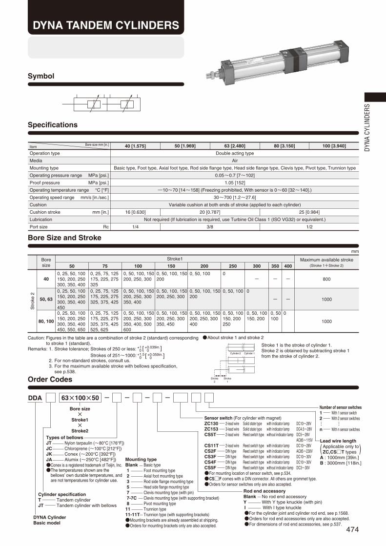
474
Symbol
Specifications
Operation type
Media
Mounting type
Operating pressure range MPa [psi.]
Proof pressure MPa [psi.]
Operating temperature range °C [°F]
Operating speed range mm/s [in./sec.]
Cushion
Cushion stroke mm [in.]
Lubrication
Port size Rc
Double acting type
Air
Basic type, Foot type, Axial foot type, Rod side flange type, Head side flange type, Clevis type, Pivot type, Trunnion type
0.05~0.7 [7~102]
1.05 [152]
―10~70 [14~158] (Freezing prohibited, With sensor is 0~60 [32~140].)
30~700 [1.2~27.6]
Variable cushion at both ends of stroke (applied to each cylinder)
16 [0.630]
Not required (If lubrication is required, use Turbine Oil Class 1 (ISO VG32) or equivalent.)
25 [0.984]
Bore size mm [in.]Item 40 [1.575] 50 [1.969] 63 [2.480] 80 [3.150] 100 [3.940]
20 [0.787]
1/4 3/8 1/2
About stroke 1 and stroke 2
Stroke 1 is the stroke of cylinder 1.Stroke 2 is obtained by subtracting stroke 1from the stroke of cylinder 2.
mm
Boresize
Str
oke
2
Stroke1 Maximum available stroke(Stroke 1+Stroke 2)50
0, 25, 50, 100150, 200, 250300, 350, 400
0, 25, 75, 125175, 225, 275325
0, 50, 100, 150200, 250, 300
0, 50, 100, 150200
0, 50, 100 0- -
-
0, 50100
0
-
- 800
1000
1000
0
0, 50, 100150, 200
0, 50, 100
0, 50, 100150, 200250
0, 50, 100, 150200
0, 50, 100, 150200, 250, 300400
0, 50, 100, 150200, 250, 300
0, 50, 100, 150200, 250, 300350, 450
0, 50, 100, 150200, 250, 300350, 400
0, 50, 100, 150200, 250, 300350, 400, 500600
0, 25, 75, 125175, 225, 275325, 375, 425
0, 25, 75, 125175, 225, 275325, 375, 425525, 625
0, 25, 50, 100150, 200, 250300, 350, 4004500, 25, 50, 100150, 200, 250300, 350, 400450, 550, 650
75 100 150 200 250 300 350 400
40
50, 63
80, 100
Order Codes
Bore Size and Stroke
Bore size×
Stroke1×
Stroke2
DDA 63×100×50 --- -
Mounting typeBlank Basic type1 Foot mounting type2 Axial foot mounting type3 Rod side flange mounting type5 Head side flange mounting type7 Clevis mounting type (with pin)7-7C Clevis mounting type (with supporting bracket)8 Pivot mounting type
11 Trunnion type11-11T Trunnion type (with supporting brackets)Mounting brackets are already assembled at shipping.Orders for mounting brackets only are also accepted.
Cylinder 2 Cylinder 1
Stroke2
Stroke1
DYNA CylinderBasic model
Types of bellowsJT Nylon tarpaulin (~80°C [176°F])JC Chloroprene (~100°C [212°F])JK Conex (~200°C [392°F])JA Alumix (~250°C [482°F])Conex is a registered trademark of Teijin, Inc.The temperatures shown are the
bellows’ own durable temperatures, andare not temperatures for cylinder use.
Cylinder specificationT Tandem cylinderJT Tandem cylinder with bellows
DYNA TANDEM CYLINDERS
Caution: Figures in the table are a combination of stroke 2 (standard) correspondingto stroke 1 (standard).
Remarks: 1. Stroke tolerance; Strokes of 250 or less: Strokes of 251~1000:
2. For non-standard strokes, consult us.3. For the maximum available stroke with bellows specification,
see p.538.
+10
+0.039in.+0.039in.[ ]
+1.5+0
+0.059in.+0.059in.[ ]
Sensor switch (For cylinder with magnet)ZC130 2-lead wire Solid state type with indicator lamp DC10~28VZC153 3-lead wire Solid state type with indicator lamp DC4.5~28VCS5T 2-lead wire Reed switch type without indicator lamp DC5~28V
AC85~115VCS11T 2-lead wire Reed switch type with indicator lamp DC10~28VCS2F DIN type Reed switch type with indicator lamp AC85~230VCS3F DIN type Reed switch type with indicator lamp DC10~30VCS4F DIN type Reed switch type with indicator lamp DC10~30VCS5F DIN type Reed switch type without indicator lamp DC3~30VFor mounting location of sensor switch, see p.534.CSF comes with a DIN connector. All others are grommet type.Orders for sensor switches only are also accepted.
Rod end accessoryBlank No rod end accessoryY With Y type knuckle (with pin)I With I type knuckleFor the cylinder joint and cylinder rod end, see p.1568.Orders for rod end accessories only are also accepted.For dimensions of rod end accessories, see p.537.
Number of sensor switches1 With 1 sensor switch2 With 2 sensor switches
n With n sensor switches… …
( )Lead wire length
Applicable only toZC,CST types
A : 1000mm [39in.]B : 3000mm [118in.]
DYNA
CYL
INDE
RS
474_481ダイナシリンダ_ENG 07.8.25 11:13 AM ページ474

475
Parts Rod seal A
2
Rod seal B
1
Piston seal
2
Cushion seal
4
Tube gasket
4
Cushion gasket
4
Piston gasket
1
DRP16
DRP20
DRP20
DRP25
DRP30
PNU16
PNU20
PNU20
PNU25
PNU30
PWP40N
PWP50N
PWP63N
PWP80N
PWP100N
CPF20
CPF24
CPF24
CPF30
CPF35
1.5×40
1.5×50
1.5×63
1.5×80
1.5×100
S5
S6
S6
S6
S6
S10
S14
S14
S18
S18
QuantityBore size mm40
50
63
80
100
kg [lb.]
Inner Construction and Major Parts
Seals
Bore sizemm [in.]
Zero stroke mass
Basic type
1.40 [3.09]
2.20 [4.85]
2.97 [6.55]
5.15 [11.36]
6.61 [14.58]
1.53 [3.37]
2.37 [5.23]
3.20 [7.06]
5.53 [12.19]
7.08 [15.61]
1.60 [3.53]
2.52 [5.56]
3.49 [7.70]
6.00 [13.23]
7.89 [17.40]
1.77 [3.90]
2.59 [5.71]
3.50 [7.72]
6.75 [14.88]
8.83 [19.47]
1.67 [3.68]
2.59 [5.71]
3.45 [7.61]
6.07 [13.38]
7.85 [17.31]
2.37 [5.23]
3.29 [7.25]
4.15 [9.15]
6.79 [14.97]
8.57 [18.90]
1.58 [3.48]
2.46 [5.42]
3.39 [7.47]
6.23 [13.74]
8.00 [17.64]
1.88 [4.15]
2.75 [6.06]
3.67 [8.09]
6.31 [13.91]
8.14 [17.95]
2.38 [5.25]
3.25 [7.17]
4.17 [9.19]
7.03 [15.50]
8.86 [19.54]
0.00300 [0.00662]0.00428
[0.00944]0.00515
[0.01136]0.00834
[0.01839]0.01061
[0.02340]
0.00300 [0.00662]0.00428
[0.00944]0.00515
[0.01136]0.00834
[0.01839]0.01061
[0.02340]
0.04 [0.09]
0.04 [0.09]
0.05[0.11]
0.27 [0.60]
0.34 [0.75]
0.34 [0.75]
0.87 [1.92]
1.47 [3.24]
0.16 [0.35]
0.21 [0.46]
0.21 [0.46]
0.62 [1.37]
1.24 [2.73]
0.06 [0.13]
Foot type Axial foot type Flange type Clevis type
(with pin)Clevis type
(w. supporting bkt.) Pivot type Trunnion type Trunnion type(w. supporting bkt.)
Additional mass for each 1mm [0.0394in.] stroke
Stroke1 Stroke2
Mass of 1 sensor switch [w. holder] Mass of knuckleZCCST Note CSF Y type knuckle
(with pin) I type knuckle
40 [1.575]
50 [1.969]
63 [2.480]
80 [3.150]
100 [3.940]
Mass
Remark: Items marked with a star () are available as repair kits.Order codes: For tandem cylinders…SRK-NDDAT Bore size
@4t !8 y!1!9 !0 !5@3q oe@0 wir @2u!7 !4!6
!3@1!2
Note: For lead wire length A (1000mm [39in.]). Calculation example: For foot mounting type with bore size of 50mm, stroke1 of 100mm and stroke 2of 50mm, 2.37+(0.00428×100)+(0.00428×50)=3.012kg [6.641lb.]
Operation principle of tandem cylindersTandem Cylinders are a set of 2 cylinders joined end to end.It can be used as a 2-stage stroke cylinder by supplying air to eitherPort A or Port B. It can also obtain twice the thrust within the stroke 1range.
The rods retract strokes 2 and 1 when air issupplied from Port C.
The rod moves stroke 1 when air is suppliedfrom Port A.
The rod moves stroke 2 when air is suppliedfrom Port B.
Twice the thrust is obtained within the stroke 1range when air is supplied from Ports A and B.
AB
B
C
A
A
A
B
B
C
C
C
Cylinder 2
Stroke 2 Stroke 1
Cylinder 1
Spacer gasket
1
S25
G30
G30
G35
G40
Parts
Cylinder tube
Piston rod
Tie rod
Rod cover
Head cover
Spacer
Rod bushing
Keep ring
Piston
Wear ring
Magnet
Cushion needle
Snap ring
Tie rod nut R
Tie rod nut H
Rod end nut
Materials
Aluminum alloy
Carbon steel for machine structural use
Carbon steel for machine structural use
Aluminum die-casting
Aluminum die-casting
Aluminum alloy
Oil impregnated sintered copper alloy
Aluminum alloy
Aluminum alloy
Plastic
Rubber magnet
Carbon steel for machine structural use
Spring steel
Rolled steel for general structural use
Chrome-molybdenum steel
Rolled steel for general structural use
Major Parts and Materials
Parts
Rod seal A
Rod seal B
Piston seal
Cushion seal
Cushion gasket
Tube gasket
Piston gasket
Spacer gasket
Foot mounting bracket
Axial foot mounting bracket
Flange mounting bracket
Clevis mounting bracket
Clevis supporting bracket
Pivot mounting bracket
Trunnion bracket
Trunnion supporting bracket
Knuckles
Materials
Synthetic rubber (NBR)
Synthetic rubber (NBR)
Synthetic rubber (NBR)
Synthetic rubber (NBR)
Synthetic rubber (NBR)
Synthetic rubber (NBR)
Synthetic rubber (NBR)
Synthetic rubber (NBR)
Rolled steel for general structural use
Cast iron
Rolled steel for general structural use
Cast iron
Cast iron
Cast iron
Cast iron
Cast iron
Cast iron
No. No.
!7
!8
!9
@0
@1
@2
@3
@4
!7
!8
!9
@0
@1
@2
@3
@4
―
―
―
―
―
―
―
―
―
q
w
e
r
t
y
u
i
o
!0
!1
!2
!3
!4
!5
!6
q
w
e
r
t
y
u
i
o
!0
!1
!2
!3
!4
!5
!6
474_481ダイナシリンダ_ENG 07.8.25 11:13 AM ページ475

476
G GF
B
φV
φD
T
S
N N
P P
MQ
23
(widthacross flats)
K4×2‐L
R
φD
G
N
P
G
N
P
4-OConnection port
G2 C+Stroke1
A2+(Stroke1×2)+Stroke2
4-Cushion needle
I
J
H
E
W
C+Stroke1+Stroke2
MQ
MQ
MQ
40 [1.575]
50 [1.969]
63 [2.480]
80 [3.150]
100 [3.940]
40 [1.575]
50 [1.969]
63 [2.480]
80 [3.150]
100 [3.940]
A2
257
265
271
318
318
N
18
18
18
20
20
O
Rc1/4
Rc3/8
Rc3/8
Rc1/2
Rc1/2
P
25.5
24
25
29
29
Q
10
12
12
16
18
R
2
2
2
2
2
S
50
62
75
94
112
T
37
47
56
70
84
V
16
20
20
25
30
W
14
17
17
21
26
B
49
57
57
75
75
C
93
93
96
108
108
D
32
38
38
44
50
E
34
42
42
54
54
F
15
15
15
21
21
G
31
31
32
36
36
G2
20
20
20
25
25
H
21
29
29
37
37
I
22
27
27
32
36
J
8
11
11
13
14
K
M14×1.5
M18×1.5
M18×1.5
M22×1.5
M26×1.5
L
M 6×1 Depth 14
M 6×1 Depth 14
M 8×1.25 Depth 14
M10×1.5 Depth 15
M10×1.5 Depth 15
Code
Code
Dimensions of Basic Type (mm)
DDAT ×Bore size Stroke1 × Stroke2
M
14
17
18
11
12
DDAT Bore size
Bore mm [in.]
Bore mm [in.]
DYNA
CYL
INDE
RS
474_481ダイナシリンダ_ENG 07.8.25 11:13 AM ページ476

477
40 [1.575]
50 [1.969]
63 [2.480]
80 [3.150]
100 [3.940]
A2
257
265
271
318
318
B
49
57
57
75
75
C
93
93
96
108
108
E
34
42
42
54
54
F
15
15
15
21
21
G
31
31
32
36
36
G2
20
20
20
25
25
H
21
29
29
37
37
I
22
27
27
32
36
J
8
11
11
13
14
K
M14×1.5
M18×1.5
M18×1.5
M22×1.5
M26×1.5
N
18
18
18
20
20
O
Rc1/4
Rc3/8
Rc3/8
Rc1/2
Rc1/2
R
2
2
2
2
2
S
50
62
75
94
112
T
37
47
56
70
84
V
16
20
20
25
30
W
14
17
17
21
26
Code
Dimensions of Foot Mounting Type (mm)
40 [1.575]
50 [1.969]
63 [2.480]
80 [3.150]
100 [3.940]
AA2
278
286
300
333
333
AB
25.5
29
26
45
45
AC2
253
262
274
301
301
AD
12.5
12
13
16
16
AE
57
68
80
97
112
AF
36
47
56
70
84
AG
23.5
28
31
30
30
AH
30
36.5
41
49
57
AP1
11
11
11
14
14
AP2
13
13
13
16
16
AS
55
67.5
78.5
96
113
AT
3.2
3.2
3.2
4
4
Code
DDAT -1×Bore size Stroke2× Stroke1
DDAT -2×Bore size Stroke2× Stroke1
G GF
B
φV
TS
23 N
R
GN N N
G
G2 C+Stroke1
A2+(Stroke1×2)+Stroke2
I
JH
E
C+Stroke1+Stroke2
4-φFP
FB FC2+(Stroke1×2)+Stroke2
FA2+(Stroke1×2)+Stroke2
FQFF
FE
FD FG
K
(width across flats)
WFDFG
FS
FT
FR F
H
4-OConnection port
Dimensions of Axial Foot Mounting Type (mm)
40 [1.575]
50 [1.969]
63 [2.480]
80 [3.150]
100 [3.940]
A2
257
265
271
318
318
B
49
57
57
75
75
C
93
93
96
108
108
E
34
42
42
54
54
F
15
15
15
21
21
G
31
31
32
36
36
G2
20
20
20
25
25
H
21
29
29
37
37
I
22
27
27
32
36
J
8
11
11
13
14
K
M14×1.5
M18×1.5
M18×1.5
M22×1.5
M26×1.5
N
18
18
18
20
20
O
Rc1/4
Rc3/8
Rc3/8
Rc1/2
Rc1/2
R
2
2
2
2
2
S
50
62
75
94
112
T
37
47
56
70
84
V
16
20
20
25
30
W
14
17
17
21
26
Code
40 [1.575]
50 [1.969]
63 [2.480]
80 [3.150]
100 [3.940]
FA2
232
236
246
283
291
FB
59
67
67
88
88
FC2
186
186
192
215
215
FD
23
25
27
34
38
FE
92
105
117
147
168
FF
70
83
95
121
140
FG
14
14
14
18
18
FH
25
31
38
47
57
FP
12
12
12
14
14
FS
50
62
75.5
94
113
FT
8
9
9
13
14
Code FQ
58
68
84
104
120
FR
16
17
22
28
30
Foot mounting bracket onlyDDA -1Bore size
Axial foot mountingbracket onlyDDA -2Bore size
Bore mm [in.]
Bore mm [in.]
Bore mm [in.]
Bore mm [in.]
G GFB
φV
23 N
R
GN N N
G
G2 C+Stroke1
A2+(Stroke1×2)+Stroke2
AC2+(Stroke1×2)+Stroke2
AA2+(Stroke1×2)+Stroke2
JH
E
C+Stroke1+Stroke2
K
(width across flats)
W
AB
AD AG ADAGA
SA
H
AT
AFAE
T
S
I 4-OConnection port
Z
Viewed from Z
AP1
AP
2
474_481ダイナシリンダ_ENG 07.8.25 11:13 AM ページ477

478
BFBE
4-φBP
BC
TS
I
BD
G G
BB
FB
φV
φD
N3G
N N NG
G2 C+Stroke1
BG2+(Stroke1×2)+Stroke2
JH
E
C+Stroke1+Stroke2
K
(width across flats)
W
4-OConnection port
40 [1.575]
50 [1.969]
63 [2.480]
80 [3.150]
100 [3.940]
B
49
57
57
75
75
C
93
93
96
108
108
D
32
38
38
44
50
E
34
42
42
54
54
F
15
15
15
21
21
G
31
31
32
36
36
H
21
29
29
37
37
I
22
27
27
32
36
J
8
11
11
13
14
K
M14×1.5
M18×1.5
M18×1.5
M22×1.5
M26×1.5
N
18
18
18
20
20
O
Rc1/4
Rc3/8
Rc3/8
Rc1/2
Rc1/2
S
50
62
75
94
112
T
37
47
56
70
84
V
16
20
20
25
30
W
14
17
17
21
26
Code
G GBBB
φV
φD
N
R
GN N N
GG2 C+Stroke1
A2+(Stroke1×2)+Stroke2
5
H 3J
BA
C+Stroke1+Stroke2
K
(width across flats)
W
4-φBP
BC
BD
BE
BF
TI 4-O
Connection port
40 [1.575]
50 [1.969]
63 [2.480]
80 [3.150]
100 [3.940]
A2
257
265
271
318
318
B
49
57
57
75
75
C
93
93
96
108
108
G
31
31
32
36
36
D
32
38
38
44
50
H
21
29
29
37
37
I
22
27
27
32
36
J
8
11
11
13
14
K
M14×1.5
M18×1.5
M18×1.5
M22×1.5
M26×1.5
N
18
18
18
20
20
O
Rc1/4
Rc3/8
Rc3/8
Rc1/2
Rc1/2
R
2
2
2
2
2
T
37
47
56
70
84
V
16
20
20
25
30
W
14
17
17
21
26
Code
Dimensions of Rod Side Flange Mounting Type (mm)
G2
20
20
20
25
25
40 [1.575]
50 [1.969]
63 [2.480]
80 [3.150]
100 [3.940]
BA
39
47
47
59
59
BB
10
10
10
16
16
BC
52
65
76
95
115
BD
36
47
56
70
84
BE
84
104
116
143
162
BF
70
86
98
119
138
BP
7
9
9
12
12
Code
40 [1.575]
50 [1.969]
63 [2.480]
80 [3.150]
100 [3.940]
BB
10
10
10
16
16
BC
52
65
76
95
115
BD
36
47
56
70
84
BE
84
104
116
143
162
BF
70
86
98
119
138
BG2
265
273
279
332
332
BP
7
9
9
12
12
Code
DDAT -3×Bore size Stroke2× Stroke1
DDAT -5×Bore size Stroke2× Stroke1
Dimensions of Head Side Flange Mounting Type (mm)
G2
20
20
20
25
25
Flange mounting bracket onlyDDA -3Bore size
Flange mounting bracket onlyDDA -3Bore size
Bore mm [in.]
Bore mm [in.]
Bore mm [in.]
Bore mm [in.]
DYNA
CYL
INDE
RS
474_481ダイナシリンダ_ENG 07.8.25 11:13 AM ページ478

479
40 [1.575]
50 [1.969]
63 [2.480]
80 [3.150]
100 [3.940]
GA2
340.5
348.5
354.5
434.5
434.5
Code GB
66.5
66.5
66.5
86.5
86.5
GC
12.5
12.5
12.5
20.5
20.5
GD
73
73
73
98
98
GE
105
105
105
135
135
GF
80
80
80
105
105
GG
40
40
40
65
65
GH
16.5
16.5
16.5
16.5
16.5
GI
70
76
82.5
107
116
GJ
45
45
45
60
60
GP
11(Thru hole)
11(Thru hole)
11(Thru hole)
14(Thru hole)
14(Thru hole)
GT
8
8
8
12
12
G GF
B
φV
φD
23 NG
N N NG
G2 C+Stroke1
CB2+(Stroke1×2)+Stroke2
CA2+(Stroke1×2)+Stroke2
JH
E
C+Stroke1+Stroke2
K
(width across flats)W
(width across flats)
I
4-OConnection port
φCEH9/f8
CD
CF
PA1
S
TCT CTCP
CC
CJ
+0.7+0.5
DDAT -7×Bore size Stroke2× Stroke1
DDATWith Supporting Bracket -7-7C×Bore size Stroke2× Stroke1
Dimensions of Clevis Mounting Type (mm)
GGGH GH
GDGC
GB
GA2+(Stroke1×2)+Stroke2
GF
GE
GJ
GI
GT
4‐φGP
40 [1.575]
50 [1.969]
63 [2.480]
80 [3.150]
100 [3.940]
B
49
57
57
75
75
C
93
93
96
108
108
D
32
38
38
44
50
E
34
42
42
54
54
F
15
15
15
21
21
G
31
31
32
36
36
H
21
29
29
37
37
I
22
27
27
32
36
J
18
11
11
13
14
K
M14×1.5
M18×1.5
M18×1.5
M22×1.5
M26×1.5
N
18
18
18
20
20
O
Rc1/4
Rc3/8
Rc3/8
Rc1/2
Rc1/2
S
50
62
75
94
112
T
37
47
56
70
84
V
16
20
20
25
30
W
14
17
17
21
26
Code
40 [1.575]
50 [1.969]
63 [2.480]
80 [3.150]
100 [3.940]
CA2
287
297
303
369
369
CB2
274
282
288
348
348
CC
19
19
19
32
32
CD
R15
R17
R17
R24
R24
CE
14
14
14
20
20
CF
R17
R17
R17
R30
R30
CJ
13
15
15
21
21
Code
G2
20
20
20
25
25
CP
20
20
20
32
32
CT
12.5
16.5
16.5
17.5
17.5
PA1
58
66
66
78
78
Clevis mounting bracket onlyDDA -7Bore size
Bore mm [in.]
Bore mm [in.]
Bore mm [in.]
474_481ダイナシリンダ_ENG 07.8.25 11:13 AM ページ479
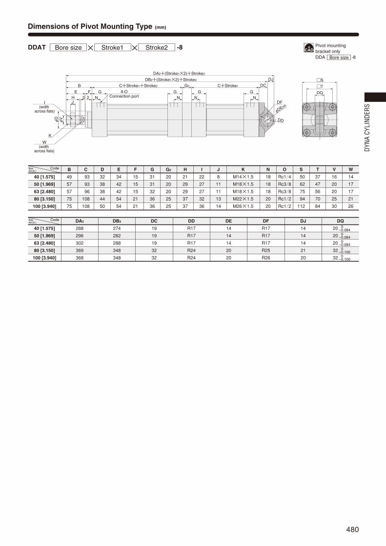
480
G GF
B
φV
φD
23 NG
N N NG 4-O
Connection port
G2 C+Stroke1
DB2+(Stroke1×2)+Stroke2
DA2+(Stroke1×2)+Stroke2
JH
E
C+Stroke1+Stroke2
DQ
T
S
φDEH9
DD
DF
DC
DJ
K
(width across flats)
W
(width across flats)
I
40 [1.575]
50 [1.969]
63 [2.480]
80 [3.150]
100 [3.940]
B
49
57
57
75
75
C
93
93
96
108
108
D
32
38
38
44
50
E
34
42
42
54
54
F
15
15
15
21
21
G
31
31
32
36
36
H
21
29
29
37
37
I
22
27
27
32
36
J
8
11
11
13
14
K
M14×1.5
M18×1.5
M18×1.5
M22×1.5
M26×1.5
N
18
18
18
20
20
O
Rc1/4
Rc3/8
Rc3/8
Rc1/2
Rc1/2
S
50
62
75
94
112
T
37
47
56
70
84
V
16
20
20
25
30
W
14
17
17
21
26
Code
40 [1.575]
50 [1.969]
63 [2.480]
80 [3.150]
100 [3.940]
DA2
288
296
302
369
368
DB2
274
282
288
348
348
DC
19
19
19
32
32
DD
R17
R17
R17
R24
R24
DE
14
14
14
20
20
DF
R17
R17
R17
R25
R26
DJ
14
14
14
21
20
DQ
20
20
20
32
32
–0–0.084–0–0.084–0–0.084–0–0.100–0–0.100
Code
DDAT -8×Bore size Stroke2× Stroke1
Dimensions of Pivot Mounting Type (mm)
G2
20
20
20
25
25
Pivot mounting bracket onlyDDA -8Bore size
Bore mm [in.]
Bore mm [in.]
DYNA
CYL
INDE
RS
474_481ダイナシリンダ_ENG 07.8.25 11:13 AM ページ480

481
40 [1.575]
50 [1.969]
63 [2.480]
80 [3.150]
100 [3.940]
B
49
57
57
75
75
A2
257
265
271
318
318
C
93
93
96
108
108
D
32
38
38
44
50
E
34
42
42
54
54
F
15
15
15
21
21
G
31
31
32
36
36
H
21
29
29
37
37
I
22
27
27
32
36
J
8
11
11
13
14
K
M14×1.5
M18×1.5
M18×1.5
M22×1.5
M26×1.5
N
18
18
18
20
20
O
Rc1/4
Rc3/8
Rc3/8
Rc1/2
Rc1/2
R
2
2
2
2
2
S
50
62
75
94
112
T
37
47
56
70
84
V
16
20
20
25
30
W
14
17
17
21
26
Code G2
20
20
20
25
25
HF
HE
HRHQ
HI
HJ
HT
4‐φHP
φEPe9
/H9
HB
HD
HA
G GF
B
φV
φD
φD
23 N
R
G
N N N
G
G2 C+Stroke1
A2+(Stroke1×2)+Stroke2
JH
E
C+Stroke1+Stroke2
EC
EEEG EGEB
φE
Pe9
ED
TS
I
K
(width across flats)
W
4-OConnection port
ET
EA+(Stroke1+Stroke2)/2
ER
Dimensions of Trunnion Type (mm)
40 [1.575]
50 [1.969]
63 [2.480]
80 [3.150]
100 [3.940]
EA
95.5
103.5
105
129
129
EB
113
126
138
164
182
EC
60
72
87
105
129
ED
30
30
40
40
44
EE
63
76
88
114
132
EG
25
25
25
25
25
EP
25
25
25
25
25
ER
R1.6
R1.6
R1.6
R1.6
R2
ET
30
30
30
35
40
Code
DDAT -11×Bore size Stroke2× Stroke1
40 [1.575]
50 [1.969]
63 [2.480]
80 [3.150]
100 [3.940]
HA
111
111
111
121
121
HB
80
80
80
85
85
HD
R22
R22
R22
R22
R22
HE
109
122
134
160
178
HF
86
99
111
137
155
HI
80
86
93.5
122.5
134.5
HJ
50
50
50
70
70
HP
12(Thru hole)
12(Thru hole)
12(Thru hole)
14(Thru hole)
14(Thru hole)
HQ
23
23
23
23
23
HR
2
2
2
2
2
HT
14
14
14
14
14
EP
25
25
25
25
25
Code
DDATWith Supporting Brackets -11-11T×Bore size Stroke2× Stroke1
Trunnion bracket onlyDDA -11Bore size
Trunnion supportingbracket onlyDDA -11TBore size
Bore mm [in.]
Bore mm [in.]
Bore mm [in.]
474_481ダイナシリンダ_ENG 07.8.25 11:13 AM ページ481

482
Symbol
Specifications
Operation type
Media
Mounting type
Operating pressure range MPa [psi.]
Proof pressure MPa [psi.]
Operating temperature range °C [°F]
Operating speed range mm/s [in./sec.]
Cushion
Cushion stroke mm [in.]
Lubrication
Port size Rc
Double acting type
Air
Basic type, Foot type, Axial foot type, Flange type, Trunnion type
0.05~0.7 [7~102]
1.05 [152]
―10~70 [14~158] (Freezing prohibited, With sensor is 0~60 [32~140].)
30~700 [1.2~27.6]
Variable cushion at both ends of stroke (applied to each cylinder)
16 [0.630]
Not required (If lubrication is required, use Turbine Oil Class 1 (ISO VG32) or equivalent.)
25 [0.984]
Bore size mm [in.]Item 40 [1.575] 50 [1.969] 63 [2.480] 80 [3.150] 100 [3.940]
20 [0.787]
1/4 3/8 1/2
Mounting typeBlank Basic type1 Foot mounting type2 Axial foot mounting type3 Flange mounting type
11 Trunnion type11-11T Trunnion type (with supporting brackets)Mounting brackets are already assembled at
shipping.Orders for mounting brackets only are also accepted.
Aboout stroke 1 and stroke 2Stroke 1 is the stroke of cylinder 1.Stroke 2 is the stroke of cylinder 2.
mm
Boresize Standard strokes
Maximum availablestroke
(Stroke1+Stroke2)
800
1000
1000
50, 75, 100, 150, 200, 250, 300, 350, 400, 450, 500
50, 75, 100, 150, 200, 250, 300, 350, 400, 450
50, 75, 100, 150, 200, 250, 300, 350, 400, 450, 500
600, 700
40
50
63
80
100
Order Codes
Bore Size and Stroke
Bore size×
Stroke 1×
Stroke 2
63×100×50 -- - -
Stroke2
Cylinder2 Cylinder1
Stroke1
DDA
Cylinder specificationW Dual stroke cylinderJW Dual stroke cylinder with bellows
Types of bellowsJT Nylon tarpaulin (~80˚C [176˚F])JC Chloroprene (~100˚C [212˚F])JK Conex (~200˚C [392˚F])JA Alumix (~250˚C [482˚F])Mounted on both sides.Conex is a registered trademark of Teijin, Inc.The temperatures shown are the bellows’
own durable temperatures, and are nottemperatures for cylinder use.
DYNA CylinderBasic model
DYNA DUAL STROKECYLINDERS
Remarks:1. Stroke tolerance; Strokes of 250 or less:
Strokes of 251~1000: 2. The table to the left applies to both stroke 1 and stroke 2.
However, do not let (stroke 1 + stroke 2) exceed the maximum stroke.3. For non-standard strokes, consult us.4. For the maximum available stroke with bellows specification,
see p.538.
+10
+0.039in.+0.039in.[ ]
+1.5+0
+0.059in.+0.059in.[ ]
Sensor switch (For cylinder with magnet)ZC130 2-lead wire Solid state type with indicator lamp DC10~28VZC153 3-lead wire Solid state type with indicator lamp DC4.5~28VCS5T 2-lead wire Reed switch type without indicator lamp DC5~28V
AC85~115VCS11T 2-lead wire Reed switch type with indicator lamp DC10~28VCS2F DIN type Reed switch type with indicator lamp AC85~230VCS3F DIN type Reed switch type with indicator lamp DC10~30VCS4F DIN type Reed switch type with indicator lamp DC10~30VCS5F DIN type Reed switch type without indicator lamp DC3~30VFor mounting location of sensor switch, see p.534.CSF comes with a DIN connector. All others are grommet type.Orders for sensor switches only are also accepted.
Rod end accessoryBlank No rod end accessoryY With Y type knuckle (with pin)I With I type knuckleRod end accessory for one side is included at shipping.
If required for both sides, order separately.For order code, see p.538.
For the cylinder joint and cylinder rod end, see p.1568.Orders for rod end accessories only are also accepted.For dimensions of rod end accessories, see p.537.
( )Lead wire length
Applicable only toZC,CST types
A : 1000mm [39in.]B : 3000mm [118in.]
Number of sensor switches1 With 1 sensor switch2 With 2 sensor switches
n With n sensor switches… …
DYNA
CYL
INDE
RS
482_487ダイナシリンダ_ENG 07.8.25 11:15 AM ページ482

483
kg [lb.]
Parts Rod seal
2
Piston seal
2
Cushion seal
4
Tube gasket
4
Cushion gasket
4QuantityBore size mm
Inner Construction and Major Parts
Seals
40
50
63
80
100
DRP16
DRP20
DRP20
DRP25
DRP30
PWP40N
PWP50N
PWP63N
PWP80N
PWP100N
CPF20
CPF24
CPF24
CPF30
CPF35
1.5×40
1.5×50
1.5×63
1.5×80
1.5×100
S5
S6
S6
S6
S6
Bore sizemm [in.]
Zero stroke mass Additional mass foreach 1mm
[0.0394in.] stroke
Mass of 1 sensor switch [with holder] Mass of 1 knuckleY type knuckle
(with pin) I type knuckleZCCST Note2 CSFBasic type Foot mounting type Axial foot
mounting type Flange mounting type Trunnion type Trunnion type(w. supporting bkt.)
40 [1.575]
50 [1.969]
63 [2.480]
80 [3.150]
100 [3.940]
Mass
Remark: Items marked with a star () are available as repair kits.Order codes: For dual stroke cylinders…SRK-NDDAW
1.32 [2.91]
2.08 [4.59]
2.78 [6.13]
4.74 [10.45]
6.02 [13.27]
1.45 [3.20]
2.25 [4.96]
3.01 [6.64]
5.12 [11.29]
6.49 [14.31]
1.52 [3.35]
2.40 [5.29]
3.30 [7.28]
5.59 [12.33]
7.30 [16.10]
1.69 [3.73]
2.47 [5.45]
3.31 [7.30]
6.34 [13.98]
8.24 [18.17]
1.80 [3.97]
2.63 [5.80]
3.48 [7.67]
5.90 [13.01]
7.55 [16.65]
2.30 [5.07]
3.13 [6.90]
3.98 [8.78]
6.62 [14.60]
8.27 [18.24]
0.00300 [0.00662]
0.00428 [0.00944]
0.00515 [0.01136]
0.00834 [0.01839]
0.01061 [0.02340]
0.04 [0.09]
0.04 [0.09]
0.05[0.11]
0.06 [0.13]
0.27 [0.60]
0.34 [0.75]
0.34 [0.75]
0.87 [1.92]
1.47 [3.24]
0.16 [0.35]
0.21 [0.46]
0.21 [0.46]
0.62 [1.37]
1.24 [2.73]
Notes: 1. Applicable to both stroke 1 and stroke 2.2. For lead wire length A (1000mm [39in.]).
Calculation example: For foot mounting type with bore size of 50mm, and stroke 1 of 100mm and stroke 2of 50mm, 2.25+(0.00428×100)+(0.00428×50)=2.892kg [6.377lb.]
t!0 y e!5!8o !1w!9 qir @1u!7 !4!6
!3@0!2
Operation of dual stroke cylindersDual Stroke Cylinders are a set of 2 cylinders connected back to back.The cylinder body can be secured in place and each stroke can becontrolled separately. It can also be used to obtain 2-stage or 3-stagestrokes by securing the piston rod on one side in place.
The rods retract stroke 1 and stroke 2 independentlywhen air is supplied from Ports A and D.
The rod moves stroke 1 when air is supplied fromPorts B and D.
The rod moves stroke 2 when air is supplied fromPorts A and C.
The rod moves stroke 1 and stroke 2 when air issupplied from Ports B and C.
D C B A
D C B A
D C B A
D C B A
Cylinder2 Cylinder1
Stroke1
Stroke2
Stroke2 Stroke1
Parts
Cylinder tube
Piston rod
Tie rod
Rod cover
Head cover
Spacer
Rod bushing
Keep ring
Piston
Wear ring
Magnet
Cushion needle
Snap ring
Tie rod nut R
Materials
Aluminum alloy
Carbon steel for machine structural use
Carbon steel for machine structural use
Aluminum die-casting
Aluminum die-casting
Aluminum alloy
Oil impregnated sintered copper alloy
Aluminum alloy
Aluminum alloy
Plastic
Rubber magnet
Carbon steel for machine structural use
Spring steel
Rolled steel for general structural use
Major Parts and Materials
Parts
Tie rod nut H
Rod end nut
Rod seal
Piston seal
Cushion seal
Cushion gasket
Tube gasket
Foot mounting bracket
Axial foot mounting bracket
Flange mounting bracket
Trunnion bracket
Trunnion supporting bracket
Knuckles
Materials
Chrome-molybdenum steel
Rolled steel for general structural use
Synthetic rubber (NBR)
Synthetic rubber (NBR)
Synthetic rubber (NBR)
Synthetic rubber (NBR)
Synthetic rubber (NBR)
Rolled steel for general structural use
Cast iron
Rolled steel for general structural use
Cast iron
Cast iron
Cast iron
No. No.
q
w
e
r
t
y
u
i
o
!0
!1
!2
!3
!4
q
w
e
r
t
y
u
i
o
!0
!1
!2
!3
!4
!5
!6
!7
!8
!9
@0
@1
―
―
―
―
―
―
!5
!6
!7
!8
!9
@0
@1
―
―
―
―
―
―
Bore size
482_487ダイナシリンダ_ENG 07.8.25 11:15 AM ページ483

484
G G
φV
φD
T
S
K
4×2‐L
G
N
G
N
P
4-OConnection port
φV
φD
(width across flats)K
P N N
P P
M
M
Q
MQ
Q
MQ
C+Stroke2
2×C+Stroke1+Stroke2+5
5
4-Cushion needle
I
W(width across flats)
B
FE
23
J
H
C+Stroke1
A3+Stroke1+Stroke2
B
F E
2 3
J
H
W
Dimensions of Basic Type (mm)
DDAW ×Bore size Stroke1 × Stroke2
A3Code
40 [1.575]
50 [1.969]
63 [2.480]
80 [3.150]
100 [3.940]
289
305
311
371
371
B
49
57
57
75
75
C
93
93
96
108
108
D
32
38
38
44
50
E
34
42
42
54
54
F
15
15
15
21
21
G
31
31
32
36
36
H
21
29
29
37
37
I
22
27
27
32
36
J
8
11
11
13
14
K
M14×1.5
M18×1.5
M18×1.5
M22×1.5
M26×1.5
L
M6×1 Depth 14
M6×1 Depth 14
M8×1.25 Depth 14
M10×1.5 Depth 15
M10×1.5 Depth 15
NCode
40 [1.575]
50 [1.969]
63 [2.480]
80 [3.150]
100 [3.940]
18
18
18
20
20
O
Rc1/4
Rc3/8
Rc3/8
Rc1/2
Rc1/2
W
14
17
17
21
26
25.5
24
25
29
29
P
10
12
12
16
18
Q
50
62
75
94
112
S
37
47
56
70
84
T
16
20
20
25
30
VM
4
7
8
11
12
DDAW Bore size
Bore mm [in.]
Bore mm [in.]
DYNA
CYL
INDE
RS
482_487ダイナシリンダ_ENG 07.8.25 11:15 AM ページ484

485
φV
AB
AGAD
AB
AG AD
AE
φV
AF
AS
AH
AT
G GT
S
GG
C+Stroke2
2×C+Stroke1+Stroke2+5
5
I
B
FE
23 N N N N
J
H
C+Stroke1
A3+Stroke1+Stroke2
AC3+Stroke1+Stroke2
AA3+Stroke1+Stroke2
B
F E
2 3
J
H
K
(width across flats)
W K
(width across flats)
W
4-OConnection port
Z
Viewed from Z
AP1
AP
2Dimensions of Foot Mounting Type (mm)
DDAW ×Bore size Stroke1 × Stroke2
Code
40 [1.575]
50 [1.969]
63 [2.480]
80 [3.150]
100 [3.940]
AA3
263
271
285
313
313
AB
25.5
29
26
45
45
AC3
238
247
259
281
281
AD
12.5
12
13
16
16
AE
57
68
80
97
112
AF
36
47
56
70
84
AG
23.5
28
31
30
30
AH
30
36.5
41
49
57
AP1
11
11
11
14
14
AP2
13
13
13
16
16
AS
55
67.5
78.5
96
113
AT
3.2
3.2
3.2
4
4
-1
φV
φV
FB FB
FGFD
FE
FQ
FF
FS
FH
FRFT
4-φFP
G GT
S
GG
C+Stroke2
2×C+Stroke1+Stroke2+5
5
I
B
FE
23 N N N N
J
H
C+Stroke1
A3+Stroke1+Stroke2
FC3+Stroke1+Stroke2
FA3+Stroke1+Stroke2
B
F E
2 3
J
H
K
(width across flats)
W
K
(width across flats)
WFG FD
4-OConnection port
Dimensions of Axial Foot Mounting Type (mm)
DDAW ×Bore size Stroke1 × Stroke2
Code
40 [1.575]
50 [1.969]
63 [2.480]
80 [3.150]
100 [3.940]
FA3
217
221
231
263
271
FB
59
67
67
88
88
FC3
171
171
177
195
195
FD
23
25
27
34
38
FE
92
105
117
147
168
FF
70
83
95
121
140
FG
14
14
14
18
18
FH
25
31
38
47
57
FP
12
12
12
14
14
FQ
58
68
84
104
120
FR
16
17
22
28
30
FS
50
62
75.5
94
113
FT
8
9
9
13
14
-2
A3
289
305
311
371
371
B
49
57
57
75
75
C
93
93
96
108
108
E
34
42
42
54
54
F
15
15
15
21
21
G
31
31
32
36
36
H
21
29
29
37
37
I
22
27
27
32
36
J
8
11
11
13
14
K
M14×1.5
M18×1.5
M18×1.5
M22×1.5
M26×1.5
N
18
18
18
20
20
S
50
62
75
94
112
T
37
47
56
70
84
V
16
20
20
25
30
W
14
17
17
21
26
Code
40 [1.575]
50 [1.969]
63 [2.480]
80 [3.150]
100 [3.940]
A3
289
305
311
371
371
B
49
57
57
75
75
C
93
93
96
108
108
E
34
42
42
54
54
F
15
15
15
21
21
G
31
31
32
36
36
H
21
29
29
37
37
I
22
27
27
32
36
J
8
11
11
13
14
K
M14×1.5
M18×1.5
M18×1.5
M22×1.5
M26×1.5
N
18
18
18
20
20
O
Rc1/4
Rc3/8
Rc3/8
Rc1/2
Rc1/2
S
50
62
75
94
112
T
37
47
56
70
84
V
16
20
20
25
30
W
14
17
17
21
26
Code
40 [1.575]
50 [1.969]
63 [2.480]
80 [3.150]
100 [3.940]
O
Rc1/4
Rc3/8
Rc3/8
Rc1/2
Rc1/2
Foot mounting bracket onlyDDA -1Bore size
Axial foot mountingbracket onlyDDA -2Bore size
Bore mm [in.]
Bore mm [in.]
Bore mm [in.]
Bore mm [in.]
482_487ダイナシリンダ_ENG 07.8.25 11:15 AM ページ485
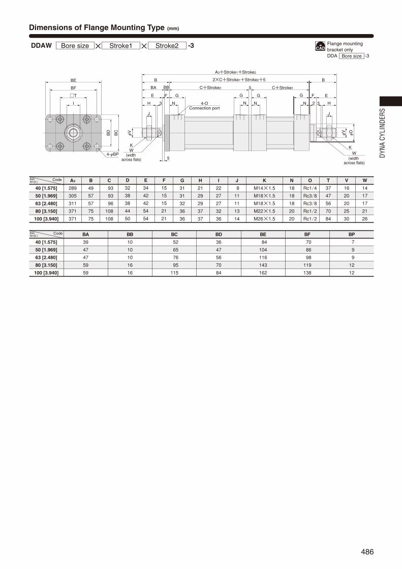
486
φV
φV
φD
BE
BF
BC
BD
4-φBP
G GT GG
C+Stroke2
2×C+Stroke1+Stroke2+5
5
I
B
BBBA
J
5
H 3 N N N N
C+Stroke1
A3+Stroke1+Stroke2
B
F EE F
2 3
J
H
K
(width across flats)
WK
(width across flats)
W
4-OConnection port
Dimensions of Flange Mounting Type (mm)
DDAW ×Bore size Stroke1 × Stroke2
Code
40 [1.575]
50 [1.969]
63 [2.480]
80 [3.150]
100 [3.940]
BA
39
47
47
59
59
BB
10
10
10
16
16
BC
52
65
76
95
115
BD
36
47
56
70
84
BE
84
104
116
143
162
BF
70
86
98
119
138
BP
7
9
9
12
12
-3
A3
289
305
311
371
371
B
49
57
57
75
75
C
93
93
96
108
108
G
31
31
32
36
36
H
21
29
29
37
37
I
22
27
27
32
36
J
8
11
11
13
14
K
M14×1.5
M18×1.5
M18×1.5
M22×1.5
M26×1.5
N
18
18
18
20
20
D
32
38
38
44
50
E
34
42
42
54
54
F
15
15
15
21
21
T
37
47
56
70
84
V
16
20
20
25
30
W
14
17
17
21
26
Code
40 [1.575]
50 [1.969]
63 [2.480]
80 [3.150]
100 [3.940]
O
Rc1/4
Rc3/8
Rc3/8
Rc1/2
Rc1/2
Flange mounting bracket onlyDDA -3Bore size
Bore mm [in.]
Bore mm [in.]
DYNA
CYL
INDE
RS
482_487ダイナシリンダ_ENG 07.8.25 11:15 AM ページ486

487
φV
φD
φV
φD
ET
Stroke2
2EA+
G GGG
C+Stroke2
2×C+Stroke1+Stroke2+5
5
B
FE
23
J
H
C+Stroke1
A3+Stroke1+Stroke2
B
F E
2 3N
J
HNNN
K
(width across flats)W
K
(width across flats)
W
4-OConnection port
EEEG EG
EB
T
S
I
EC
ED
φE
Pe9
ER
Dimensions of Trunnion Type (mm)
DDAW ×Bore size Stroke1 × Stroke2
Code
40 [1.575]
50 [1.969]
63 [2.480]
80 [3.150]
100 [3.940]
EA
195.5
103.5
105.5
129.5
129.5
EB
113
126
138
164
182
EC
60
72
87
105
129
ED
30
30
40
40
44
EE
63
76
88
114
132
EG
25
25
25
25
25
EP
25
25
25
25
25
ER
R1.6
R1.6
R1.6
R1.6
R2
ET
30
30
30
35
40
-11
HF
HE
4‐φHP
HRHQ
HJ
HT
φEPe9/H9
HI
HB
HD
HA
DDAWWith Supporting Brackets ×Bore size Stroke1 × Stroke2
HACode
40 [1.575]
50 [1.969]
63 [2.480]
80 [3.150]
100 [3.940]
111
111
111
121
121
HB
80
80
80
85
85
HD
R22
R22
R22
R22
R22
HE
109
122
134
160
178
HF
86
99
111
137
155
HI
80
86
93.5
122.5
134.5
HJ
50
50
50
70
70
HP
12(Thru hole)
12(Thru hole)
12(Thru hole)
14(Thru hole)
14(Thru hole)
HQ
23
23
23
23
23
HR
2
2
2
2
2
HT
14
14
14
14
14
EP
25
25
25
25
25
-11-11T
A3
289
305
311
371
371
B
49
57
57
75
75
C
93
93
96
108
108
E
34
42
42
54
54
F
15
15
15
21
21
G
31
31
32
36
36
H
21
29
29
37
37
I
22
27
27
32
36
J
8
11
11
13
14
K
M14×1.5
M18×1.5
M18×1.5
M22×1.5
M26×1.5
N
18
18
18
20
20
S
50
62
75
94
112
T
37
47
56
70
84
V
16
20
20
25
30
W
14
17
17
21
26
Code
40 [1.575]
50 [1.969]
63 [2.480]
80 [3.150]
100 [3.940]
O
Rc1/4
Rc3/8
Rc3/8
Rc1/2
Rc1/2
D
32
38
38
44
50
Trunnion bracket onlyDDA -11Bore size
Trunnion supportingbracket onlyDDA -11TBore size
Bore mm [in.]
Bore mm [in.]
Bore mm [in.]
482_487ダイナシリンダ_ENG 07.8.25 11:15 AM ページ487

488
Mounting typeBlank Basic type1 Foot mounting type2 Axial foot mounting type3 Rod side flange mounting type
11 Trunnion type11-11T Trunnion type (with supporting brackets)Mounting brackets are already assembled at
shipping.Orders for mounting brackets only are also
accepted.
mm
Bore
sizeStandard strokes
Maximum available stroke
700
900
50, 75, 100, 150, 200, 250, 300, 350, 400
450, 500, 600, 700
50, 75, 100, 150, 200, 250, 300, 350, 400
450, 500, 600, 700, 800, 900
40
50
63
80
100
Order Codes
Bore Size and Stroke
Symbols
Push side stroke adjusting type Pull side stroke adjusting type
Push side stroke adjusting type Pull side stroke adjusting type
Specifications
Bore size×
Stroke
DDA 50×100 -- - -
Operation type
Media
Mounting type
Stroke adjusting rangemm [in.]
Operating pressure range MPa [psi.]
Proof pressure MPa [psi.]
Operating temperature range °C [°F]
Operating speed rangemm/s [in./sec.]
Cushion
Cushion stroke mm [in.]
Lubrication
Port size Rc
Double acting type with stroke adjusting mechanism
Air
Basic type, Foot type, Axial foot type, Rod side flange type, Trunnion type
-50~0 [-1.969~0] (To the specified stroke)
-60~0 [-2.362~0] (To the specified stroke)
0.05~1.0 [7~145]
1.5 [218]
―10~70 [14~158] (Freezing prohibited, With sensor is 0~60 [32~140].)
50~700 [2.0~27.6]Note 1
30~700 [1.2~27.6]Note 2
20 [0.787]16 [0.630]
Not required (If lubrication is required, use Turbine Oil Class 1 (ISO VG32) or equivalent.)
Rod cover side: Variable cushion Head cover side: NoneNote 3
Head cover side: Variable cushion Rod cover side: Rubber bumperNote 3
1/4
Notes : 1. For pull side. For push side (Stroke adjusting side) 50~500mm/s [2.0~19.7in./sec.] for φ40: adjustment 10mm [0.394in.] or less, for φ50, 63: adjustment 15mm [0.591in.] or less, for φ80, 100: adjustment 20mm [0.787in.] or less.Notes : 1. 50~200mm/s [2.0~7.9in./sec.] for φ40: adjustment 10mm [0.394in.] or more, for φ50, 63: adjustment 15mm [0.591in.] or more, for φ80, 100: adjustment 20mm [0.787in.] or more.Notes : 2. For push side. For pull side (Stroke adjusting side) 30~500mm/s [1.2~19.7in./sec.] for φ40: adjustment 10mm [0.394in.] or less, for φ50, 63: adjustment 15mm [0.591in.] or less, for φ80, 100: adjustment 20mm [0.787in.] or less.Notes : 2. 30~150mm/s [1.2~5.9in./sec.] for φ40: adjustment 10mm [0.394in.] or more, for φ50, 63: adjustment 15mm [0.591in.] or more, for φ80, 100: adjustment 20mm [0.787in.] or more.Notes : 3. The cushion seals are mounted on both sides of the cover.
3/8 1/2
25 [0.984]
40 [1.575] 50 [1.969] 63 [2.480] 80 [3.150] 100 [3.940]Bore size mm [in.]Item
Rod end accessoryBlank No rod end accessoryY With Y type knuckle (with pin)I With I type knuckleFor the cylinder joint and cylinder rod end, see p.1568.Orders for rod end accessories only are also accepted.For dimensions of rod end accessories, see p.537.DYNA Cylinder
Basic model
mm
Bore
sizeStandard strokes
Maximum available stroke
1000
1500
50, 75, 100, 150, 200, 250, 300, 350, 400, 450, 500, 600, 700, 800
50, 75, 100, 150, 200, 250, 300, 350, 400
450, 500, 600, 700, 800, 900, 1000
40
50
63
80
100
Push side stroke
Pull side stroke
Push side stroke
Pull side stroke
Push side stroke
Pull side stroke
Types of bellowsJT Nylon tarpaulin (~80°C [176°F])JC Chloroprene (~100°C [212°F])JK Conex (~200°C [392°F]JA Alumix (~250°C [482°F])Conex is a registered trademark of Teijin, Inc.The temperatures shown are the bellows’ own
durable temperatures, and are nottemperatures for cylinder use.
Push Side Stroke Adjusting TypePull Side Stroke Adjusting Type
DYNA STROKE ADJUSTINGCYLINDERS
Remarks: 1. Stroke tolerance; Strokes of 250 or less:
Strokes of 251~1000: 2. For non-standard strokes, consult us.
+10
+0.039in.+0.039in.[ ]
+1.5+0
+0.059in.+0.059in.[ ]
Remarks: 1. Stroke tolerance; Strokes of 250 or less: , strokes of 251~1000: , and strokes of 1001 or more: .
2. For non-standard strokes, consult us.3. For the maximum available stroke with bellows specification, see p.538.
+10
+0.039in.+0.039in.[ ]
+1.5+0
+0.059in.+0.059in.[ ] +2.0
+0+0.079in.+0.079in.[ ]
Cylinder specificationP Push side stroke adjusting cylinderE Pull side stroke adjusting cylinderJP Push side stroke adjusting cylinder with bellowsEJ Pull side stroke adjusting cylinder with bellows
Sensor switch (For cylinder with magnet)ZC130 2-lead wire Solid state type with indicator lamp DC10~28VZC153 3-lead wire Solid state type with indicator lamp DC4.5~28VCS5T 2-lead wire Reed switch type without indicator lamp DC5~28V
AC85~115VCS11T 2-lead wire Reed switch type with indicator lamp DC10~28VCS2F DIN type Reed switch type with indicator lamp AC85~230VCS3F DIN type Reed switch type with indicator lamp DC10~30VCS4F DIN type Reed switch type with indicator lamp DC10~30VCS5F DIN type Reed switch type without indicator lamp DC3~30VFor mounting location of sensor switch, see p.534.CSF comes with a DIN connector. All others are grommet type.
( )Lead wire length
Applicable only toZC,CST types
A : 1000mm [39in.]B : 3000mm [118in.]
Number of sensor switches1 With 1 sensor switch2 With 2 sensor switches
n With n sensor switches… …
DYNA
CYL
INDE
RS
488_491ダイナシリンダ_ENG 07.8.25 11:19 AM ページ488

489
Inner Construction and Major Parts
@3!7 !8 w @0 !9 @2o!1 t@5!3i !2@9@6 !0
qe
ur @8y@4 !6@1
!5@7!4
Instructions for stroke adjustmentStroke adjusting is performed by rotating the adjusting stopper (push side !9) or stroke adjusting screw (pull side i).After completing stroke adjustment, secure the adjusting stopper or adjusting screw in place with a lock nut.If mounting a sensor switch, move the mounting location of the sensor switch along the length of the adjusted stroke.
Push side stroke adjusting type
Pull side strokeadjusting type
Major Parts and Materials
@3@5 t@7!3!7 !2 @0u !8 oi@6q !1e@3 w!0r @5y@1 !6!9
!5@4!4
Cylinder tube
Piston rod
Tie rod
Rod cover
Head cover
Rod bushing
Housing
Adjusting screw
Button bolt
Keep ring
Piston
Wear ring
Magnet
Cushion needle
Snap ring
Tie rod nut R
Tie rod nut H
Lock nut
Rod end nut
Seal washer
Rod seal
Piston seal
Cushion seal
Cushion gasket
Tube gasket
Piston gasket
Housing gasket
Parts Materials
Aluminum alloy
Carbon steel for machine structural use
Carbon steel for machine structural use
Aluminum die-casting
Aluminum die-casting
Oil impregnated sintered copper alloy
Carbon steel for machine structural use
Carbon steel for machine structural use
Chrome-molybdenum steel
Aluminum alloy
Aluminum alloy
Plastic
Rubber magnet
Carbon steel for machine structural use
Spring steel
Rolled steel for general structural use
Chrome-molybdenum steel
Rolled steel for general structural use
Rolled steel for general structural use
Nitrile rubber with metal ring
Synthetic rubber (NBR)
Synthetic rubber (NBR)
Synthetic rubber (NBR)
Synthetic rubber (NBR)
Synthetic rubber (NBR)
Synthetic rubber (NBR)
Synthetic rubber (NBR)
No.
q
w
e
r
t
y
u
i
o
!0
!1
!2
!3
!4
!5
!6
!7
!8
!9
@0
@1
@2
@3
@4
@5
@6
@7
q
w
e
r
t
y
u
i
o
!0
!1
!2
!3
!4
!5
!6
!7
!8
!9
@0
@1
@2
@3
@4
@5
@6
@7
Cylinder tube
Piston rod
Tie rod
Rod cover
Rod cover
Rod bushing
Keep ring
Piston
Piston
Split ring
(Detent) pin
Wear ring
Magnet
Cushion needle
Snap ring
Tie rod nut R
Tie rod nut H
Stopper plate
Adjusting stopper
Rubber bumper
Rod end nut
Lock nut
Button bolt
Rod seal
Piston seal
Cushion seal
Cushion gasket
Tube gasket
Piston gasket
Parts Materials
Aluminum alloy
Carbon steel for machine structural use
Carbon steel for machine structural use
Aluminum die-casting
Aluminum die-casting
Oil impregnated sintered copper alloy
Aluminum alloy
Aluminum alloy
Aluminum alloy
Carbon steel for machine structural use
Carbon steel for machine structural use
Plastic
Rubber magnet
Carbon steel for machine structural use
Spring steel
Rolled steel for general structural use
Chrome-molybdenum steel
Carbon steel for machine structural use
Carbon steel for machine structural use
Urethane rubber
Rolled steel for general structural use
Rolled steel for general structural use
Chrome-molybdenum steel
Synthetic rubber (NBR)
Synthetic rubber (NBR)
Synthetic rubber (NBR)
Synthetic rubber (NBR)
Synthetic rubber (NBR)
Synthetic rubber (NBR)
No.
q
w
e
r
t
y
u
i
o
!0
!1
!2
!3
!4
!5
!6
!7
!8
!9
@0
@1
@2
@3
@4
@5
@6
@7
@8
@9
q
w
e
r
t
y
u
i
o
!0
!1
!2
!3
!4
!5
!6
!7
!8
!9
@0
@1
@2
@3
@4
@5
@6
@7
@8
@9
PartsRodseal
Pistonseal
Cushionseal
2 1 2QuantityBore mm
Seals
40
50
63
80
100
DRP16
DRP20
DRP20
DRP25
DRP30
PWP40N
PWP50N
PWP63N
PWP80N
PWP100N
CPF20
CPF24
CPF24
CPF30
CPF35
Tube gasket
2
1.5×40
1.5×50
1.5×63
1.5×80
1.5×100
Cushiongasket
2
S5
S6
S6
S6
S6
Pistongasket
1
P12
P16
P16
P21
P25
Push side stroke adjusting type
PartsRodseal
Pistonseal
Cushionseal
1 1 2QuantityBore mm
40
50
63
80
100
DRP16
DRP20
DRP20
DRP25
DRP30
PWP40N
PWP50N
PWP63N
PWP80N
PWP100N
CPF20
CPF24
CPF24
CPF30
CPF35
Tube gasket
2
1.5×40
1.5×50
1.5×63
1.5×80
1.5×100
Cushiongasket
2
S5
S6
S6
S6
S6
Pistongasket
1
S10
S14
S14
S18
S18
Housing gasket
1
S26
S32
S32
S38
S38
Sealwasher
1
DT1-12
DT1-16
DT1-16
DT1-20
DT1-20
Pull side stroke adjusting type
Push side stroke adjusting type Pull side stroke adjusting type
Remark: Items marked with a star () are available as repair kits. Order codes: For push side stroke adjusting cylinders…SRK-NDDAP Bore size
488_491ダイナシリンダ_ENG 07.8.25 11:19 AM ページ489

490
Push side stroke adjusting type kg [lb.]
Bore sizemm [in.]
Zero stroke mass Additional mass for each 1mm
[0.0394in.] stroke
Mass of 1 sensor switch [with holder] Mass of 1 knuckleY type knuckle
(with pin) I type knuckleZCCST Note CSFBasic type Foot mounting type Axial foot
mounting type Flange mounting type Trunnion type Trunnion type (withsupporting brackets)
40 [1.575]
50 [1.969]
63 [2.480]
80 [3.150]
100 [3.940]
Mass
1.57 [3.46]
2.53 [5.58]
3.38 [7.45]
6.10 [13.45]
8.45 [18.63]
1.70 [3.75]
2.70 [5.95]
3.61 [7.96]
6.48 [14.29]
8.92 [19.67]
1.77 [3.90]
2.85 [6.28]
3.90 [8.60]
6.95 [15.32]
9.73 [21.45]
1.94 [4.28]
2.92 [6.44]
3.91 [8.62]
7.70 [16.98]
10.67 [23.53]
2.05 [4.52]
3.08 [6.79]
4.08 [9.00]
7.26 [16.01]
9.98 [22.01]
2.55 [5.62]
3.58 [7.89]
4.58 [10.10]
7.98 [17.60]
10.70 [23.59]
0.00457 [0.01008]
0.00673 [0.01484]
0.00760 [0.01676]
0.01217 [0.02683]
0.01612 [0.03554]
0.04 [0.09]
0.04 [0.09]
0.05 [0.11]
0.06 [0.13]
0.27 [0.60]
0.34 [0.75]
0.34 [0.75]
0.87 [1.92]
1.47 [3.24]
0.16 [0.35]
0.21 [0.46]
0.21 [0.46]
0.62 [1.37]
1.24 [2.73]
Note: For lead wire length A (1000mm [39in.]). Calculation example: For foot mounting type with bore size of 50mm, and stroke of 100 mm,2.70+(0.00673×100)=3.373kg [7.437lb.]
kg [lb.]
Bore sizemm [in.]
Zero stroke mass Additional mass for each 1mm
[0.0394in.] stroke
Mass of 1 sensor switch [with holder] Mass of 1 knuckleY type knuckle
(with pin) I type knuckleZCCST Note CSFBasic type Foot mounting type Axial foot
mounting type Flange mounting type Trunnion type Trunnion type (withsupporting brackets)
40 [1.575]
50 [1.969]
63 [2.480]
80 [3.150]
100 [3.940]
1.14 [2.51]
1.87 [4.12]
2.54 [5.60]
4.67 [10.30]
6.35 [14.00]
1.27 [2.80]
2.04 [4.50]
2.77 [6.11]
5.05 [11.14]
6.82 [15.04]
1.34 [2.95]
2.19 [4.83]
3.06 [6.75]
5.52 [12.17]
7.63 [16.82]
1.51 [3.33]
2.26 [4.98]
3.07 [6.77]
6.27 [13.83]
8.57 [18.90]
1.62 [3.57]
2.42 [5.34]
3.24 [7.14]
5.83 [12.86]
7.88 [17.38]
2.12 [4.67]
2.92 [6.44]
3.74 [8.25]
6.55 [14.44]
8.60 [18.96]
0.00300 [0.00662]
0.00428 [0.00944]
0.00515 [0.01136]
0.00834 [0.01839]
0.01061 [0.02340]
0.04 [0.09]
0.04 [0.09]
0.05 [0.11]
0.06 [0.13]
0.27 [0.60]
0.34 [0.75]
0.34 [0.75]
0.87 [1.92]
1.47 [3.24]
0.16 [0.35]
0.21 [0.46]
0.21 [0.46]
0.62 [1.37]
1.24 [2.73]
Note: For lead wire length A (1000mm [39in.]). Calculation example: For foot mounting type with bore size of 50mm, and stroke of 100 mm, 2.04+(0.00428×100)=2.468kg [5.442lb.]
Pull side stroke adjusting type
G GF
B
φV
φD
T
S
N N
P P
2-OConnection port
23 2
(width across flats)K
4‐L
MQ
MQ
C+Stroke
(width across flats)I4
K4
(width across flats)
F4
B4+Stroke
E4(After adjustment stroke) Z4
φD
φV
φD
4
A4+(Stroke×2)
2-Cushion needle
I
J J4
H
E
W4
W
Dimensions of Push Side Stroke Adjusting Basic Type (mm)
DDAP ×Bore size Stroke
Code
40 [1.575]
50 [1.969]
63 [2.480]
80 [3.150]
100 [3.940]
A4
254
274
277
321
321
J4
7
10
10
12
12
K
M14×1.5
M18×1.5
M18×1.5
M22×1.5
M26×1.5
K4
M12×1.25
M16×1.5
M16×1.5
M20×1.5
M20×1.5
L
M6×1 Depth 14
M6×1 Depth 14
M8×1.25 Depth 14
M10×1.5 Depth 15
M10×1.5 Depth 15
M
4
7
8
11
12
N
18
18
18
20
20
O
Rc1/4
Rc3/8
Rc3/8
Rc1/2
Rc1/2
P
25.5
24
25
29
29
Q
10
12
12
16
18
S
50
62
75
94
112
T
37
47
56
70
84
V
16
20
20
25
30
W
14
17
17
21
26
W4
27
32
32
41
46
Z4
74
83
83
84
84
B
49
57
57
75
75
B4
112
124
124
138
138
C
93
93
96
108
108
D
32
38
38
44
50
D4
30
36
36
45
50
E
34
42
42
54
54
E4
11
14
14
17
17
F
15
15
15
21
21
F4
25
25
25
35
35
G
31
31
32
36
36
H
21
29
29
37
37
I
22
27
27
32
36
I4
19
22
22
27
27
J
8
11
11
13
14
Code
40 [1.575]
50 [1.969]
63 [2.480]
80 [3.150]
100 [3.940]
DDAP Bore size
Bore mm [in.]
Bore mm [in.]
DYNA
CYL
INDE
RS
488_491ダイナシリンダ_ENG 07.8.25 11:19 AM ページ490

491
φV
(width across flats)
I4
K4(width across flats)
φV
φD
4
G GF
B
T
S
23 2
C+Stroke
F4
B4+Stroke
E4(After adjustment stroke) Z4
A4+(Stroke×2)
I
J J4
H
E
W4
AS
AH
AT
K
(width across flats)
W
AD AG
AA4+Stroke
AB4+StrokeAC4+Stroke
ADAG
AF
AE
AB
N N2-OConnection port
Z
Viewed from ZAP1
AP
2Dimensions of Push Side Stroke Adjusting Foot Mounting Type (mm)
DDAP -1×Bore size Stroke
Code
40 [1.575]
50 [1.969]
63 [2.480]
80 [3.150]
100 [3.940]
Code
40 [1.575]
50 [1.969]
63 [2.480]
80 [3.150]
100 [3.940]
φV
(width across flats)
I4
K4
(width across flats)
φV
φD
4
G GF
B
T
S
23 2
C+Stroke
F4
B4+Stroke
E4(After adjustment stroke) Z4
A4+(Stroke×2)
I
J J4
H
E
W4K
(width across flats)W
FF
FE
FQ
FH
FRFT
FS
4-φFP
FD
FC4+Stroke FB4+Stroke
FA4+Stroke
FB
FG FDFG
N N2-OConnection port
Dimensions of Push Side Stroke Adjusting Axial Foot Mounting Type (mm)
DDAP -2×Bore size Stroke
Code
40 [1.575]
50 [1.969]
63 [2.480]
80 [3.150]
100 [3.940]
254
274
277
321
321
S T
A4
49
57
57
75
75
B
Code
40 [1.575]
50 [1.969]
63 [2.480]
80 [3.150]
100 [3.940]
50
62
75
94
112
37
47
56
70
84
V
16
20
20
25
30
W
14
17
17
21
26
W4
27
32
32
41
46
Z4
74
83
83
84
84
FA4
144
148
155
185
193
FB
59
67
67
88
88
FB4
197
109
109
116
116
FC4
198
198
101
117
117
FD
23
25
27
34
38
FE
92
105
117
147
168
FF
70
83
95
121
140
FG
14
14
14
18
18
FH
25
31
38
47
57
FP
12
12
12
14
14
FQ
58
68
84
104
120
FR
16
17
22
28
30
FS
50
62
75.5
94
113
FT
8
9
9
13
14
B4
112
124
124
138
138
C
93
93
96
108
108
D4
30
36
36
45
50
E
34
42
42
54
54
E4
11
14
14
17
17
F
15
15
15
21
21
F4
25
25
25
35
35
G
31
31
32
36
36
H
21
29
29
37
37
I
22
27
27
32
36
K
M14×1.5
M18×1.5
M18×1.5
M22×1.5
M26×1.5
K4
M12×1.25
M16×1.5
M16×1.5
M20×1.5
M20×1.5
19
22
22
27
27
JI4
8
11
11
13
14
J4
7
10
10
12
12
18
18
18
20
20
N
Rc1/4
Rc3/8
Rc3/8
Rc1/2
Rc1/2
O
A4
254
274
277
321
321
S
50
62
75
94
112
T
37
47
56
70
84
V
16
20
20
25
30
W
14
17
17
21
26
W4
27
32
32
41
46
Z4
74
83
83
84
84
AA4
190
198
209
235
235
AB
25.5
29
26
45
45
AB4
63.5
71
68
73
73
AC4
165
174
183
203
203
AD
12.5
12
13
16
16
AE
57
68
80
97
112
AF
36
47
56
70
84
AG
23.5
28
31
30
30
AH
30
36.5
41
49
57
AP1
11
11
11
14
14
AP2
13
13
13
16
16
AS
55
67.5
78.5
96
113
AT
3.2
3.2
3.2
4
4
B
49
57
57
75
75
B4
112
124
124
138
138
C
93
93
96
108
108
D4
30
36
36
45
50
E
34
42
42
54
54
E4
11
14
14
17
17
F
15
15
15
21
21
F4
25
25
25
35
35
G
31
31
32
36
36
H
21
29
29
37
37
I
22
27
27
32
36
I4
19
22
22
27
27
J
8
11
11
13
14
J4
7
10
10
12
12
K
M14×1.5
M18×1.5
M18×1.5
M22×1.5
M26×1.5
K4
M12×1.25
M16×1.5
M16×1.5
M20×1.5
M20×1.5
N
18
18
18
20
20
O
Rc1/4
Rc3/8
Rc3/8
Rc1/2
Rc1/2
Foot mounting bracket onlyDDA -1Bore size
Axial foot mounting bracket onlyDDA -2Bore size
Bore mm [in.]
Bore mm [in.]
Bore mm [in.]
Bore mm [in.]
488_491ダイナシリンダ_ENG 07.8.25 11:19 AM ページ491

492
φV
5(width across flats)
I4 K4
(width across flats)
D
φV
φD
4
G G
B
2
C+Stroke
F4
B4+Stroke
E4(After adjustment stroke) Z4
A4+(Stroke×2)
J J4
H 3
BA
W4K
(width across flats)
W
BF
BE
T
IB
D
BC
4‐φBP
BB
N N2-OConnection port
Dimensions of Push Side Stroke Adjusting Rod Side Flange Mounting Type (mm)
DDAP -3×Bore size Stroke
Code
40 [1.575]
50 [1.969]
63 [2.480]
80 [3.150]
100 [3.940]
N
A4
254
274
277
321
321
B
49
57
57
75
75
B4
112
124
124
138
138
C
93
93
96
108
108
D4
30
36
36
45
50
E4
11
14
14
17
17
F4
25
25
25
35
35
G
31
31
32
36
36
H
21
29
29
37
37
I
22
27
27
32
36
I4
19
22
22
27
27
J
8
11
11
13
14
J4
7
10
10
12
12
K
M14×1.5
M18×1.5
M18×1.5
M22×1.5
M26×1.5
K4
M12×1.25
M16×1.5
M16×1.5
M20×1.5
M20×1.5
Code
40 [1.575]
50 [1.969]
63 [2.480]
80 [3.150]
100 [3.940]
18
18
18
20
20
O
Rc1/4
Rc3/8
Rc3/8
Rc1/2
Rc1/2
T
37
47
56
70
84
V
16
20
20
25
30
W
14
17
17
21
26
W4
27
32
32
41
46
Z4
74
83
83
84
84
BA
39
47
47
59
59
BB
10
10
10
16
16
BC
52
65
76
95
115
BD
36
47
56
70
84
BE
84
104
116
143
162
BF
70
86
98
119
138
BP
7
9
9
12
12
Flange mounting bracket onlyDDA -3Bore size
Bore mm [in.]
Bore mm [in.]
DYNA
CYL
INDE
RS
492_497ダイナシリンダ_ENG 07.8.25 11:19 AM ページ492

493
φV
φD
(width across flats)I4 K4
(width across flats)
φD
φV
φD
4
G GF
B
23 2
C+Stroke
F4
B4+Stroke
E4(After adjustment stroke) Z4
A4+(Stroke×2)
J J4
H
E
W4K
(width across flats)
W
ET
Stroke2EA+
T
S
I
EEEG EG
EB
EC
ED
φE
Pe9
N N2-OConnection port
ER
Dimensions of Push Side Stroke Adjusting Trunnion Type (mm)
DDAP -11×Bore size Stroke
Code
40 [1.575]
50 [1.969]
63 [2.480]
80 [3.150]
100 [3.940]
254
274
277
321
321
N
A4
49
57
57
75
75
B
112
124
124
138
138
B4
93
93
96
108
108
C
32
38
38
44
50
D
30
36
36
45
50
D4
34
42
42
54
54
E
11
14
14
17
17
E4
15
15
15
21
21
F
25
25
25
35
35
F4
31
31
32
36
36
G
21
29
29
37
37
H
22
27
27
32
36
I
19
22
22
27
27
I4
8
11
11
13
14
J
7
10
10
12
12
J4
M14×1.5
M18×1.5
M18×1.5
M22×1.5
M26×1.5
K
M12×1.25
M16×1.5
M16×1.5
M20×1.5
M20×1.5
K4
Code
40 [1.575]
50 [1.969]
63 [2.480]
80 [3.150]
100 [3.940]
18
18
18
20
20
O
Rc1/4
Rc3/8
Rc3/8
Rc1/2
Rc1/2
S
50
62
75
94
112
T
37
47
56
70
84
V
16
20
20
25
30
W
14
17
17
21
26
W4
27
32
32
41
46
Z4
74
83
83
84
84
EA
95.5
103.5
105
129
129
EB
113
126
138
164
182
EC
60
72
87
105
129
ED
30
30
40
40
44
EE
63
76
88
114
132
EG
25
25
25
25
25
EP
25
25
25
25
25
ER
R1.6
R1.6
R1.6
R1.6
R2
ET
30
30
30
35
40
HF
HE
HRHQ
HJ
HT
4‐φHP
φEPe9
/H9
HI
HB
HD
HA
DDAPWith Supporting Brackets ×Bore size Stroke
HACode
40 [1.575]
50 [1.969]
63 [2.480]
80 [3.150]
100 [3.940]
111
111
111
121
121
HB
80
80
80
85
85
HD
R22
R22
R22
R22
R22
HE
109
122
134
160
178
HF
186
199
111
137
155
HI
80
86
93.5
122.5
134.5
HJ
50
50
50
70
70
12 (Thru hole)
12 (Thru hole)
12 (Thru hole)
14 (Thru hole)
14 (Thru hole)
HP HQ
23
23
23
23
23
HR
2
2
2
2
2
HT
14
14
14
14
14
EP
25
25
25
25
25
-11-11T
Trunnion bracket onlyDDA -11Bore size
Trunnion supportingbracket onlyDDA -11TBore size
Bore mm [in.]
Bore mm [in.]
Bore mm [in.]
492_497ダイナシリンダ_ENG 07.8.25 11:19 AM ページ493

494
G G
C5+Stroke
F
B
φV
φD
T
S
N N
P P
2‐OConnection port
23
W
K4‐L
MQ
MQ
G5 J5
Stroke adjustingrange
A5+Stroke
K5 V5
(width across flats)
2-Cushion needle
I
E
(width across flats)
J
H
B5
Z5
I5
Dimensions of Pull Side Stroke Adjusting Basic Type (mm)
DDAE ×Bore size Stroke
Code
40 [1.575]
50 [1.969]
63 [2.480]
80 [3.150]
100 [3.940]
238
249
252
296
296
A5
49
57
57
75
75
B
82
85
85
91
91
B5
107
107
110
130
130
C5
32
38
38
44
50
D
34
42
42
54
54
E
15
15
15
21
21
F
31
31
32
36
36
G
14
14
14
22
22
G5
21
29
29
37
37
H
22
27
27
32
36
I
19
24
24
30
30
I5
8
11
11
13
14
J
12
15
15
19
19
J5
M14×1.5
M18×1.5
M18×1.5
M22×1.5
M26×1.5
K
M12×1.25
M16×1.5
M16×1.5
M20×1.5
M20×1.5
K5
L
M6×1 Depth 14
M6×1 Depth 14
M8×1.25 Depth 14
M10×1.5 Depth 15
M10×1.5 Depth 15
Code
40 [1.575]
50 [1.969]
63 [2.480]
80 [3.150]
100 [3.940]
4
7
8
11
12
M
18
18
18
20
20
N
Rc1/4
Rc3/8
Rc3/8
Rc1/2
Rc1/2
O
25.5
24
25
29
29
P
10
12
12
16
18
Q
50
62
75
94
112
S
37
47
56
70
84
T
16
20
20
25
30
V
8
11
11
14
14
V5
14
17
17
21
26
W
10
10
10
12
12
Z5
DDAE Bore size
Bore mm [in.]
Bore mm [in.]
DYNA
CYL
INDE
RS
492_497ダイナシリンダ_ENG 07.8.25 11:20 AM ページ494

495
φV
AD AG
AA5+Stroke
AC5+Stroke
ADAG
AF
AE
AB AB5MAX.
G G
C5+Stroke
F
B
T
S
23 N
G5 J5 Stroke adjusting range
A5+Stroke
I
AS
AH
AT
E
J
H N
B5
Z5
K
(width across flats)W
K5
V5
(width across flats)I5
2-OConnection port
Z
Viewed from Z
AP1
AP
2
Dimensions of Pull Side Stroke Adjusting Foot Mounting Type (mm)
DDAE -1×Bore size Stroke
Code
40 [1.575]
50 [1.969]
63 [2.480]
80 [3.150]
100 [3.940]
NCode
40 [1.575]
50 [1.969]
63 [2.480]
80 [3.150]
100 [3.940]
18
18
18
20
20
O
Rc1/4
Rc3/8
Rc3/8
Rc1/2
Rc1/2
S
50
62
75
94
112
T
37
47
56
70
84
V
16
20
20
25
30
V5
8
11
11
14
14
W
14
17
17
21
26
Z5
10
10
10
12
12
AA5
179
187
198
222
222
AB
25.5
29
26
45
45
AB5
58.5
57
54
61
61
AC5
154
163
172
190
190
AD
12.5
12
13
16
16
AE
57
68
80
97
112
AF
36
47
56
70
84
AG
23.5
28
31
30
30
AH
30
36.5
41
49
57
AP1 AP2
11
11
11
14
14
13
13
13
16
16
AS
55
67.5
78.5
96
113
3.2
3.2
3.2
4
4
AT
φV
FD
FC5+Stroke
FA5+Stroke
FB FB5MAX.
FG FDFGFF
FE
FQ
FH
FRF
T
G G
C5+Stroke
F
B
T
S
23 N
G5 J5
A5+Stroke
I
E
J
H N
B5
Z5
FS
K
4-φFP(width across flats)
W
K5
V5
(width across flats)I5
2-OConnection port
Stroke adjusting range
Dimensions of Pull Side Stroke Adjusting Axial Foot Mounting Type (mm)
DDAE -2×Bore size Stroke
Code
40 [1.575]
50 [1.969]
63 [2.480]
80 [3.150]
100 [3.940]
238
249
252
296
296
A5
49
57
57
75
75
B
82
85
85
91
91
B5
107
107
110
130
130
C5
34
42
42
54
54
E
15
15
15
21
21
F
31
31
32
36
36
G
14
14
14
22
22
G5
21
29
29
37
37
H
22
27
27
32
36
I
19
24
24
30
30
I5
8
11
11
13
14
J
12
15
15
19
19
J5
M14×1.5
M18×1.5
M18×1.5
M22×1.5
M26×1.5
K
M12×1.25
M16×1.5
M16×1.5
M20×1.5
M20×1.5
K5
N
18
18
18
20
20
O
Rc1/4
Rc3/8
Rc3/8
Rc1/2
Rc1/2
S
50
62
75
94
112
T
37
47
56
70
84
V
16
20
20
25
30
V5
8
11
11
14
14
W
14
17
17
21
26
Z5
10
10
10
12
12
FA5
133
137
144
172
180
FB
59
67
67
88
88
FB5
192
195
195
104
104
FC5
87
87
90
104
104
FD
23
25
27
34
38
FE
92
105
117
147
168
FF
70
83
95
121
140
FG
14
14
14
18
18
FH
25
31
38
47
57
FP
12
12
12
14
14
FQ
58
68
84
104
120
FR
16
17
22
28
30
FS
50
62
75.5
94
113
FT
8
9
9
13
14
Foot mounting bracket onlyDDA -1Bore size
Axial foot mounting bracket onlyDDA -2Bore size
Bore mm [in.]
Bore mm [in.]
Bore mm [in.]
Bore mm [in.]
492_497ダイナシリンダ_ENG 07.8.25 11:20 AM ページ495

496
φV
BF
BE
G G
C5+Stroke
BB
B
N
G5 J5
A5+Stroke
BA
J
5
H 3 N
B5
Z5
K
(width across flats)W
K5
V5
(width across flats)I5
T
I
BD
BC
4‐φBP
2-OConnection port
Stroke adjusting range
Dimensions of Pull Side Stroke Adjusting Rod Side Flange Mounting Type (mm)
DDAE -3×Bore size Stroke
NCode
40 [1.575]
50 [1.969]
63 [2.480]
80 [3.150]
100 [3.940]
18
18
18
20
20
O
Rc1/4
Rc3/8
Rc3/8
Rc1/2
Rc1/2
T
37
47
56
70
84
V
16
20
20
25
30
V5
8
11
11
14
14
W
14
17
17
21
26
Z5
10
10
10
12
12
BA
39
47
47
59
59
BB
10
10
10
16
16
BC
52
65
76
95
115
BD
36
47
56
70
84
BE
84
104
116
143
162
BF
70
86
98
119
138
BP
7
9
9
12
12
Code
40 [1.575]
50 [1.969]
63 [2.480]
80 [3.150]
100 [3.940]
238
249
252
296
296
A5
49
57
57
75
75
B
82
85
85
91
91
B5
107
107
110
130
130
C5
31
31
32
36
36
G
14
14
14
22
22
G5
21
29
29
37
37
H
22
27
27
32
36
I
19
24
24
30
30
I5
8
11
11
13
14
J
12
15
15
19
19
J5
M14×1.5
M18×1.5
M18×1.5
M22×1.5
M26×1.5
K
M12×1.25
M16×1.5
M16×1.5
M20×1.5
M20×1.5
K5
Flange mounting bracket onlyDDA -3Bore size
Bore mm [in.]
Bore mm [in.]
DYNA
CYL
INDE
RS
492_497ダイナシリンダ_ENG 07.8.25 11:20 AM ページ496

497
EEEG EG
EB
EC
ED
ER2-O
Connection port
φV
φD
ET
Stroke2EA+
G G
NN
C5+Stroke
F
B
T
S
23
G5 J5
A5+Stroke
I
E
J
H
B5
Z5
K
(width across flats)W
K5V5
(width across flats)I5
φE
Pe9
Stroke adjusting range
Dimensions of Pull Side Stroke Adjusting Trunnion Type (mm)
DDAE -11×Bore size Stroke
Code
40 [1.575]
50 [1.969]
63 [2.480]
80 [3.150]
100 [3.940]
238
249
252
296
296
N
A5
49
57
57
75
75
B
82
85
85
91
91
B5
107
107
110
130
130
C5
32
38
38
44
50
D
34
42
42
54
54
E
15
15
15
21
21
F
31
31
32
36
36
G
14
14
14
22
22
G5
21
29
29
37
37
H
22
27
27
32
36
I
19
24
24
30
30
I5
8
11
11
13
14
J
12
15
15
19
19
J5
M14×1.5
M18×1.5
M18×1.5
M22×1.5
M26×1.5
K
M12×1.25
M16×1.5
M16×1.5
M20×1.5
M20×1.5
K5
Code
40 [1.575]
50 [1.969]
63 [2.480]
80 [3.150]
100 [3.940]
18
18
18
20
20
O
Rc1/4
Rc3/8
Rc3/8
Rc1/2
Rc1/2
S
50
62
75
94
112
T
37
47
56
70
84
V
16
20
20
25
30
V5
8
11
11
14
14
W
14
17
17
21
26
Z5
10
10
10
12
12
EA
95.5
103.5
105
129
129
EB
113
126
138
164
182
EC
60
72
87
105
129
ED
30
30
40
40
44
EE
63
76
88
114
132
EG
25
25
25
25
25
EP
25
25
25
25
25
ER
R1.6
R1.6
R1.6
R1.6
R2
ET
30
30
30
35
40
HF
HE
HRHQ
HJ
HT
4‐φHP
φEPe9/H9
HI
HB
HD
HA
引側 調節寸法図
DDAEWith Supporting Brackets ×Bore size Stroke
HACode
40 [1.575]
50 [1.969]
63 [2.480]
80 [3.150]
100 [3.940]
111
111
111
121
121
HB
80
80
80
85
85
HD
R22
R22
R22
R22
R22
HE
109
122
134
160
178
HF
86
99
111
137
155
HI
80
86
93.5
122.5
134.5
HJ
50
50
50
70
70
HP
12 (Thru hole)
12 (Thru hole)
12 (Thru hole)
14 (Thru hole)
14 (Thru hole)
HQ
23
23
23
23
23
HR
2
2
2
2
2
HT
14
14
14
14
14
EP
25
25
25
25
25
-11-11T
Trunnion bracket onlyDDA -11Bore size
Trunnion supportingbracket onlyDDA -11TBore size
Bore mm [in.]
Bore mm [in.]
Bore mm [in.]
492_497ダイナシリンダ_ENG 07.8.25 11:20 AM ページ497
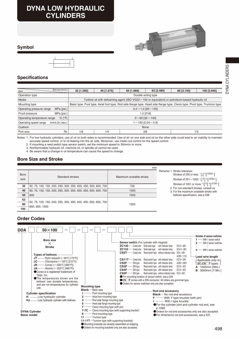
Mounting typeBlank Basic type1 Foot mounting type2 Axial foot mounting type3 Rod side flange mounting type5 Head side flange mounting type7 Clevis mounting type (with pin)7-7C Clevis mounting type (with supporting bracket)8 Pivot mounting type
11 Trunnion type11-11T Trunnion type (with supporting brackets)Mounting brackets are already assembled at shipping.Orders for mounting brackets only are also accepted. 498
Symbol
Specifications
Operation type
Media
Mounting type
Operating pressure range MPa [psi.]
Proof pressure MPa [psi.]
Operating temperature range °C [°F]
Operating speed range mm/s [in./sec.]
Cushion
Port size Rc
Double acting type
Turbine oil with defoaming agent (ISO VG22~100 or equivalent) or petroleum-based hydraulic oil
Basic type, Foot type, Axial foot type, Rod side flange type, Head side flange type, Clevis type, Pivot type, Trunnion type
0.2~1.0 [29~145]
1.5 [218]
0~60 [32~140]
1~150 [0.04~5.9]
None
Bore size mm [in.]Item 32 [1.260] 40 [1.575] 50 [1.969] 63 [2.480] 80 [3.150] 100 [3.940]
1/8 1/4 3/8 1/2
Order Codes
Bore size×
Stroke
50×100 --- -
Maximum avaiable stroke
mm
Bore
sizeStandard strokes
50, 75, 100, 150, 200, 250, 300, 350, 400, 450, 500, 600, 700
50, 75, 100, 150, 200, 250, 300, 350, 400, 450, 500, 600, 700
800, 900, 1000
32
40
50
63
80
100
Bore Size and Stroke
50, 75, 100, 150, 200, 250, 300, 350, 400, 450, 500, 600, 700
800
700
1000
1500
1500
DDA
Cylinder specificationH Low hydraulic cylinderHJ Low hydraulic cylinder with bellows
Types of bellowsJT Nylon tarpaulin (~80°C [176°F])JC Chloroprene (~100°C [212°F])JK Conex (~200°C [392°F])JA Alumix (~250°C [482°F])Conex is a registered trademark of
Teijin, Inc.The temperatures shown are the
bellows’ own durable temperatures,and are not temperatures for cylinderuse.
DYNA CylinderBasic model
DYNA LOW HYDRAULICCYLINDERS
Remarks: 1. Stroke tolerance; Strokes of 250 or less:
Strokes of 251~1000:
Strokes of 1001 or more:2. For non-standard strokes, consult us.3. For the maximum available stroke with
bellows specification, see p.538.
+10
+0.039in.+0.039in.[ ]
+1.5+0
+0.059in.+0.059in.[ ]
+2.0+0
+0.079in.+0.079in.[ ]
Rod end accessoryBlank No rod end accessoryY With Y type knuckle (with pin)I With I type knuckleFor the cylinder joint and cylinder rod end, see
p.1568.Orders for rod end accessories only are also accepted.For dimensions rod end accessories, see p.537.
Sensor switch (For cylinder with magnet)ZC130 2-lead wire Solid state type with indicator lamp DC10~28VZC153 3-lead wire Solid state type with indicator lamp DC4.5~28VCS5T 2-lead wire Reed switch type without indicator lamp DC5~28V
AC85~115VCS11T 2-lead wire Reed switch type with indicator lamp DC10~28VCS2F DIN type Reed switch type with indicator lamp AC85~230VCS3F DIN type Reed switch type with indicator lamp DC10~30VCS4F DIN type Reed switch type with indicator lamp DC10~30VCS5F DIN type Reed switch type without indicator lamp DC3~30VFor mounting location of sensor switch, see p.534CSF comes with a DIN connector. All others are grommet type.Orders for sensor switches only are also accepted.
( )Lead wire length
Applicable only toZC,CST types
A : 1000mm [39in.]B : 3000mm [118in.]
Number of sensor switches1 With 1 sensor switch2 With 2 sensor switches
n With n sensor switches… …
DYNA
CYL
INDE
RS
Notes: 1. For low hydraulic cylinders, use of oil on both sides is recommended. Use of air on one side and oil on the other side could lead to an inability to maintainaccurate speed control, or to oil leaking into the air side. Moreover, use meter-out control for the speed control.
2. If mounting a reed switch type sensor switch, set the minimum speed to 30mm/s or more.3. Nonflammable hydraulic oil, machine oil, or spindle oil cannot be used.4. Be aware that a change in oil temperature can cause the speed to change.
498_513ダイナシリンダ_ENG 07.8.25 11:20 AM ページ498

499
Parts Rod seal
1
Piston seal
1
Tube gasket
2
Plug gasket
2
NHU-12
NHU-16
NHU-20
NHU-20
NHU-25
NHU-30
OSD-32A
OSD-40A
OSD-50A
OSD-63A
OSD-80A
OSD-100A
1.5×32
1.5×40
1.5×50
1.5×63
1.5×80
1.5×100
S5
S5
S6
S6
S6
S6
QuantityBore size mm32
40
50
63
80
100
Parts
Cylinder tube
Piston rod
Tie rod
Rod cover
Head cover
Rod bushing
Piston
Wear ring
Magnet
q
w
e
r
t
y
u
i
o
No.
q
w
e
r
t
y
u
i
o
Materials
Aluminum alloy
Carbon steel for machine structural use
Carbon steel for machine structural use
Aluminum die-casting
Aluminum die-casting
Oil impregnated sintered copper alloy
Aluminum alloy
Plastic
Rubber magnet
Major Parts and Materials
Inner Construction and Major Parts
Seals
Mass
!6i t!2!5u owe q!6ry!4 !1!3
!7!0!8
Parts
Plug
Tie rod nut R
Tie rod nut H
Rod end nut
Rod seal
Piston seal
Tube gasket
Snap ring
Plug gasket
!0
!1
!2
!3
!4
!5
!6
!7
No.
!0
!1
!2
!3
!4
!5
!6
!7
!8
Materials
Carbon steel for machine structural use
Rolled steel for general structural use
Chrome-molybdenum steel
Rolled steel for general structural use
Synthetic rubber (NBR)
Synthetic rubber (NBR)
Synthetic rubber (NBR)
Spring steel
Synthetic rubber (NBR)
kg [lb.]
Bore sizemm [in.]
Zero stroke mass
Basic type
0.04 [0.09]
0.04 [0.09]
0.05 [0.11]
0.22 [0.49]
0.27 [0.60]
0.34 [0.75]
0.34 [0.75]
0.87 [1.92]
1.47 [3.24]
0.57 [1.26]
0.65 [1.43]
1.02 [2.25]
1.36 [3.00]
2.32 [5.12]
2.94 [6.48]
0.68 [1.50]
0.78 [1.72]
1.19 [2.62]
1.59 [3.51]
2.70 [5.95]
3.41 [7.52]
0.71 [1.57]
0.85 [1.87]
1.34 [2.95]
1.88 [4.15]
3.17 [6.99]
4.22 [9.31]
0.77 [1.70]
1.02 [2.25]
1.41 [3.11]
1.89 [4.17]
3.92 [8.64]
5.16 [11.38]
0.76 [1.68]
0.92 [2.03]
1.41 [3.11]
1.84 [4.06]
3.24 [7.14]
4.18 [9.22]
1.22 [2.69]
1.62 [3.57]
2.11 [4.65]
3.54 [7.81]
3.96 [8.73]
4.90 [10.80]
0.69 [1.52]
0.83 [1.83]
1.28 [2.82]
1.78 [3.92]
3.40 [7.50]
4.33 [9.55]
0.87 [1.92]
1.13 [2.49]
1.57 [3.46]
2.06 [4.54]
3.48 [7.67]
4.47 [9.86]
1.09 [2.40]
1.63 [3.59]
2.07 [4.56]
2.56 [5.64]
4.20 [9.26]
5.19 [11.44]
0.00218 [0.00481]
0.00300 [0.00661]
0.00428 [0.00944]
0.00515 [0.01136]
0.00834 [0.01839]
0.01061 [0.02340]
0.16 [0.35]
0.16 [0.35]
0.21 [0.46]
0.21 [0.46]
0.62 [1.37]
1.24 [2.73]
0.06 [0.13]
Foot mounting type Axial foot mounting type Flange mounting type Clevis mtg. type
(with pin)Clevis mtg. type
(w. supporting bkt.) Pivot mounting type Trunnion type Trunnion type(w. supporting bkt.)
Additional mass for each 1mm
[0.0394in.] stroke
Mass of 1 sensor switch [with holder] Mass of knuckleZCCST Note CSF Y type knuckle
(with pin) I type knuckle
32 [1.260]
40 [1.575]
50 [1.969]
63 [2.480]
80 [3.150]
100 [3.940]
Note: For lead wire length A (1000mm [39in.]). Calculation example: For foot mounting type with bore size of 50mm, and stroke of 100mm, 1.19+(0.00428×100)=1.618kg [3.568lb.]
Remark: Items marked with a star () are available as repair kits.Order codes: For low hydraulic cylinders…SRK-NDDAH Bore size
498_513ダイナシリンダ_ENG 07.8.25 11:20 AM ページ499

500
142 +Stroke93 +Stroke
31 3115
2
2
M10×1.25
2‐Rc1/ 8Connection port
4×2‐M6×1Depth14
2‐Plugs
φ26
33
4447
6
φ12
φ26
16
25.5
16
25.5
37
10 (w
idth
acr
oss
flats
)
1732
19 3
Dimensions of Basic Type (mm)
DDAH ×32 Stroke
DDAH ×Bore size Stroke
A+Stroke
C+StrokeB
G GFE
2
R
φV
φD
T
S
N N
P P
MQ
K
2‐OConnection port
4×2‐L
H 3
J
φD
W (w
idth
acr
oss
flats
)
I
MQ
2‐Plugs
40 [1.575]
50 [1.969]
63 [2.480]
80 [3.150]
100 [3.940]
A
144
152
155
185
185
M
4
7
8
11
12
N
18
18
18
20
20
O
Rc1/4
Rc3/8
Rc3/8
Rc1/2
Rc1/2
P
25.5
24
25
29
29
Q
10
12
12
16
18
R
2
2
2
2
2
S
50
62
75
94
112
T
37
47
56
70
84
V
16
20
20
25
30
W
14
17
17
21
26
Y
2.5
3
3
3
3
B
49
57
57
75
75
C
93
93
96
108
108
D
32
38
38
44
50
E
34
42
42
54
54
F
15
15
15
21
21
G
31
31
32
36
36
H
21
29
29
37
37
I
22
27
27
32
36
J
8
11
11
13
14
K
M14×1.5
M18×1.5
M18×1.5
M22×1.5
M26×1.5
L
M 6×1 Depth 14
M 6×1 Depth 14
M 8×1.25 Depth 14
M10×1.5 Depth 15
M10×1.5 Depth 15
Code
Code
40 [1.575]
50 [1.969]
63 [2.480]
80 [3.150]
100 [3.940]
Bore mm [in.]
Bore mm [in.]
DYNA
CYL
INDE
RS
498_513ダイナシリンダ_ENG 07.8.25 11:20 AM ページ500

501
AD AG
J
H
E
B C+Stroke
A+Stroke
F G
N2
G
R
AG AD
AC+Stroke
AA+Stroke
AF
AE
Z
AH
AS
AT
T
S
I
2-OConnection port N
AB
K
W(width
across flats)
φV
Viewed from Z
AP1
AP
2
3
Dimensions of Foot Mounting Type (mm)
DDAH -1Bore size × Stroke
DDAH -2Bore size × Stroke
FD FG FG FD
FC+Stroke
FA+Stroke
FF
FQ
FE
FH
FS
FT
4‐φFP
J
H
E
B C+Stroke
2-OConnection port
A+Stroke
F
2 N
G G
R
φV
K
N
FB
W(width
across flats)
FR
I
T
S
3
Dimensions of Axial Foot Mounting Type (mm)
A
142
144
152
155
185
185
B
47
49
57
57
75
75
C
93
93
93
96
108
108
E
32
34
42
42
54
54
F
15
15
15
15
21
21
G
31
31
31
32
36
36
H
19
21
29
29
37
37
I
17
22
27
27
32
36
J
6
8
11
11
13
14
K
M10×1.25
M14×1.5
M18×1.5
M18×1.5
M22×1.5
M26×1.5
N
16
18
18
18
20
20
O
Rc1/8
Rc1/4
Rc3/8
Rc3/8
Rc1/2
Rc1/2
R
2
2
2
2
2
2
S
44
50
62
75
94
112
T
33
37
47
56
70
84
V
12
16
20
20
25
30
W
10
14
17
17
21
26
Code
32 [1.260]
40 [1.575]
50 [1.969]
63 [2.480]
80 [3.150]
100 [3.940]
AA
153
165
173
184
200
200
AB
26.5
25.5
29
26
45
45
AC
134
140
149
158
168
168
AD
9.5
12.5
12
13
16
16
AE
50
57
68
80
97
112
AF
33
36
47
56
70
84
AG
20.5
23.5
28
31
30
30
AH
28
30
36.5
41
49
57
AP1
9
11
11
11
14
14
AP2
11
13
13
13
16
16
AS
50
55
67.5
78.5
96
113
Code
FA
119
119
123
130
150
158
FB
57
59
67
67
88
88
FC
73
73
73
76
82
82
FD
23
23
25
27
34
38
FE
81
92
105
117
147
168
FF
63
70
83
95
121
140
FG
14
14
14
14
18
18
FH
22
25
31
38
47
57
FP
9
12
12
12
14
14
FQ
54
58
68
84
104
120
FR
14
16
17
22
28
30
FS
44
50
62
75.5
94
113
FT
8
8
9
9
13
14
Code
32 [1.260]
40 [1.575]
50 [1.969]
63 [2.480]
80 [3.150]
100 [3.940]
AT
3.2
3.2
3.2
3.2
4
4
32 [1.260]
40 [1.575]
50 [1.969]
63 [2.480]
80 [3.150]
100 [3.940]
32 [1.260]
40 [1.575]
50 [1.969]
63 [2.480]
80 [3.150]
100 [3.940]
Foot mounting bracket onlyDDA -1Bore size
Axial foot mounting bracket onlyDDA -2Bore size
Bore mm [in.]
Bore mm [in.]
Bore mm [in.]
Bore mm [in.]
498_513ダイナシリンダ_ENG 07.8.25 11:20 AM ページ501

502
BF
S
T
I
BE
BD
BC
4‐φBP
J
H
E
B C+Stroke
2-OConnection port
BG+Stroke
F
2 N
G G
BB
N
W(width
across flats)
K
3
φV
φD
BF
T
I
BE
5
BD
BC
4‐φBP
φV
φD
J
H
B C+Stroke
2-OConnection port
A+Stroke
G G
R
BBBA
N
N
W(width
across flats)
K
3
Dimensions of Rod Side Flange Mounting Type (mm)
DDAH -3Bore size × Stroke
DDAH -5Bore size × Stroke
Dimensions of Head Side Flange Mounting Type (mm)
A
142
144
152
155
185
185
B
47
49
57
57
75
75
C
93
93
93
96
108
108
G
31
31
31
32
36
36
H
19
21
29
29
37
37
I
17
22
27
27
32
36
J
6
8
11
11
13
14
K
M10×1.25
M14×1.5
M18×1.5
M18×1.5
M22×1.5
M26×1.5
N
16
18
18
18
20
20
O
Rc1/8
Rc1/4
Rc3/8
Rc3/8
Rc1/2
Rc1/2
R
2
2
2
2
2
2
T
33
37
47
56
70
84
V
12
16
20
20
25
30
W
10
14
17
17
21
26
Code
BA
37
39
47
47
59
59
BB
10
10
10
10
16
16
BC
47
52
65
76
95
115
BD
33
36
47
56
70
84
BE
72
84
104
116
143
162
BF
58
70
86
98
119
138
BP
7
7
9
9
12
12
Code
D
26
32
38
38
44
50
32 [1.260]
40 [1.575]
50 [1.969]
63 [2.480]
80 [3.150]
100 [3.940]
32 [1.260]
40 [1.575]
50 [1.969]
63 [2.480]
80 [3.150]
100 [3.940]
B
47
49
57
57
75
75
C
93
93
93
96
108
108
F
15
15
15
15
21
21
G
31
31
31
32
36
36
H
19
21
29
29
37
37
I
17
22
27
27
32
36
J
6
8
11
11
13
14
K
M10×1.25
M14×1.5
M18×1.5
M18×1.5
M22×1.5
M26×1.5
N
16
18
18
18
20
20
O
Rc1/8
Rc1/4
Rc3/8
Rc3/8
Rc1/2
Rc1/2
S
44
50
62
75
94
112
T
33
37
47
56
70
84
V
12
16
20
20
25
30
W
10
14
17
17
21
26
Code
BB
10
10
10
10
16
16
BC
147
152
165
176
195
115
BD
33
36
47
56
70
84
BE
72
84
104
116
143
162
BF
58
70
86
98
119
138
BG
150
152
160
163
199
199
BP
7
7
9
9
12
12
Code
D
26
32
38
38
44
50
E
32
34
42
42
54
54
32 [1.260]
40 [1.575]
50 [1.969]
63 [2.480]
80 [3.150]
100 [3.940]
32 [1.260]
40 [1.575]
50 [1.969]
63 [2.480]
80 [3.150]
100 [3.940]
Flange mounting bracket onlyDDA -3Bore size
Flange mounting bracket onlyDDA -3Bore size
Bore mm [in.]
Bore mm [in.]
Bore mm [in.]
Bore mm [in.]
DYNA
CYL
INDE
RS
498_513ダイナシリンダ_ENG 07.8.25 11:21 AM ページ502

503
φCE H9/f8
CD
CF
PA1
T
S
CT CTCP
J
H
E
B C+Stroke
2-OConnection port
CB+Stroke
CA+Stroke
F
2 N
G G
CC
CJ
N+0.7+0.5
W(width across flats)
I(width across flats)
φV
φD
K
3
DDAH -7Bore size × Stroke
DDAHWith Supporting Bracket -7-7CBore size × Stroke
Dimensions of Clevis Mounting Type (mm)
GGGH GH
GDGC
GB
GA+Stroke
GF
GE
GJ
GI
GT
4‐φGP
32 [1.260]
40 [1.575]
50 [1.969]
63 [2.480]
80 [3.150]
100 [3.940]
GA
215.5
227.5
235.5
238.5
301.5
301.5
Code GB
56.5
66.5
66.5
66.5
86.5
86.5
GC
12.5
12.5
12.5
12.5
20.5
20.5
GD
63
73
73
73
98
98
GE
85
105
105
105
135
135
GF
65
80
80
80
105
105
GG
40
40
40
40
65
65
GH
11.5
16.5
16.5
16.5
16.5
16.5
GI
57
70
76
82.5
107
116
GJ
35
45
45
45
60
60
GP
9(Thru hole)
11(Thru hole)
11(Thru hole)
11(Thru hole)
14(Thru hole)
14(Thru hole)
B
47
49
57
57
75
75
C
93
93
93
96
108
108
F
15
15
15
15
21
21
G
31
31
31
32
36
36
H
19
21
29
29
37
37
I
17
22
27
27
32
36
J
6
8
11
11
13
14
K
M10×1.25
M14×1.5
M18×1.5
M18×1.5
M22×1.5
M26×1.5
N
16
18
18
18
20
20
O
Rc1/8
Rc1/4
Rc3/8
Rc3/8
Rc1/2
Rc1/2
S
44
50
62
75
94
112
T
33
37
47
56
70
84
V
12
16
20
20
25
30
W
10
14
17
17
21
26
Code
CA
172
174
184
187
236
236
CB
159
161
169
172
215
215
CE
12
14
14
14
20
20
CJ
13
13
15
15
21
21
CP
16
20
20
20
32
32
PA1
46
58
66
66
78
78
Code
D
26
32
38
38
44
50
E
32
34
42
42
54
54
32 [1.260]
40 [1.575]
50 [1.969]
63 [2.480]
80 [3.150]
100 [3.940]
32 [1.260]
40 [1.575]
50 [1.969]
63 [2.480]
80 [3.150]
100 [3.940]
CC
19
19
19
19
32
32
CD
R15
R15
R17
R17
R24
R24
CF
R17
R17
R17
R17
R30
R30
CT
8.5
12.5
16.5
16.5
17.5
17.5
GT
8
8
8
8
12
12
Clevis mounting bracket onlyDDA -7Bore size
Bore mm [in.]
Bore mm [in.]
Bore mm [in.]
498_513ダイナシリンダ_ENG 07.8.25 11:21 AM ページ503

504
DQ
T
S
φDEH9
DD
DFJ
W(width across flats)
I(width across flats)
H
E
B C+Stroke
2-OConnection port
DB+Stroke
DA+Stroke
F
2 N
G G
DC
DJ
φV
φD
K
N3
DDAH -8Bore size × Stroke
Dimensions of Pivot Mounting Type (mm)
B
47
49
57
57
75
75
C
93
93
93
96
108
108
F
15
15
15
15
21
21
G
31
31
31
32
36
36
H
19
21
29
29
37
37
I
17
22
27
27
32
36
J
6
8
11
11
13
14
K
M10×1.25
M14×1.5
M18×1.5
M18×1.5
M22×1.5
M26×1.5
N
16
18
18
18
20
20
O
Rc1/8
Rc1/4
Rc3/8
Rc3/8
Rc1/2
Rc1/2
V
12
16
20
20
25
30
W
10
14
17
17
21
26
Code
DA
172
175
183
186
236
235
DB
159
161
169
172
215
215
DE
12
14
14
14
20
20
DJ
13
14
14
14
21
20
Code
D
26
32
38
38
44
50
E
32
34
42
42
54
54
32 [1.260]
40 [1.575]
50 [1.969]
63 [2.480]
80 [3.150]
100 [3.940]
32 [1.260]
40 [1.575]
50 [1.969]
63 [2.480]
80 [3.150]
100 [3.940]
DC
19
19
19
19
32
32
DD
R16
R17
R17
R17
R24
R24
DF
R16
R17
R17
R17
R25
R26
S
44
50
62
75
94
112
T
33
37
47
56
70
84
DQ
16
20
20
20
32
32
–0–0.070–0–0.084–0–0.084–0–0.084–0–0.100–0–0.100
Pivot mounting bracket onlyDDA -8Bore size
Bore mm [in.]
Bore mm [in.]
DYNA
CYL
INDE
RS
498_513ダイナシリンダ_ENG 07.8.25 11:21 AM ページ504

505
HF
HE
HRHQ
HB
HD
HA
HI
HJ
HT
4‐φHP
φEPe9
/H9
EE
S
T
EG EG
EB
ET
φE
Pe9
ED
EC
J
H
E
B C+StrokeStroke
22-O
Connection port
A+Stroke
F
2 N
G
EA+
G
R
N
W(width across flats)
φV
φD
K
φD
I
ER
3
Dimensions of Trunnion Type (mm)
DDAH -11Bore size × Stroke
DDAHWith Supporting Brackets -11-11TBore size × Stroke
32 [1.260]
40 [1.575]
50 [1.969]
63 [2.480]
80 [3.150]
100 [3.940]
HA
81
111
111
111
121
121
HB
60
80
80
80
85
85
HD
R16
R22
R22
R22
R22
R22
HE
85
109
122
134
160
178
HF
70
86
99
111
137
155
HI
66.5
80
86
93.5
122.5
134.5
HJ
40
50
50
50
70
70
HP
9(Thru hole)
12(Thru hole)
12(Thru hole)
12(Thru hole)
14(Thru hole)
14(Thru hole)
HQ
15
23
23
23
23
23
HR
1
2
2
2
2
2
Code
A
142
144
152
155
185
185
B
47
49
57
57
75
75
C
93
93
93
96
108
108
E
32
34
42
42
54
54
F
15
15
15
15
21
21
G
31
31
31
32
36
36
H
19
21
29
29
37
37
I
17
22
27
27
32
36
J
6
8
11
11
13
14
K
M10×1.25
M14×1.5
M18×1.5
M18×1.5
M22×1.5
M26×1.5
N
16
18
18
18
20
20
O
Rc1/8
Rc1/4
Rc3/8
Rc3/8
Rc1/2
Rc1/2
R
2
2
2
2
2
2
S
44
50
62
75
94
112
T
33
37
47
56
70
84
V
12
16
20
20
25
30
W
10
14
17
17
21
26
Code
32 [1.260]
40 [1.575]
50 [1.969]
63 [2.480]
80 [3.150]
100 [3.940]
EA
93.5
95.5
103.5
105
129
129
EB
87
113
126
138
164
182
EC
53
60
72
87
105
129
ED
20
30
30
40
40
44
EE
55
63
76
88
114
132
EG
16
25
25
25
25
25
EP
16
25
25
25
25
25
ER
R1
R1.6
R1.6
R1.6
R1.6
R2
ET
30
30
30
30
35
40
Code
32 [1.260]
40 [1.575]
50 [1.969]
63 [2.480]
80 [3.150]
100 [3.940]
D
26
32
38
38
44
50
HT
12
14
14
14
14
14
EP
16
25
25
25
25
25
Trunnion bracket onlyDDA -11Bore size
Trunnion supportingbracket onlyDDA -11TBore size
Bore mm [in.]
Bore mm [in.]
Bore mm [in.]
498_513ダイナシリンダ_ENG 07.8.25 11:21 AM ページ505

506
Symbol
Order Codes
Bore Size and Stroke
Bore size×
StrokeVoltageAC100VAC200VDC24VSingle unit valve order code
VP350-4E1-70-Voltage2 pcs. standard speed
controllers are included.
DDV 50×100 -- AC100V -- - -
Rod end accessoryBlank No rod end accessoryY With Y type knuckle (with pin)I With I type knuckleFor the cylinder joint and cylinder rod end, see p.1568.Orders for rod end accessories only are also accepted.For dimensions of rod end accessories, see p.537.
Mounting typeBlank Basic type1 Foot mounting type2 Axial foot mounting type3 Rod side flange mounting type5 Head side flange mounting type7 Clevis mounting type (with pin)7-7C Clevis mounting type (with supporting bracket)8 Pivot mounting type
11 Trunnion type11-11T Trunnion type (with supporting brackets)Mounting brackets are already assembled at
shipping.Orders for mounting brackets only are also accepted.
Remarks: 1. The order code of the valpack valve only is VP350-4E1-70-Voltage. 2. For made to order valves, or for double solenoid, 3-position, locking type manual override, plug connector, DIN connector, or
LED indicator, consult us.
mm
Bore
sizeStandard strokes
Maximum available stroke
1000
1500
50Note, 75, 100, 150, 200, 250, 300, 350, 400, 450, 500, 600, 700, 800
50Note, 75, 100, 150, 200, 250, 300, 350, 400
450, 500, 600, 700, 800, 900, 1000
40
50
63
80
100
Remarks: 1. Stroke tolerance; Strokes of 250 or less: , strokes of 251~1000: , and strokes of 1001 or more: .
2. For non-standard strokes, consult us.3. Cylinders with magnets are not available for steel tube specification.4. For the maximum available stroke with bellows specification,
see p.538.Note: Not available for trunnion type.
Lead wire lengthA 1000mm [39in.]B 3000mm [118in.]
BellowsBlank No bellowsJ With bellows
Types of bellowsJT Nylon tarpaulin (~80°C [176°F])JC Chloroprene (~100°C [212°F])JK Conex (~200°C [392°F])JA Alumix (~250°C [482°F])Conex is a registered trademark of
Teijin, Inc.The temperatures shown are the
bellows’ own durable temperatures, andare not temperatures for cylinder use.
DYNAValpack cylinder
Operation type
Media
Mounting type
Operating pressure range MPa [psi.]
Proof pressure MPa [psi.]
Operating temperature range °C [°F]
Operating speed range mm/s [in./sec.]
Speed controller
Cushion stroke mm [in.]
Lubrication
Port size Rc
Double acting type
Air
0.17~0.7 [25~102]
1.05 [152]
5~50 [41~122]
50~500 [2.0~19.7]
Exhaust throttle valve (2-way) is standard equipment
20 [0.787]16 [0.630]
Not required (If lubrication is required, use Turbine Oil Class 1 (ISO VG32) or equivalent.)
3/8
25 [0.984]
50~300[2.0~11.8]
Basic type, Foot type, Axial foot type, Rod side flange type,Head side flange type, Clevis type, Pivot type, Trunnion type
Specifications
40 [1.575] 50 [1.969] 63 [2.480] 80 [3.150] 100 [3.940]Bore size mm [in.]Item
Series
Solenoid specification
Item Model
Operation type
Number of positions and ports
Effective area [Cv] mm2
Port size Rc
Lubrication
Operating pressure range MPa [psi.]
Proof pressure MPa [psi.]
Operating temperature range °C [°F]
Shock resistance G
Mounting direction
Maximum operating frequency cycle/s
350 series
Single solenoid
VP350-4E1-70
Indirect operation
2 positions, 5 ports
26.5 [1.47]
1/4
Not required
0.17~0.7 [25~102]
1.1 [160]
5~50 [41~122]
90
Any
5
Solenoid Valve Specifications
Type
Rated voltageItem
Shading type
AC100V AC200V DC24V
90~132(100 %)+32
–10
180~264(200 %)+32
–10
21.6~26.4(24±10%)
50
34
22
4
B type
Min. 100
Grommet type: 300mm [11.8in.]
Yellow
Built-in varistor (made to order)Flywheel diode
(standard equipment)
White Red(+),Black(-)
2 4
60
32
20
50
17
11
60
16
10
-
-
65(1.6W)
Flywheel diodeincorporated for
surge suppression
Operating voltage range V
CurrentWhen rated
voltageapplied( )
Maximum allowable leakage current mA
Insulation type
Insulation resistance MΩWiring and lead wire length
Color of lead wire
Surge suppression
Frequency Hz
Starting mA(r.m.s.)
Energizing mA(r.m.s.)
Solenoid Specifications
DYNA VALPACK CYLINDERS
+10
+0.039in.+0.039in.[ ]
+1.5+0
+0.059in.+0.059in.[ ] +2.0
+0+0.079in.+0.079in.[ ]
( )
Tube materialBlank StandardFT Steel tube specification
Not available for cylinder with magnet.
Sensor switch (For cylinder with magnet)ZC130 2-lead wire Solid state type with indicator lamp DC10~28VZC153 3-lead wire Solid state type with indicator lamp DC4.5~28VCS5T 2-lead wire Reed switch type without indicator lamp DC5~28V
AC85~115VCS11T 2-lead wire Reed switch type with indicator lamp DC10~28VCS2F DIN type Reed switch type with indicator lamp AC85~230VCS3F DIN type Reed switch type with indicator lamp DC10~30VCS4F DIN type Reed switch type with indicator lamp DC10~30VCS5F DIN type Reed switch type without indicator lamp DC3~30VFor mounting location of sensor switch, see p.534.CSF comes with a DIN connector. All others are grommet type.Orders for sensor switches only are also accepted.
Number of sensor switches1 With 1 sensor switch2 With 2 sensor switches
n With n sensor switches… …
DYNA
CYL
INDE
RS
498_513ダイナシリンダ_ENG 07.8.25 11:21 AM ページ506
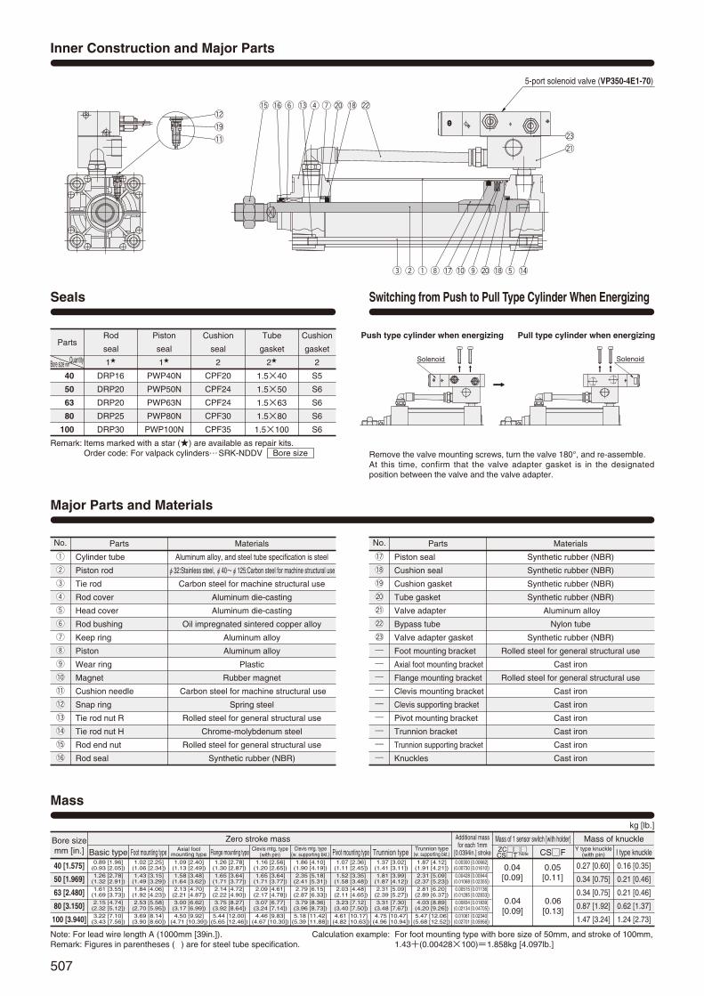
507
Inner Construction and Major Parts
Mass
!2
!9@3
@1!1
!5 !6 y !3 r u @0 !8 @2
e w q i !7 !0 o @0 !8 t !4
5-port solenoid valve (VP350-4E1-70)
kg [lb.]
Bore sizemm [in.]
Zero stroke mass
Basic type0.89 [1.96]
(0.93 [2.05])1.26 [2.78]
(1.32 [2.91])1.61 [3.55]
(1.69 [3.73])2.15 [4.74]
(2.32 [5.12])3.22 [7.10]
(3.43 [7.56])
1.02 [2.25](1.06 [2.34])1.43 [3.15]
(1.49 [3.29])1.84 [4.06]
(1.92 [4.23])2.53 [5.58]
(2.70 [5.95])3.69 [8.14]
(3.90 [8.60])
1.09 [2.40](1.13 [2.49])1.58 [3.48]
(1.64 [3.62])2.13 [4.70]
(2.21 [4.87])3.00 [6.62]
(3.17 [6.99])4.50 [9.92]
(4.71 [10.39])
1.26 [2.78](1.30 [2.87])1.65 [3.64]
(1.71 [3.77])2.14 [4.72]
(2.22 [4.90])3.75 [8.27]
(3.92 [8.64])5.44 [12.00]
(5.65 [12.46])
1.16 [2.56](1.20 [2.65])1.65 [3.64]
(1.71 [3.77])2.09 [4.61]
(2.17 [4.78])3.07 [6.77]
(3.24 [7.14])4.46 [9.83]
(4.67 [10.30])
1.86 [4.10](1.90 [4.19])2.35 [5.18]
(2.41 [5.31])2.79 [6.15]
(2.87 [6.33])3.79 [8.36]
(3.96 [8.73])5.18 [11.42]
(5.39 [11.88])
1.07 [2.36](1.11 [2.45])1.52 [3.35]
(1.58 [3.48])2.03 [4.48]
(2.11 [4.65])3.23 [7.12]
(3.40 [7.50])4.61 [10.17]
(4.82 [10.63])
1.37 [3.02](1.41 [3.11])1.81 [3.99]
(1.87 [4.12])2.31 [5.09]
(2.39 [5.27])3.31 [7.30]
(3.48 [7.67])4.75 [10.47]
(4.96 [10.94])
1.87 [4.12](1.91 [4.21])2.31 [5.09]
(2.37 [5.23])2.81 [6.20]
(2.89 [6.37])4.03 [8.89]
(4.20 [9.26])5.47 [12.06]
(5.68 [12.52])
0.00300 [0.00662](0.00730 [0.01610])0.00428 [0.00944]
(0.01068 [0.02355])0.00515 [0.01136]
(0.01285 [0.02833])0.00834 [0.01839]
(0.02134 [0.04705])0.01061 [0.02340]
(0.02701 [0.05956])
0.04 [0.09]
0.04 [0.09]
0.05 [0.11]
0.27 [0.60]
0.34 [0.75]
0.34 [0.75]
0.87 [1.92]
1.47 [3.24]
0.16 [0.35]
0.21 [0.46]
0.21 [0.46]
0.62 [1.37]
1.24 [2.73]
0.06 [0.13]
Foot mounting type Axial foot mounting type Flange mounting type Clevis mtg. type
(with pin)Clevis mtg. type
(w. supporting bkt.) Pivot mounting type Trunnion type Trunnion type(w. supporting bkt.)
Additional mass for each 1mm
[0.0394in.] stroke
Mass of 1 sensor switch [with holder] Mass of knuckleZCCST Note CSF Y type knuckle
(with pin) I type knuckle
40 [1.575]
50 [1.969]
63 [2.480]
80 [3.150]
100 [3.940]
Note: For lead wire length A (1000mm [39in.]).Remark: Figures in parentheses ( ) are for steel tube specification.
Calculation example: For foot mounting type with bore size of 50mm, and stroke of 100mm,1.43+(0.00428×100)=1.858kg [4.097lb.]
Parts
Cylinder tube
Piston rod
Tie rod
Rod cover
Head cover
Rod bushing
Keep ring
Piston
Wear ring
Magnet
Cushion needle
Snap ring
Tie rod nut R
Tie rod nut H
Rod end nut
Rod seal
Materials
Aluminum alloy, and steel tube specification is steel
φ32:Stainless steel, φ40~φ125:Carbon steel for machine structural use
Carbon steel for machine structural use
Aluminum die-casting
Aluminum die-casting
Oil impregnated sintered copper alloy
Aluminum alloy
Aluminum alloy
Plastic
Rubber magnet
Carbon steel for machine structural use
Spring steel
Rolled steel for general structural use
Chrome-molybdenum steel
Rolled steel for general structural use
Synthetic rubber (NBR)
Major Parts and Materials
Parts
Piston seal
Cushion seal
Cushion gasket
Tube gasket
Valve adapter
Bypass tube
Valve adapter gasket
Foot mounting bracket
Axial foot mounting bracket
Flange mounting bracket
Clevis mounting bracket
Clevis supporting bracket
Pivot mounting bracket
Trunnion bracket
Trunnion supporting bracket
Knuckles
Materials
Synthetic rubber (NBR)
Synthetic rubber (NBR)
Synthetic rubber (NBR)
Synthetic rubber (NBR)
Aluminum alloy
Nylon tube
Synthetic rubber (NBR)
Rolled steel for general structural use
Cast iron
Rolled steel for general structural use
Cast iron
Cast iron
Cast iron
Cast iron
Cast iron
Cast iron
No. No.
q
w
e
r
t
y
u
i
o
!0
!1
!2
!3
!4
!5
!6
q
w
e
r
t
y
u
i
o
!0
!1
!2
!3
!4
!5
!6
!7
!8
!9
@0
@1
@2
@3
!7
!8
!9
@0
@1
@2
@3
―
―
―
―
―
―
―
―
―
PartsRod
seal
1
Piston
seal
1
Cushion
seal
2
Tube
gasket
2
Cushion
gasket
2
DRP16
DRP20
DRP20
DRP25
DRP30
PWP40N
PWP50N
PWP63N
PWP80N
PWP100N
CPF20
CPF24
CPF24
CPF30
CPF35
1.5×40
1.5×50
1.5×63
1.5×80
1.5×100
QuantityBore size mm
40
50
63
80
100
Seals
Remark: Items marked with a star () are available as repair kits.Order code: For valpack cylinders…SRK-NDDV Bore size
S5
S6
S6
S6
S6
Solenoid Solenoid
Switching from Push to Pull Type Cylinder When Energizing
Remove the valve mounting screws, turn the valve 180°, and re-assemble.At this time, confirm that the valve adapter gasket is in the designatedposition between the valve and the valve adapter.
Push type cylinder when energizing Pull type cylinder when energizing
498_513ダイナシリンダ_ENG 07.8.25 11:21 AM ページ507

508
40 [1.575]
50 [1.969]
63 [2.480]
80 [3.150]
100 [3.940]
40 [1.575]
50 [1.969]
63 [2.480]
80 [3.150]
100 [3.940]
Code
Code
Dimensions of Basic Type (mm)
DDV ×Bore size Stroke
8-LBoth sides
S
T
I
SV
35
Q
35
18.5
(29 MAX.)35
A7+Stroke
110.2
101.2
40
10.5 25.5
9
(300)2-Cushion needle
Rc3/8
P
2-RC1/4(with speed controller)
2312
22
φDφV
J
H 3
E
B
F G
C+Stroke
A+Stroke
G
R
Y
P
N
W(width across flats)
K
29 M
AX
.
Q
QA
A
144
152
155
185
185
L
M6×1 Depth 14
M6×1 Depth 14
M8×1.25 Depth 14
M10×1.5 Depth 15
M10×1.5 Depth 15
N
18
18
18
20
20
P
25.5
24
25
29
29
Q
10
12
12
16
18
QA
4
7
8
11
12
R
2
2
2
2
2
S
50
62
75
94
112
SV
(86.5)
(92.5)
(99)
(108.5)
(117.5)
T
37
47
56
70
84
V
16
20
20
25
30
W
14
17
17
21
26
Y
2.5
3
3
3
3
A7
149.5
157.5
160.5
188.5
188.5
B
49
57
57
75
75
C
93
93
96
108
108
D
32
38
38
44
50
E
34
42
42
54
54
F
15
15
15
21
21
G
31
31
32
36
36
H
21
29
29
37
37
I
22
27
27
32
36
J
8
11
11
13
14
K
M14×1.5
M18×1.5
M18×1.5
M22×1.5
M26×1.5
DDV Bore size
Bore mm [in.]
Bore mm [in.]
DYNA
CYL
INDE
RS
498_513ダイナシリンダ_ENG 07.8.25 11:21 AM ページ508

509
Dimensions of Foot Mounting Type (mm)
DDV -1Bore size × Stroke
DDV -2Bore size × Stroke
Dimensions of Axial Foot Mounting Type (mm)
T
AF
I
AE
A7+Stroke
2-RC1/4(with speed controller)
232
2
J
H 3
E
B
F
G
C+Stroke
G
R
Y
P
W(width across flats)
K
AD AG
AA+Stroke
AC+Stroke
ADAG
AB
AS
AH
AT
SV
Q
35
18.5 QA
φV
110.2
101.2
40
10.5 25.5
9
Rc3/8
12
N
(29 MAX.)35
Z
Viewed from Z
AP1
AP
2
T
I
A7+Stroke
2-RC1/4(with speed controller)
232
2
J
H 3
E
B
F
R
Y
P
4-φFP
FS
FT
FR F
H
FB FC+Stroke
FA+Stroke
FQ
FF
FE
FD FG
K
(width across flats)W
FDFG
110.2
101.2
40
10.5 25.5
9
Rc3/8
12
φV
N
Q
SV
35
18.5 QA
(29 MAX.)35
40 [1.575]
50 [1.969]
63 [2.480]
80 [3.150]
100 [3.940]
40 [1.575]
50 [1.969]
63 [2.480]
80 [3.150]
100 [3.940]
Code
Code
40 [1.575]
50 [1.969]
63 [2.480]
80 [3.150]
100 [3.940]
40 [1.575]
50 [1.969]
63 [2.480]
80 [3.150]
100 [3.940]
Code
Code
A7
149.5
157.5
160.5
188.5
188.5
AA
165
173
184
200
200
AB
25.5
29
26
45
45
AC
140
149
158
168
168
AD
12.5
12
13
16
16
AE
57
68
80
97
112
AF
36
47
56
70
84
AG
23.5
28
31
30
30
AH
30
36.5
41
49
57
AP1
11
11
11
14
14
AP2
13
13
13
16
16
AS
55
67.5
78.5
96
113
AT
3.2
3.2
3.2
4
4
B
49
57
57
75
75
C
93
93
96
108
108
E
34
42
42
54
54
F
15
15
15
21
21
G
31
31
32
36
36
H
21
29
29
37
37
I
22
27
27
32
36
J
8
11
11
13
14
K
M14×1.5
M18×1.5
M18×1.5
M22×1.5
M26×1.5
N
18
18
18
20
20
P
25.5
24
25
29
29
Q
10
12
12
16
18
QA
4
7
8
11
12
R
2
2
2
2
2
SV
(86.5)
(92.5)
(99)
(108.5)
(117.5)
T
37
47
56
70
84
V
16
20
20
25
30
W
14
17
17
21
26
Y
2.5
3
3
3
3
A7
149.5
157.5
160.5
188.5
188.5
B
49
57
57
75
75
E
34
42
42
54
54
F
15
15
15
21
21
H
21
29
29
37
37
I
22
27
27
32
36
J
8
11
11
13
14
K
M14×1.5
M18×1.5
M18×1.5
M22×1.5
M26×1.5
N
18
18
18
20
20
P
25.5
24
25
29
29
Q
10
12
12
16
18
QA
4
7
8
11
12
R
2
2
2
2
2
SV
(86.5)
(92.5)
(99)
(108.5)
(117.5)
T
37
47
56
70
84
V
16
20
20
25
30
W
14
17
17
21
26
Y
2.5
3
3
3
3
FA
119
123
130
150
158
FB
59
67
67
88
88
FC
73
73
76
82
82
FD
23
25
27
34
38
FE
92
105
117
147
168
FF
70
83
95
121
140
FG
14
14
14
18
18
FH
25
31
38
47
57
FP
12
12
12
14
14
FQ
58
68
84
104
120
FR
16
17
22
28
30
FS
50
62
75.5
94
113
FT
8
9
9
13
14
Foot mounting bracket onlyDDA -1Bore size
Axial foot mountingbracket onlyDDA -2Bore size
Bore mm [in.]
Bore mm [in.]
Bore mm [in.]
Bore mm [in.]
498_513ダイナシリンダ_ENG 07.8.25 11:21 AM ページ509

510
S
T
I
A7+Stroke
2-RC1/4(with speed controller)
232
2
φD
J
H 3
E
B
F G
C+Stroke
BG+Stroke
G
BB
Y
P
W(width across flats)K
BF
BE
4-φBP
BC
BD
SV
35
18.5 QA
110.2
101.2
40
10.5 25.5
9
Rc3/8
12
φV
N
Q
(29 MAX.)35
Dimensions of Rod Side Flange Mounting Type (mm)
DDV -3Bore size × Stroke
DDV -5Bore size × Stroke
Dimensions of Head Side Flange Mounting Type (mm)
40 [1.575]
50 [1.969]
63 [2.480]
80 [3.150]
100 [3.940]
40 [1.575]
50 [1.969]
63 [2.480]
80 [3.150]
100 [3.940]
Code
Code
40 [1.575]
50 [1.969]
63 [2.480]
80 [3.150]
100 [3.940]
40 [1.575]
50 [1.969]
63 [2.480]
80 [3.150]
100 [3.940]
Code
Code
A7+Stroke
2-RC1/4(with speed controller)
232
2φ
D
J
H 3
BA
B
G
C+Stroke
A+Stroke
G
R
Y
P
W(width across flats)K
SV
35
18.5 QA
110.2
101.2
40
10.5 25.5
9
Rc3/8
12
φV
N
Q
(29 MAX.)35
4-φBP
BC
BD
5
BE
BF
T
I
BB
A
144
152
155
185
185
A7
149.5
157.5
160.5
188.5
188.5
B
49
57
57
75
75
C
93
93
96
108
108
D
32
38
38
44
50
G
31
31
32
36
36
H
21
29
29
37
37
I
22
27
27
32
36
J
8
11
11
13
14
K
M14×1.5
M18×1.5
M18×1.5
M22×1.5
M26×1.5
N
18
18
18
20
20
P
25.5
24
25
29
29
Q
10
12
12
16
18
QA
4
7
8
11
12
R
2
2
2
2
2
SV
(86.5)
(92.5)
(99)
(108.5)
(117.5)
T
37
47
56
70
84
V
16
20
20
25
30
W
14
17
17
21
26
Y
2.5
3
3
3
3
BA
39
47
47
59
59
BB
10
10
10
16
16
BC
52
65
76
95
115
BD
36
47
56
70
84
BE
84
104
116
143
162
BF
70
86
98
119
138
BP
7
9
9
12
12
BB
10
10
10
16
16
BC
52
65
76
95
115
BD
36
47
56
70
84
BE
84
104
116
143
162
BF
70
86
98
119
138
BG
152
160
163
199
199
BP
7
9
9
12
12
A7
149.5
157.5
160.5
188.5
188.5
B
49
57
57
75
75
C
93
93
96
108
108
D
32
38
38
44
50
E
34
42
42
54
54
F
15
15
15
21
21
G
31
31
32
36
36
H
21
29
29
37
37
I
22
27
27
32
36
J
8
11
11
13
14
K
M14×1.5
M18×1.5
M18×1.5
M22×1.5
M26×1.5
N
18
18
18
20
20
P
25.5
24
25
29
29
Q
10
12
12
16
18
QA
4
7
8
11
12
S
50
62
75
94
112
SV
(86.5)
(92.5)
(99)
(108.5)
(117.5)
T
37
47
56
70
84
V
16
20
20
25
30
W
14
17
17
21
26
Y
2.5
3
3
3
3
Flange mounting bracket onlyDDA -3Bore size
Flange mounting bracket onlyDDA -3Bore size
Bore mm [in.]
Bore mm [in.]
Bore mm [in.]
Bore mm [in.]
DYNA
CYL
INDE
RS
498_513ダイナシリンダ_ENG 07.8.25 11:21 AM ページ510

511
40 [1.575]
50 [1.969]
63 [2.480]
80 [3.150]
100 [3.940]
Code
40 [1.575]
50 [1.969]
63 [2.480]
80 [3.150]
100 [3.940]
Code
40 [1.575]
50 [1.969]
63 [2.480]
80 [3.150]
100 [3.940]
Code
DDV -7Bore size × Stroke
DDVWith Supporting Bracket -7-7CBore size × Stroke
Dimensions of Clevis Mounting Type (mm)
A7+Stroke
2-RC1/4(with speed controller)
232
2φ
D
J
H 3
E
B
F G
C+Stroke
G
Y
P
W(width across flats)
(width across flats)
K
CA+Stroke
CB+Stroke
φCE H9/f8
CD
CF
CJ
CC
φV
φD
PA1
S
T
CT CT
CP+0.7+0.5
SV
35
(29 MAX.)
18.5
35
110.2
101.2
40
10.5 25.5
9
Rc3/8
I
12
N
Q
QA
GGGH GH
GDGC
GB
GA+Stroke
GF
GE
GJ
GI
GT
4‐φGP
A7
149.5
157.5
160.5
188.5
188.5
B
49
57
57
75
75
C
93
93
96
108
108
D
32
38
38
44
50
E
34
42
42
54
54
F
15
15
15
21
21
G
31
31
32
36
36
H
21
29
29
37
37
I
22
27
27
32
36
J
8
11
11
13
14
K
M14×1.5
M18×1.5
M18×1.5
M22×1.5
M26×1.5
N
18
18
18
20
20
P
25.5
24
25
29
29
Q
10
12
12
16
18
QA
4
7
8
11
12
S
50
62
75
94
112
SV
(86.5)
(92.5)
(99)
(108.5)
(117.5)
T
37
47
56
70
84
V
16
20
20
25
30
W
14
17
17
21
26
Y
2.5
3
3
3
3
CA
174
184
187
236
236
CB
161
169
172
215
215
CC
19
19
19
32
32
CD
R15
R17
R17
R24
R24
CE
14
14
14
20
20
CF
R17
R17
R17
R30
R30
CJ
13
15
15
21
21
CP
20
20
20
32
32
CT
12.5
16.5
16.5
17.5
17.5
PA1
58
66
66
78
78
GA
227.5
235.5
238.5
301.5
301.5
GB
66.5
66.5
66.5
86.5
86.5
GC
12.5
12.5
12.5
20.5
20.5
GD
73
73
73
98
98
GE
105
105
105
135
135
GF
80
80
80
105
105
GG
40
40
40
65
65
GH
16.5
16.5
16.5
16.5
16.5
GI
70
76
82.5
107
116
GJ
45
45
45
60
60
GP
11(Thru hole)
11(Thru hole)
11(Thru hole)
14(Thru hole)
14(Thru hole)
GT
8
8
8
12
12
Clevis mounting bracket onlyDDA -7Bore size
Bore mm [in.]
Bore mm [in.]
Bore mm [in.]
498_513ダイナシリンダ_ENG 07.8.25 11:21 AM ページ511

512
40 [1.575]
50 [1.969]
63 [2.480]
80 [3.150]
100 [3.940]
Code
DDV -8Bore size × Stroke
Dimensions of Pivot Mounting Type (mm)
(with speed controller)
232
2
J
H 3
E
B
F G
C+Stroke
G
Y
P
W(width across flats)K
DA+Stroke
DB+Stroke
DQ
T
S
φDEH9
DD
DF
N
DC
DJ
A7+Stroke
2-RC1/4
(width across flats)
φV
φD
SV
35
(29 MAX.)
18.5
35
110.2
101.2
40
10.5 25.5
9
Rc3/8
I
12
Q
QA
40 [1.575]
50 [1.969]
63 [2.480]
80 [3.150]
100 [3.940]
Code A7
149.5
157.5
160.5
188.5
188.5
B
49
57
57
75
75
C
93
93
96
108
108
D
32
38
38
44
50
E
34
42
42
54
54
F
15
15
15
21
21
G
31
31
32
36
36
H
21
29
29
37
37
I
22
27
27
32
36
J
8
11
11
13
14
K
M14×1.5
M18×1.5
M18×1.5
M22×1.5
M26×1.5
N
18
18
18
20
20
P
25.5
24
25
29
29
Q
10
12
12
16
18
QA
4
7
8
11
12
S
50
62
75
94
112
SV
(86.5)
(92.5)
(99)
(108.5)
(117.5)
T
37
47
56
70
84
V
16
20
20
25
30
W
14
17
17
21
26
Y
2.5
3
3
3
3
DA
175
183
186
236
235
DB
161
169
172
215
215
DC
19
19
19
32
32
DD
R17
R17
R17
R24
R24
DE
14
14
14
20
20
DF
R17
R17
R17
R25
R26
DJ
14
14
14
21
20
DQ
20
20
20
32
32
–0–0.084–0–0.084–0–0.084–0–0.100–0–0.100
Pivot mounting bracket onlyDDA -8Bore size
Bore mm [in.]
Bore mm [in.]
DYNA
CYL
INDE
RS
498_513ダイナシリンダ_ENG 07.8.25 11:21 AM ページ512

513
Dimensions of Trunnion Type (mm)
DDV -11Bore size × Stroke
DDVWith Supporting Brackets -11-11TBore size × Stroke
40 [1.575]
50 [1.969]
63 [2.480]
80 [3.150]
100 [3.940]
Code
S
T
I
2-RC1/4(with speed controller)
232
2φ
D
J
H 3
E
B
F G
C+Stroke
A+Stroke
G
R
Y
P
W(width across flats)K
ET
Stroke2EA+
φE
Pe9
ED
EC
EEEG EG
EB
ER
(29 MAX.)35
SV
35
18.5
A7+Stroke
110.2
101.2
40
10.5 25.5
9
Rc3/8
12
N
Q
QA
φV
HEHF 4-φHP
HT
HJ
HI
φEPe9/H9
HQ HR
HD
HB
HA
A
144
152
155
185
185
A7
149.5
157.5
160.5
188.5
188.5
B
49
57
57
75
75
C
93
93
96
108
108
D
32
38
38
44
50
E
34
42
42
54
54
F
15
15
15
21
21
G
31
31
32
36
36
H
21
29
29
37
37
I
22
27
27
32
36
J
8
11
11
13
14
K
M14×1.5
M18×1.5
M18×1.5
M22×1.5
M26×1.5
N
18
18
18
20
20
P
25.5
24
25
29
29
Q
10
12
12
16
18
QA
4
7
8
11
12
R
2
2
2
2
2
S
50
62
75
94
112
SV
(86.5)
(92.5)
(99)
(108.5)
(117.5)
T
37
47
56
70
84
V
16
20
20
25
30
W
14
17
17
21
26
Y
2.5
3
3
3
3
40 [1.575]
50 [1.969]
63 [2.480]
80 [3.150]
100 [3.940]
EA
95.5
103.5
105
129
129
EB
113
126
138
164
182
EC
60
72
87
105
129
ED
30
30
40
40
44
EE
63
76
88
114
132
EG
25
25
25
25
25
EP
25
25
25
25
25
ER
R1.6
R1.6
R1.6
R1.6
R2
ET
30
30
30
35
40
Code
40 [1.575]
50 [1.969]
63 [2.480]
80 [3.150]
100 [3.940]
HA
111
111
111
121
121
HB
80
80
80
85
85
HD
R22
R22
R22
R22
R22
HE
109
122
134
160
178
HF
86
99
111
137
155
HI
80
86
93.5
122.5
134.5
HJ
50
50
50
70
70
HP
12(Thru hole)
12(Thru hole)
12(Thru hole)
12(Thru hole)
12(Thru hole)
HQ
23
23
23
23
23
HR
2
2
2
2
2
HT
14
14
14
14
14
EP
25
25
25
25
25
Code
Trunnion bracket onlyDDA -11Bore size
Trunnion supportingbracket onlyDDA -11TBore size
Bore mm [in.]
Bore mm [in.]
Bore mm [in.]
498_513ダイナシリンダ_ENG 07.8.25 11:21 AM ページ513

Sensor switchZC130 2-lead wire Solid state type with indicator lamp DC10~28VZC153 3-lead wire Solid state type with indicator lamp DC4.5~28VCS5T 2-lead wire Reed switch type without indicator lamp DC5~28V
AC85~115VCS11T 2-lead wire Reed switch type with indicator lamp DC10~28VCS2F DIN type Reed switch type with indicator lamp AC85~230VCS3F DIN type Reed switch type with indicator lamp DC10~30VCS4F DIN type Reed switch type with indicator lamp DC10~30VCS5F DIN type Reed switch type without indicator lamp DC3~30VFor mounting location of sensor switch, see p.534.Cylinders with magnet are not available in steel tube specification.CSF comes with a DIN connector. All others are grommet type.Orders for sensor switches only are also accepted.
514
Symbols
Specifications
Order Codes
Bore Size and Stroke
Operation type
Media
Mounting type
Operating pressure range MPa [psi.]
Proof pressure MPa [psi.]
Operating temperature range °C [°F]
Operating speed range mm/s [in./sec.]
Cushion
Cushion stroke mm [in.]
Lubrication
Maximum holding force (at end keep) N [lbf.]
Backlash (at end keep) mm [in.]
Port size Rc
Double acting type with head side or rod side stroke end keep mechanism
Air
Basic type, Foot type, Axial foot type, Rod side flange type, Head side flange type, Clevis type, Pivot type, Trunnion type
0.15~1.0 [22~145]
1.5 [218]
―10~70 [14~158] (Freezing prohibited, With sensor is 0~60 [32~140].)
30~700 [1.2~27.6]
Variable cushion at both ends of stroke
Not required (If lubrication is required, use Turbine Oil Class 1 (ISO VG32) or equivalent.)
1/4 3/8 1/2
16 [0.630]
880 [198] 3519 [791]
1.0 [0.039] MAX
5498 [1236]2182 [491]1374 [309]
20 [0.787] 25 [0.984]
40 [1.575] 50 [1.969] 63 [2.480] 80 [3.150] 100 [3.940]Bore size mm [in.]Item
Bore size×
Stroke
End keep positionHL Head side end keepRL Rod side end keep
Non-ion specificationBlank StandardNCU Non-ion specification
50×100 --- - - - -
Mounting typeBlank Basic type1 Foot mounting type2 Axial foot mounting type3 Rod side flange mounting type5 Head side flange mounting type7 Clevis mounting type (with pin)7-7C Clevis mounting type (with supporting bracket)8 Pivot mounting type
11 Trunnion type11-11T Trunnion type (with supporting brackets)Mounting brackets are already assembled at shipping.Orders for mounting brackets only are also accepted.
Head side end keep Rod side end keep
mm
Bore
sizeStandard strokes
Maximum available stroke
1000
1500
50, 75, 100, 150, 200, 250, 300, 350, 400, 450, 500, 600, 700, 800
50, 75, 100, 150, 200, 250, 300, 350, 400
450, 500, 600, 700, 800, 900, 1000
40
50
63
80
100
DDA
Rod end accessoryBlank No rod end accessoryY With Y type knuckle (with pin)I With I type knuckleFor the cylinder joint and cylinder rod end, see p.1568.Orders for rod end accessories only are also accepted.For dimensions of rod end accessories, see p.537.
Cylinder specificationK End keep cylinderJK End keep cylinder with bellows
Types of bellowsJT Nylon tarpaulin (~80°C [176°F])JC Chloroprene (~100°C [212°F])JK Conex (~200°C [392°F])JA Alumix (~250°C [482°F])Conex is a registered trademark of Teijin, Inc.The temperatures shown are the bellows’
own durable temperatures, and are nottemperatures for cylinder use.
DYNA CylinderBasic model
DYNA END KEEPCYLINDERS
Head Side End Keep, Rod Side End Keep
Remarks: 1. Stroke tolerance; Strokes of 250 or less:
Strokes of 251~1000:
Strokes of 1001 or more: 2. For non-standard strokes, consult us.3. Cylinders with magnets are not available for steel tube specification.4. For the maximum available stroke with bellows specification, see
p.538.
+10
+0.039in.+0.039in.[ ]
+1.5+0
+0.059in.+0.059in.[ ]
+2.0+0
+0.079in.+0.079in.[ ]
( )
Tube materialBlank Standard (Aluminum tube)FT Steel tube specification
Not available for cylinder with magnet.
( )Lead wire length
Applicable only toZC,CST types
A : 1000mm [39in.]B : 3000mm [118in.]
Number of sensor switches1 With 1 sensor switch2 With 2 sensor switches
n With n sensor switches… …
DYNA
CYL
INDE
RS
514_523ダイナシリンダ_ENG 07.8.25 11:22 AM ページ514

515
Parts
Cylinder tube
Piston rod
Tie rod
Rod cover
Head cover
Keep ring
Rod bushing
Piston
Wear ring
Magnet
Cushion needle
Snap ring
Tie rod nut R
Tie rod nut H
Lock cover
Spring
Lock piston
Button bolt
Lock sleeve
Rod end nut
Rod seal
Piston seal
Cushion seal
Cushion gasket
Tube gasket
Lock piston seal
Piston gasket
Bumper
q
w
e
r
t
y
u
i
o
!0
!1
!2
!3
!4
!5
!6
!7
!8
!9
@0
@1
@2
@3
@4
@5
@6
@7
@8
No.
q
w
e
r
t
y
u
i
o
!0
!1
!2
!3
!4
!5
!6
!7
!8
!9
@0
@1
@2
@3
@4
@5
@6
@7
@8
Materials
Aluminum alloy
Carbon steel for machine structural use
Carbon steel for machine structural use
Aluminum die-casting
Aluminum alloy
Aluminum alloy
Oil impregnated sintered copper alloy
Aluminum alloy
Plastic
Rubber magnet
Carbon steel for machine structural use
Spring steel
Rolled steel for general structural use
Chrome-molybdenum steel
Aluminum alloy
Spring steel
Aluminum alloy
Chrome-molybdenum steel
Carbon steel for machine structural use
Rolled steel for general structural use
Synthetic rubber (NBR)
Synthetic rubber (NBR)
Synthetic rubber (NBR)
Synthetic rubber (NBR)
Synthetic rubber (NBR)
Synthetic rubber (NBR)
Synthetic rubber (NBR)
Urethane rubber
Major Parts and Materials
Inner Construction and Major Parts
Parts
Cylinder tube
Piston rod
Tie rod
Rod cover
Head cover
Piston
Wear ring
Magnet
Cushion needle
Snap ring
Tie rod nut R
Tie rod nut H
Lock cover
Spring
Lock piston
Button bolt
Rod end nut
Rod seal
Piston seal
Cushion seal
Cushion gasket
Tube gasket
Lock piston seal
Bumper
q
w
e
r
t
y
u
i
o
!0
!1
!2
!3
!4
!5
!6
!7
!8
!9
@0
@1
@2
@3
@4
No.
q
w
e
r
t
y
u
i
o
!0
!1
!2
!3
!4
!5
!6
!7
!8
!9
@0
@1
@2
@3
@4
Materials
Aluminum alloy
Carbon steel for machine structural use
Carbon steel for machine structural use
Aluminum alloy
Aluminum die-casting
Aluminum alloy
Plastic
Rubber magnet
Carbon steel for machine structural use
Spring steel
Rolled steel for general structural use
Chrome-molybdenum steel
Aluminum alloy
Spring steel
Aluminum alloy
Chrome-molybdenum steel
Rolled steel for general structural use
Synthetic rubber (NBR)
Synthetic rubber (NBR)
Synthetic rubber (NBR)
Synthetic rubber (NBR)
Synthetic rubber (NBR)
Synthetic rubber (NBR)
Urethane rubber
Cross section of locking
@7e i@3@5 qr!3 y@1w u!2@4 @0!1 @8!8 @6 !9 !4!7!6!5o!0 t@2
Cross section of locking(when locked) @2r @0!5!3 @4!6@3 !4!8w !2!0@1 !7o !1ui tyq !9e
Head side end keep
Rod side end keep
Head side end keep Rod side end keep
514_523ダイナシリンダ_ENG 07.8.25 11:22 AM ページ515

516
φ40,φ50
φD
N9N
P9P
MQ
φD
2-Cushion needle
2-O
4×2-L
φ39
LB2.
6
φV
W(width across flats)
G G9
C9+Stroke
F
B
2
R
H 3
A9+Stroke
J
E
S
T
2.6
I
K
Dimensions of Head Side End Keep, Basic Type (mm)
DDAK ×Bore size Stroke
40 [1.575]
50 [1.969]
63 [2.480]
80 [3.150]
100 [3.940]
40 [1.575]
50 [1.969]
63 [2.480]
80 [3.150]
100 [3.940]
A9
159
172
175
210
210
B
49
57
57
75
75
C9
108
113
116
133
133
D
32
38
38
44
50
E
34
42
42
54
54
F
15
15
15
21
21
G9
46
51
52
61
61
H
21
29
29
37
37
I
22
27
27
32
36
J
8
11
11
13
14
G
31
31
32
36
36
K
M14×1.5
M18×1.5
M18×1.5
M22×1.5
M26×1.5
L
M6×1 Depth 14
M6×1 Depth 14
M8×1.25 Depth 14
M10×1.5 Depth 15
M10×1.5 Depth 15
Code
Code M
4
7
8
11
12
N
18
18
18
20
20
N9
21
21
21
24
24
O
Rc1/4
Rc3/8
Rc3/8
Rc1/2
Rc1/2
P
25.5
24
25
29
29
P9
40.5
44
45
54
54
Q
10
12
12
16
18
R
2
2
2
2
2
S
50
62
75
94
112
T
37
47
56
70
84
V
16
20
20
25
30
W
14
17
17
21
26
LB
8
4
―
―
―
Parts Rod seal
1
DRP16
DRP20
DRP20
DRP25
DRP30
QuantityBore size mm40
50
63
80
100
Seals
Mass
Piston seal
1
PWP40N
PWP50N
PWP63N
PWP80N
PWP100N
Cushion seal
2
CPF20
CPF24
CPF24
CPF30
CPF35
Tube gasket
2
1.5×40
1.5×50
1.5×63
1.5×80
1.5×100
Cushion gasket
2
S5
S6
S6
S6
S6
Lock piston seal
1
MYA18
MYA18
MYA18
MYA24
MYA24
Piston gasket
1Note
S10
S14
S14
S18
S18
-HL
kg [lb.]
Bore sizemm [in.]
Zero stroke mass
Basic type0.98 [2.16]
(1.02 [2.25])1.55 [3.42]
(1.61 [3.55])2.06 [4.54]
(2.14 [4.72])3.69 [8.14]
(3.86 [8.51])4.83 [10.65]
(5.04 [11.11])
1.11 [2.45](1.15 [2.54])1.72 [3.79]
(1.78 [3.92])2.29 [5.05]
(2.37 [5.23])4.07 [8.97]
(4.24 [9.35])5.30 [11.69]
(5.51 [12.15])
1.18 [2.60](1.22 [2.69])1.87 [4.12]
(1.93 [4.26])2.58 [5.69]
(2.66 [5.87])4.54 [10.01]
(4.71 [10.39])6.11 [13.47]
(6.32 [13.94])
1.35 [2.98](1.39 [3.06])1.94 [4.28]
(2.00 [4.41])2.59 [5.71]
(2.67 [5.89])5.29 [11.66]
(5.46 [12.04])7.05 [15.55]
(7.26 [16.01])
1.25 [2.76](1.29 [2.84])1.94 [4.28]
(2.00 [4.41])2.54 [5.60]
(2.62 [5.78])4.61 [10.17]
(4.78 [10.54])6.07 [13.38]
(6.28 [13.85])
1.95 [4.30](1.99 [4.39])2.64 [5.82]
(2.70 [5.95])3.24 [7.14]
(3.32 [7.32])5.33 [11.75]
(5.50 [12.13])6.79 [14.97]
(7.00 [15.44])
1.16 [2.56](1.20 [2.65])1.81 [3.99]
(1.87 [4.12])2.48 [5.47]
(2.56 [5.64])4.77 [10.52]
(4.94 [10.89])6.22 [13.72]
(6.43 [14.18])
1.46 [3.22](1.50 [3.31])2.10 [4.63]
(2.16 [4.76])2.76 [6.09]
(2.84 [6.26])4.85 [10.69]
(5.02 [11.07])6.36 [14.02]
(6.57 [14.49])
1.96 [4.32](2.00 [4.41])2.60 [5.73]
(2.66 [5.87])3.26 [7.19]
(3.34 [7.36])5.57 [12.28]
(5.74 [12.66])7.08 [15.61]
(7.29 [16.07])
0.00300 [0.00662](0.00431 [0.00950])0.00428 [0.00944]
(0.00635 [0.01400])0.00515 [0.01136]
(0.00773 [0.01704])0.00834 [0.01839]
(0.01302 [0.02871])0.01061 [0.02340]
(0.01642 [0.03621])
0.04 [0.09]
0.04 [0.09]
0.05[0.11]
0.27 [0.60]
0.34 [0.75]
0.34 [0.75]
0.87 [1.92]
1.47 [3.24]
0.16 [0.35]
0.21 [0.46]
0.21 [0.46]
0.62 [1.37]
1.24 [2.73]
0.06 [0.13]
Foot type Axial foot type Flange type Clevis type(with pin)
Clevis type(w. supporting bkt.) Pivot type Trunnion type Trunnion type
(w. supporting bkt.)
Additional mass for each 1mm
[0.0394in.] stroke
Mass of 1 sensor switch [with holder] Mass of knuckleZCCST Note CSF Y type knuckle
(with pin) I type knuckle
40 [1.575]
50 [1.969]
63 [2.480]
80 [3.150]
100 [3.940]
Note: For lead wire length A (1000mm [39in.]).Remark: Figures in parentheses ( ) are for steel tube specification.
Calculation example: For foot mounting type with bore size of 50mm, and stroke of 100mm,1.72+(0.00428×100)=2.148kg [4.736lb.]
kg [lb.]
Bore sizemm [in.]
Zero stroke mass
Basic type0.94 [2.07]
(0.98 [2.16])1.49 [3.29]
(1.55 [3.42])2.00 [4.41]
(2.08 [4.59])3.58 [7.89]
(3.75 [8.27])4.67 [10.30]
(4.88 [10.76])
1.07 [2.36](1.11 [2.45])1.66 [3.66]
(1.72 [3.79])2.23 [4.92]
(2.31 [5.09])3.96 [8.73]
(4.13 [9.11])5.14 [11.33]
(5.35 [11.80])
1.14 [2.51](1.18 [2.60])1.81 [3.99]
(1.87 [4.12])2.52 [5.56]
(2.60 [5.73])4.43 [9.77]
(4.60 [10.14])5.95 [13.12]
(6.16 [13.58])
1.31 [2.89](1.35 [2.98])1.88 [4.15]
(1.94 [4.28])2.53 [5.58]
(2.61 [5.76])5.18 [11.42]
(5.35 [11.80])6.89 [15.19]
(7.10 [15.66])
1.21 [2.67](1.25 [2.76])1.88 [4.15]
(1.94 [4.28])2.48 [5.47]
(2.56 [5.64])4.50 [9.92]
(4.67 [10.30])5.91 [13.03]
(6.12 [13.49])
1.91 [4.21](1.95 [4.30])2.58 [5.69]
(2.64 [5.82])3.18 [7.01]
(3.26 [7.19])5.22 [11.51]
(5.39 [11.88])6.63 [14.62]
(6.84 [15.08])
1.12 [2.47](1.16 [2.56])1.75 [3.86]
(1.81 [3.99])2.42 [5.34]
(2.50 [5.51])4.66 [10.28]
(4.83 [10.65])6.06 [13.36]
(6.27 [13.83])
1.42 [3.13](1.46 [3.22])2.04 [4.50]
(2.10 [4.63])2.70 [5.95]
(2.78 [6.13])4.74 [10.45]
(4.91 [10.83])6.20 [13.67]
(6.41 [14.13])
1.92 [4.23](1.96 [4.32])2.54 [5.60]
(2.60 [5.73])3.20 [7.06]
(3.28 [7.23])5.46 [12.04]
(5.63 [12.41])6.92 [15.26]
(7.13 [15.72])
0.00300 [0.00662](0.00431 [0.00950])0.00428 [0.00944]
(0.00635 [0.01400])0.00515 [0.01136]
(0.00773 [0.01704])0.00834 [0.01839]
(0.01302 [0.02871])0.01061 [0.02340]
(0.01642 [0.03621])
0.04 [0.09]
0.04 [0.09]
0.05[0.11]
0.27 [0.60]
0.34 [0.75]
0.34 [0.75]
0.87 [1.92]
1.47 [3.24]
0.16 [0.35]
0.21 [0.46]
0.21 [0.46]
0.62 [1.37]
1.24 [2.73]
0.06 [0.13]
Foot type Axial foot type Flange type Clevis type(with pin)
Clevis type(w. supporting bkt.) Pivot type Trunnion type Trunnion type
(w. supporting bkt.)
Additional mass for each 1mm
[0.0394in.] stroke
Mass of 1 sensor switch [with holder] Mass of knuckleZCCST Note CSF Y type knuckle
(with pin) I type knuckle
40 [1.575]
50 [1.969]
63 [2.480]
80 [3.150]
100 [3.940]
Note: For lead wire length A (1000mm [39in.]).Remark: Figures in parentheses ( ) are for steel tube specification.
Calculation example: For foot mounting type with bore size of 50mm, and stroke of 100mm,1.66+(0.00428×100)=2.088kg [4.604lb.]
Note: Head side end keep only.
Head side end keep
Rod side end keep
DDAK HLBore size
Bore mm [in.]
Bore mm [in.]
DYNA
CYL
INDE
RS
Remark: Items marked with a star () are available as repair kits.Order codes: For end keep cylinders…SRK-NDDAK Bore size
514_523ダイナシリンダ_ENG 07.8.25 11:22 AM ページ516

517
-RL
φ40,φ50
G10 G
C10+Stroke
F
B
2
R
H 3
A10+Stroke
S
T
φD
φD
N10 N
P10 P
MQ
2-Cushion needle
2-O
4×2-L
φ39
2.6
2.6
I
φV
K
J
LB
E
W(width across flats)
40 [1.575]
50 [1.969]
63 [2.480]
80 [3.150]
100 [3.940]
A10
159
172
175
210
210
B
49
57
57
75
75
C10
108
113
116
133
133
D
32
38
38
44
50
E
34
42
42
54
54
F
15
15
15
21
21
G
31
31
32
36
36
G10
46
51
52
61
61
H
21
29
29
37
37
I
22
27
27
32
36
J
8
11
11
13
14
K
M14×1.5
M18×1.5
M18×1.5
M22×1.5M26×1.5
Code
Dimensions of Rod Side End Keep, Basic Type (mm)
DDAK ×Bore size Stroke
40 [1.575]
50 [1.969]
63 [2.480]
80 [3.150]
100 [3.940]
L
M6×1 Depth 14
M6×1 Depth 14
M8×1.25 Depth 14
M10×1.5 Depth 15
M10×1.5 Depth 15
Code M
4
7
8
11
12
N
18
18
18
20
20
N10
21
21
21
24
24
O
Rc1/4
Rc3/8
Rc3/8
Rc1/2
Rc1/2
P
25.5
24
25
29
29
P10
40.5
44
45
54
54
Q
10
12
12
16
18
R
2
2
2
2
2
S
50
62
75
94
112
T
37
47
56
70
84
V
16
20
20
25
30
W
14
17
17
21
26
LB
8
4
―
―
―
DDAK RLBore size
Bore mm [in.]
Bore mm [in.]
For dimensions of end keep cylinder with mounting brackets, see the dimensions ofStandard Cylinder. Note that overall length of the body of end keep cylinder withmounting brackets differs from the Standard Cylinder.
514_523ダイナシリンダ_ENG 07.8.25 11:22 AM ページ517

Types of bellowsJT Nylon tarpaulin (~80°C [176°F])JC Chloroprene (~100°C [212°F])JK Conex (~200°C [392°F])JA Alumix (~250°C [482°F])Conex is a registered trademark of Teijin, Inc.The temperatures shown are the bellows’
own durable temperatures, and are nottemperatures for cylinder use.
518
Symbol
Specifications
Order Codes
Operation type
Media
Mounting type
Operating pressure range MPa [psi.]
Proof pressure MPa [psi.]
Operating temperature range °C [°F]
Operating speed range mm/s [in./sec.]
Cushion
Cushion stroke mm [in.]
Lubrication
Brake release pressure MPa [psi.]
Brake activating direction
Repeatability mm [in.]
Maximum loadcapacity N [lbf.]
Port size Rc
Brake unit connection port Rc
Double acting type
Air
Basic type, Foot type, Axial foot type, Rod side flange type, Head side flange type, Clevis type, Pivot type
0.1~1.0 [15~145]
1.5 [218]
5~60 [41~140]
50~300 [2.0~11.8]
Variable cushion at both ends of stroke
Required (Turbine Oil Class 1 (ISO VG32) or equivalent.)
1/4
1/4
3/8 1/2
3/8
333 [75] 519 [117]
0.35 [51] 0.4 [58]
833 [187]
0.35 [51]
1038 [233] 1666 [375]666 [150]
Two directions
±2 [0.079]
16 [0.630] 20 [0.787] 25 [0.984]
40 [1.575] 50 [1.969] 63 [2.480] 80 [3.150] 100 [3.940]Bore size mm [in.]Item
1352 [304] 2107 [474]
2705 [608] 4214 [947]
Bore size×
Stroke
50×100 -- - - -
Mounting typeBlank Basic type1 Foot mounting type2 Axial foot mounting type3 Rod side flange mounting type5 Head side flange mounting type7 Clevis mounting type (with pin)7-7C Clevis mounting type (with supporting bracket)8 Pivot mounting typeMounting brackets are already assembled at shipping.
Maximum available stroke
mm
Bore
sizeStandard strokes
50, 75, 100, 150, 200, 250, 300, 350, 400, 450,
500, 600, 700, 800, 900, 1000
50, 75, 100, 150, 200, 250, 300, 350, 400, 450, 500, 600, 700, 80040
50
63
80
100
Bore Size and Stroke
1500
1000
Single brake
Double brake
DDA
Rod end accessoryBlank No rod end accessoryY With Y type knuckle (with pin)I With I type knuckleFor the cylinder joint and cylinder rod end, see p.1568.Orders for rod end accessories only are also accepted.For dimensions of rod end accessories, see p.537.
Cylinder specificationR Single brake cylinderRR Double brake cylinderJR Single brake cylinder with bellowsJRR Double brake cylinder with bellows
DYNA CylinderBasic model
DYNA CYLINDERS WITHBRAKES
Single Brake, Double Brake
Remarks: 1. Stroke tolerance;Strokes of 250 or less:
Strokes of 251~1000:
Strokes of 1001 or more:
2. For non-standard strokes, consult us.3. Cylinders with magnets are not avail-
able for heat resistant specificationand steel tube specification.
4. For the maximum available stroke withbellows specification, see p.538.
+10
+0.039in.+0.039in.[ ]
+1.5+0
+0.059in.+0.059in.[ ]
+2.0+0
+0.079in.+0.079in.[ ]
( )
Tube materialBlank Standard (Aluminum tube)FT Steel tube specification
Not available for cylinder with magnet.
Sensor switch (For cylinder with magnet)ZC130 2-lead wire Solid state type with indicator lamp DC10~28VZC153 3-lead wire Solid state type with indicator lamp DC4.5~28VCS5T 2-lead wire Reed switch type without indicator lamp DC5~28V
AC85~115VCS11T 2-lead wire Reed switch type with indicator lamp DC10~28VCS2F DIN type Reed switch type with indicator lamp AC85~230VCS3F DIN type Reed switch type with indicator lamp DC10~30VCS4F DIN type Reed switch type with indicator lamp DC10~30VCS5F DIN type Reed switch type without indicator lamp DC3~30VFor mounting location of sensor switch, see p.534.CSF comes with a DIN connector. All others are grommet type.Orders for sensor switches only are also accepted.
( )Lead wire length
Applicable only toZC,CST types
A : 1000mmB : 3000mm
Number of sensor switches1 With 1 sensor switch2 With 2 sensor switches
n With n sensor switches… …
DYNA
CYL
INDE
RS
514_523ダイナシリンダ_ENG 07.8.25 11:22 AM ページ518
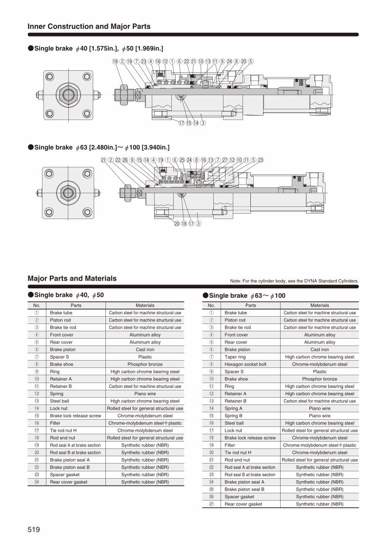
519
Parts
Brake tube
Piston rod
Brake tie rod
Front cover
Rear cover
Brake piston
Spacer S
Brake shoe
Ring
Retainer A
Retainer B
Spring
Steel ball
Lock nut
Brake lock release screw
Filter
Tie rod nut H
Rod end nut
Rod seal A at brake section
Rod seal B at brake section
Brake piston seal A
Brake piston seal B
Spacer gasket
Rear cover gasket
q
w
e
r
t
y
u
i
o
!0
!1
!2
!3
!4
!5
!6
!7
!8
!9
@0
@1
@2
@3
@4
No.
q
w
e
r
t
y
u
i
o
!0
!1
!2
!3
!4
!5
!6
!7
!8
!9
@0
@1
@2
@3
@4
Materials
Carbon steel for machine structural use
Carbon steel for machine structural use
Carbon steel for machine structural use
Aluminum alloy
Aluminum alloy
Cast iron
Plastic
Phosphor bronze
High carbon chrome bearing steel
High carbon chrome bearing steel
Carbon steel for machine structural use
Piano wire
High carbon chrome bearing steel
Rolled steel for general structural use
Chrome-molybdenum steel
Chrome-molybdenum steel+plastic
Chrome-molybdenum steel
Rolled steel for general structural use
Synthetic rubber (NBR)
Synthetic rubber (NBR)
Synthetic rubber (NBR)
Synthetic rubber (NBR)
Synthetic rubber (NBR)
Synthetic rubber (NBR)
Major Parts and Materials
Inner Construction and Major Parts
i@4 @0 t!1!3 o
!5!7 !4 e
@1@2 !0q!2 yr@3 !6!9w u!8
Parts
Brake tube
Piston rod
Brake tie rod
Front cover
Rear cover
Brake piston
Taper ring
Hexagon socket bolt
Spacer S
Brake shoe
Ring
Retainer A
Retainer B
Spring A
Spring B
Steel ball
Lock nut
Brake lock release screw
Filter
Tie rod nut H
Rod end nut
Rod seal A at brake section
Rod seal B at brake section
Brake piston seal A
Brake piston seal B
Spacer gasket
Rear cover gasket
q
w
e
r
t
y
u
i
o
!0
!1
!2
!3
!4
!5
!6
!7
!8
!9
@0
@1
@2
@3
@4
@5
@6
@7
No.
q
w
e
r
t
y
u
i
o
!0
!1
!2
!3
!4
!5
!6
!7
!8
!9
@0
@1
@2
@3
@4
@5
@6
@7
Materials
Carbon steel for machine structural use
Carbon steel for machine structural use
Carbon steel for machine structural use
Aluminum alloy
Aluminum alloy
Cast iron
High carbon chrome bearing steel
Chrome-molybdenum steel
Plastic
Phosphor bronze
High carbon chrome bearing steel
High carbon chrome bearing steel
Carbon steel for machine structural use
Piano wire
Piano wire
High carbon chrome bearing steel
Rolled steel for general structural use
Chrome-molybdenum steel
Chrome-molybdenum steel+plastic
Chrome-molybdenum steel
Rolled steel for general structural use
Synthetic rubber (NBR)
Synthetic rubber (NBR)
Synthetic rubber (NBR)
Synthetic rubber (NBR)
Synthetic rubber (NBR)
Synthetic rubber (NBR)
Single brake φ40 [1.575in.], φ50 [1.969in.]
Single brake φ40, φ50 Single brake φ63~φ100
@7u !2 !0!6i !3 t!1 @3
@0 !7!8 e
@5y @4!9r q!5o !4@2w @6@1
Single brake φ63 [2.480in.]~φ100 [3.940in.]
Note: For the cylinder body, see the DYNA Standard Cylinders.
514_523ダイナシリンダ_ENG 07.8.25 11:22 AM ページ519

520
Major Parts and Materials
Inner Construction and Major Parts
ti @2
!0
@4@3 !2
!6o !7!9 e
!5!3 !1q!4 yr!8 u@1w @5@0
Double brake φ40 [1.575in.], φ50 [1.969in.]
Double brake φ40, φ50 Double brake φ63~φ100
@5!8!7!0t@7@6!6!3i!5uy!4q
e@2 !1!2 !9 @0
o@1r@8@4w@3
Double brake φ63 [2.480in.]~φ100 [3.940in.]
Parts
Brake tube
Piston rod
Brake tie rod
Front cover
Rear cover
Brake piston
Spacer S
Spacer D
Brake shoe
Ring
Retainer A
Retainer B
Retainer D
Spring
Steel ball
Lock nut
Brake lock release screw
Filter
Tie rod nut H
Rod end nut
Rod seal A at brake section
Rod seal B at brake section
Brake piston seal A
Brake piston seal B
Spacer gasket
q
w
e
r
t
y
u
i
o
!0
!1
!2
!3
!4
!5
!6
!7
!8
!9
@0
@1
@2
@3
@4
@5
No.
q
w
e
r
t
y
u
i
o
!0
!1
!2
!3
!4
!5
!6
!7
!8
!9
@0
@1
@2
@3
@4
@5
Materials
Carbon steel for machine structural use
Carbon steel for machine structural use
Carbon steel for machine structural use
Aluminum alloy
Aluminum alloy
Cast iron
Plastic
Plastic
Phosphor bronze
High carbon chrome bearing steel
High carbon chrome bearing steel
Carbon steel for machine structural use
Carbon steel for machine structural use
Piano wire
High carbon chrome bearing steel
Rolled steel for general structural use
Chrome-molybdenum steel
Chrome-molybdenum steel+plastic
Chrome-molybdenum steel
Rolled steel for general structural use
Synthetic rubber (NBR)
Synthetic rubber (NBR)
Synthetic rubber (NBR)
Synthetic rubber (NBR)
Synthetic rubber (NBR)
Parts
Brake tube
Piston rod
Brake tie rod
Front cover
Rear cover
Brake piston
Taper ring
Hexagon socket bolt
Spacer S
Spacer D
Brake shoe
Ring
Retainer A
Retainer B
Retainer D
Steel ball
Spring A
Spring B
Lock nut
Brake lock release screw
Filter
Tie rod nut H
Rod end nut
Rod seal A at brake section
Rod seal B at brake section
Brake piston seal A
Brake piston seal B
Spacer gasket
q
w
e
r
t
y
u
i
o
!0
!1
!2
!3
!4
!5
!6
!7
!8
!9
@0
@1
@2
@3
@4
@5
@6
@7
@8
No.
q
w
e
r
t
y
u
i
o
!0
!1
!2
!3
!4
!5
!6
!7
!8
!9
@0
@1
@2
@3
@4
@5
@6
@7
@8
Materials
Carbon steel for machine structural use
Carbon steel for machine structural use
Carbon steel for machine structural use
Aluminum alloy
Aluminum alloy
Cast iron
High carbon chrome bearing steel
Chrome-molybdenum steel
Plastic
Plastic
Phosphor bronze
High carbon chrome bearing steel
High carbon chrome bearing steel
Carbon steel for machine structural use
Carbon steel for general structural use
High carbon chrome bearing steel
Piano wire
Piano wire
Rolled steel for general structural use
Chrome-molybdenum steel
Chrome-molybdenum steel+Plastic
Chrome-molybdenum steel
Rolled steel for general structural use
Synthetic rubber (NBR)
Synthetic rubber (NBR)
Synthetic rubber (NBR)
Synthetic rubber (NBR)
Synthetic rubber (NBR)
Note: For the cylinder body, see the DYNA Standard Cylinders.
DYNA
CYL
INDE
RS
514_523ダイナシリンダ_ENG 07.8.25 11:22 AM ページ520

521
Parts Rod seal for front cover
1
DRP16
DRP20
DRP20
DRP25
DRP30
Rod seal for rear cover
1
PNU16
PNU20
PNU20
PNU25A
PNU30
Piston seal A
1
PNU40
PNU53
PNU70
PNU85
PNU115
Piston seal B
1
PNU28
PNU32
GLY35
PNU45
PNU50
Spacer gasket
1
P22
P28
P28
P32
P40
Rear cover gasket
1
G45
G58
G75
G95
G120
QuantityBore size mm40
50
63
80
100
kg [lb.]
Seals
Bore sizemm [in.]
Zero stroke mass
Basic type Foot mounting type
Clevis mountingtype (with pin)
Head side flangemounting type
Rod side flangemounting type
Axial foot mounting type
Clevis mtg. type(w. supporting bkt.) Pivot mtg. type
2.21 [4.87](2.25 [4.96])3.62 [7.98]
(3.68 [8.11])5.68 [12.52]
(5.76 [12.70])8.97 [19.78]
(9.14 [20.15])14.69 [32.39]
(14.90 [32.85])
2.58 [5.69](2.62 [5.78])4.01 [8.84]
(4.07 [8.97])6.21 [13.69]
(6.29 [13.87])10.57 [23.31]
(10.74 [23.68])16.91 [37.29]
(17.12 [37.75])
2.38 [5.25](2.42 [5.34])3.85 [8.49]
(3.91 [8.62])6.06 [13.36]
(6.14 [13.54])9.44 [20.82]
(9.61 [21.19])15.25 [33.63]
(15.46 [34.09])
2.51 [5.53](2.55 [5.62])4.14 [9.13]
(4.20 [9.26])6.53 [14.40]
(6.61 [14.58])10.25 [22.60]
(10.42 [22.98])16.36 [36.07]
(16.57 [36.54])
2.60 [5.73](2.64 [5.82])4.15 [9.15]
(4.21 [9.28])7.28 [16.05]
(7.36 [16.23])11.19 [24.67]
(11.36 [25.05])17.56 [38.72]
(17.77 [39.18])
2.48 [5.47](2.52 [5.56])4.01 [8.84]
(4.07 [8.97])6.16 [13.58]
(6.24 [13.76])9.89 [21.81]
(10.06 [22.18])15.93 [35.13]
(16.14 [35.59])
3.18 [7.01](3.22 [7.10])4.71 [10.39]
(4.77 [10.52])6.86 [15.13]
(6.94 [15.30])10.61 [23.40]
(10.78 [23.77])16.65 [36.71]
(16.86 [37.18])
2.39 [5.27](2.43 [5.36])3.88 [8.56]
(3.94 [8.69])6.10 [13.45]
(6.18 [13.63])10.05 [22.16]
(10.22 [22.54])16.08 [35.46]
(16.29 [35.92])
0.00300 [0.00662](0.00431 [0.00950])0.00428 [0.00944]
(0.00635 [0.01400])0.00515 [0.01136]
(0.00773 [0.01704])0.00834 [0.01839]
(0.01302 [0.02871])0.01061 [0.02340]
(0.01642 [0.03621])
0.04 [0.09]
0.04 [0.09]
0.05[0.11]
0.16 [0.35]
0.21 [0.46]
0.21 [0.46]
0.62 [1.37]
1.24 [2.73]
0.27 [0.60]
0.34 [0.75]
0.34 [0.75]
0.87 [1.92]
1.47 [3.24]
0.06 [0.13]
Additional massfor each 1mm
[0.0394in.] stroke
Mass of 1 sensor switch [with holder] Mass of knuckleZCCSTNote CSF Y type knuckle
(with pin) I type knuckle
40 [1.575]
50 [1.969]
63 [2.480]
80 [3.150]
100 [3.940]
Mass
Parts Rod seal for front cover
1
Rod seal for rear cover
1
Piston seal B
2
Spacer gasket
1
DRP16
DRP20
DRP20
DRP25
DRP30
PNU16
PNU20
PNU20
PNU25A
PNU30
PNU28
PNU32
GLY35
PNU45
PNU50
Piston seal A
2
PNU40
PNU53
PNU70
PNU85
PNU115
P22
P28
P28
P32
P40
QuantityBore size mm40
50
63
80
100
Note: For lead wire length A (1000mm [39in.]).Remark: Figures in parentheses ( ) are for steel tube specification.
Calculation example: For basic type with bore size of 50mm, and stroke of 100mm,3.62+(0.00428×100)=4.048kg [8.924lb.]
kg [lb.]
Bore sizemm [in.]
Zero stroke mass
3.32 [7.32](3.36 [7.41])4.44 [9.79]
(4.50 [9.92])6.93 [15.28]
(7.01 [15.46])11.15 [24.59]
(11.32 [24.96])19.32 [42.60]
(19.53 [43.06])
3.49 [7.70](3.53 [7.78])4.67 [10.30]
(4.73 [10.43])7.31 [16.12]
(7.39 [16.29])11.62 [25.62]
(11.79 [26.00])19.88 [43.84]
(20.09 [44.30])
3.62 [7.98](3.66 [8.07])4.96 [10.94]
(5.02 [11.07])7.78 [17.15]
(7.86 [17.33])12.43 [27.41]
(12.60 [27.78])20.99 [46.28]
(21.20 [46.74])
3.71 [8.18](3.75 [8.27])4.97 [10.96]
(5.03 [11.09])8.53 [18.81]
(8.61 [18.99])13.37 [29.48]
(13.54 [29.86])22.19 [48.93]
(22.40 [49.39])
3.69 [8.14](3.73 [8.22])4.83 [10.65]
(4.89 [10.78])7.46 [16.45]
(7.54 [16.63])12.75 [28.11]
(12.92 [28.49])21.54 [47.49]
(21.75 [47.96])
3.59 [7.92](3.63 [8.00])4.83 [10.65]
(4.89 [10.78])7.41 [16.34]
(7.49 [16.52])12.07 [26.61]
(12.24 [26.99])20.56 [45.33]
(20.79 [45.84])
4.29 [9.46](4.33 [9.55])5.53 [12.19]
(5.59 [12.33])8.11 [17.88]
(8.19 [18.06])12.79 [28.20]
(12.96 [28.58])21.28 [46.92]
(21.49 [47.38])
3.50 [7.72](3.54 [7.81])4.70 [10.36]
(4.76 [10.50])7.35 [16.21]
(7.43 [16.38])12.23 [26.97]
(12.40 [27.34])20.71 [45.66]
(20.92 [46.13])
0.00300 [0.00662](0.00431 [0.00950])0.00428 [0.00944]
(0.00635 [0.01400])0.00515 [0.01136]
(0.00773 [0.01704])0.00834 [0.01839]
(0.01302 [0.02871])0.01061 [0.02340]
(0.01642 [0.03621])
0.04 [0.09]
0.04 [0.09]
0.05[0.11]
0.16 [0.35]
0.21 [0.46]
0.21 [0.46]
0.62 [1.37]
1.24 [2.73]
0.27 [0.60]
0.34 [0.75]
0.34 [0.75]
0.87 [1.92]
1.47 [3.24]
0.06 [0.13]
Additional massfor each 1mm
[0.0394in.] stroke
Mass of 1 sensor switch [with holder] Mass of knuckleZCCSTNote CSF Y type knuckle
(with pin) I type knuckle
40 [1.575]
50 [1.969]
63 [2.480]
80 [3.150]
100 [3.940]
Note: For lead wire length A (1000mm [39in.]).Remark: Figures in parentheses ( ) are for steel tube specification.
Calculation example: For basic type with bore size of 50mm, and stroke of 100mm,4.44+(0.00428×100)=4.868kg [10.732lb.]
Double brake
Single brake
Double brake
Single brake
Basic type Foot mounting type
Clevis mountingtype (with pin)
Head side flangemounting type
Rod side flangemounting type
Axial foot mounting type
Clevis mtg. type(w. supporting bkt.) Pivot mtg. type
514_523ダイナシリンダ_ENG 07.8.25 11:22 AM ページ521

522
A11+Stroke
C+StrokeB
GGZ2Z1F RT11
S11
φV
φD
11
When brake lock is released:X1
When brake is activated:X2 or more4‐L11
K(width across flats)
S
T
φD
N11 N N
M11
MQ
PP
4‐L2-Cushion needle2-Brake lock release screw
U
I
J
W
E
H 3
C11
2-O (Cylinder port)O11 (Brake releasing port)
40 [1.575]
50 [1.969]
63 [2.480]
80 [3.150]
100 [3.940]
40 [1.575]
50 [1.969]
63 [2.480]
80 [3.150]
100 [3.940]
A11
272
290
304
347
361
M
4
7
8
11
12
Code
Code
Dimensions of Single Brake, Basic Type (mm)
DDAR ×Bore size Stroke
B
49
57
63
75
75
C
93
93
96
108
108
C11
128
138
143
162
176
D
32
38
38
44
50
D11
38
38
44
50
60
E
39
47
47
59
59
F
10
10
16
16
16
G
31
31
32
36
36
H
21
29
29
37
37
I
22
27
27
32
36
J
8
11
11
13
14
K
M14×1.5
M18×1.5
M18×1.5
M22×1.5
M26×1.5
L
M6×1 Depth14
M6×1 Depth14
M8×1.25 Depth14
M10×1.5 Depth15
M10×1.5 Depth15
L11
M6×1 Depth14
M8×1.25 Depth14
M10×1.5 Depth15
M10×1.5 Depth15
M12×1.75 Depth15
M11
6
11
15
15
15
N
18
18
18
20
20
N11
17
17
22
24
24
O
Rc1/4
Rc3/8
Rc3/8
Rc1/2
Rc1/2
O11
Rc1/4
Rc1/4
Rc1/4
Rc3/8
Rc3/8
P
25.5
24
25
29
29
Q
10
12
12
16
18
R
2
2
2
2
2
S
50
62
75
94
112
S11
62
75
94
112
138
T
37
47
56
70
84
T11
47
56
70
84
104
U
12
14
15
18
17
V
16
20
20
25
30
W
14
17
17
21
26
X1
88
97
114
134
159
X2
94
104
122
142
166
Z1
27
30
35
35
36
Z2
28
30
35
39
39
DDAR Bore size
Bore mm [in.]
Bore mm [in.]
DYNA
CYL
INDE
RS
514_523ダイナシリンダ_ENG 07.8.25 11:22 AM ページ522

523
AG2 AG2
AC6+Stroke
AA6+Stroke
AD2 AD2AF2
AE2
AF2
AE3
AT
2
AS
3AS
2
AH
2
AT
2
4-φAP
AB2
A11+Stroke
C+StrokeB
GGZ2Z1F RT11
S11
φV
φD
11K
S
T
U
I
J
E
H 3
C11
(width across flats)W
FD3 FG2 FD2FG2
FC6+Stroke
FA6+Stroke
FF2
FE2
FF2
FE2
FS
3
FH
2
FT
3
FS
2
FT
2
4-φFP2
FB2
A11+Stroke
C+StrokeB
GGZ2Z1F RT11
S11
φV
K
S
T
U
I
J
E
H 3
C11
(width across flats)
W
40 [1.575]
50 [1.969]
63 [2.480]
80 [3.150]
100 [3.940]
40 [1.575]
50 [1.969]
63 [2.480]
80 [3.150]
100 [3.940]
A11
272
290
304
347
361
B
49
57
63
75
75
C
93
93
96
108
108
C11
128
138
143
162
176
D11
38
38
44
50
60
E
39
47
47
59
59
F
10
10
16
16
16
G
31
31
32
36
36
H
21
29
29
37
37
I
22
27
27
32
36
J
8
11
11
13
14
K
M14×1.5
M18×1.5
M18×1.5
M22×1.5
M26×1.5
Code
Code R
2
2
2
2
2
S
50
62
75
94
112
S11
62
75
94
112
138
T
37
47
56
70
84
T11
47
56
70
84
104
U
12
14
15
18
17
V
16
20
20
25
30
W
14
17
17
21
26
Z1
27
30
35
35
36
Z2
28
30
35
39
39
AA6
297
311
335
366
406
AB2
23
29
29
41
32
AC6
273
287
307
338
370
AD2
12
12
14
14
18
AE2
70
80
97
114
138
AE3
60
70
80
97
114
AF2
37
47
56
70
84
AG2
26
28
34
34
43
AH2
41
48
59
66
79
AP
12
12
14
14
14
AS2
72
85.5
106
122
148
AS3
66
79
96.5
113
135
AT2
6
6
8
8
10
40 [1.575]
50 [1.969]
63 [2.480]
80 [3.150]
100 [3.940]
40 [1.575]
50 [1.969]
63 [2.480]
80 [3.150]
100 [3.940]
A11
272
290
304
347
361
B
49
57
63
75
75
C
93
93
96
108
108
C11
128
138
143
162
176
E
39
47
47
59
59
F
10
10
16
16
16
G
31
31
32
36
36
H
21
29
29
37
37
I
22
27
27
32
36
J
8
11
11
13
14
K
M14×1.5
M18×1.5
M18×1.5
M22×1.5
M26×1.5
R
2
2
2
2
2
Code
Code S
50
62
75
94
112
S11
62
75
94
112
138
T
37
47
56
70
84
T11
47
56
70
84
104
U
12
14
15
18
17
V
16
20
20
25
30
W
14
17
17
21
26
Z1
27
30
35
35
36
Z2
28
30
35
39
39
FA6
248
262
276
315
336
FB2
59
67
76
88
89
FC6
201
211
213
244
257
FD2
22
24
29
33
37
FD3
25
27
34
38
42
FE2
105
117
147
168
195
FF2
83
95
121
140
167
FG2
14
14
18
18
18
FH2
31
38
47
57
69
FP2
12
12
14
14
14
FS2
56
69
84.5
104
125
FS3
62
75.5
94
113
138
FT2
5.5
6.5
8.5
9.5
11.5
FT3
9
9
13
14
16
Dimensions of Single Brake, Foot Mounting Type (mm)
Dimensions of Single Brake, Axial Foot Mounting Type (mm)
DDAR ×Bore size Stroke -1
DDAR ×Bore size Stroke -2
Bore mm [in.]
Bore mm [in.]
Bore mm [in.]
Bore mm [in.]
514_523ダイナシリンダ_ENG 07.8.25 11:22 AM ページ523

524
Dimensions of Single Brake, Rod Side Flange Mounting Type (mm)
Dimensions of Single Brake, Head Side Flange Mounting Type (mm)
DDAR ×Bore size Stroke -3
DDAR ×Bore size Stroke -5
BD
BC
BF
BE
BB
4-φBP
BG3+Stroke
C+StrokeB
GGZ2Z1FT11
S11
φV
φD
11
4‐L11
K
T
U
I
J
E
H 3
C11
(width across flats)W
BF2
BE2
BB2BA2
A11+Stroke
BD
2
BC
2
4-φBP2
A11+Stroke
C+StrokeB
GGZ2Z1 RT11
φV
K
S
S11
T
U
I
J
H 3
C11
(width across flats)
W
φD
4‐L
40 [1.575]
50 [1.969]
63 [2.480]
80 [3.150]
100 [3.940]
40 [1.575]
50 [1.969]
63 [2.480]
80 [3.150]
100 [3.940]
A11
272
290
304
347
361
B
49
57
63
75
75
C
93
93
96
108
108
C11
128
138
143
162
176
D
32
38
38
44
50
G
31
31
32
36
36
H
21
29
29
37
37
I
22
27
27
32
36
J
8
11
11
13
14
K
M14×1.5
M18×1.5
M18×1.5
M22×1.5
M26×1.5
L
M6×1 Depth 14
M6×1 Depth 14
M8×1.25 Depth 14
M10×1.5 Depth 15
M10×1.5 Depth 15
Code
Code R
2
2
2
2
2
S
50
62
75
94
112
S11
62
75
94
112
138
T
37
47
56
70
84
T11
47
56
70
84
104
U
12
14
15
18
17
V
16
20
20
25
30
W
14
17
17
21
26
Z1
27
30
35
35
36
Z2
28
30
35
39
39
BA2
39
47
47
59
59
BB2
10
10
16
16
16
BC2
65
76
95
115
138
BD2
47
56
70
84
104
BE2
104
116
143
162
196
BF2
86
98
119
138
168
BP2
9
9
12
12
14
40 [1.575]
50 [1.969]
63 [2.480]
80 [3.150]
100 [3.940]
40 [1.575]
50 [1.969]
63 [2.480]
80 [3.150]
100 [3.940]
B
49
57
63
75
75
Code
Code
C
93
93
96
108
108
C11
128
138
143
162
176
D11
38
38
44
50
60
E
39
47
47
59
59
F
10
10
16
16
16
G
31
31
32
36
36
H
21
29
29
37
37
I
22
27
27
32
36
J
8
11
11
13
14
K
M14×1.5
M18×1.5
M18×1.5
M22×1.5
M26×1.5
L11
M6×1 Depth 14
M8×1.25 Depth 14
M10×1.5 Depth 15
M10×1.5 Depth 15
M12×1.75 Depth 15
S11
62
75
94
112
138
T
37
47
56
70
84
T11
47
56
70
84
104
U
12
14
15
18
17
V
16
20
20
25
30
W
14
17
17
21
26
Z1
27
30
35
35
36
Z2
28
30
35
39
39
BB
10
10
10
16
16
BC
52
65
76
95
115
BD
36
47
56
70
84
BE
84
104
116
143
162
BF
70
86
98
119
138
BG3
280
298
312
361
375
BP
7
9
9
12
12
Bore mm [in.]
Bore mm [in.]
Bore mm [in.]
Bore mm [in.]
DYNA
CYL
INDE
RS
524_539ダイナシリンダ_ENG 07.8.25 11:24 AM ページ524

525
With Supporting Bracket
Dimensions of Single Brake, Clevis Mounting Type (mm)
DDAR ×Bore size Stroke -7
DDAR -7-7C×Bore size Stroke
GGGH GH
GDGC
GB
GA3+Stroke
GF
GE
GJ
GI
GT
4‐φGP
GK
φCEH9/f8
CD
CF
CC
CJ
PA1
CT CT
CP
CA3+Stroke
CB3+Stroke +0.7+0.5
C+StrokeB
GGZ2Z1FT11
S11
φV
φD
11
4‐L11
K
S
T
U
I
J
E
H 3
C11
(width across flats)W
40 [1.575]
50 [1.969]
63 [2.480]
80 [3.150]
100 [3.940]
40 [1.575]
50 [1.969]
63 [2.480]
80 [3.150]
100 [3.940]
B
49
57
63
75
75
Code
Code
C
93
93
96
108
108
C11
128
138
143
162
176
D11
38
38
44
50
60
E
39
47
47
59
59
F
10
10
16
16
16
G
31
31
32
36
36
H
21
29
29
37
37
I
22
27
27
32
36
J
8
11
11
13
14
K
M14×1.5
M18×1.5
M18×1.5
M22×1.5
M26×1.5
L11
M6×1 Depth 14
M8×1.25 Depth 14
M10×1.5 Depth 15
M10×1.5 Depth 15
M12×1.75 Depth 15
S
50
62
75
94
112
S11
62
75
94
112
138
T
37
47
56
70
84
T11
47
56
70
84
104
U
12
14
15
18
17
V
16
20
20
25
30
W
14
17
17
21
26
Z1
27
30
35
35
36
Z2
28
30
35
39
39
CA3
302
322
336
398
412
CB3
289
307
321
377
391
CC
19
19
19
32
32
CD
R15
R17
R17
R24
R24
CE
14
14
14
20
20
CF
R17
R17
R17
R30
R30
CJ
13
15
15
21
21
CP
20
20
20
32
32
CT
12.5
16.5
16.5
17.5
17.5
PA1
58
66
66
78
78
40 [1.575]
50 [1.969]
63 [2.480]
80 [3.150]
100 [3.940]
GA3
355.5
373.5
387.5
463.5
477.5
Code GB
66.5
66.5
66.5
86.5
86.5
GC
12.5
12.5
12.5
20.5
20.5
GD
73
73
73
98
98
GE
105
105
105
135
135
GF
80
80
80
105
105
GG
40
40
40
65
65
GH
16.5
16.5
16.5
16.5
16.5
GI
70
76
82.5
107
116
GJ
45
45
45
60
60
GK
76
82.5
92
116
129
GP
11(Thru hole)
11(Thru hole)
11(Thru hole)
14(Thru hole)
14(Thru hole)
GT
8
8
8
12
12
Bore mm [in.]
Bore mm [in.]
Bore mm [in.]
524_539ダイナシリンダ_ENG 07.8.25 11:24 AM ページ525

526
DQ
φDEH9
DD
DF
DC
DJDB3+Stroke
DA3+Stroke
C+StrokeB
GGZ2Z1FT11
S11
φV
φD
11
4‐L11
K
S
T
U
I
J
E
H 3
C11
(width across flats)W
Dimensions of Single Brake, Pivot Mounting Type (mm)
DDAR ×Bore size Stroke -8
40 [1.575]
50 [1.969]
63 [2.480]
80 [3.150]
100 [3.940]
40 [1.575]
50 [1.969]
63 [2.480]
80 [3.150]
100 [3.940]
B
49
57
63
75
75
Code
Code
C
93
93
96
108
108
C11
128
138
143
162
176
D11
38
38
44
50
60
E
39
47
47
59
59
F
10
10
16
16
16
G
31
31
32
36
36
H
21
29
29
37
37
I
22
27
27
32
36
J
8
11
11
13
14
K
M14×1.5
M18×1.5
M18×1.5
M22×1.5
M26×1.5
L11
M6×1 Depth 14
M8×1.25 Depth 14
M10×1.5 Depth 15
M10×1.5 Depth 15
M12×1.75 Depth 15
S
50
62
75
94
112
S11
62
75
94
112
138
T
37
47
56
70
84
T11
47
56
70
84
104
U
12
14
15
18
17
V
16
20
20
25
30
W
14
17
17
21
26
Z1
27
30
35
35
36
Z2
28
30
35
39
39
DA3
303
321
335
398
411
DB3
289
307
321
377
391
DC
19
19
19
32
32
DD
R17
R17
R17
R24
R24
DE
14
14
14
20
20
DF
R17
R17
R17
R25
R26
DJ
14
14
14
21
20
DQ
20
20
20
32
32
–0–0.084–0–0.084–0–0.084–0–0.100–0–0.100
Bore mm [in.]
Bore mm [in.]
DYNA
CYL
INDE
RS
524_539ダイナシリンダ_ENG 07.8.25 11:24 AM ページ526

527
40 [1.575]
50 [1.969]
63 [2.480]
80 [3.150]
100 [3.940]
40 [1.575]
50 [1.969]
63 [2.480]
80 [3.150]
100 [3.940]
A12
350
374
383
439
467
M
4
7
8
11
12
Code
Code
B
49
57
63
75
75
C
93
93
96
108
108
C12
206
222
222
254
282
D
32
38
38
44
50
D12
38
38
44
50
60
E
39
47
47
59
59
F
10
10
16
16
16
G
31
31
32
36
36
H
21
29
29
37
37
I
22
27
27
32
36
J
8
11
11
13
14
K
M14×1.5
M18×1.5
M18×1.5
M22×1.5
M26×1.5
L
M6×1 Depth14
M6×1 Depth14
M8×1.25 Depth14
M10×1.5 Depth15
M10×1.5 Depth15
L12
M6×1 Depth14
M8×1.25 Depth14
M10×1.5 Depth15
M10×1.5 Depth15
M12×1.75 Depth15
N
18
18
18
20
20
N12
116
124
124
143
157
O
Rc1/4
Rc3/8
Rc3/8
Rc1/2
Rc1/2
O12
Rc1/4
Rc1/4
Rc1/4
Rc3/8
Rc3/8
P
25.5
24
25
29
29
Q
10
12
12
16
18
R
2
2
2
2
2
S
50
62
75
94
112
S12
62
75
94
112
138
T
37
47
56
70
84
T12
47
56
70
84
104
U
12
14
15
18
17
V
16
20
20
25
30
W
14
17
17
21
26
X1
88
97
114
134
159
X2
94
104
122
142
166
YT
37.5
44
53.5
68.5
82
Z1
27
30
35
35
36
Z2
53
56
61
67
68
B
H 3
GGZ1F RT12
S12
φV
φD
12
When brake lock is released:X1
When brake is activated:X2 or more4‐L12
K(width across flats)
S
T
φD
N N2‐O
MQ
PP
4‐L2‐Cushion needle4-Brake lock release screw
C12
A12+Stroke
Z2U U
N12
O12
YT
I
J
W
E
C+Stroke
(Cylinder port)
(Brake releasing port)
Dimensions of Double Brake, Basic Type (mm)
DDARR ×Bore size Stroke DDARR Bore size
Bore mm [in.]
Bore mm [in.]
524_539ダイナシリンダ_ENG 07.8.25 11:24 AM ページ527
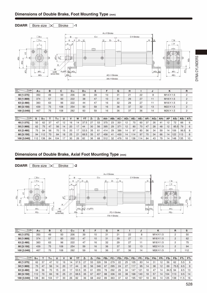
528
Dimensions of Double Brake, Foot Mounting Type (mm)
Dimensions of Double Brake, Axial Foot Mounting Type (mm)
DDARR ×Bore size Stroke -1
DDARR ×Bore size Stroke -2
FD3 FG2 FD2FG2
FC7+Stroke
FA7+Stroke
FF2
FE2
FF2
FE2
FS
3
FH
2
FT
3
FS
2
FT
2
4-φFP2
FB2
B
H 3
GGZ1F RT12
S12
φV
S
T
C12
A12+Stroke
Z2U U
YT
I
J
E
C+Stroke
K
(width across flats)
W
AG2 AG2
AC7+Stroke
AA7+Stroke
AD2 AD2AF2
AE2
AF2
AE3
AT
2
AS
3AS
2
AH
2
AT
2
AB2
4-φAP
B
H 3
GGZ1F RT12
S12
φV
φD
12
S
T
C12
A12+Stroke
Z2U U
YT
I
J
E
C+Stroke
K
(width across flats)
W
40 [1.575]
50 [1.969]
63 [2.480]
80 [3.150]
100 [3.940]
Code S
50
62
75
94
112
S12
62
75
94
112
138
T
37
47
56
70
84
T12
47
56
70
84
104
U
12
14
15
18
17
V
16
20
20
25
30
W
14
17
17
21
26
YT
37.5
44
53.5
68.5
82
Z1
27
30
35
35
36
Z2
53
56
61
67
68
AA7
375
395
414
458
512
AB2
23
29
29
41
32
AC7
351
371
386
430
476
AD2
12
12
14
14
18
AE2
70
80
97
114
138
AE3
60
70
80
97
114
AF2
37
47
56
70
84
AG2
26
28
34
34
43
AH2
41
48
59
66
79
AP
12
12
14
14
14
AS2
72
85.5
106
122
148
AS3
66
79
96.5
113
135
AT2
6
6
8
8
10
40 [1.575]
50 [1.969]
63 [2.480]
80 [3.150]
100 [3.940]
A12
350
374
383
439
467
Code B
49
57
63
75
75
C
93
93
96
108
108
C12
206
222
222
254
282
D12
38
38
44
50
60
E
39
47
47
59
59
F
10
10
16
16
16
G
31
31
32
36
36
H
21
29
29
37
37
I
22
27
27
32
36
J
8
11
11
13
14
K
M14×1.5
M18×1.5
M18×1.5
M22×1.5
M26×1.5
R
2
2
2
2
2
40 [1.575]
50 [1.969]
63 [2.480]
80 [3.150]
100 [3.940]
A12
350
374
383
439
467
B
49
57
63
75
75
C
93
93
96
108
108
C12
206
222
222
254
282
E
39
47
47
59
59
F
10
10
16
16
16
G
31
31
32
36
36
H
21
29
29
37
37
I
22
27
27
32
36
J
8
11
11
13
14
K
M14×1.5
M18×1.5
M18×1.5
M22×1.5
M26×1.5
R
2
2
2
2
2
S
50
62
75
94
112
Code
40 [1.575]
50 [1.969]
63 [2.480]
80 [3.150]
100 [3.940]
Code S12
62
75
94
112
138
T
37
47
56
70
84
T12
47
56
70
84
104
U
12
14
15
18
17
V
16
20
20
25
30
W
14
17
17
21
26
YT
37.5
44
53.5
68.5
82
Z1
27
30
35
35
36
Z2
53
56
61
67
68
FA7
326
346
355
407
442
FB2
59
67
76
88
89
FC7
279
295
292
336
363
FD2
22
24
29
33
37
FD3
25
27
34
38
42
FE2
105
117
147
168
195
FF2
83
95
121
140
167
FG2
14
14
18
18
18
FH2
31
38
47
57
69
FP2
12
12
14
14
14
FS2
56
69
84.5
104
125
FS3
62
75.5
94
113
138
FT2
5.5
6.5
8.5
9.5
11.5
FT3
9
9
13
14
16
Bore mm [in.]
Bore mm [in.]
Bore mm [in.]
Bore mm [in.]
DYNA
CYL
INDE
RS
524_539ダイナシリンダ_ENG 07.8.25 11:24 AM ページ528

529
Dimensions of Double Brake, Rod Side Flange Mounting Type (mm)
Dimensions of Double Brake, Head Side Flange Mounting Type (mm)
DDARR ×Bore size Stroke -3
DDARR ×Bore size Stroke -5
4-φBP2
BF2
BE2
BB2BA2
BD
2
BC
2
B
H 3
GGZ1 RT12
φV
S
S12
T
C12
A12+Stroke
Z2U U
YT
I
J
C+Stroke
K
(width across flats)
W
φD
4‐L
BD
BC
BF
BE
BB
4-φBP
BG4+Stroke
B
H 3
GGZ1FT12
S12
φV
φD
12
T
C12
Z2U U
YT
I
J
E
C+Stroke
4‐L12
K
(width across flats)W
40 [1.575]
50 [1.969]
63 [2.480]
80 [3.150]
100 [3.940]
40 [1.575]
50 [1.969]
63 [2.480]
80 [3.150]
100 [3.940]
A12
350
374
383
439
467
Code
Code
B
49
57
63
75
75
C
93
93
96
108
108
C12
206
222
222
254
282
D
32
38
38
44
50
G
31
31
32
36
36
H
21
29
29
37
37
I
22
27
27
32
36
J
8
11
11
13
14
K
M14×1.5
M18×1.5
M18×1.5
M22×1.5
M26×1.5
L
M6×1 Depth 14
M6×1 Depth 14
M8×1.25 Depth 14
M10×1.5 Depth 15
M10×1.5 Depth 15
R
2
2
2
2
2
S
50
62
75
94
112
S12
62
75
94
112
138
T
37
47
56
70
84
T12
47
56
70
84
104
U
12
14
15
18
17
V
16
20
20
25
30
W
14
17
17
21
26
YT
37.5
44
53.5
68.5
82
Z1
27
30
35
35
36
Z2
53
56
61
67
68
BA2
39
47
47
59
59
BB2
10
10
16
16
16
BC2
65
76
95
115
138
BD2
47
56
70
84
104
BE2
104
116
143
162
196
BF2
86
98
119
138
168
BP2
9
9
12
12
14
40 [1.575]
50 [1.969]
63 [2.480]
80 [3.150]
100 [3.940]
40 [1.575]
50 [1.969]
63 [2.480]
80 [3.150]
100 [3.940]
B
49
57
63
75
75
Code
Code
C
93
93
96
108
108
C12
206
222
222
254
282
D12
38
38
44
50
60
E
39
47
47
59
59
F
10
10
16
16
16
G
31
31
32
36
36
H
21
29
29
37
37
I
22
27
27
32
36
J
8
11
11
13
14
K
M14×1.5
M18×1.5
M18×1.5
M22×1.5
M26×1.5
L12
M6×1 Depth 14
M8×1.25 Depth 14
M10×1.5 Depth 15
M10×1.5 Depth 15
M12×1.75 Depth 15
S12
62
75
94
112
138
T
37
47
56
70
84
T12
47
56
70
84
104
U
12
14
15
18
17
V
16
20
20
25
30
W
14
17
17
21
26
YT
37.5
44
53.5
68.5
82
Z1
27
30
35
35
36
Z2
53
56
61
67
68
BB
10
10
10
16
16
BC
52
65
76
95
115
BD
36
47
56
70
84
BE
84
104
116
143
162
BF
70
86
98
119
138
BG4
358
382
391
453
481
BP
7
9
9
12
12
Bore mm [in.]
Bore mm [in.]
Bore mm [in.]
Bore mm [in.]
524_539ダイナシリンダ_ENG 07.8.25 11:24 AM ページ529

530
Dimensions of Double Brake, Clevis Mounting Type (mm)
DDARR ×Bore size Stroke -7
With Supporting Bracket DDARR -7-7C×Bore size Stroke
CC
CJ
CA4+Stroke
CB4+Stroke
PA1
CT CT
CP+0.7+0.5
φCEH9/f8
CD
CF
B
H 3
GZ1FT12
S12
φV
φD
12
C12
Z2U U
YT
I
J
E
C+Stroke
G S
T4‐L12
K
(width across flats)W
GGGH GH
GDGC
GB
GA4+Stroke
GF
GE
GJ
GI
GT
4‐φGP
GK
2
40 [1.575]
50 [1.969]
63 [2.480]
80 [3.150]
100 [3.940]
40 [1.575]
50 [1.969]
63 [2.480]
80 [3.150]
100 [3.940]
B
49
57
63
75
75
Code
Code
C
93
93
96
108
108
C12
206
222
222
254
282
D12
38
38
44
50
60
E
39
47
47
59
59
F
10
10
16
16
16
G
31
31
32
36
36
H
21
29
29
37
37
I
22
27
27
32
36
J
8
11
11
13
14
K
M14×1.5
M18×1.5
M18×1.5
M22×1.5
M26×1.5
L12
M6×1 Depth 14
M8×1.25 Depth 14
M10×1.5 Depth 15
M10×1.5 Depth 15
M12×1.75 Depth 15
S
50
62
75
94
112
S12
62
75
94
112
138
T
37
47
56
70
84
T12
47
56
70
84
104
U
12
14
15
18
17
V
16
20
20
25
30
W
14
17
17
21
26
YT
37.5
44
53.5
68.5
82
Z1
27
30
35
35
36
Z2
53
56
61
67
68
CA4
380
406
415
490
518
CB4
367
391
400
469
497
CC
19
19
19
32
32
CD
R15
R17
R17
R24
R24
CE
14
14
14
20
20
CF
R17
R17
R17
R30
R30
CJ
13
15
15
21
21
CP
20
20
20
32
32
CT
12.5
16.5
16.5
17.5
17.5
PA1
58
66
66
78
78
40 [1.575]
50 [1.969]
63 [2.480]
80 [3.150]
100 [3.940]
GA4
433.5
457.5
466.5
555.5
583.5
Code GB
66.5
66.5
66.5
86.5
86.5
GC
12.5
12.5
12.5
20.5
20.5
GD
73
73
73
98
98
GE
105
105
105
135
135
GF
80
80
80
105
105
GG
40
40
40
65
65
GH
16.5
16.5
16.5
16.5
16.5
GI
70
76
82.5
107
116
GJ
45
45
45
60
60
GK2
82.5
89
98.5
128.5
142
GP
11(Thru hole)
11(Thru hole)
11(Thru hole)
14(Thru hole)
14(Thru hole)
GT
8
8
8
12
12
Bore mm [in.]
Bore mm [in.]
Bore mm [in.]
DYNA
CYL
INDE
RS
524_539ダイナシリンダ_ENG 07.8.25 11:24 AM ページ530

531
Dimensions of Double Brake, Pivot Mounting Type (mm)
DDARR ×Bore size Stroke -8
φDEH9
DD
DF
DQDC
DJDB4+Stroke
DA4+Stroke
B
H 3
GGZ1FT12
S12
φV
φD
12
S
T
C12
Z2U U
YT
I
J
E
C+Stroke
4‐L12
K
(width across flats)W
40 [1.575]
50 [1.969]
63 [2.480]
80 [3.150]
100 [3.940]
40 [1.575]
50 [1.969]
63 [2.480]
80 [3.150]
100 [3.940]
B
49
57
63
75
75
Code
Code
C
93
93
96
108
108
C12
206
222
222
254
282
D12
38
38
44
50
60
E
39
47
47
59
59
F
10
10
16
16
16
G
31
31
32
36
36
H
21
29
29
37
37
I
22
27
27
32
36
J
8
11
11
13
14
K
M14×1.5
M18×1.5
M18×1.5
M22×1.5
M26×1.5
L12
M6×1 Depth 14
M8×1.25 Depth 14
M10×1.5 Depth 15
M10×1.5 Depth 15
M12×1.75 Depth 15
S
50
62
75
94
112
S12
62
75
94
112
138
T
37
47
56
70
84
T12
47
56
70
84
104
U
12
14
15
18
17
V
16
20
20
25
30
W
14
17
17
21
26
YT
37.5
44
53.5
68.5
82
Z1
27
30
35
35
36
Z2
53
56
61
67
68
DA4
381
405
414
490
517
DB4
367
391
400
469
497
DC
19
19
19
32
32
DD
R17
R17
R17
R24
R24
DE
14
14
14
20
20
DF
R17
R17
R17
R25
R26
DJ
14
14
14
21
20
DQ
20
20
20
32
32
Bore mm [in.]
Bore mm [in.]
–0–0.084–0–0.084–0–0.084–0–0.100–0–0.100
524_539ダイナシリンダ_ENG 07.8.25 11:24 AM ページ531

Lead wire length(Applicable to other than CSF only)A 1000mm [39in.]B 3000mm [118in.]
532
Symbol
DYNA cylinder sensor switches come in 2 types, and 2 corresponding types of mounting holders are available. See the following for details.
For details of sensor switches, see p.1544.
Sensor switch modelZC130 2-lead wire Solid state type with indicator lamp
DC10~28VZC153 3-lead wire Solid state type with indicator lamp
DC4.5~28VCS5T 2-lead wire Reed switch type without indicator lamp
DC5~28V, AC85~115VCS11T 2-lead wire Reed switch type with indicator lamp
DC10~28VCS2F DIN connector Reed switch type with indicator lamp
AC85~230VCS3F DIN connector Reed switch type with indicator lamp
DC10~30VCS4F DIN connector Reed switch type with indicator lamp
DC10~30VCS5F DIN connector Reed switch type without indicator lamp
DC3~30V
Order Codes
Sensor Switches and Mounting Holders
Without mounting holder Order codes for mounting holders onlyAZC130
-
Sensor typeC1: Solid state type
for ZC1Reed switch typefor CST
DF: Reed switch typefor CSF
With mounting holder AZC130 40NDDA
NDDA: Applicable to other than CSFNDF : Applicable to CSF only
Bore size
-C1 40NDDA
NDDA: Applicable to otherthan CSF
Blank : For CSF
Solid state type ZC130ZC153
Reed switch type CS5TCS11T
DIN connector CS2FCS3FCS4FCS5F
Bore size32 For φ32
[1.260in.]40 For φ40
[1.575in.]50 For φ50
[1.969in.]63 For φ63
[2.480in.]80 For φ80
[3.150in.]100 For φ100
[3.940in.]125 For φ125
[4.921in.]
SENSOR SWITCHES
DYNA
CYL
INDE
RS
524_539ダイナシリンダ_ENG 07.8.25 11:24 AM ページ532
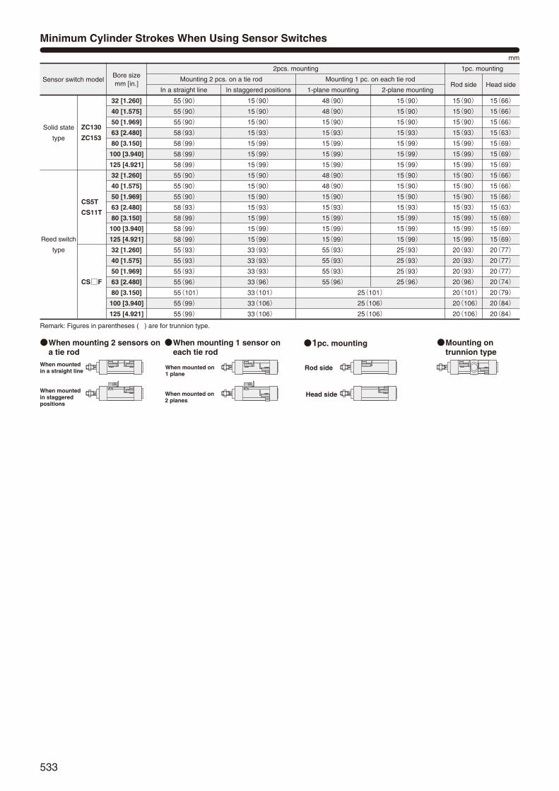
533
Solid state
type
Sensor switch modelBore sizemm [in.]
32 [1.260]
40 [1.575]
50 [1.969]
63 [2.480]
80 [3.150]
100 [3.940]
125 [4.921]
32 [1.260]
40 [1.575]
50 [1.969]
63 [2.480]
80 [3.150]
100 [3.940]
125 [4.921]
32 [1.260]
40 [1.575]
50 [1.969]
63 [2.480]
80 [3.150]
100 [3.940]
125 [4.921]
55(90)
55(90)
55(90)
58(93)
58(99)
58(99)
58(99)
55(90)
55(90)
55(90)
58(93)
58(99)
58(99)
58(99)
55(93)
55(93)
55(93)
55(96)
55(101)
55(99)
55(99)
15(90)
15(90)
15(90)
15(93)
15(99)
15(99)
15(99)
15(90)
15(90)
15(90)
15(93)
15(99)
15(99)
15(99)
33(93)
33(93)
33(93)
33(96)
33(101)
33(106)
33(106)
48(90)
48(90)
15(90)
15(93)
15(99)
15(99)
15(99)
48(90)
48(90)
15(90)
15(93)
15(99)
15(99)
15(99)
55(93)
55(93)
55(93)
55(96)
25(101)
25(106)
25(106)
15(90)
15(90)
15(90)
15(93)
15(99)
15(99)
15(99)
15(90)
15(90)
15(90)
15(93)
15(99)
15(99)
15(99)
25(93)
25(93)
25(93)
25(96)
15(90)
15(90)
15(90)
15(93)
15(99)
15(99)
15(99)
15(90)
15(90)
15(90)
15(93)
15(99)
15(99)
15(99)
20(93)
20(93)
20(93)
20(96)
20(101)
20(106)
20(106)
15(66)
15(66)
15(66)
15(63)
15(69)
15(69)
15(69)
15(66)
15(66)
15(66)
15(63)
15(69)
15(69)
15(69)
20(77)
20(77)
20(77)
20(74)
20(79)
20(84)
20(84)
2pcs. mounting 1pc. mounting
mm
Rod side Head sideMounting 2 pcs. on a tie rod
In a straight line In staggered positions
Mounting 1 pc. on each tie rod
1-plane mounting 2-plane mounting
ZC130
ZC153
CS5T
CS11T
CSF
Reed switch
type
Minimum Cylinder Strokes When Using Sensor Switches
Remark: Figures in parentheses ( ) are for trunnion type.
When mounting 2 sensors ona tie rod
When mountedin a straight line
When mountedin staggeredpositions
When mounted on1 plane
When mounted on2 planes
Rod side
Head side
When mounting 1 sensor oneach tie rod
1pc. mounting Mounting ontrunnion type
524_539ダイナシリンダ_ENG 07.8.25 11:24 AM ページ533

A BA B
Approx.1.5mm
A
ZC130
ZC153
CS5T
CS11T
CSF
Solid statetype
40
A
B
A
B
A
B
A
B
9[0.354]
5[0.197]
10.5[0.413]
6.5[0.256]
7[0.276]
3[0.118]
3.5[0.138]
0
9[0.354]
5[0.197]
10.5[0.413]
6.5[0.256]
7[0.276]
3[0.118]
3.5[0.138]
0
32
9[0.354]
5[0.197]
10.5[0.413]
6.5[0.256]
7[0.276]
3[0.118]
3.5[0.138]
0
9.5[0.374]
5.5[0.217]
11[0.433]
7[0.276]
7.5[0.295]
3.5[0.138]
4[0.157]
0
12.5[0.492]
6.5[0.256]
14[0.551]
8[0.315]
10.5[0.413]
4.5[0.177]
7[0.276]
1[0.039]
12.5[0.492]
6.5[0.256]
14[0.551]
8[0.315]
10.5[0.413]
4.5[0.177]
7[0.276]
1[0.039]
50 63 80 100
14.5[0.571]
10.5[0.413]
16[0.630]
12[0.472]
12.5[0.492]
8.5[0.335]
9[0.354]
5[0.197]
125
Reed switchtype
Caution: The reed sensor switch cannot be mounted on the head side in anydirection other than that shown in the diagram.
Bore sizeCodeSensor switch model
mm [in.]
Mounting Location of Sensor Switch
When the sensor switch is mounted in the locations shown in the diagram(figures in the table are reference values), the magnet comes to the sensorswitch’s maximum sensing location at the end of the stroke.
ZC130
ZC153
CS5T
CS11T
CSF
Solid statetype
40
A
B
A
B
A
B
A
B
9[0.354]
5[0.197]
10.5[0.413]
6.5[0.256]
7[0.276]
3[0.118]
3.5[0.138]
0
9.5[0.374]
4.5[0.177]
11[0.433]
6[0.236]
7.5[0.295]
2.5[0.098]
4[0.157]
0
32
9.5[0.374]
4.5[0.177]
11[0.433]
6[0.236]
7.5[0.295]
2.5[0.098]
4[0.157]
0
9.5[0.374]
5.5[0.217]
11[0.433]
7[0.276]
7.5[0.295]
3.5[0.138]
4[0.157]
0
12.5[0.492]
6.5[0.256]
14[0.551]
8[0.315]
10.5[0.413]
4.5[0.177]
7[0.276]
1[0.039]
12.5[0.492]
6.5[0.256]
14[0.551]
8[0.315]
10.5[0.413]
4.5[0.177]
7[0.276]
1[0.039]
50 63 80 100
14.5[0.571]
10.5[0.413]
16[0.630]
12[0.472]
12.5[0.492]
8.5[0.335]
9[0.354]
5[0.197]
125
Reed switchtype
Caution: The reed sensor switch cannot be mounted on the head side in anydirection other than that shown in the diagram.
Bore sizeCodeSensor switch model
mm [in.]
Grommet type
Grommet type enlarged view
Connector type
Single rod basic type and non-rotating double rod type
534
Standard double rod type
Sensor switches modelSolid state type Reed switch type
ZC130, ZC153 CS5T CS11T CSF
2~6 [0.079~0.236]
1.5 [0.059] MAX.
8.5 [0.335]
6~15 [0.236~0.591]
2.5 [0.098] MAX.
7 [0.276] 10.5 [0.413] 16 [0.630]
Operating range:R
Response differential: C
Maximum sensing location
mm [in.]
Notes: 1. Figures in the grommet type are lengths measured from theswitch’s opposite end side to the lead wire, while the figures inconnector type are lengths measured from the connector side’send surface.
2. The above table shows reference values.
Sensor Switch Operating Range, Response Differential, and Maximum Sensing Location
ZC1type, CST type, CSF typeOperating range: RThe distance the piston travels in one direction, while the switch is inthe ON position.
Response differential: CThe distance between the point where the piston turns the switch ONand the point where the switch is turned OFF as the piston travels inthe opposite direction.
ONC (Response differential)
Maximum sensing location
OFF
C (Response differential)ON OFF
R
R
Precaution for mounting
Model marking surface
Sensing surface
For the ZC type sensor switches, the
surface opposite to the model marking
surface is the sensing surface side. Mount
so that the cylinder magnet comes to the
sensing surface side.
DYNA
CYL
INDE
RS
524_539ダイナシリンダ_ENG 07.8.25 11:24 AM ページ534

535
SB SA SC
SD
30 30
16
15
SI
4.5 SG
SE
SF 10.3
θ°Cylinder tube
Tie rod
Setscrew
32 [1.260]
40 [1.575]
50 [1.969]
63 [2.480]
80 [3.150]
100 [3.940]
125 [4.921]
SA
27
26.1
27.1
28.3
30.9
32.2
36.5
SB
5
2
0.7
0
0
0
―
SC
17
23.9
34.9
46.7
63.1
79.8
99.5
SD
35
38.4
43.4
48.6
55.9
63.6
75
SE
29.8
29.8
29.8
31.8
33.3
33.3
37.5
SF
15.5
15.5
15.5
17.5
19
19
24.8
SG
6
6
6
8
9.5
9.5
11
SI
25.5
25.5
25.5
24.5
22.5
22.5
15.5
θ
1
10
10
18
22
24.5
27.5
Code
Dimensions of Sensor Switch
ZC130, ZC153, CST
SB SA2 SC2
SD
2
SE2
SF 244.5 SG 15
50
SI
SH
2
13
φ6.
5
(15) 39
12
39 (15)
12
φ6.
513
2015
θ°
Setscrew Tie rodCylinder tube
2
CSF
32 [1.260]
40 [1.575]
50 [1.969]
63 [2.480]
80 [3.150]
100 [3.940]
125 [4.921]
SA2
41.5
33.5
40
40.5
42.5
44
49.5
SB
5
1.5
0.5
0
―
―
―
Code SC2
2.5
16.5
22
34.5
51.5
68
86.5
SD2
66.5
70
74.5
79.5
86
93.5
106.5
SE2
43
43
43
45
46.5
46.5
52.5
SF
15.5
15.5
15.5
17.5
19
19
25
SG
6
6
6
6
9.5
9.5
11
SH2
56.5
56.5
56.5
55.5
53.5
53.5
50.5
SI
25.5
25.5
25.5
24.5
22.5
22.5
15.5
θ2
2.3
12
10
19
23
25
23.5
Bore mm [in.]
Bore mm [in.]
524_539ダイナシリンダ_ENG 07.8.25 11:24 AM ページ535

536
tr
i
u
qw
ey
Model marking surface
Operating indicator lamp
Instructions for Mounting and Moving Sensor Switch
ZC1, CST types
CSF type
tr
e
q w
y
Requiring parts for mounting 1 sensor switch on a cylinderqSensor SwitchwWasher×1eScrew (short)×1rSensor holder×1tSetscrew×2yTie roduScrew (long)×1iSub-holder×1
Requiring parts for mounting 1 sensor switch on a cylinderqSensor SwitchwWasher×1eScrew×1rSensor holder×1tSetscrew×2yTie rod
1. Align the female thread of sensor holder r tothe position of the sub-holder i’s thru hole, anduse a screw (long) u to assemble.
Two thru holes are available for i. Either onecan be used.
The appropriate tightening torque for u is 70N·cm [6.2in·lbf].
2. Install the sensor switch q with the modelmarking surface facing upward, and fit it on thegroove of i.
Align the edges of the body q and indicatorlamp (or the cap) to the end plane of i, andassemble. To protect q, always assemble sothat the body q does not protrude from the endsurface of i.
The appropriate tightening torque for the screw(short) e is 70N·cm [6.2in·lbf].
3. Two setscrews t are temporarily fixed r inplace.
Fit r that was assembled with q and i onto thetie rod y, and align it to the designated position.Then use an Allen wrench (width across flats B= 2) to tighten t and secure it in place. Alwayssecure it so that the bottom surface of i is incontact with the cylinder tube.
The appropriate tightening torque for t is 70N·cm [6.2in·lbf].
There are four ys on the cylinder, and r canbe installed on any of them. In addition, r canbe fitted in any direction.
Loosening the 2 screws t allows r to bemoved freely along y.
1. For the sensor switch q, align the femalethread of sensor holder r to any requiredlocation of the q’s thru hole (oval), andassemble.
The appropriate tightening torque for the screwe is 70N·cm [6.2in·lbf].
2. Use 2 setscrews t to temporarily fix r inplace.
Fit r that was assembled with q onto the tierod y, and align it to the designated position.Then use an Allen wrench (width across flats B= 2) to tighten t and secure it in place. Alwayssecure it so that the bottom surface of q is incontact with the cylinder tube.
To detect the head side end of stroke, mount qso that the connector wiring port faces towardthe head cover side, as shown in the diagram tothe left.
The appropriate tightening torque for t is70N·cm [6.2in·lbf].
There are four ys on the cylinder, and r canbe installed on any of them. In addition, r canbe fitted in any direction.
Loosening the 2 screws t allows r to bemoved freely along y.
DYNA
CYL
INDE
RS
524_539ダイナシリンダ_ENG 07.8.25 11:24 AM ページ536

537
Dimensions of Knuckle (mm)
Y type
CW
EW
CW
CT
CP
CF
CC A
D
Wid
th a
cros
s fla
tsRA
CA
ER
CD
KKC
WE
WC
W
CT
CP
CC A
CF
RA
CA
D
Wid
th a
cros
s fla
tsER
CD
KK
I type
φ32
φ32~φ100
φ40~φ125
φ125
A
EW
CC
CA
ER
CD
CF
D
Wid
th
acro
ss fl
ats
RA
KK
EW
A
RA
CF
ER CA
J CC
45°
CD
KK
32 [1.260]
40 [1.575]
50 [1.969]
63 [2.480]
80 [3.150]
100 [3.940] (other than non-rotating)
100 [3.940] (non-rotating)
125 [4.921]
A
23
18
22
22
30
34
34
56
CA
55
46
46
50
75
75
75
100
CC
20
16
16
20
25
25
25
32
CD
φ12H9
φ12H9
φ12H9
φ16H9
φ20H9
φ20H9
φ20H9
φ20H9
CF
φ24
φ25
φ25
φ32
φ40
φ40
φ40
φ49
D
24
―
―
―
―
―
―
―
ER
R12
R12.5
R12.5
R16
R20
R20
R20
20
EW
16
18
18
22
28
28
28
32
J
―
―
―
―
―
―
―
13
KK(other than non-rotating)
M10×1.25
M14×1.5
M18×1.5
M18×1.5
M22×1.5
M26×1.5
―
M27×2
KK(non-rotating)
―
M12×1.25
M18×1.5
M18×1.5
M22×1.5
―
M22×1.5
―
RA
67
58.5
58.5
66
95
95
95
120
CodeBore mm [in.]–0–0.1–0.1–0.4–0.1–0.4–0.1–0.4–0.1–0.4–0.1–0.4–0.1–0.4–0–0.1
32 [1.260]
40 [1.575]
50 [1.969]
63 [2.480]
80 [3.150]
100 [3.940] (other than non-rotating)
100 [3.940] (non-rotating)
125 [4.921]
CodeBore mm [in.] A
23
18
22
22
30
34
34
56
CA
55
46
46
50
75
75
75
100
CC
20
16
16
20
25
25
25
35
CD
φ12H9/f8
φ12H9/f8
φ12H9/f8
φ16H9/f8
φ20H9/f8
φ20H9/f8
φ20H9/f8
φ20H9/f8
CF
φ24
φ25
φ25
φ32
φ40
φ40
φ40
φ40
CP
46
48
48
56
68
68
68
78
CT
32
36
36
44
56
56
56
64
CW
8
9
9
11
14
14
14
16
D
24
―
―
―
―
―
―
40
ER
R12
R12.5
R12.5
R16
R20
R20
R20
R20
EW
16
18
18
22
28
28
28
32
KK (other than non-rotating)
M10×1.25
M14×1.5
M18×1.5
M18×1.5
M22×1.5
M26×1.5
―
M27×2
KK(non-rotating)
―
M12×1.25
M18×1.5
M18×1.5
M22×1.5
―
M22×1.5
―
RA
67
58.5
58.5
66
95
95
95
120
+1.5+0.5+0.4+0.1+0.4+0.1+0.4+0.1+0.4+0.1+0.4+0.1+0.4+0.1+1.5+0.5
DDA -YBore size
DDA -IBore size
KNUCKLES AND BELLOWS
524_539ダイナシリンダ_ENG 07.8.25 11:24 AM ページ537

538
DYNA
CYL
INDE
RS
Dimensions of Bellows (mm [in.])
φWW
XXH
Code
32 [1.260]
40 [1.575]
50 [1.969]
63 [2.480]
80 [3.150]
100 [3.940]
125 [4.921]
Nylon tarpaulin
36 [1.42]
41 [1.61]
47 [1.85]
47 [1.85]
56 [2.20]
61 [2.40]
71 [2.80]
Chloroprene
36 [1.42]
41 [1.61]
47 [1.85]
47 [1.85]
56 [2.20]
61 [2.40]
71 [2.80]
WW XX
Conex
61 [2.40]
61 [2.40]
61 [2.40]
61 [2.40]
61 [2.40]
61 [2.40]
71 [2.80]
Alumix
36 [1.42]
41 [1.61]
47 [1.85]
47 [1.85]
56 [2.20]
61 [2.40]
71 [2.80]
Nylon tarpaulin
1/3 stroke+48 [1.89]
1/3 stroke+53 [2.09]
1/4 stroke+58 [2.28]
1/4 stroke+59 [2.32]
Chloroprene
1/3 stroke+48 [1.89]
1/3 stroke+53 [2.09]
1/4 stroke+58 [2.28]
1/4 stroke+59 [2.32]
Conex
1/2 stroke+48 [1.89]
1/2 stroke+53 [2.09]
2/5 stroke+58 [2.28]
2/5 stroke+59 [2.32]
Alumix
1/2 stroke+48 [1.89]
1/2 stroke+53 [2.09]
2/5 stroke+58 [2.28]
2/5 stroke+59 [2.32]
19 [0.75]
21 [0.83]
29 [1.14]
29 [1.14]
37 [1.46]
37 [1.46]
50 [1.97]
HBore size mm [in.]
Nylon tarpaulin (standard)
Chloroprene
Conex
Alumix
Type Specifications Contents
Coating vinyle to nylon cloth
Coating chloroprene to nylon cloth
Coating silicone to Conex cloth (no use of asbestos)
Coating aluminum foil to asbestos cloth
Heat resistant temperature °C [°F]
80 [176]
100 [212]
200 [392]
250 [482]
Bellows Specifications
Note: The temperatures shown are the bellows’ own durable temperatures, and are not temperatures for cylinder use.
Cylinder typeNDDA DYNA cylinderNDDAR DYNA cylinder with brakeNDDAE DYNA pull side stroke adjusting cylinderNDDAP DYNA push side stroke adjusting cylinder
Order Codes of Mounting Brackets and Knuckles
-
Mounting bracket1 Foot mounting type (One set of 2 units)2 Axial foot mounting type (One set of 2 units)3 Rod side flange mounting typeNote
5 Head side flange mounting type7 Clevis mounting type (with pin)7-7C Clevis mounting type (with supporting bracket)8 Pivot mounting type
11 Trunnion type11-11T Trunnion type (with supporting brackets)
Bore size32 For φ32
[1.260in.]40 For φ40
[1.575in.]50 For φ50
[1.969in.]63 For φ63
[2.480in.]80 For φ80
[3.150in.]100 For φ100
[3.940in.]125 For φ125
[4.921in.]
Maximum Available Stroke of Cylinder with Bellows
JT
JC
JK
JA
Bellows model / Bore size φ32 [1.260]~φ63 [2.480]
Maximum available St×3/4–50
Maximum available St×3/4–50
Maximum available St×2/3–50
Maximum available St×2/3–50
Maximum available St×4/5–50
Maximum available St×4/5–50
Maximum available St×2/3–50
Maximum available St×2/3–50
φ80 [3.150]~φ125 [4.921]
mm [in.]
Mounting bracket
-
KnucklesY Y type knuckleI I type knuckle
Bore size32 For φ32
[1.260in.]40 For φ40
[1.575in.]50 For φ50
[1.969in.]63 For φ63
[2.480in.]80 For φ80
[3.150in.]100 For φ100
[3.940in.]125 For φ125
[4.921in.]
Cylinder typeNDDA DYNA cylinderNDDAL DYNA non-rotating cylinder
Y, I type knuckle
For dimensions of knuckle, see p.537.
Note: The rod side flange cannot be retrofitted with the bellows type .
524_539ダイナシリンダ_ENG 07.8.25 11:24 AM ページ538

539
524_539ダイナシリンダ_ENG 07.8.25 11:24 AM ページ539
Recommended