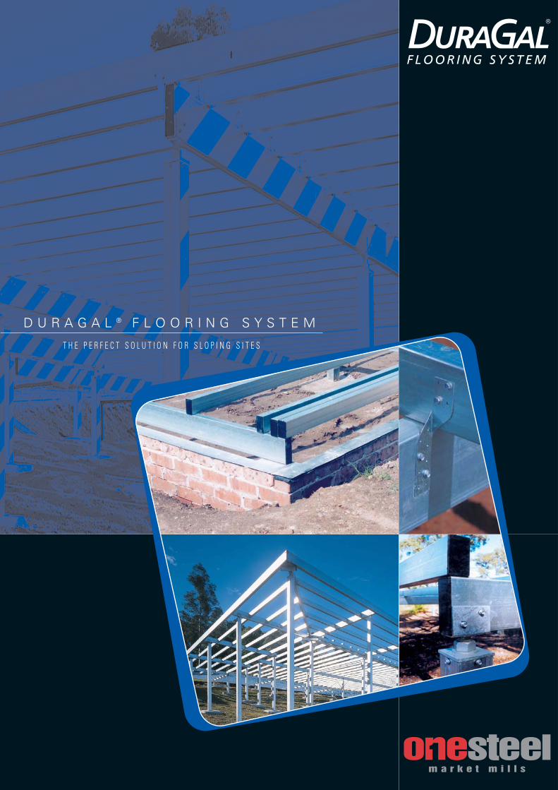
D U R A G A L ® F L O O R I N G S Y S T E M
T H E P E R F E C T S O L U T I O N F O R S L O P I N G S I T E S

august 02 DuraGal® Flooring System Page 2
Letter ofCertification
Monday, 12 August 2002
OneSteel Market MillsPO Box 156NEWCASTLE NSW 2300
Dear Sir,
RE: Structural Engineers CertificationDuraGal Flooring Tables
We hereby certify that we have checked the structural aspects of the design tables1 to 28 in the DuraGal Flooring System Brochure dated August 2002.
The tables and accompanying information must be strictly followed, or structuraladequacy or statutory compliance may be compromised.
We certify that members designed using these tables are structurally adequateand in accordance with the Building Code of Australia and relevant SAA Codes ofPractice.
Yours Faithfully,MORGAN CONSULTING ENGINEERS PTY LTD
Robert N Morgan CPEng
MORGAN CONSULTING
ENGINEERS PTY LTDABN 82 009 859 081
1 GREAT GEORGE STREETPADDINGTON QLD 4064
◆ STRUCTURAL ◆ CIVIL ◆ HOUSING ◆ FORENSIC ◆
For further information please contact OneSteel Direct Telephone: 1800 1 STEEL (1800 1 78335) Facsimile: 1800 101 141
Email: [email protected] brochure contains general information about the use of the DuraGal Flooring System in single storey residential buildings. This information is a guide onlyand not a substitute for expert advice on how to successfully design and construct a residential building or install a flooring system. Successful design,construction and installation depends on many factors beyond the scope of this brochure, including, for example, correct site preparation, proper care of productprior to installation, workmanship during installation and engineering judgments specific to each installation. Product specification and other information in this brochure may change at any time without further notice. OneSteel does not accept any responsibility for otherproducts named in, for any error in, or omission from, this brochure or for any loss or damage or other consequence arising from the use of this brochure by anyperson.

Difficult or sloping site construction can beeasily handled by the DuraGal FlooringSystem. Developed by OneSteel MarketMills, the DuraGal Flooring System is a steelflooring system utilising the higher strengthand lighter weight advantages of DuraGalHollow sections. The DuraGal FlooringSystem is suitable for a wide range of singlestorey residential homes, decks andcommercial floors.
The DuraGal Flooring System has beendeveloped by OneSteel to provide a simple,strong and lightweight modular system tohandle difficult or sloping site construction.The system utilises the higher strength andlighter weight advantages of DuraGalhollow sections to produce a floor systemthat’s suitable for a wide range of buildingapplications.
FeaturesUser friendly – Requires only normal tradeand electrical tools, no welding is involved.
Fast and accurate levelling of the floorduring or after construction is a greatfeature, and compensates for variations inthe footings, now or later.
Surface Protection – Internally paintedDuraGal hollow sections have an In-line hotdip, galvanized coating with a minimumaverage coating mass of 100g/m2 applied tothe external surface, the internal surface iscoated with a 35 micron thick ZincPhosphate coating. Recommended for usein non-aggressive environments*.
Quality – OneSteel’s commitment to qualitymeans you can depend on DuraGal productsto deliver reliable & consistent quality tosite.
Versatility – New span tables for live loadsof 1.5kPa, 3.0kPa and 5.0kPa, means theDuraGal Flooring System is now moreversatile than ever.
The many benefits offered by the DuraGalFlooring System has seen it adopted bymany leading housing constructioncompanies as their preferred system forsloping sites.
Suitable for single storey residential homes,decks and commercial floors, it offers theflexibility and ease of installation that cansubstantially reduce your on siteconstruction costs.
Why you should use theDuraGal® Flooring System: - ● Simple and straightforward installation. ● No welding required.● Unaffected by termites. ● DuraGal won’t shrink, rot or warp like
timber, helping to reduce expensive callbacks.
● Larger spans, which can open up under-floor areas for use as workshop or storage.
● Improved underfloor access and ventilation. (less piers)
● The costs of site preparation such as, cut and fill, retaining walls and drainage can be minimised.
● Has the advantage of higher strength, lightweight, and corrosion resistant* DuraGal hollow steel sections.
● Manufactured to tight tolerances.● Longer lengths.● Comprehensive range of standard fittings
to suit most applications.● Floor sheets can still fixed by traditional
methods.● Australian made and available nationally
* Refer to pages 22 to 29 of this publication for moredetails on corrosive environments & appropriateprecautions during installation of exposed floorsmembers.
Joist Spans
DuraGal®
Flooring System
august 02 DuraGal® Flooring System Page 3
Coating System
In-line Hot-dipGalvanized Coating
CleanedSurface
InternallyPainted
The DuraGal Flooring System is yetanother example of the innovativebuilding solutions developed byOneSteel Market Mills.
Isn’t it time you started building abetter floor with the DuraGalFlooring System?
Selection of materialsIn the construction of a floor system,building products manufactured byOneSteel Market Mills, and buildingproducts manufactured by othercompanies will be used. The productinformation in this publication relatessolely to the products manufactured byOneSteel Market Mills.
It is strongly recommended that onlyDuraGal Internally painted hollowsections manufactured by OneSteel bespecified for use when using the designinformation in this publication. Testingusing only OneSteel Products hasvalidated the design criteria containedwithin this publication. It isrecommended a note to this effect isincluded on any design documentation.
SurfaceConversionCoating
Now you can build a better floor with the DuraGal Flooring System

What the Users SayMr. Bruce LouisProduction & Design Manager, AV Jennings Homes, Wyong NSW.
‘With fluctuating timber prices and instability of supply, we looked for an
alternative system to the traditional timber bearers and joists for construction
of elevated floors on sloping sites. After trialing several systems we adopted
the DuraGal® Flooring System as our preferred option as it offers the best and
most cost effective solution for our company.”
“An added benefit provided by this system is that it offers extra useable space
under the floor which is used as a real selling feature.”
Mr. Dennis McColl
Managing Director, Aus Steel, Beresfield, NSW.
“It enables you to keep the floor nice and straight. We have also used the
system a lot in patios, especially where there is no underfloor lining. It is a
good, neat section that finishes off well.”
Mr. Jason Watts
Production Manager, Executive Homes, Country Victoria and Southern NSW.
“The DuraGal® Flooring System provides us with a flexible building system well
suited to a wide range of home designs and site conditions. The major benefits
to us include, being galvanized steel, being resistant to termite attack, easy to
install, and providing a strong low maintenance system. Whenever an elevated
floor is required we would recommend the DuraGal® Flooring System to our
clients.”
DuraGal®
Letter of Certification ........................ 2
Features & Benefits ..........................3
What Users Say ........................ 4
Joist Spans For 1.5 kPa Floors ........................ 5
Bearer Spans For 1.5 kPa Floors ........................ 6
Joist Spans For 3 & 5 kPa Floors..................... 7
Bearer Spans For 3 & 5 kPa Floors....................... 8
Cantilever Spans For 1.5 kPa Floors....................... 9
Cantilever Spans For 3 kPa Floors................... 10
Cantilever Spans For 5 kPa Floors.................... 11
Assembly - Brick Veneer....................... 12
Assembly - Free Standing ...................... 13
Bracing Details ...................... 15
Connections - Capacities ...................... 16
Footing Details ...................... 17
Construction Hints ...................... 18
Accessories ...................... 19
Termite Barriers ...................... 21
Corrosion Guide ...................... 22
Sealing of Fittings ........................24
Nailing ...................... 30
Cutting ...................... 30
Flooring System
Contents
august 02 DuraGal® Flooring System Page 4
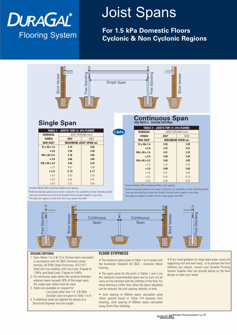
75 x 50 x 1.6 2.14 2.05x 2.0 2.30 2.20
100 x 50 x1.6 2.78 2.65x 2.0 3.00 2.85
150 x 50 x 2.0 4.44 4.16x 2.5 4.81 4.49
x 3.0 5.13 4.77x 4.0 5.52 5.20
x 5.0 5.65 5.41
x 6.0 5.73 5.50
TABLE 1 – JOISTS FOR 1.5 kPa FLOORSDURAGAL JOIST SPACING (mm)
C450L0 4501 600RHS SIZE2 MAXIMUM JOIST SPAN (m)
Single SpanContinuous Span
DESIGN CRITERIA1. Span Tables 1 to 4 & 13 to 16 have been calculated
in accordance with AS 3623: Domestic metal framing, AS 4100: Steel Structures, AS1170.1: Dead and Live Loading, with Live Load, Q equal to 1.5kPa, and Dead Load, G equal to 0.4kPa.
2. For continuous span where the variation between adjacent spans exceeds 30% of the larger span, the single span tables must be used.
3. Tables are available on request for:- Live loads other than 1.5, 3 & 5kPa- DuraGal sizes not given in Table 1 to 6
4. If additional loads are applied the advice of aStructural Engineer must be sought.
FLOOR STIFFNESS
• The maximum spans given in Table 1 to 4 comply withthe Australian Standard AS 3623 - Domestic MetalFraming.
• The spans given for the joists in Tables 1 and 2 arethe maximum recommended spans and as such not allusers will be satisfied with the stiffness of the floor. Forthose desiring a stiffer floor either the spans tabulatedcan be reduced, the joist spacing reduced, or both.
• Joist spacing of 450mm spans calculated using19mm particle board or 15mm F14 plywood floorsheeting. Joist spacing of 600mm spans calculatedusing 22mm floor sheeting.
75 x 50x 1.6 2.52 2.39x 2.0 2.72 2.57
100 x 50 x 1.6 3.31 3.10x 2.0 3.59 3.34
150 x 50 x 2.0 5.46 4.95x 2.5 5.74 5.34
x 3.0 5.98 5.56x 4.0 6.31 5.88
x 5.0 6.45 6.14
x 6.0 6.55 6.28
TABLE 2 – JOISTS FOR 1.5 kPa FLOORSDURAGAL JOIST SPACING (mm)
C450L0 4501 600RHS SIZE2 MAXIMUM SPAN (m)
(SEE NOTE 2 - DESIGN CRITERIA)
Joist SpansFor 1.5 kPa Domestic Floors
Cyclonic & Non Cyclonic RegionsFlooring System
1 OneSteel Market Mills recommend 450mm joist spacing.2 Preferred internally painted sizes shown in bold print. For availability of other internally painted
sizes we recommend you consult the DuraGal Flooring System supplier in your area.3 This table also applies to decks with floor areas greater than 40m2
august 02 DuraGal® Flooring System Page 5
1.5kPa
• If you need guidance for large open areas, areas notsupporting roof and wall loads, or to achieve the floorstiffness you require, consult your DuraGal FlooringSystem Supplier who can provide advice on the floordesign to meet your needs.
Single Span
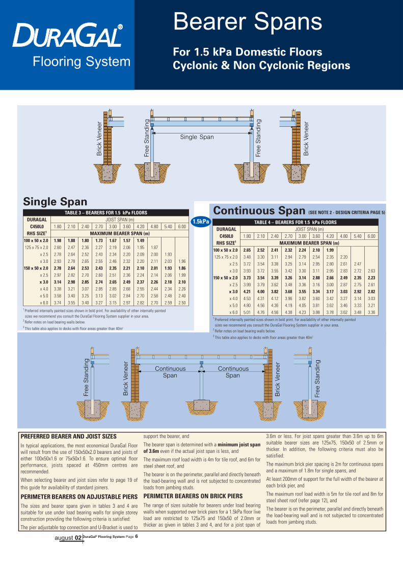
PREFERRED BEARER AND JOIST SIZESIn typical applications, the most economical DuraGal Floorwill result from the use of 150x50x2.0 bearers and joists ofeither 100x50x1.6 or 75x50x1.6. To ensure optimal floorperformance, joists spaced at 450mm centres arerecommended.
When selecting bearer and joist sizes refer to page 19 ofthis guide for availability of standard joiners.
PERIMETER BEARERS ON ADJUSTABLE PIERSThe sizes and bearer spans given in tables 3 and 4 aresuitable for use under load bearing walls for single storeyconstruction providing the following criteria is satisfied:
The pier adjustable top connection and U-Bracket is used to
support the bearer, and
The bearer span is determined with a minimum joist spanof 3.6m even if the actual joist span is less, and
The maximum roof load width is 4m for tile roof, and 6m forsteel sheet roof, and
The bearer is on the perimeter, parallel and directly beneaththe load-bearing wall and is not subjected to concentratedloads from jambing studs.
PERIMETER BEARERS ON BRICK PIERSThe range of sizes suitable for bearers under load bearingwalls when supported over brick piers for a 1.5kPa floor liveload are restricted to 125x75 and 150x50 of 2.0mm orthicker as given in tables 3 and 4, and for a joist span of
3.6m or less. For joist spans greater than 3.6m up to 6msuitable bearer sizes are 125x75, 150x50 of 2.5mm orthicker. In addition, the following criteria must also besatisfied:
The maximum brick pier spacing is 2m for continuous spansand a maximum of 1.8m for single spans, and
At least 200mm of support for the full width of the bearer ateach brick pier, and
The maximum roof load width is 5m for tile roof and 8m forsteel sheet roof (refer page 12), and
The bearer is on the perimeter, parallel and directly beneaththe load-bearing wall and is not subjected to concentratedloads from jambing studs.
100 x 50 x 2.0 1.98 1.88 1.80 1.73 1.67 1.57 1.49125 x 75 x 2.0 2.60 2.47 2.36 2.27 2.19 2.06 1.95 1.87
x 2.5 2.78 2.64 2.52 2.43 2.34 2.20 2.09 2.00 1.93
x 3.0 2.93 2.78 2.65 2.55 2.46 2.32 2.20 2.11 2.03 1.96
150 x 50 x 2.0 2.78 2.64 2.53 2.43 2.35 2.21 2.10 2.01 1.93 1.86x 2.5 2.97 2.82 2.70 2.60 2.51 2.36 2.24 2.14 2.06 1.99
x 3.0 3.14 2.98 2.85 2.74 2.65 2.49 2.37 2.26 2.18 2.10x 4.0 3.38 3.21 3.07 2.95 2.85 2.68 2.55 2.44 2.34 2.26
x 5.0 3.58 3.40 3.25 3.13 3.02 2.84 2.70 2.58 2.48 2.40
x 6.0 3.74 3.55 3.40 3.27 3.15 2.97 2.82 2.70 2.59 2.50
TABLE 3 – BEARERS FOR 1.5 kPa FLOORSDURAGAL JOIST SPAN (m)
C450L0 1.80 2.10 2.40 2.70 3.00 3.60 4.20 4.80 5.40 6.00RHS SIZE1 MAXIMUM BEARER SPAN (m)
100 x 50 x 2.0 2.65 2.52 2.41 2.32 2.24 2.10 1.99125 x 75 x 2.0 3.48 3.30 3.11 2.94 2.79 2.54 2.35 2.20
x 2.5 3.72 3.54 3.38 3.25 3.14 2.95 2.80 2.61 2.47
x 3.0 3.93 3.72 3.55 3.42 3.30 3.11 2.95 2.83 2.72 2.63
150 x 50 x 2.0 3.73 3.54 3.39 3.26 3.14 2.88 2.66 2.49 2.35 2.23x 2.5 3.99 3.79 3.62 3.48 3.36 3.16 3.00 2.87 2.75 2.61
x 3.0 4.21 4.00 3.82 3.68 3.55 3.34 3.17 3.03 2.92 2.82x 4.0 4.53 4.31 4.12 3.96 3.82 3.60 3.42 3.27 3.14 3.03
x 5.0 4.80 4.56 4.36 4.19 4.05 3.81 3.62 3.46 3.33 3.21
x 6.0 5.01 4.76 4.56 4.38 4.23 3.98 3.78 3.62 3.48 3.36
TABLE 4 – BEARERS FOR 1.5 kPa FLOORSDURAGAL JOIST SPAN (m)
C450L0 1.80 2.10 2.40 2.70 3.00 3.60 4.20 4.80 5.40 6.00RHS SIZE1 MAXIMUM BEARER SPAN (m)
Continuous Span (SEE NOTE 2 - DESIGN CRITERIA PAGE 5)
Bearer Spans
Flooring SystemFor 1.5 kPa Domestic Floors
Cyclonic & Non Cyclonic Regions
1 Preferred internally painted sizes shown in bold print. For availability of other internally painted sizes we recommend you consult the DuraGal Flooring System supplier in your area.
2 Refer notes on load bearing walls below.3 This table also applies to decks with floor areas greater than 40m2
1 Preferred internally painted sizes shown in bold print. For availability of other internally painted sizes we recommend you consult the DuraGal Flooring System supplier in your area.
2 Refer notes on load bearing walls below.3 This table also applies to decks with floor areas greater than 40m2
august 02 DuraGal® Flooring System Page 6
1.5kPa

75 x 50 x 1.6 2.14 2.05x 2.0 2.30 2.20
100 x 50 x1.6 2.78 2.65x 2.0 3.00 2.85
150 x 50 x 2.0 4.29 3.99x 2.5 4.51 4.20
x 3.0 4.69 4.37x 4.0 4.96 4.62
x 5.0 5.18 4.82
x 6.0 5.36 4.98
TABLE 5 – JOISTS FOR 3 kPa FLOORSDURAGAL JOIST SPACING (mm)
C450L0 4501 600RHS SIZE2 MAXIMUM JOIST SPAN (m)
Joist SpansFor 3kPa & 5 kPa Commercial Floors
Cyclonic & Non Cyclonic Regions
Single Span Continuous Span
Flooring System
75 x 50x 1.6 2.52 2.39x 2.0 2.72 2.55
100 x 50 x 1.6 3.24 2.71x 2.0 3.54 3.22
150 x 50 x 2.0 4.59 3.83x 2.5 4.83 4.49
x 3.0 5.03 4.68x 4.0 5.32 4.95
x 5.0 5.55 5.17
x 6.0 5.73 5.34
TABLE 6 – JOISTS FOR 3 kPa FLOORSDURAGAL JOIST SPACING (mm)
C450L0 4501 600RHS SIZE2 MAXIMUM SPAN (m)
1 OneSteel Market Mills recommend 450mm joist spacing.2 Preferred internally painted sizes shown in bold print. For availability of other internally painted
sizes we recommend you consult the DuraGal Flooring System supplier in your area.3 This table also applies to decks with floor areas less than 40m2
1 OneSteel Market Mills recommend 450mm joist spacing.2 Preferred internally painted sizes shown in bold print. For availability of other internally
painted sizes we recommend you consult the DuraGal Flooring System supplier in your area.
1 OneSteel Market Mills recommend 450mm joist spacing.2 Preferred internally painted sizes shown in bold print. For availability of other internally
painted sizes we recommend you consult the DuraGal Flooring System supplier in your area.
(SEE NOTE 2 - DESIGN CRITERIA)
75 x 50 x 1.6 2.02 1.84x 2.0 2.16 1.96
100 x 50 x1.6 2.55 2.32x 2.0 2.73 2.48
150 x 50 x 2.0 3.77 3.48x 2.5 3.97 3.69
x 3.0 4.13 3.84x 4.0 4.37 4.07
x 5.0 4.56 4.25
x 6.0 4.71 4.39
TABLE 7 – JOISTS FOR 5 kPa FLOORSDURAGAL JOIST SPACING (mm)
C450L0 4501 600RHS SIZE2 MAXIMUM JOIST SPAN (m)
Single Span Continuous Span
75 x 50x 1.6 2.21 1.87x 2.0 2.37 2.15
100 x 50 x 1.6 2.37 1.96x 2.0 2.99 2.70
150 x 50 x 2.0 3.31 2.69x 2.5 4.25 3.83
x 3.0 4.42 4.12x 4.0 4.68 4.35
x 5.0 4.88 4.55
x 6.0 5.05 4.70
TABLE 8 – JOISTS FOR 5 kPa FLOORSDURAGAL JOIST SPACING (mm)
C450L0 4501 600RHS SIZE2 MAXIMUM SPAN (m)
(SEE NOTE 2 - DESIGN CRITERIA)
DESIGN CRITERIA1. Span Tables 5 to 12 & 17 to 24 have been calculated
in accordance with AS 3623: Domestic metal framing, AS 4100: Steel Structures, AS1170.1: Dead and Live Loading, with 3kPa Tables,Live Load Q=3kPa,Dead Load G=0.657kPa 5kPa Tables,Live Load Q=5kPa, Dead Load G=1.0kPa
2. For continuous span where the variation between adjacent spans exceeds 30% of the larger span, the single span tables must be used.
3. Tables are available on request for:- Live loads other than 1.5, 3 & 5kPa- DuraGal sizes not given in Table 1 to 12
4. If additional loads are applied the advice of aStructural Engineer must be sought.
FLOOR STIFFNESS
• The maximum spans given in Table 1 to 4 comply withthe Australian Standard AS 3623 - Domestic MetalFraming.
• The spans given for the joists in Tables 5 to 8 are themaximum recommended spans and as such not all userswill be satisfied with the stiffness of the floor. For thosedesiring a stiffer floor either the spans tabulated can bereduced, the joist spacing reduced, or both.
• Joist spacing of 450mm spans calculated using 19mmparticle board or 15mm F14 plywood floor sheeting. Joistspacing of 600mm spans calculated using 22mm floorsheeting.
august 02 DuraGal® Flooring System Page 7
3kPa
5kPa
• If you need guidance for large open areas, areas notsupporting roof and wall loads, or to achieve the floorstiffness you require, consult your DuraGal FlooringSystem Supplier who can provide advice on the floordesign to meet your needs.

Bearer Spans
Flooring SystemFor 3kPa & 5 kPa Commercial Floors
Cyclonic & Non Cyclonic Regions
Single Span
100 x 50 x 2.0 1.57 1.49 1.43 1.37 1.33 1.25 1.18 1.13 1.09 1.05125 x 75 x 2.0 2.06 1.95 1.87 1.80 1.74 1.63 1.55 1.48 1.43 1.38
x 2.5 2.20 2.09 2.00 1.92 1.86 1.75 1.66 1.59 1.53 1.47
x 3.0 2.32 2.21 2.11 2.03 1.96 1.84 1.75 1.68 1.61 1.56
150 x 50 x 2.0 2.21 2.10 2.00 1.93 1.86 1.75 1.66 1.59 1.53 1.48x 2.5 2.36 2.24 2.14 2.06 1.99 1.87 1.78 1.70 1.64 1.58
x 3.0 2.49 2.37 2.26 2.18 2.10 1.98 1.88 1.80 1.73 1.67x 4.0 2.68 2.55 2.44 2.34 2.26 2.13 2.02 1.94 1.86 1.80
x 5.0 2.84 2.70 2.58 2.48 2.40 2.26 2.14 2.05 1.97 1.90
x 6.0 2.97 2.82 2.70 2.59 2.50 2.36 2.24 2.14 2.06 1.99
TABLE 9 – BEARERS FOR 3 kPa FLOORSDURAGAL JOIST SPAN (m)
C450L0 1.80 2.10 2.40 2.70 3.00 3.60 4.20 4.80 5.40 6.00RHS SIZE1 MAXIMUM BEARER SPAN2 (m)
100 x 50 x 2.0 2.11 2.00 1.91 1.81 1.72 1.57 1.45 1.36 1.28 1.22125 x 75 x 2.0 2.59 2.40 2.24 2.12 2.01 1.83 1.70 1.59 1.50 1.42
x 2.5 2.95 2.81 2.65 2.50 2.37 2.17 2.01 1.88 1.77 1.68
x 3.0 3.12 2.96 2.83 2.72 2.63 2.47 2.32 2.17 2.05 1.94
150 x 50 x 2.0 2.93 2.71 2.53 2.39 2.27 2.07 1.92 1.79 1.69 1.60x 2.5 3.16 3.01 2.87 2.76 2.66 2.43 2.25 2.10 1.98 1.88
x 3.0 3.34 3.17 3.03 2.92 2.82 2.64 2.44 2.28 2.15 2.04x 4.0 3.60 3.42 3.27 3.14 3.03 2.86 2.71 2.58 2.43 2.30
x 5.0 3.81 3.62 3.46 3.33 3.21 3.03 2.87 2.75 2.64 2.53
x 6.0 3.98 3.78 3.62 3.48 3.36 3.16 3.00 2.87 2.76 2.67
TABLE 10 – BEARERS FOR 3 kPa FLOORSDURAGAL JOIST SPAN (m)
C450L0 1.80 2.10 2.40 2.70 3.00 3.60 4.20 4.80 5.40 6.00RHS SIZE1 MAXIMUM BEARER SPAN2 (m)
Continuous Span(SEE NOTE 2 - DESIGN CRITERIA PAGE 7)
Single Span
100 x 50 x 2.0 1.60 1.52 1.45 1.39 1.34 1.22 1.13 1.06 1.00125 x 75 x 2.0 2.02 1.87 1.75 1.65 1.57 1.43 1.32 1.24 1.17 1.11
x 2.5 2.24 2.12 2.03 1.95 1.85 1.69 1.57 1.46 1.38 1.25
x 3.0 2.36 2.24 2.14 2.06 1.99 1.87 1.78 1.69 1.60 1.52
150 x 50 x 2.0 2.24 2.11 1.98 1.86 1.77 1.61 1.49 1.33 1.18 1.06x 2.5 2.40 2.28 2.18 2.09 2.02 1.89 1.75 1.64 1.55 1.47
x 3.0 2.53 2.40 2.30 2.21 2.13 2.01 1.90 1.78 1.68 1.59x 4.0 2.73 2.59 2.48 2.38 2.30 2.16 2.05 1.97 1.89 1.80
x 5.0 2.89 2.74 2.62 2.52 2.43 2.29 2.18 2.08 2.00 1.93
x 6.0 3.02 2.86 2.74 2.63 2.54 2.39 2.27 2.17 2.09 2.02
TABLE 11 – BEARERS FOR 5 kPa FLOORSDURAGAL JOIST SPAN (m)
C450L0 1.80 2.10 2.40 2.70 3.00 3.60 4.20 4.80 5.40 6.00RHS SIZE1 MAXIMUM BEARER SPAN2 (m)
100 x 50 x 2.0 1.73 1.60 1.50 1.41 1.34 1.22 1.13 1.06 1.00125 x 75 x 2.0 2.02 1.87 1.75 1.65 1.57 1.43 1.32 1.24 1.17 1.11
x 2.5 2.39 2.21 2.07 1.95 1.85 1.69 1.57 1.46 1.38 1.31
x 3.0 2.59 2.46 2.35 2.26 2.14 1.96 1.81 1.69 1.60 1.52
150 x 50 x 2.0 2.28 2.11 1.98 1.86 1.77 1.61 1.49 1.40 1.32 1.19x 2.5 2.63 2.48 2.32 2.19 2.07 1.89 1.75 1.64 1.55 1.47
x 3.0 2.77 2.63 2.52 2.38 2.25 2.06 1.90 1.78 1.68 1.59x 4.0 2.99 2.84 2.71 2.61 2.52 2.32 2.15 2.01 1.89 1.80
x 5.0 3.16 3.00 2.87 2.76 2.67 2.51 2.36 2.21 2.08 1.97
x 6.0 3.30 3.14 3.00 2.89 2.79 2.62 2.49 2.37 2.24 2.12
TABLE 12 – BEARERS FOR 5 kPa FLOORSDURAGAL JOIST SPAN (m)
C450L0 1.80 2.10 2.40 2.70 3.00 3.60 4.20 4.80 5.40 6.00RHS SIZE1 MAXIMUM BEARER SPAN2 (m)
Continuous Span(SEE NOTE 2 - DESIGN CRITERIA PAGE 7)
1 Preferred internally painted sizes shown in bold print. For availability of other internally painted sizes we recommend you consult the DuraGal Flooring System supplier in your area.
2 Refer notes on load bearing walls below3 This table also applies to decks with floor areas less than 40m2
1 Preferred internally painted sizes shown in bold print. For availability of other internally painted sizes we recommend you consult the DuraGal Flooring System supplier in your area.
2 Refer notes on load bearing walls below
1 Preferred internally painted sizes shown in bold print. For availability of other internally painted sizes we recommend you consult the DuraGal Flooring System supplier in your area.
2 Refer notes on load bearing walls below3 This table also applies to decks with floor areas less than 40m2
1 Preferred internally painted sizes shown in bold print. For availability of other internally painted sizes we recommend you consult the DuraGal Flooring System supplier in your area.
2 Refer notes on load bearing walls below
PREFERRED BEARER AND JOIST SIZESWhen selecting bearer and joist sizes refer to page 19 ofthis guide for availability of standard joiners.
PERIMETER BEARERS ON ADJUSTABLE PIERSThe sizes and bearer spans given in tables 9 to 12 aresuitable for use under load bearing walls for singlestorey construction providing the following criteria issatisfied:
- The pier adjustable top connection and U-Bracket isused to support the bearer, and
- The bearer span is determined with a minimum joist
span of 3.6m even if the actual joist span is less, and
- The maximum roof load width is 4m for tile roof, and 6mfor steel sheet roof, and
- The bearer is on the perimeter, parallel and directlybeneath the load-bearing wall and is not subjected toconcentrated loads from jambing studs.
PERIMETER BEARERS ON BRICK PIERSThe range of sizes suitable for bearers under load
bearing walls when supported over brick piers for a1.5kPa floor live load are restricted to 125x75 & 150x50of 2.5mm or thicker as given in tables 9 to 12, and for ajoist span of 3.6m or less. For joist spans greater than
3.6m up to 6m suitable bearer sizes are 150x50 of 4.0mmor thicker. In addition, the following criteria must also besatisfied:
- The maximum brick pier spacing is 2m for continuousspans and a maximum of 1.8m for single spans, and
- At least 200mm of support for the full width of thebearer at each brick pier, and
- The maximum roof load width is 5m for tile roof and 8mfor steel sheet roof (refer page 12), and
- The bearer is on the perimeter, parallel and directlybeneath the load-bearing wall and is not subjected toconcentrated loads from jambing studs.
august 02 DuraGal® Flooring System Page 8
3kPa
5kPa

Cantilever SpansFor 1.5 kPa Domestic Floors
Cyclonic & Non Cyclonic RegionsFlooring System
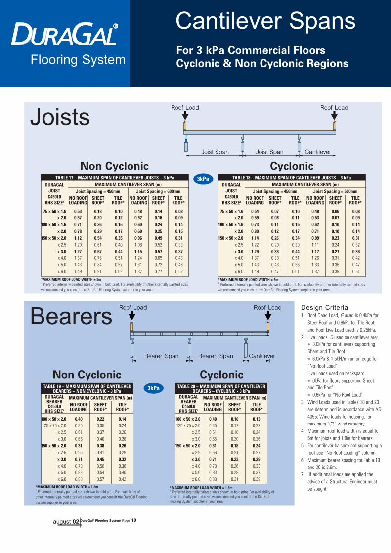
75 x 50 x 1.6 0.53 0.18 0.10 0.47 0.15 0.08x 2.0 0.58 0.20 0.12 0.51 0.17 0.09
100 x 50 x 1.6 0.74 0.27 0.16 0.65 0.22 0.13x 2.0 0.81 0.30 0.18 0.72 0.25 0.14
150 x 50 x 2.0 1.29 0.52 0.31 1.14 0.44 0.26x 2.5 1.39 0.59 0.36 1.25 0.49 0.29x 3.0 1.45 0.65 0.40 1.33 0.55 0.33x 4.0 1.55 0.75 0.47 1.43 0.63 0.38x 5.0 1.62 0.85 0.54 1.50 0.70 0.43x 6.0 1.67 0.93 0.59 1.55 0.76 0.48
TABLE 13 – MAXIMUM SPAN OF CANTILEVER JOISTS – 1.5 kPaMAXIMUM CANTILEVER SPAN (m)
Joist Spacing = 450mm Joist Spacing = 600mmNO ROOF SHEET TILE NO ROOF SHEET TILELOADING ROOF* ROOF* LOADING ROOF* ROOF*
DURAGALJOISTC450L0
RHS SIZE1
100 x 50 x 2.0 0.44 0.21 0.12125 x 75 x 2.0 0.50 0.32 0.20
x 2.5 0.70 0.36 0.23x 3.0 0.75 0.40 0.25
150 x 50 x 2.0 0.48 0.36 0.23x 2.5 0.77 0.40 0.26x 3.0 0.82 0.44 0.29x 4.0 0.91 0.50 0.33x 5.0 0.96 0.54 0.36x 6.0 1.01 0.58 0.39
TABLE 15 – MAXIMUM SPAN OF CANTILEVERBEARERS – NON CYCLONIC - 1.5 kPa
MAXIMUM CANTILEVER SPAN (m)NO ROOF SHEET TILELOADING ROOF* ROOF*
DURAGALBEARERC450L0
RHS SIZE1
Non Cyclonic
Non Cyclonic
Cyclonic
Cyclonic
Design Criteria1. Roof Dead Load, G used is 0.4kPa for
Steel Roof and 0.9kPa for Tile Roof, andRoof Live Load used is 0.25kPa.
2. Live Loads, Q used on cantilever are:∗ 1.5kPa for cantilevers supportingSheet and Tile Roof∗ 3.0kPa & 1.5kN/m run on edge for “No Roof Load”Live Loads used on backspan:∗ 0kPa for floors supporting Sheet andTile Roof∗ 0.3kPa for “No Roof Load”
3. Wind Loads used in Tables 14 and 16are determined in accordance with AS4055: Wind loads for housing, formaximum “C3” wind category.
4. Maximum roof load width is equal to5m for joists and 1.8m for bearers.
5. For cantilever balcony not supporting aroof use “No Roof Loading” column.
6. Maximum bearer spacing for Table 15and 16 is 3.6m.
7. If additional loads are applied theadvice of a Structural Engineer must besought.
Joists
Bearers
*MAXIMUM ROOF LOAD WIDTH = 5m1 Preferred internally painted sizes shown in bold print. For availability of other internally
painted sizes we recommend you consult the DuraGal Flooring System supplier in your area.
*MAXIMUM ROOF LOAD WIDTH = 1.8m1 Preferred internally painted sizes shown in bold print. For availability of otherinternally painted sizes we recommend you consult the DuraGal FlooringSystem supplier in your area.
100 x 50 x 2.0 0.44 0.08 0.11125 x 75 x 2.0 0.50 0.14 0.18
x 2.5 0.70 0.15 0.21x 3.0 0.75 0.17 0.23
150 x 50 x 2.0 0.48 0.15 0.21x 2.5 0.77 0.18 0.24x 3.0 0.82 0.19 0.26x 4.0 0.91 0.22 0.30x 5.0 0.96 0.25 0.33x 6.0 1.01 0.27 0.36
TABLE 16 – MAXIMUM SPAN OF CANTILEVERBEARERS – CYCLONIC - 1.5 kPa
MAXIMUM CANTILEVER SPAN (m)NO ROOF SHEET TILELOADING ROOF* ROOF*
DURAGALBEARERC450L0
RHS SIZE1
*MAXIMUM ROOF LOAD WIDTH = 1.8m1 Preferred internally painted sizes shown in bold print. For availability ofother internally painted sizes we recommend you consult the DuraGal FlooringSystem supplier in your area.
75 x 50 x 1.6 0.53 0.07 0.09 0.47 0.05 0.07x 2.0 0.58 0.07 0.10 0.51 0.06 0.08
100 x 50 x 1.6 0.74 0.10 0.14 0.65 0.08 0.11x 2.0 0.81 0.11 0.16 0.72 0.09 0.13
150 x 50 x 2.0 1.29 0.20 0.28 1.14 0.17 0.23x 2.5 1.39 0.24 0.32 1.25 0.19 0.26x 3.0 1.45 0.26 0.36 1.33 0.22 0.29x 4.0 1.55 0.31 0.42 1.43 0.25 0.34x 5.0 1.62 0.36 0.48 1.50 0.29 0.39x 6.0 1.67 0.40 0.53 1.55 0.32 0.43
TABLE 14 – MAXIMUM SPAN OF CANTILEVER JOISTS – 1.5 kPaMAXIMUM CANTILEVER SPAN (m)
Joist Spacing = 450mm Joist Spacing = 600mmNO ROOF SHEET TILE NO ROOF SHEET TILELOADING ROOF* ROOF* LOADING ROOF* ROOF*
DURAGALJOISTC450L0
RHS SIZE1
*MAXIMUM ROOF LOAD WIDTH = 5m1 Preferred internally painted sizes shown in bold print. For availability of other internally
painted sizes we recommend you consult the DuraGal Flooring System supplier in your area.
august 02 DuraGal® Flooring System Page 9
1.5kPa
1.5kPa
Cantilever SpansFor 3 kPa Commercial Floors
Cyclonic & Non Cyclonic RegionsFlooring System
75 x 50 x 1.6 0.53 0.18 0.10 0.48 0.14 0.08x 2.0 0.57 0.20 0.12 0.52 0.16 0.09
100 x 50 x 1.6 0.71 0.26 0.16 0.60 0.24 0.14x 2.0 0.78 0.29 0.17 0.69 0.25 0.15
150 x 50 x 2.0 1.12 0.54 0.35 0.96 0.49 0.31x 2.5 1.20 0.61 0.40 1.08 0.52 0.33x 3.0 1.27 0.67 0.44 1.15 0.57 0.37x 4.0 1.37 0.76 0.51 1.24 0.65 0.43x 5.0 1.43 0.84 0.57 1.31 0.72 0.48x 6.0 1.49 0.91 0.62 1.37 0.77 0.52
TABLE 17 – MAXIMUM SPAN OF CANTILEVER JOISTS – 3 kPaMAXIMUM CANTILEVER SPAN (m)
Joist Spacing = 450mm Joist Spacing = 600mmNO ROOF SHEET TILE NO ROOF SHEET TILELOADING ROOF* ROOF* LOADING ROOF* ROOF*
DURAGALJOISTC450L0
RHS SIZE1
100 x 50 x 2.0 0.40 0.22 0.14125 x 75 x 2.0 0.35 0.35 0.24
x 2.5 0.61 0.37 0.26x 3.0 0.65 0.40 0.28
150 x 50 x 2.0 0.31 0.38 0.26x 2.5 0.56 0.41 0.29x 3.0 0.71 0.45 0.32x 4.0 0.78 0.50 0.36x 5.0 0.83 0.54 0.40x 6.0 0.88 0.57 0.42
TABLE 19 – MAXIMUM SPAN OF CANTILEVERBEARERS – NON CYCLONIC - 3 kPa
MAXIMUM CANTILEVER SPAN (m)NO ROOF SHEET TILELOADING ROOF* ROOF*
DURAGALBEARERC450L0
RHS SIZE1
Non Cyclonic
Non Cyclonic
Cyclonic
Cyclonic
Design Criteria1. Roof Dead Load, G used is 0.4kPa for
Steel Roof and 0.9kPa for Tile Roof,and Roof Live Load used is 0.25kPa.
2. Live Loads, Q used on cantilever are:∗ 3.0kPa for cantilevers supportingSheet and Tile Roof∗ 6.0kPa & 1.5kN/m run on edge for“No Roof Load”Live Loads used on backspan:∗ 0kPa for floors supporting Sheetand Tile Roof∗ 0.6kPa for “No Roof Load”
3. Wind Loads used in Tables 18 and 20are determined in accordance with AS4055: Wind loads for housing, formaximum “C3” wind category.
4. Maximum roof load width is equal to5m for joists and 1.8m for bearers.
5. For cantilever balcony not supporting aroof use “No Roof Loading” column.
6. Maximum bearer spacing for Table 19and 20 is 3.6m.
7. If additional loads are applied theadvice of a Structural Engineer mustbe sought.
Joists
Bearers
*MAXIMUM ROOF LOAD WIDTH = 5m1 Preferred internally painted sizes shown in bold print. For availability of other internally painted sizeswe recommend you consult the DuraGal Flooring System supplier in your area.
*MAXIMUM ROOF LOAD WIDTH = 1.8m1 Preferred internally painted sizes shown in bold print. For availability ofother internally painted sizes we recommend you consult the DuraGal FlooringSystem supplier in your area.
100 x 50 x 2.0 0.40 0.10 0.13125 x 75 x 2.0 0.35 0.17 0.22
x 2.5 0.61 0.18 0.24x 3.0 0.65 0.20 0.26
150 x 50 x 2.0 0.31 0.18 0.24x 2.5 0.56 0.21 0.27x 3.0 0.71 0.23 0.29x 4.0 0.78 0.26 0.33x 5.0 0.83 0.29 0.37x 6.0 0.88 0.31 0.39
TABLE 20 – MAXIMUM SPAN OF CANTILEVERBEARERS – CYCLONIC - 3 kPa
MAXIMUM CANTILEVER SPAN (m)NO ROOF SHEET TILELOADING ROOF* ROOF*
DURAGALBEARERC450L0
RHS SIZE1
*MAXIMUM ROOF LOAD WIDTH = 1.8m1 Preferred internally painted sizes shown in bold print. For availability ofother internally painted sizes we recommend you consult the DuraGalFlooring System supplier in your area.
75 x 50 x 1.6 0.54 0.07 0.10 0.49 0.06 0.08x 2.0 0.59 0.08 0.11 0.53 0.07 0.09
100 x 50 x 1.6 0.73 0.11 0.15 0.62 0.10 0.14x 2.0 0.80 0.12 0.17 0.71 0.10 0.14
150 x 50 x 2.0 1.14 0.26 0.34 0.99 0.23 0.31x 2.5 1.22 0.29 0.39 1.11 0.24 0.32x 3.0 1.29 0.33 0.44 1.17 0.27 0.36x 4.0 1.37 0.38 0.51 1.26 0.31 0.42x 5.0 1.43 0.43 0.56 1.33 0.35 0.47x 6.0 1.49 0.47 0.61 1.37 0.39 0.51
TABLE 18 – MAXIMUM SPAN OF CANTILEVER JOISTS – 3 kPaMAXIMUM CANTILEVER SPAN (m)
Joist Spacing = 450mm Joist Spacing = 600mmNO ROOF SHEET TILE NO ROOF SHEET TILELOADING ROOF* ROOF* LOADING ROOF* ROOF*
DURAGALJOISTC450L0
RHS SIZE1
*MAXIMUM ROOF LOAD WIDTH = 5m1 Preferred internally painted sizes shown in bold print. For availability of other internally painted sizeswe recommend you consult the DuraGal Flooring System supplier in your area.
august 02 DuraGal® Flooring System Page 10
3kPa
3kPa
Cantilever SpansFor 5 kPa Commercial Floors
Cyclonic & Non Cyclonic RegionsFlooring System
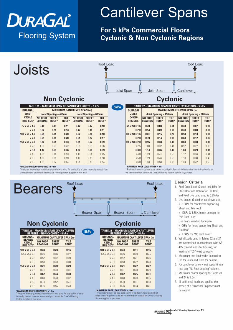
75 x 50 x 1.6 0.48 0.19 0.11 0.42 0.17 0.10x 2.0 0.52 0.21 0.13 0.47 0.18 0.11
100 x 50 x 1.6 0.59 0.31 0.20 0.52 0.28 0.18x 2.0 0.69 0.31 0.20 0.61 0.27 0.17
150 x 50 x 2.0 0.92 0.61 0.43 0.81 0.57 0.39x 2.5 1.06 0.60 0.42 0.95 0.53 0.36x 3.0 1.12 0.66 0.46 1.02 0.56 0.39x 4.0 1.21 0.74 0.53 1.10 0.64 0.45x 5.0 1.28 0.81 0.59 1.16 0.70 0.50x 6.0 1.33 0.87 0.64 1.21 0.75 0.54
TABLE 21 – MAXIMUM SPAN OF CANTILEVER JOISTS – 5 kPaMAXIMUM CANTILEVER SPAN (m)
Joist Spacing = 450mm Joist Spacing = 600mmNO ROOF SHEET TILE NO ROOF SHEET TILELOADING ROOF* ROOF* LOADING ROOF* ROOF*
DURAGALJOISTC450L0
RHS SIZE1
100 x 50 x 2.0 0.34 0.23 0.16125 x 75 x 2.0 0.26 0.36 0.27
x 2.5 0.52 0.37 0.28x 3.0 0.58 0.40 0.30
150 x 50 x 2.0 0.21 0.39 0.29x 2.5 0.41 0.40 0.31x 3.0 0.62 0.44 0.33x 4.0 0.68 0.48 0.37x 5.0 0.73 0.52 0.41x 6.0 0.76 0.55 0.43
TABLE 23 – MAXIMUM SPAN OF CANTILEVERBEARERS – NON CYCLONIC - 5 kPa
MAXIMUM CANTILEVER SPAN (m)NO ROOF SHEET TILELOADING ROOF* ROOF*
DURAGALBEARERC450L0
RHS SIZE1
Non Cyclonic
Non Cyclonic
Cyclonic
Cyclonic
Design Criteria1. Roof Dead Load, G used is 0.4kPa for
Steel Roof and 0.9kPa for Tile Roof,and Roof Live Load used is 0.25kPa.
2. Live Loads, Q used on cantilever are:∗ 5.0kPa for cantilevers supportingSheet and Tile Roof∗ 10kPa & 1.5kN/m run on edge for“No Roof Load”Live Loads used on backspan:∗ 0kPa for floors supporting Sheet andTile Roof∗ 1.0kPa for “No Roof Load”
3. Wind Loads used in Tables 22 and 24are determined in accordance with AS4055: Wind loads for housing, formaximum “C3” wind category.
4. Maximum roof load width is equal to5m for joists and 1.8m for bearers.
5. For cantilever balcony not supporting aroof use “No Roof Loading” column.
6. Maximum bearer spacing for Table 23and 24 is 3.6m.
7. If additional loads are applied theadvice of a Structural Engineer mustbe sought.
Joists
Bearers
*MAXIMUM ROOF LOAD WIDTH = 5m1 Preferred internally painted sizes shown in bold print. For availability of other internally painted sizeswe recommend you consult the DuraGal Flooring System supplier in your area.
*MAXIMUM ROOF LOAD WIDTH = 1.8m1 Preferred internally painted sizes shown in bold print. For availability of otherinternally painted sizes we recommend you consult the DuraGal FlooringSystem supplier in your area.
100 x 50 x 2.0 0.34 0.11 0.15125 x 75 x 2.0 0.26 0.20 0.25
x 2.5 0.52 0.21 0.26x 3.0 0.58 0.22 0.28
150 x 50 x 2.0 0.21 0.22 0.27x 2.5 0.41 0.23 0.29x 3.0 0.62 0.25 0.31x 4.0 0.68 0.28 0.35x 5.0 0.73 0.31 0.38x 6.0 0.76 0.34 0.41
TABLE 24 – MAXIMUM SPAN OF CANTILEVERBEARERS – CYCLONIC - 5 kPa
MAXIMUM CANTILEVER SPAN (m)NO ROOF SHEET TILELOADING ROOF* ROOF*
DURAGALBEARERC450L0
RHS SIZE1
*MAXIMUM ROOF LOAD WIDTH = 1.8m1 Preferred internally painted sizes shown in bold print. For availability ofother internally painted sizes we recommend you consult the DuraGal FlooringSystem supplier in your area.
75 x 50 x 1.6 0.49 0.08 0.11 0.43 0.07 0.10x 2.0 0.54 0.09 0.12 0.48 0.08 0.10
100 x 50 x 1.6 0.61 0.15 0.20 0.53 0.13 0.18x 2.0 0.70 0.14 0.19 0.63 0.12 0.16
150 x 50 x 2.0 0.95 0.33 0.42 0.84 0.30 0.39x 2.5 1.08 0.32 0.41 0.97 0.27 0.35x 3.0 1.14 0.36 0.46 1.04 0.29 0.38x 4.0 1.23 0.41 0.53 1.12 0.34 0.44x 5.0 1.29 0.46 0.59 1.19 0.38 0.49x 6.0 1.34 0.50 0.63 1.24 0.42 0.53
TABLE 22 – MAXIMUM SPAN OF CANTILEVER JOISTS – 5 kPaMAXIMUM CANTILEVER SPAN (m)
Joist Spacing = 450mm Joist Spacing = 600mmNO ROOF SHEET TILE NO ROOF SHEET TILELOADING ROOF* ROOF* LOADING ROOF* ROOF*
DURAGALJOISTC450L0
RHS SIZE1
*MAXIMUM ROOF LOAD WIDTH = 5m1 Preferred internally painted sizes shown in bold print. For availability of other internally painted sizeswe recommend you consult the DuraGal Flooring System supplier in your area.
august 02 DuraGal® Flooring System Page 11
5kPa
5kPa
Brick VeneerNon Cyclonic Regions
Example of fixing for High Wind
Examples of Load Bearing Wallssupported by Bearers
AssemblyFlooring System
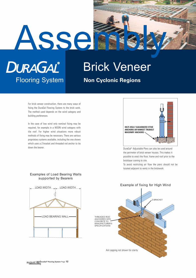
DuraGal® Adjustable Piers can also be used aroundthe perimeter of brick veneer houses. This makes itpossible to erect the floor, frame and roof prior to the bricklayer coming to site.To avoid restricting air flow the piers should not belocated adjacent to vents in the brickwork.
Ant capping not shown for clarity
HILTI-HSA-F GALVANIZED STUDANCHORS OR RAMSET TRUBOLTMASONRY ANCHORS
For brick veneer construction, there are many ways offixing the DuraGal Flooring System to the brick work.The method used depends on the wind category andbuilding preferences.
In the case of low wind only nominal fixing may berequired, for example in a W33N wind category withtile roof. For higher wind situations more robustmethods of fixing may be necessary. There are variousproprietary systems available, including the one shownwhich uses a Z-bracket and threaded rod anchor to tiedown the bearer.
august 02 DuraGal® Flooring System Page 12

Assembly
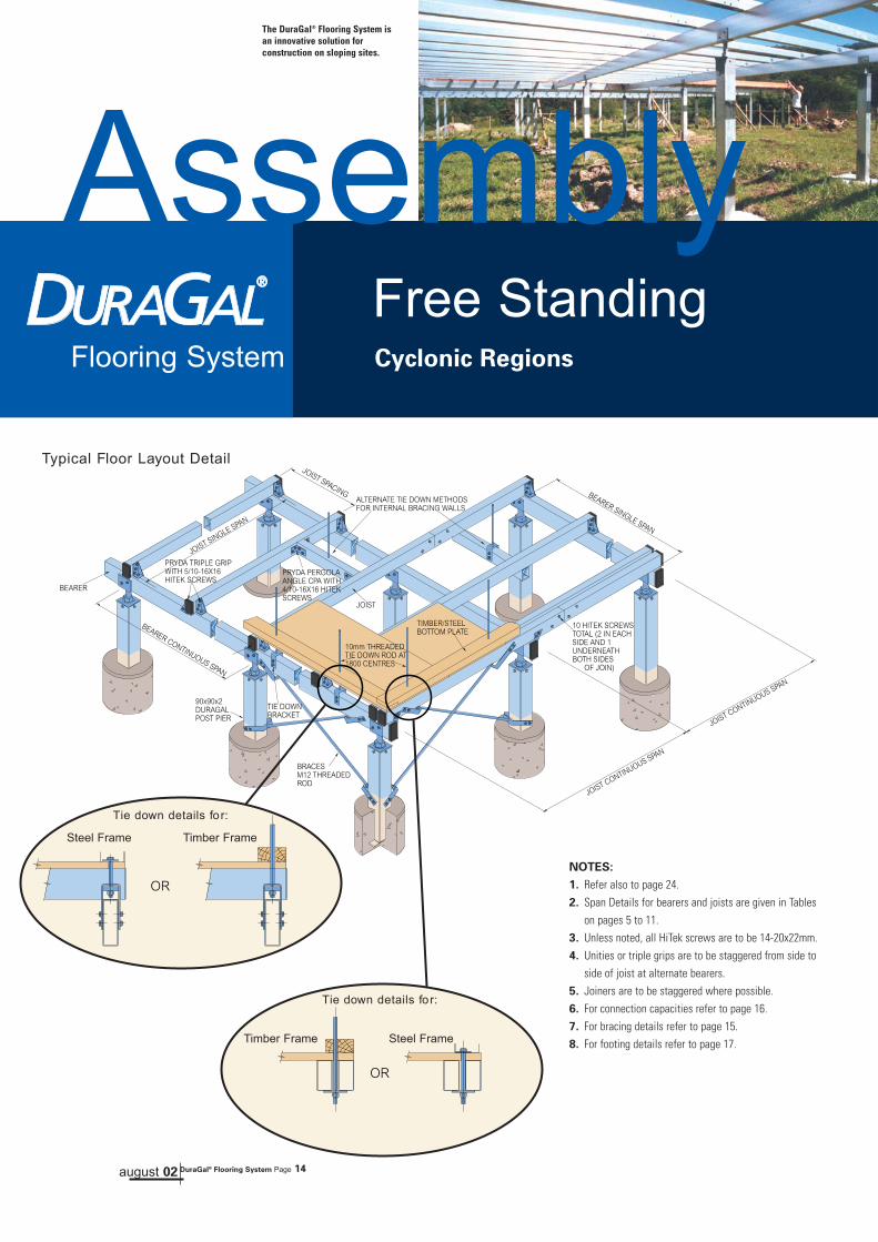
Typical Floor Layout Detail
The DuraGal® Flooring System is aninnovative solution for construction onsloping sites.
Free StandingNon Cyclonic Regions
NOTES:
1. Refer also to page 24.2. Span Details for bearers and joists are given in Tables
on pages 5 to 11.3. Unless noted, all HiTek screws are to be 14-20x22mm.4. Unities, triple grips or pergola angles are to be
staggered from side to side of joist at alternate bearers.5. Joiners are to be staggered where possible.6. For connection capacities refer to page 16.7. For bracing details refer to page 15.8. For footing details refer to page 17.
Max 100mmRecommend < 70mm
Maximum extension of pier adjustable top connection
BARRIER PAINT
august 02 DuraGal® Flooring System Page 13
Flooring System
Assembly
Typical Floor Layout Detail
The DuraGal® Flooring System isan innovative solution forconstruction on sloping sites.
Flooring System
Free StandingCyclonic Regions
NOTES:
1. Refer also to page 24.2. Span Details for bearers and joists are given in Tables
on pages 5 to 11.3. Unless noted, all HiTek screws are to be 14-20x22mm.4. Unities or triple grips are to be staggered from side to
side of joist at alternate bearers.5. Joiners are to be staggered where possible.6. For connection capacities refer to page 16.7. For bracing details refer to page 15.8. For footing details refer to page 17.
Tie down details for:
Steel Frame Timber Frame
Tie down details for:
Steel FrameTimber Frame
august 02 DuraGal® Flooring System Page 14

BracingCapacities
Wind pressure produces horizontal loads on DuraGal FlooringSystem. For free standing floors these loads are transferred tothe footings through the use of sub-floor bracing.
Galvanized cross bracing sets are available from your DuraGalFlooring Supplier. Each bracing set is made up of brackets,washers, M12 threaded rods and four nuts. The details of theseitems are shown on page 20. The bracing brackets are attachedwith 14-20x22 Tek screws c/w sealing washers, see Detail 8page 28.
When installed, the bracing is attached to the bottom of the pierand then to either the bearer or joist, depending on the directionbeing braced, as shown in the diagrams on this page. Table 25gives horizontal load capacities for a single bracing set wheninstalled at various angles.
As differing wind load conditions apply throughout Australia,engineering certification is required for both the number ofbracing sets required and where they are to be installed.
Advice must be sought from a professional structuralengineer in regard to the location and number of bracingsets to be used.
HorizontalForce, FH
100mmMAX
Bracing from pier to Joist
100mmMAX
35º to 60º
HorizontalForce, FH
Bracing from pier to Bearer
35 13.0 8.69
40 12.2 8.13
45 11.3 7.50
50 10.2 6.82
55 9.13 6.08
60 7.95 5.30
TABLE 25 – BRACING CAPACITIESBRACING MAX. HORIZONTAL FORCE, FH (kN)
ANGLE ULTIMATE PERMISSIBLE(degrees) DESIGN STRESS DESIGN
august 02 DuraGal® Flooring System Page 15
Flooring System

AXIAL AXIALCONSTRUCTION
COMPRESSION TENSIONTOP FITTING
4/14-20x22 Tek Screws 70 25
8/14-20x22 Tek Screws 70 35
BOTTOM FITTING4/14-20x22 Tek Screws / 2xM10 Anchors 25
8/14-20x22 Tek Screws / 2xM12 Anchors 35
TABLE 28 –DURAGAL PIER & FITTING CAPACITY (kN)
FOR HEIGHTS UP TO 4.5m
NOTES:
- All loads are strength limit state design capacities.- When fittings are used in exposed areas the proceduresshown on pages 24-29 should be followed.
ConnectionsCapacities
TABLE 26 – FLOOR JOIST TIE DOWN CAPACITY (kN)
PRYDA PERGOLA ANGLE
minimum 1/10-16x16 tek 0*
screw in each leg
*joist lifts off before connection engages
PRYDA UNITIE
4/10-16x16 tek screws 3.86
2 in each face
PRYDA TRIPLE GRIP
6/10-16x16 tek screws 3.53
2 in each face
TABLE 27 – TIE DOWN CAPACITY* (kN)
U-BRACKET 50mm - WITH M12 ROD
4/14-20x20 tek screws 11.25
2 per leg
*typically to tie down rafter/trusses tofloor frame
august 02 DuraGal® Flooring System Page 16
ConnectionsFlooring System
Capacities

NOTES:
Guidance for engineers only
Pad Footing Sizes from AS2870for Class A, S and M sites.
1. Footings to be designed to AS 2870: Residential slabs and footings. Depth of footing Df from AS 2870
2. The effective area supported by a pad footing is the sum of: (a) the supported floor area; (b) the supported roof area (if applicable); and (c ) half the supported wallarea in elevation (if applicable).
3. Pad footings should be finished 50mm above ground level as shown by “A”.
4. Where backfilling is required (shown by “B”) the concrete for the pad needs to be raised 50mm above the finish ground line.
5. Where piers are embedded into the pads as shown by “C” it is required to apply a barrier coating to a minimum of 100mm above expected final concrete height. Thepier bottom connection is also to be painted all round as specified above.Suggested Coatings: Wattyl DuraGal Supaprime (Chlorinated Rubber based). Preparation and application to paint manufacturer’s specification .
Footing parameters will differ with varying soil conditionsand wind loadings. Local building approval authoritieshave differing requirements for the size and depth offootings. It is important that anyone designing andconstructing a building seek expert advice from astructural engineer on the requirements specific to eachbuilding.
The following information on footings is a general guideonly and not a substitute for expert advice.
Typical Footing Detail
Brick veneer
Free Standing
EFFECTIVE WIDTH OF DIAMETER THICKNESS SUPPORTED SQUARE PAD OF CIRCULAR (MIN)
AREA, m2 mm PAD, mm mm
10 400 500 200
20 500 600 200
40 600 750 250
”C” See note 5
”C” See note 5
Masonry Anchor
DuraGal PierTop Face Trowlled To 1 in 30Away From Post
30 1
Width or Diameter toEngineers Specification
100mm min (may bePrecast)
50mm min
Dept
h to
Eng
inee
rsSp
ecifi
catio
n
august 02 DuraGal® Flooring System Page 17
ConnectionsCapacities
FootingsFlooring System
Details
No site welding necessary
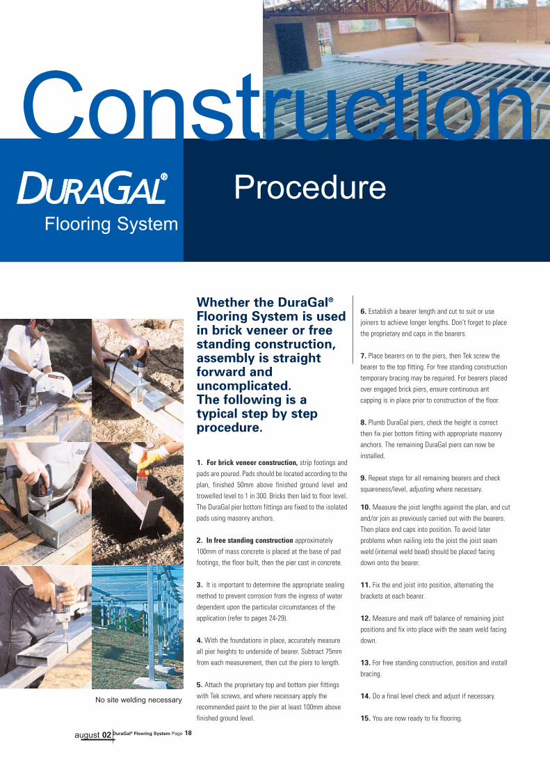
Whether the DuraGal®
Flooring System is usedin brick veneer or freestanding construction,assembly is straightforward anduncomplicated. The following is atypical step by stepprocedure.
1. For brick veneer construction, strip footings andpads are poured. Pads should be located according to theplan, finished 50mm above finished ground level andtrowelled level to 1 in 300. Bricks then laid to floor level.The DuraGal pier bottom fittings are fixed to the isolatedpads using masonry anchors.
2. In free standing construction approximately100mm of mass concrete is placed at the base of padfootings, the floor built, then the pier cast in concrete.
3. It is important to determine the appropriate sealingmethod to prevent corrosion from the ingress of waterdependent upon the particular circumstances of theapplication (refer to pages 24-29).
4. With the foundations in place, accurately measureall pier heights to underside of bearer. Subtract 75mmfrom each measurement, then cut the piers to length.
5. Attach the proprietary top and bottom pier fittingswith Tek screws, and where necessary apply therecommended paint to the pier at least 100mm abovefinished ground level.
6. Establish a bearer length and cut to suit or usejoiners to achieve longer lengths. Don’t forget to placethe proprietary end caps in the bearers.
7. Place bearers on to the piers, then Tek screw thebearer to the top fitting. For free standing constructiontemporary bracing may be required. For bearers placedover engaged brick piers, ensure continuous antcapping is in place prior to construction of the floor.
8. Plumb DuraGal piers, check the height is correctthen fix pier bottom fitting with appropriate masonryanchors. The remaining DuraGal piers can now beinstalled.
9. Repeat steps for all remaining bearers and checksquareness/level, adjusting where necessary.
10. Measure the joist lengths against the plan, and cutand/or join as previously carried out with the bearers.Then place end caps into position. To avoid laterproblems when nailing into the joist the joist seamweld (internal weld bead) should be placed facingdown onto the bearer.
11. Fix the end joist into position, alternating thebrackets at each bearer.
12. Measure and mark off balance of remaining joistpositions and fix into place with the seam weld facingdown.
13. For free standing construction, position and installbracing.
14. Do a final level check and adjust if necessary.
15. You are now ready to fix flooring.
of the DuraGal® Flooring System
august 02 DuraGal® Flooring System Page 18
ConstructionFlooring System
Procedure
STRAIGHT - Galvabond
75x50x1.6/2.0 JI-755020
100x50x1.6/2.0 JI-1005020
150x50x2.0 JI-1505020
150x50x3.0 JI-1505030
90° ANGLE - Galvabond
75x50x1.6/2.0 JI-90-755020
100x50x1.6/2.0 JI-90-1005020
150x50x2.0 JI-90-1505020
45° ANGLE - Galvabond
75x50x1.6 JI-45-755020
100x50x2.0 JI-45-1005020
150x50x2.0 JI-45-1505020
JOINERS RHS SIZE CODE
100 Min.
50 Min.
DEPTH TO �ENGINEERS �SPECIFICATIONS
100 Min.
WIDTH OR DIAMETER TO �ENGINEERS SPECIFICATIONS
50 Min.
PRYDA TRIPLE WITH�5/10-16x16 HITEK SCREWS��
JOINER INSIDE
10 HITEK SCREWS�TOTAL (2 IN EACH�SIDE AND I�UNDERNEATH �BOTH SIDES �OF JOIN)
"C" SEE NOTE �PAGE 9
CONTINUOUS SPAN
CONTINUOUS SPAN
PRYDA UNITIE WITH�2/10-16x16 HITEK SCREWS�UPLIFT CAPACITY - 6.8kN
PRYDA PERGOLA�ANGLE CPA WITH�2/10-16x16 HITEK �SCREWS��
JOISTBEARER
VERMIN PROOF� END CAPS
CLORINATED �RUBBER PAINT
SIMPLE SPAN
100 Min.
50 Min.
DEPTH TO �ENGINEERS �SPECIFICATIONS
100 Min.
WIDTH OR DIAMETER TO �ENGINEERS SPECIFICATIONS
50 Min.
PRYDA TRIPLE WITH�5/10-16x16 HITEK SCREWS��
JOINER INSIDE
10 HITEK SCREWS�TOTAL (2 IN EACH�SIDE AND I�UNDERNEATH �BOTH SIDES �OF JOIN)
"C" SEE NOTE �PAGE 9
CONTINUOUS SPAN
CONTINUOUS SPAN
PRYDA UNITIE WITH�2/10-16x16 HITEK SCREWS�UPLIFT CAPACITY - 6.8kN
PRYDA PERGOLA�ANGLE CPA WITH�2/10-16x16 HITEK �SCREWS��
JOISTBEARER
VERMIN PROOF� END CAPS
CLORINATED �RUBBER PAINT
SIMPLE SPAN
END CAP - Polypropylene
75x50x1.6/2.0 PC7550
100x50x1.6/2.0 PC10050
150x50x2.0 PC15050
PIER BOTTOM CONNECTION
90x90x2.0 SBC-90
MISCELLANEOUS RHS SIZE CODE
100 Min.
50 Min.
DEPTH TO �ENGINEERS �SPECIFICATIONS
100 Min.
WIDTH OR DIAMETER TO �ENGINEERS SPECIFICATIONS
50 Min.
PRYDA TRIPLE WITH�5/10-16x16 HITEK SCREWS��
JOINER INSIDE
10 HITEK SCREWS�TOTAL (2 IN EACH�SIDE AND I�UNDERNEATH �BOTH SIDES �OF JOIN)
"C" SEE NOTE �PAGE 9
CONTINUOUS SPAN
CONTINUOUS SPAN
PRYDA UNITIE WITH�2/10-16x16 HITEK SCREWS�UPLIFT CAPACITY - 6.8kN
PRYDA PERGOLA�ANGLE CPA WITH�2/10-16x16 HITEK �SCREWS��
JOISTBEARER
VERMIN PROOF� END CAPS
CLORINATED �RUBBER PAINT
SIMPLE SPAN
100 Min.
50 Min.
DEPTH TO �ENGINEERS �SPECIFICATIONS
100 Min.
WIDTH OR DIAMETER TO �ENGINEERS SPECIFICATIONS
50 Min.
PRYDA TRIPLE WITH�5/10-16x16 HITEK SCREWS��
JOINER INSIDE
10 HITEK SCREWS�TOTAL (2 IN EACH�SIDE AND I�UNDERNEATH �BOTH SIDES �OF JOIN)
"C" SEE NOTE �PAGE 9
CONTINUOUS SPAN
CONTINUOUS SPAN
PRYDA UNITIE WITH�2/10-16x16 HITEK SCREWS�UPLIFT CAPACITY - 6.8kN
PRYDA PERGOLA�ANGLE CPA WITH�2/10-16x16 HITEK �SCREWS��
JOISTBEARER
VERMIN PROOF� END CAPS
CLORINATED �RUBBER PAINT
SIMPLE SPAN
PIER ADJUSTABLE TOP CONNECTION
90x90x2.0 SATC-90-50
PIER MULTI TOP ADJUSTABLE CONNECTION*
90x90x2.0 SATC-90-MT
*minimum order quantities may apply
PIER UNI TOP ADJUSTABLE CONNECTION*
90x90x2.0 SATC-90-FP3
*minimum order quantities may apply
ADJUSTABLE CONNECTERS RHS SIZE CODE
100 Min.
50 Min.
DEPTH TO �ENGINEERS �SPECIFICATIONS
100 Min.
WIDTH OR DIAMETER TO �ENGINEERS SPECIFICATIONS
50 Min.
PRYDA TRIPLE WITH�5/10-16x16 HITEK SCREWS��
JOINER INSIDE
10 HITEK SCREWS�TOTAL (2 IN EACH�SIDE AND I�UNDERNEATH �BOTH SIDES �OF JOIN)
"C" SEE NOTE �PAGE 9
CONTINUOUS SPAN
CONTINUOUS SPAN
PRYDA UNITIE WITH�2/10-16x16 HITEK SCREWS�UPLIFT CAPACITY - 6.8kN
PRYDA PERGOLA�ANGLE CPA WITH�2/10-16x16 HITEK �SCREWS��
JOISTBEARER
VERMIN PROOF� END CAPS
CLORINATED �RUBBER PAINT
SIMPLE SPAN
100 Min.
50 Min.
DEPTH TO �ENGINEERS �SPECIFICATIONS
100 Min.
WIDTH OR DIAMETER TO �ENGINEERS SPECIFICATIONS
50 Min.
PRYDA TRIPLE WITH�5/10-16x16 HITEK SCREWS��
JOINER INSIDE
10 HITEK SCREWS�TOTAL (2 IN EACH�SIDE AND I�UNDERNEATH �BOTH SIDES �OF JOIN)
"C" SEE NOTE �PAGE 9
CONTINUOUS SPAN
CONTINUOUS SPAN
PRYDA UNITIE WITH�2/10-16x16 HITEK SCREWS�UPLIFT CAPACITY - 6.8kN
PRYDA PERGOLA�ANGLE CPA WITH�2/10-16x16 HITEK �SCREWS��
JOISTBEARER
VERMIN PROOF� END CAPS
CLORINATED �RUBBER PAINT
SIMPLE SPAN
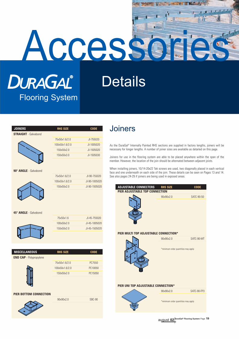
Joiners
As the DuraGal® Internally Painted RHS sections are supplied in factory lengths, joiners will benecessary for longer lengths. A number of joiner sizes are available as detailed on this page.
Joiners for use in the flooring system are able to be placed anywhere within the span of themember. However, the location of the join should be alternated between adjacent joists.
When installing joiners, 10/14-20x22 Tek screws are used, two diagonally placed in each verticalface and one underneath on each side of the join. These details can be seen on Pages 13 and 14.See also pages 24-29 if joiners are being used in exposed areas.
august 02 DuraGal® Flooring System Page 19
AccessoriesFlooring System
Details
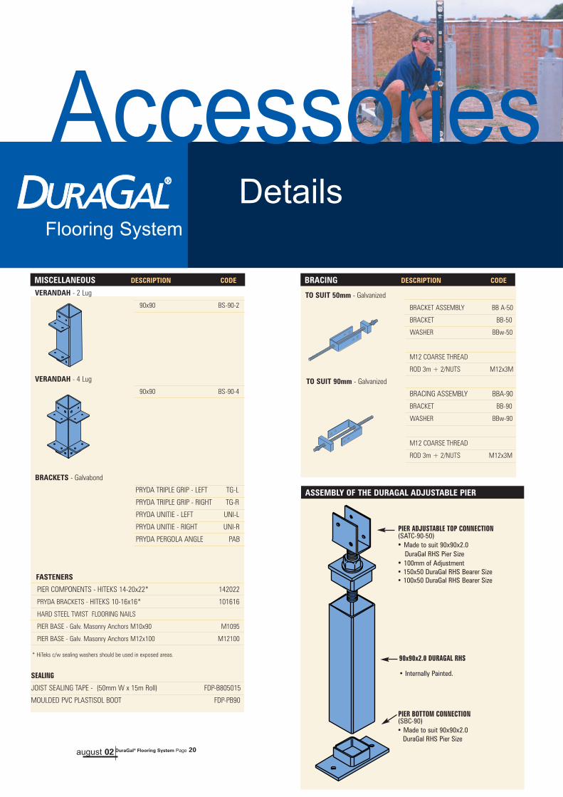
VERANDAH - 2 Lug
90x90 BS-90-2
VERANDAH - 4 Lug
90x90 BS-90-4
BRACKETS - Galvabond
PRYDA TRIPLE GRIP - LEFT TG-L
PRYDA TRIPLE GRIP - RIGHT TG-R
PRYDA UNITIE - LEFT UNI-L
PRYDA UNITIE - RIGHT UNI-R
PRYDA PERGOLA ANGLE PAB
FASTENERS
PIER COMPONENTS - HITEKS 14-20x22* 142022
PRYDA BRACKETS - HITEKS 10-16x16* 101616
HARD STEEL TWIST FLOORING NAILS
PIER BASE - Galv. Masonry Anchors M10x90 M1095
PIER BASE - Galv. Masonry Anchors M12x100 M12100
SEALING
JOIST SEALING TAPE - (50mm W x 15m Roll) FDP-B805015
MOULDED PVC PLASTISOL BOOT FDP-PB90
MISCELLANEOUS DESCRIPTION CODE
100 Min.
50 Min.
DEPTH TO �ENGINEERS �SPECIFICATIONS
100 Min.
WIDTH OR DIAMETER TO �ENGINEERS SPECIFICATIONS
50 Min.
PRYDA TRIPLE WITH�5/10-16x16 HITEK SCREWS��
JOINER INSIDE
10 HITEK SCREWS�TOTAL (2 IN EACH�SIDE AND I�UNDERNEATH �BOTH SIDES �OF JOIN)
"C" SEE NOTE �PAGE 9
CONTINUOUS SPAN
CONTINUOUS SPAN
PRYDA UNITIE WITH�2/10-16x16 HITEK SCREWS�UPLIFT CAPACITY - 6.8kN
PRYDA PERGOLA�ANGLE CPA WITH�2/10-16x16 HITEK �SCREWS��
JOISTBEARER
VERMIN PROOF� END CAPS
CLORINATED �RUBBER PAINT
SIMPLE SPAN
100 Min.
50 Min.
DEPTH TO �ENGINEERS �SPECIFICATIONS
100 Min.
WIDTH OR DIAMETER TO �ENGINEERS SPECIFICATIONS
50 Min.
PRYDA TRIPLE WITH�5/10-16x16 HITEK SCREWS��
JOINER INSIDE
10 HITEK SCREWS�TOTAL (2 IN EACH�SIDE AND I�UNDERNEATH �BOTH SIDES �OF JOIN)
"C" SEE NOTE �PAGE 9
CONTINUOUS SPAN
CONTINUOUS SPAN
PRYDA UNITIE WITH�2/10-16x16 HITEK SCREWS�UPLIFT CAPACITY - 6.8kN
PRYDA PERGOLA�ANGLE CPA WITH�2/10-16x16 HITEK �SCREWS��
JOISTBEARER
VERMIN PROOF� END CAPS
CLORINATED �RUBBER PAINT
SIMPLE SPAN
TO SUIT 50mm - Galvanized
BRACKET ASSEMBLY BB A-50
BRACKET BB-50
WASHER BBw-50
M12 COARSE THREAD
ROD 3m + 2/NUTS M12x3M
TO SUIT 90mm - Galvanized
BRACING ASSEMBLY BBA-90
BRACKET BB-90
WASHER BBw-90
M12 COARSE THREAD
ROD 3m + 2/NUTS M12x3M
BRACING DESCRIPTION CODE
ASSEMBLY OF THE DURAGAL ADJUSTABLE PIER
100 Min.
50 Min.
DEPTH TO �ENGINEERS �SPECIFICATIONS
100 Min.
WIDTH OR DIAMETER TO �ENGINEERS SPECIFICATIONS
50 Min.
PRYDA TRIPLE WITH�5/10-16x16 HITEK SCREWS��
JOINER INSIDE
10 HITEK SCREWS�TOTAL (2 IN EACH�SIDE AND I�UNDERNEATH �BOTH SIDES �OF JOIN)
"C" SEE NOTE �PAGE 9
CONTINUOUS SPAN
CONTINUOUS SPAN
PRYDA UNITIE WITH�2/10-16x16 HITEK SCREWS�UPLIFT CAPACITY - 6.8kN
PRYDA PERGOLA�ANGLE CPA WITH�2/10-16x16 HITEK �SCREWS��
JOISTBEARER
VERMIN PROOF� END CAPS
CLORINATED �RUBBER PAINT
SIMPLE SPAN
90x90x2.0 DURAGAL RHS
• Internally Painted.
PIER BOTTOM CONNECTION(SBC-90)• Made to suit 90x90x2.0
DuraGal RHS Pier Size
PIER ADJUSTABLE TOP CONNECTION (SATC-90-50)• Made to suit 90x90x2.0
DuraGal RHS Pier Size• 100mm of Adjustment• 150x50 DuraGal RHS Bearer Size• 100x50 DuraGal RHS Bearer Size
august 02 DuraGal® Flooring System Page 20
AccessoriesFlooring System
Details
* HiTeks c/w sealing washers should be used in exposed areas.

Flooring SystemRequires No Further
Termite Barriers
DuraGal®
No Further TermiteBarriers.
Australian Standard AS 3660.1: Protection of buildingsfrom subterranean termites, requires that “Termite shieldsshall be installed on all substructures (piers and walls)below the underside of the lowest floor framing memberto provide a continuous barrier for the protection of thebuilding” (Clause 4.2.1). “Termites can build aroundbarriers but they can then be detected more readily duringroutine inspection” (Note 1, Clause 1.1).
With masonry piers, this barrier is in the form of agalvanized sheet steel ant cap which, when placed on topof the masonry pier, forces the subterranean termites tobuild their tunnels around the steel and therefore can beseen in a visual inspection.
For tubular piers e.g. DuraGal piers, Clause 4.2.2 of AS3660.1 states that termite caps may be omitted wherewelded metal tubular piers are used, provided that thesepiers are free from perforations, sealed at the top andremain fully exposed for inspection.
With the DuraGal Flooring System, termites would haveto build a tunnel around the exposed solid steel threadedrod of the DuraGal pier adjustable top connection shownin the figure. This then offers a similar visual inspection
area to a traditional ant cap on a masonry pier and wouldbe deemed to comply.When using full continuous ant cap on brick dwarf walls,it is recommended that the same size bearer should beused throughout the DuraGal Flooring System to eliminatethe need to step the ant capping.
AS 3660.1 stresses that termites can bridge physicalbarrier systems and that regular and thorough inspectionsare necessary.
Flooring System
EXPOSED SOLIDSTEEL ROD
august 02 DuraGal® Flooring System Page 21
The Site Environment.
The metallurgical bond between the steel and the Zinc coating ofDuraGal generally imparts good corrosion resistance. However, thereare some environments where the rate of corrosion is so high that anysteel structure is at risk of rapid corrosion. The rate of corrosion isdependent upon environmental factors such as the amount ofcorrosive elements present and surface humidity. Sulphur compoundsfrom heavy industrial sites and chloride from marine environments aretwo commonly known corrosive elements. Acid and alkalineconditions will also accelerate the depletion of the zinc coatingleading to corrosion of the underlying steel.
While suitable for building applications in many environments foundthroughout Australia, the DuraGal Flooring System will not be suitablefor all environments. We do not recommend its use in applicationswhere there is a very high rate of corrosion, such as from marine orheavy industrial environments2.
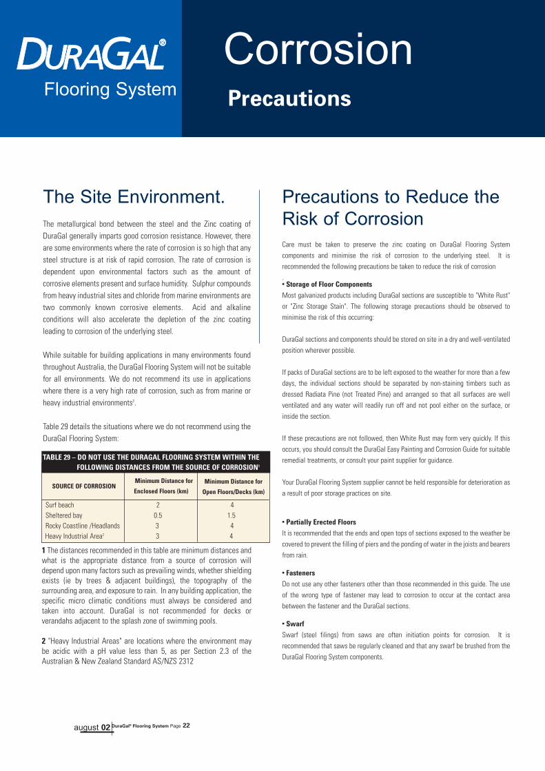
Table 29 details the situations where we do not recommend using theDuraGal Flooring System:
Flooring System
Surf beach 2 4Sheltered bay 0.5 1.5Rocky Coastline /Headlands 3 4Heavy Industrial Area2 3 4
SOURCE OF CORROSIONMinimum Distance for
Enclosed Floors (km)Minimum Distance for
Open Floors/Decks (km)
TABLE 29 – DO NOT USE THE DURAGAL FLOORING SYSTEM WITHIN THE FOLLOWING DISTANCES FROM THE SOURCE OF CORROSION1
1 The distances recommended in this table are minimum distances andwhat is the appropriate distance from a source of corrosion willdepend upon many factors such as prevailing winds, whether shieldingexists (ie by trees & adjacent buildings), the topography of thesurrounding area, and exposure to rain. In any building application, thespecific micro climatic conditions must always be considered andtaken into account. DuraGal is not recommended for decks orverandahs adjacent to the splash zone of swimming pools.
2 "Heavy Industrial Areas" are locations where the environment maybe acidic with a pH value less than 5, as per Section 2.3 of theAustralian & New Zealand Standard AS/NZS 2312
august 02 DuraGal® Flooring System Page 22
CorrosionPrecautions
Flooring System
Precautions to Reduce theRisk of CorrosionCare must be taken to preserve the zinc coating on DuraGal Flooring Systemcomponents and minimise the risk of corrosion to the underlying steel. It isrecommended the following precautions be taken to reduce the risk of corrosion.● Storage of Floor ComponentsMost galvanized products including DuraGal sections are susceptible to "White Rust"or "Zinc Storage Stain". The following storage precautions should be observed tominimise the risk of this occurring:
DuraGal sections and components should be stored on site in a dry and well-ventilatedposition wherever possible.
If packs of DuraGal sections are to be left exposed to the weather for more than a fewdays, the individual sections should be separated by non-staining timbers such asdressed Radiata Pine (not Treated Pine) and arranged so that all surfaces are wellventilated and any water will readily run off and not pool either on the surface, orinside the section.
If these precautions are not followed, then White Rust may form very quickly. If thisoccurs, you should consult the DuraGal Easy Painting and Corrosion Guide for suitableremedial treatments, or consult your paint supplier for guidance.
Your DuraGal Flooring System supplier cannot be held responsible for deterioration asa result of poor storage practices on site.
● Partially Erected FloorsIt is recommended that the ends and open tops of sections exposed to the weather becovered to prevent the filling of piers and the ponding of water in the joists and bearersfrom rain.
● FastenersDo not use any other fasteners other than those recommended in this guide. The useof the wrong type of fastener may lead to corrosion to occur at the contact areabetween the fastener and the DuraGal sections.
● SwarfSwarf (steel filings) from saws are often initiation points for corrosion. It isrecommended that saws be regularly cleaned and that any swarf be brushed from theDuraGal Flooring System components.
Flooring System
● Ponding of WaterThe ponding of water within DuraGal Flooring System sections must beavoided.Ponding of water may occur where the ends of sections have been incorrectlysealed, through top adjustable pier connections or by water ingress throughfastener holes. Decks and areas of open floor directly exposed to outdoorweather conditions are most susceptible to ponding.OneSteel have developed a number of techniques to reduce these risks. Pages24 to 29 address these risks in greater detail.
● Soil ContactContact between DuraGal flooring components and soil should be avoided byproper design of the footings because soil contact markedly increases thecorrosion rate of zinc. This is particularly true of clay soils. Please refer topage 17 for Footing Details.
● ConcreteAn appropriate paint system should be applied at least 100mm above andbelow the concrete junction where floor components are embedded inconcrete. Please refer to page 17 for Footing Details.
● Timber Contact (Exposed deck & verandahs)Do not use treated pine in direct contact with the DuraGal sections as this willincrease the corrosion rate of Zinc. Contact with some hardwood species willstain galvanized section. Although this staining is unsightly, it will notgenerally be detrimental to the performance of the product. The tape systemsrecommended in this brochure should be used as a barrier between all timberand DuraGal. Please refer to Detail 4 on page 26.
● Avoid Contact Between Dissimilar MetalsContact between dissimilar metal may increase the corrosion rate of one ofthem. In particular, the use of copper pipes on galvanized surfaces will bedetrimental to the galvanising. Water run off from one metal to another mayalso lead to corrosion of the galvanized metal.
● Painting FloorsUse the paint systems recommended in the "DuraGal Easy Painting andCorrosion Protection Guide" and the "DuraGal and Galtube Plus Powder CoatingGuide" as a general guide for how to paint floor components.For assistance, contact paint suppliers, or the paint manufacturers listed the"DuraGal Easy Painting and Corrosion Protection Guide" for advice on specificpaint systems to suit the climatic conditions of your site and application.Do not use solvent borne decking oils or paints because these solvents may bedetrimental to the barrier tapes recommended in this brochure.
● ChemicalsZinc corrosion is increased by acidic or alkaline conditions, and may occurwhere certain chemicals are present. A common example is the acid run off
which occurs from brick washing. Contact between these sorts of chemicalsand the DuraGal Flooring System components must be avoided. If accidentalcontact occurs, immediately hose down the contaminated area with water.If the galvanizing is affected, repair of the coating will be required to restorethe level of protection. Contact your DuraGal Flooring System supplier foradvice.
august 02 DuraGal® Flooring System Page 23
CorrosionPrecautions
Flooring System
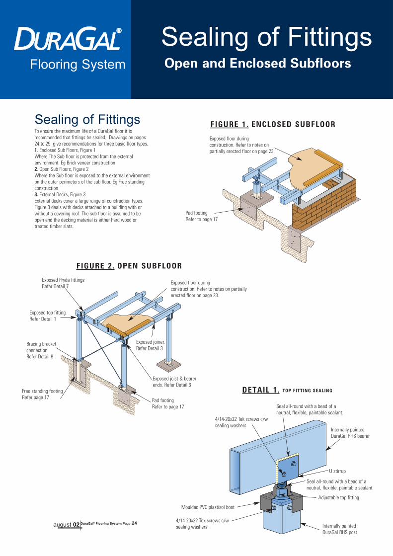
Sealing of FittingsTo ensure the maximum life of a DuraGal floor it isrecommended that fittings be sealed. Drawings on pages24 to 29 give recommendations for three basic floor types. 1. Enclosed Sub Floors, Figure 1Where The Sub floor is protected from the externalenvironment. Eg Brick veneer construction2. Open Sub Floors, Figure 2Where the Sub floor is exposed to the external environmenton the outer perimeters of the sub floor. Eg Free standingconstruction3. External Decks, Figure 3External decks cover a large range of construction types.Figure 3 deals with decks attached to a building with orwithout a covering roof. The sub floor is assumed to beopen and the decking material is either hard wood ortreated timber slats.
Pad footing Refer to page 17
Pad footing Refer to page 17
Bracing bracketconnectionRefer Detail 8
Free standing footing Refer page 17
Exposed joist & bearerends. Refer Detail 6
Exposed joiner.Refer Detail 3
Seal all-round with a bead of aneutral, flexible, paintable sealant.
Seal all-round with a bead of aneutral, flexible, paintable sealant.
4/14-20x22 Tek screws c/wsealing washers
Adjustable top fitting
U stirrup
4/14-20x22 Tek screws c/wsealing washers
Moulded PVC plastisol boot
Internally paintedDuraGal RHS bearer
Internally paintedDuraGal RHS post
Exposed top fittingRefer Detail 1
Exposed Pryda fittings Refer Detail 7
Exposed floor duringconstruction. Refer to notes onpartially erected floor on page 23.
Exposed floor duringconstruction. Refer to notes on partiallyerected floor on page 23.
FIGURE 1. ENCLOSED SUBFLOOR
FIGURE 2. OPEN SUBFLOOR
DETAIL 1. TOP FITTING SEALING
august 02 DuraGal® Flooring System Page 24
Sealing of FittingsOpen and Enclosed Subfloors

august 02 DuraGal® Flooring System Page 25
Flooring System
Footing details Refer to Page 17
Verandah sleeveRefer Detail 5
Brick penetration Refer Detail 12
Exposed joist & bearerends. Refer Detail 6
Exposed joiner.Refer Detail 3Hip bearer Refer Detail 2
Post to down pipeRefer Detail 11
Timber deckingRefer Detail 4(not shown for clarity) Post to verandah
beamRefer Detail 9
Post to hand RailRefer Detail 10
DuraGal Anglesupport ReferDetail 2 & 13
Exposed Pryda fittings Refer Detail 7
Exposed floor during construction.Refer to notes on partially erectedfloor on page 23.
FIGURE 3. EXTERNAL DECK
Joist & bearer ends.Refer Detail 6
Joist sealing tape approx50mm long betweenoverlapping surfaces.
Joist sealing tapebetween overlappingsurfaces.
14-20x22 Tek screws c/wsealing washers
Internally paintedDuraGal RHS bearer
Internally paintedDuraGal RHS Joist
Plastic end cap
DuraGal Angle
(Applies to Verandah Hip & SurroundBearers)
DETAIL 2. ANGLE SUPPORT TO BEARER SEALING
Seal all-round with a bead of a neutral,flexible, paintable sealant.
10/14-20x22 Tek screws c/wsealing washers
Internally painted DuraGalRHS bearer or joist
Internal joiner
DETAIL 3. INTERNAL JOINER SEALING
Sealing of FittingsExposed Decks and Verandahs

Flooring System
DETAIL 4. TIMBER DECKING TO JOIST SEALING
DETAIL 5. VERANDAH SLEEVE TO DURAGAL SEALING
Joist sealing tape also acts as a barrierbetween the DuraGal joist and the treatedtimber .
14-20x22 Tek screws c/wsealing washers
Verandah sleeve
Norton Flashtac 72mmwide tape or equivalent.20mm of tape folded overtop of cap, the excess tapeis folded over sides andtape finished flush withthe bottom of cap.ie. not sealed at thebottom
Internally paintedDuraGal RHS joist
ISOMETRIC VIEW OF JOIST AND JOIST SEALING TAPE
PART ISOMETRIC VIEW OF JOIST AND JOIST SEALING TAPEJoist sealing tape50mm wide by 15m roll
Fix decking timber with eitherdacrotised or stainless steelhard steel twist nails
Internally paintedDuraGal RHS joist
Joist sealing tape
Norton Flashtac72mm wide tape orequivalent.
Plastic end cap
Internally paintedDuraGal RHS bearer
Internally paintedDuraGal RHS Post
Seal all-round with abead of a neutral,flexible, paintablesealant.
Seal all-round with a bead of aneutral, flexible, paintable sealant.
august 02 DuraGal® Flooring System Page 26
20mm
Sealing of FittingsExposed Decks and Verandahs
Caution:Do not use solvent bourne decking oils orpaints because these solvents may bedetrimental to the barrier tapes.

Flooring System
DETAIL 6. END CAP SEALING
ISOMETRIC VIEW OF JOIST WITH END CAP SEALING
PART ISOMETRIC VIEW OF JOIST WITH END CAP SEALING
Norton Flashtac 72mm wide tape orequivalent.20mm of tape folded over top of cap, theexcess tape is folded over sides and tapefinished flush with the bottom of cap.ie. not sealed at the bottom
Internally paintedDuraGal RHS joist
Norton Flashtac72mm wide tape orequivalent.
Plastic end cap
Internally paintedDuraGal RHS joist
6/10-16x16 Tek screws c/wsealing washers
2/10-16x16 Tek screws c/wsealing washers
4/10-16x16 Tek screws c/wsealing washers
DETAIL 7. PRYDA FITTINGS TO DURAGAL SEALING
PRYDA UNITIE PRYDA PERGOLA ANGLE BRACKET
PRYDA TRIPLE GRIP
Joist sealing tape betweenoverlapping surfaces that haveTek screw penetration
Joist sealing tape betweenoverlapping surfaces.
Joist sealing tape betweenoverlapping surfaces.
august 02 DuraGal® Flooring System Page 27
20mm
Sealing of FittingsExposed Decks and Verandahs
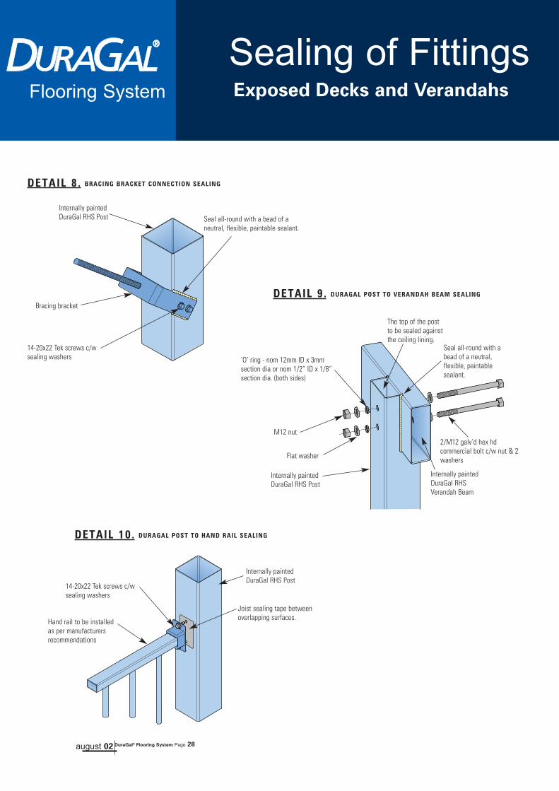
DETAIL 10. DURAGAL POST TO HAND RAIL SEALING
Joist sealing tape betweenoverlapping surfaces.
14-20x22 Tek screws c/wsealing washers
Hand rail to be installedas per manufacturersrecommendations
Internally paintedDuraGal RHS Post
Flooring System
DETAIL 8. BRACING BRACKET CONNECTION SEALING
DETAIL 9. DURAGAL POST TO VERANDAH BEAM SEALING
14-20x22 Tek screws c/wsealing washers
Seal all-round with a bead of aneutral, flexible, paintable sealant.
Seal all-round with abead of a neutral,flexible, paintablesealant.
The top of the postto be sealed againstthe ceiling lining.
Bracing bracket
Internally paintedDuraGal RHSVerandah Beam
2/M12 galv’d hex hdcommercial bolt c/w nut & 2washers
‘O’ ring - nom 12mm ID x 3mmsection dia or nom 1/2” ID x 1/8”section dia. (both sides)
M12 nut
Flat washer
Internally paintedDuraGal RHS Post
Internally paintedDuraGal RHS Post
august 02 DuraGal® Flooring System Page 28
Sealing of FittingsExposed Decks and Verandahs
august 02 DuraGal® Flooring System Page 29
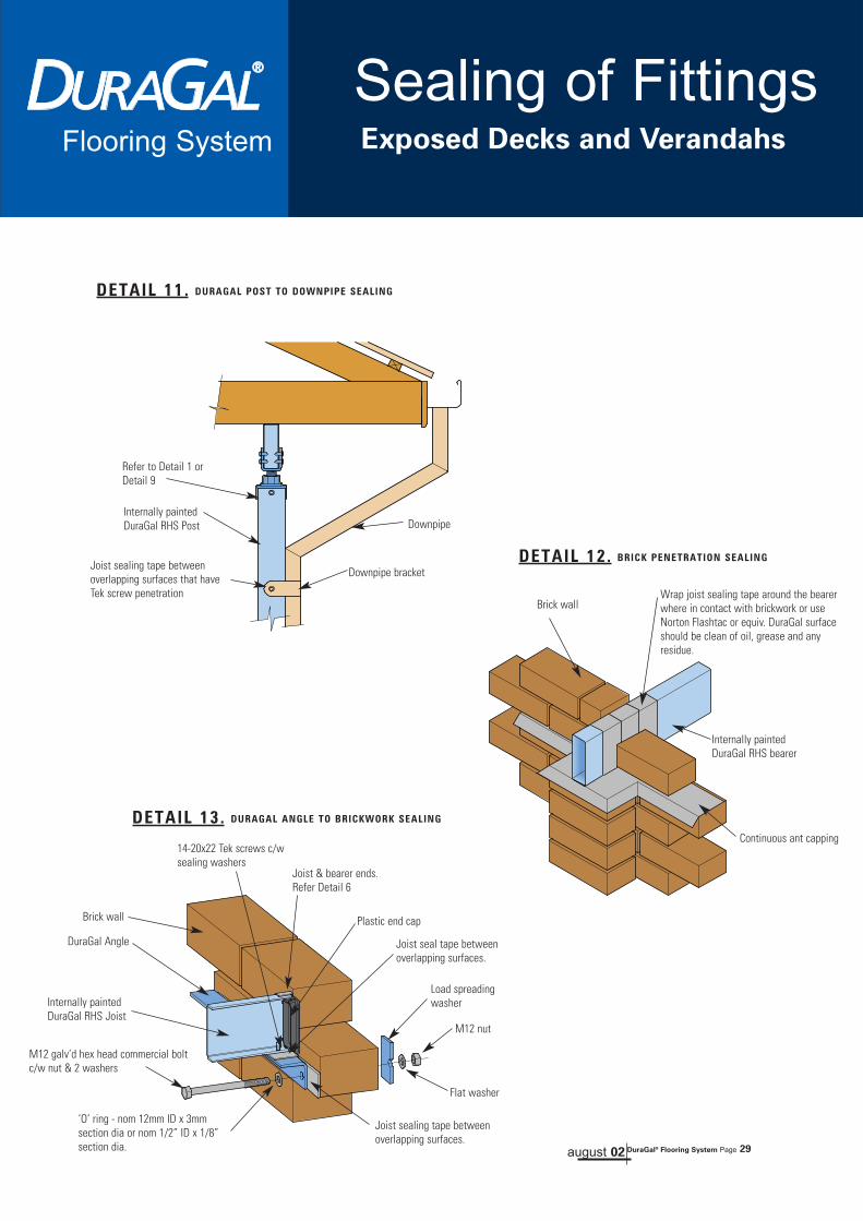
DETAIL 12. BRICK PENETRATION SEALING
DETAIL 13. DURAGAL ANGLE TO BRICKWORK SEALING
DETAIL 11. DURAGAL POST TO DOWNPIPE SEALING
Joist sealing tape betweenoverlapping surfaces that haveTek screw penetration
M12 galv’d hex head commercial boltc/w nut & 2 washers
‘O’ ring - nom 12mm ID x 3mmsection dia or nom 1/2” ID x 1/8”section dia.
Wrap joist sealing tape around the bearerwhere in contact with brickwork or useNorton Flashtac or equiv. DuraGal surfaceshould be clean of oil, grease and anyresidue.
M12 nut
Flat washer
Load spreadingwasher
Downpipe
Downpipe bracket
Internally paintedDuraGal RHS Post
Refer to Detail 1 orDetail 9
Joist & bearer ends.Refer Detail 6
Joist sealing tape betweenoverlapping surfaces.
Joist seal tape betweenoverlapping surfaces.
14-20x22 Tek screws c/wsealing washers
Internally paintedDuraGal RHS Joist
Internally paintedDuraGal RHS bearer
Continuous ant capping
Plastic end cap
DuraGal Angle
Brick wall
Brick wall
Flooring System
Sealing of FittingsExposed Decks and Verandahs

Nailing & Cutting Flooring System
Nailing of SheetFlooring toDuraGal® Joists
Sheet flooring can be successfully glued and nailed toboth 1.6 and 2.0mm DuraGal joists. Most nailing toolsincluding Duo-Fast® and Max®, or equivalent, have beensuccessfully trialed using the manufacturersrecommended hard steel end twist nail.
Most reputable building adhesives work on steel joistsand should be applied as per manufacturersrecommendations to dry joists.
To date, the best results have been obtained by usingthe Duo-Fast coil nailing tool with a 32mm hard steel endtwist nail.
Details are:-
TOOL: Duo-Fast® Model KD 655 BII, 665a or 750b
NAIL: Duo-Fast® C25 / 32 SH Dac Con Hard Steel Twist Nail.
Notes:Sheet flooring can also be glued and screwed usingBuildex® WingTek screws (or equivalent) and is therecommended method for joists with wall thicknessgreater than 2.0mm.
Nailing of TimberDecking toDuraGal® Joists
External timber decking can be nailed to both 1.6 and2.0mm DuraGal Joists. When using hardwood or treatedtimber decking, the best results to date have beenobtained from the Duo-fast® Coil nailing tool and also aMax® Coil nailing tool with 38mm long 304 stainlesssteel hardened twist nails. Details for external fixing are:
TOOL: Max® Tool Model CN-650M-FAP50V9NAIL: Max® Nail 2.5 x 38mm long 304 stainless
steel hardened twist nail.
TOOL: Duo-fast® Model KD 650bII, 665a or 750bNAIL: Duo-fast® C25 /32 SH Dac Con Hard Steel
Twist Nail.
Notes:1. To reduce the risk of corrosion, joist sealing tapeshould be used on the top of the joists for all externaltimber decks or verandahs as shown in Detail 4 page 26.2. The use of screws to attach timber decking to joists onexternal decks and verandahs is not recommended.
Nailing Guidelines
• The joist weld seam, (internal weld bead), should be placed down onto the bearer, during installation.
• Do not attempt to nail through joiners, nail either side of them.
• The air pressure should be a constant 710 minimum to 800kPa maximum, (105 to 120 PSI).
• Nailing tool must be perpendicular to sheet and firmly held.
• Ensure nailing tool is on sequential action.
• Bump fire action must never be used.
Cutting DuraGal®
The cutting of steel on site has been made easier withthe introduction of a new portable cold cut docking sawthat has been introduced by Makita® (4130).The saw is lighter, and the cold cut produces a burr-freecut (therefore safer), without zinc burn.
For further information on the Makita® 4130 saw contactyour local Makita® dealer. Other recommended methodsinclude drop saws, circular hand saws and anglegrinders fitted with the appropriate steel cutting disc.
Flooring System
DuraGal®
august 02 DuraGal® Flooring System Page 30
This publication has been prepared by OneSteel Market Mills an operating business group of which OneSteel Trading Pty Limited ABN 50 007 519 646 is a part of. Please note that the specifications andtechnical data referred to in this publication are subject to change and/or variation or improvement without notice and no warranty as to their suitability is made. Users of this publication - to ensure accuracy
and adequacy for their purposes - are requested to check the information in this publication to satisfy themselves as to its appropriateness and not to rely on the information without first doing so. Unlessrequired by law, the company cannot accept any responsibility for any loss, damage or consequence resulting from the use of this publication. Photographs shown are representative only of typical
applications, current at August 2002. This brochure is not an offer to trade and shall not form any part of the trading terms in any transaction. Copyright 2002 OneSteel Trading Pty Limited ABN 50 007 519 646.
Issue 5 August 2002. OneSteel Trading Pty Limited ABN 50 007 519 646. Registered Trademark; DuraGal
Flooring System
august 02 DuraGal® Flooring System Page 32
9 3 2 0 0 7 5 0 2 7 3 9 1
FOR MORE INFORMATION CONTACT
OneSteel Direct39-45 Flagstaff Road Port Kembla NSW 2505
Locked Bag 8825 South Coast Mail Centre NSW 2521Telephone: 1800 1 STEEL (1800 1 78335) Facsimile: 1800 101 141
Email: [email protected]: www.onesteel.com
Recommended