Accelerate your business potential with innovative IT infrastructure
DtCNETCONNECT
Data Network Product CatalogDtC® Networking
Introducing The New DtC Networking System
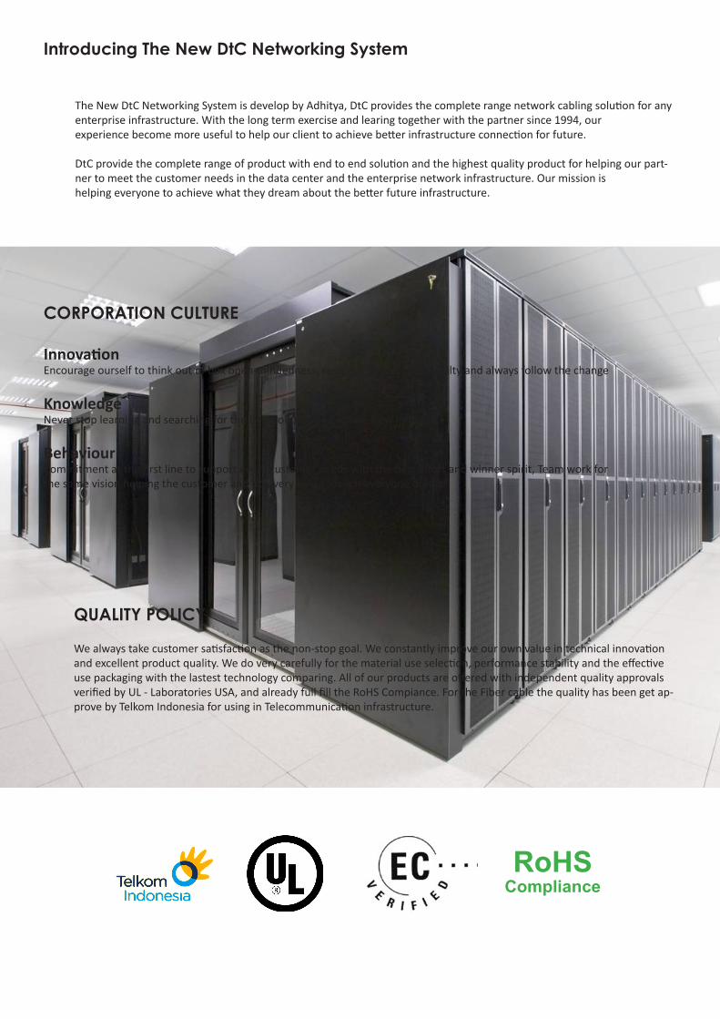
The New DtC Networking System is develop by Adhitya, DtC provides the complete range network cabling solution for any enterprise infrastructure. With the long term exercise and learing together with the partner since 1994, our experience become more useful to help our client to achieve better infrastructure connection for future.
DtC provide the complete range of product with end to end solution and the highest quality product for helping our part-ner to meet the customer needs in the data center and the enterprise network infrastructure. Our mission is helping everyone to achieve what they dream about the better future infrastructure.
CORPORATION CULTURE
InnovationEncourage ourself to think out of box open-mindedness, re-active behaviour flexibilty and always follow the change
Knowledge Never stop learning and searching for the best solution and future view minded
BehaviourCommitment at the first line to support every customer needs with the best effort and winner spirit, Team work for the same vision helping the customer and do every best to reach everyone dream
QUALITY POLICY
We always take customer satisfaction as the non-stop goal. We constantly improve our own value in technical innovation and excellent product quality. We do very carefully for the material use selection, performance stability and the effective use packaging with the lastest technology comparing. All of our products are offered with independent quality approvals verified by UL - Laboratories USA, and already full fill the RoHS Compiance. For the Fiber cable the quality has been get ap-prove by Telkom Indonesia for using in Telecommunication infrastructure.
RoHSCompliance
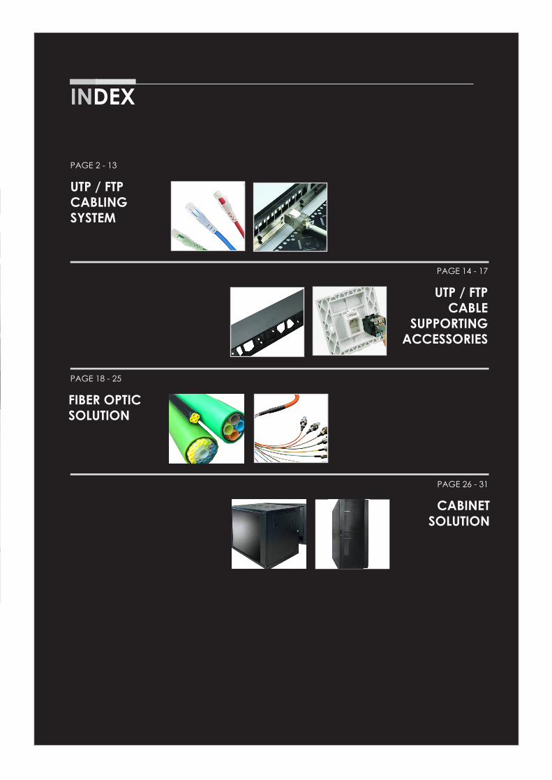
PAGE 2 - 13
PAGE 14 - 17
PAGE 26 - 31
PAGE 18 - 25
UTP / FTPCABLINGSYSTEM
UTP / FTPCABLE
SUPPORTINGACCESSORIES
CABINET SOLUTION
FIBER OPTIC SOLUTION
INDEX
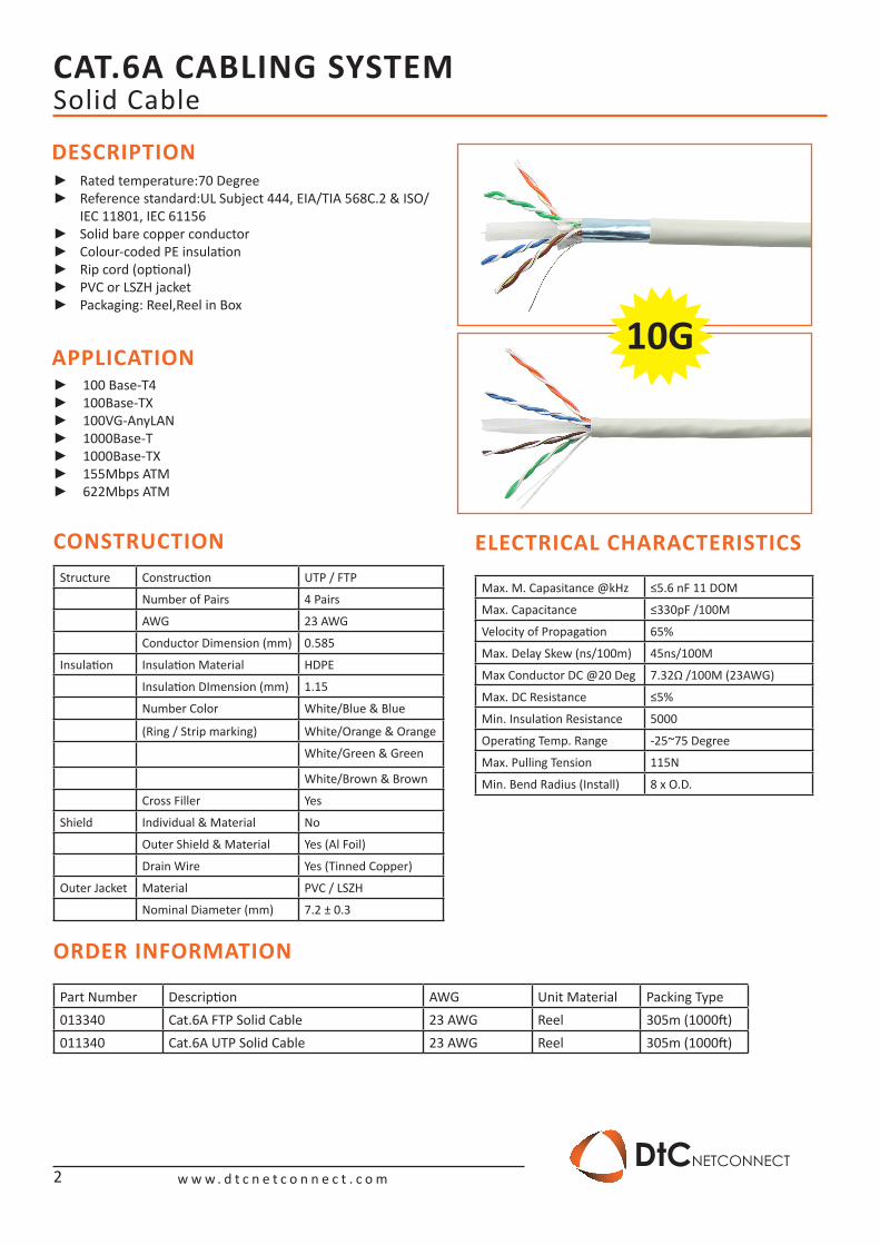
CAT.6A CABLING SYSTEM
w w w . d t c n e t c o n n e c t . c o mDtCNETCONNECT
10G
DESCRIPTION
APPLICATION
CONSTRUCTION
ORDER INFORMATION
ELECTRICAL CHARACTERISTICS
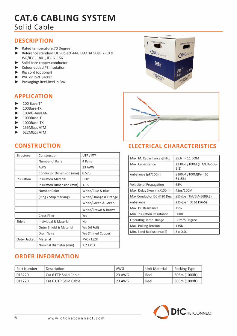
Rated temperature:70 Degree ►Reference standard:UL Subject 444, EIA/TIA 568C.2 & ISO/ ►IEC 11801, IEC 61156Solid bare copper conductor ►Colour-coded PE insulation ►Rip cord (optional) ►PVC or LSZH jacket ►Packaging: Reel,Reel in Box ►
100 Base-T4 ►100Base-TX ►100VG-AnyLAN ►1000Base-T ►1000Base-TX ►155Mbps ATM ►622Mbps ATM ►
Structure Construction UTP / FTP
Number of Pairs 4 Pairs
AWG 23 AWG
Conductor Dimension (mm) 0.585
Insulation Insulation Material HDPE
Insulation DImension (mm) 1.15
Number Color White/Blue & Blue
(Ring / Strip marking) White/Orange & Orange
White/Green & Green
White/Brown & Brown
Cross Filler Yes
Shield Individual & Material No
Outer Shield & Material Yes (Al Foil)
Drain Wire Yes (Tinned Copper)
Outer Jacket Material PVC / LSZH
Nominal Diameter (mm) 7.2 ± 0.3
Max. M. Capasitance @kHz ≤5.6 nF 11 DOM
Max. Capacitance ≤330pF /100M
Velocity of Propagation 65%
Max. Delay Skew (ns/100m) 45ns/100M
Max Conductor DC @20 Deg 7.32Ω /100M (23AWG)
Max. DC Resistance ≤5%
Min. Insulation Resistance 5000
Operating Temp. Range -25~75 Degree
Max. Pulling Tension 115N
Min. Bend Radius (Install) 8 x O.D.
Part Number Description AWG Unit Material Packing Type013340 Cat.6A FTP Solid Cable 23 AWG Reel 305m (1000ft)011340 Cat.6A UTP Solid Cable 23 AWG Reel 305m (1000ft)
Solid Cable
2
CAT.6A CABLING SYSTEM
w w w . d t c n e t c o n n e c t . c o mDtCNETCONNECT
10G
DESCRIPTION FEATURE & BENEFITS
TIA/EIA 568-C.2 ELECTRICAL CHARACTERISTICS
ORDER INFORMATION
Part Number Description Unit Material Packing Type0123x1 Cat.6A Patch Cord 1m Plastic Bag 1 pc0123x2 Cat.6A Patch Cord 2m Plastic bag 1 pc0123x3 Cat.6A Patch Cord 3m Plastic bag 1 pc
X = Color (2= Blue, 3= Red)
Solid Cable & Patch Cord
Frequency Impedance ATT RL NEXT PSNEXT ELFEX TCL DELAY PSANEXT PSACCRF
MHz Ohm Db/100m Db Db Db Db/100m Db Ns/100m Db Db
16 100±15 7.5 20 54.2 54.2 43.7 38 543 67 54.1
20 100±15 8.4 20 52.8 52.8 41.8 37 542 67 52.2
31 100±15 10.5 18.6 50 49 37.9 35.1 540 67 48.3
125 100±20 21.5 14.4 40.8 40.8 25.9 29 537 61 36.3
250 100±22 31.1 12.3 36.3 36.3 19.8 26 536 56.5 30.2
300 100±25 34.3 11.8 35.1 35.1 18.3 25.2 536 55.3 28.7
400 100±25 40.2 10.9 33.3 33.3 15.8 24 535.8 53.5 26.2
500 100±25 43.3 10.2 31.8 31.8 13.8 `23.0 535.6 52.0 24.2
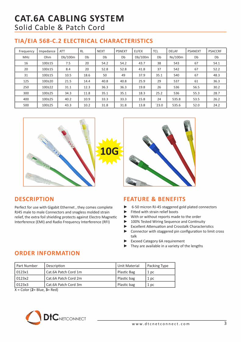
Perfect for use with Gigabit Ethernet , they comes complete RJ45 male to male Connectors and snagless molded strain relief, the extra foil shielding protects against Electro Magnetic Interference (EMI) and Radio Frequency Interference (RFI)
6-50 micron RJ-45 staggered gold plated connectors ►Fitted with strain relief boots ►With or without reports made to the order ►100% Tested Wiring Sequence and Continuity ►Excellent Attenuation and Crosstalk Characteristics ►Connector with staggered pin configuration to limit cross ►talkExceed Category 6A requirement ►They are available in a variety of the lengths ►
3
CAT.6A CABLING SYSTEM
w w w . d t c n e t c o n n e c t . c o mDtCNETCONNECT
DESCRIPTION
APPLICATION
CONSTRUCTION
INSTALLMENT INSTRUCTIONS
10G
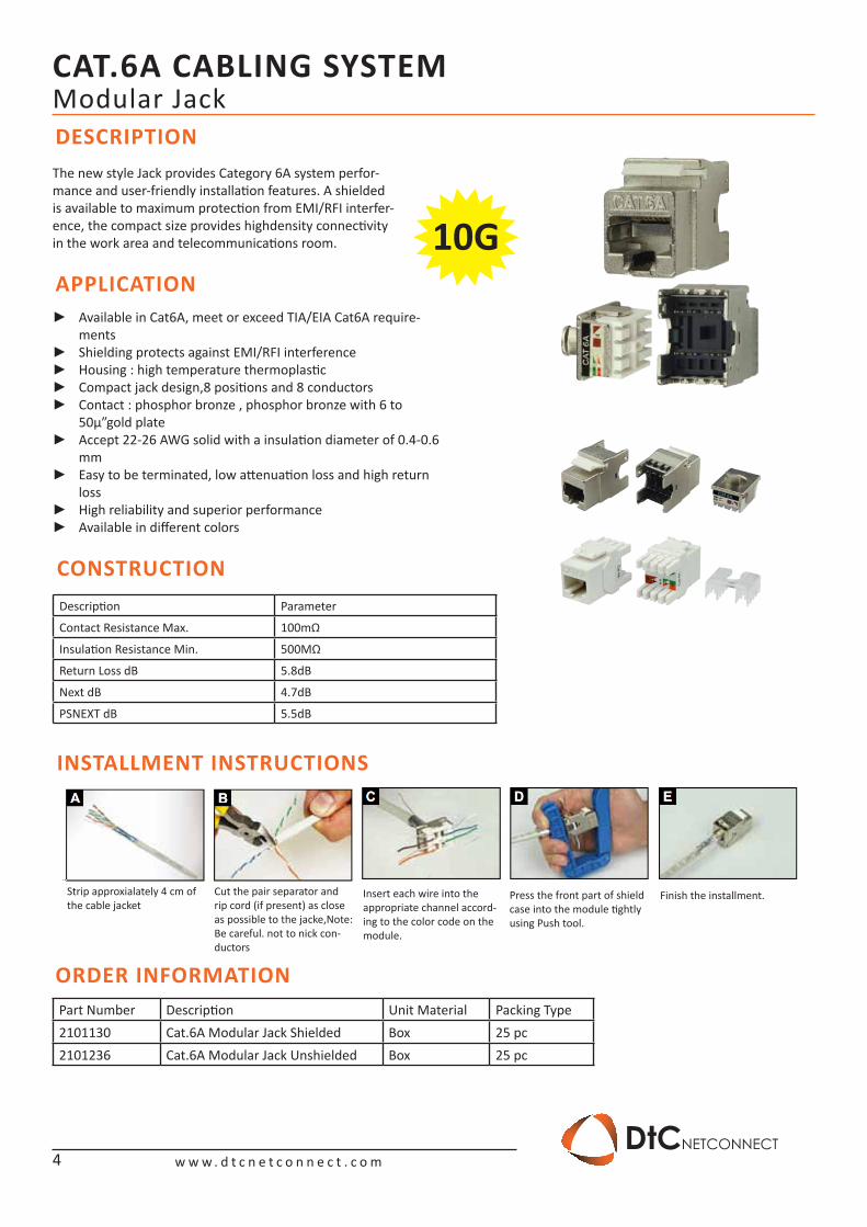
The new style Jack provides Category 6A system perfor-mance and user-friendly installation features. A shielded is available to maximum protection from EMI/RFI interfer-ence, the compact size provides highdensity connectivity in the work area and telecommunications room.
Available in Cat6A, meet or exceed TIA/EIA Cat6A require- ►mentsShielding protects against EMI/RFI interference ►Housing : high temperature thermoplastic ►Compact jack design,8 positions and 8 conductors ►Contact : phosphor bronze , phosphor bronze with 6 to ►50μ”gold plateAccept 22-26 AWG solid with a insulation diameter of 0.4-0.6 ►mmEasy to be terminated, low attenuation loss and high return ►lossHigh reliability and superior performance ►Available in different colors ►
Modular Jack
Description Parameter
Contact Resistance Max. 100mΩ
Insulation Resistance Min. 500MΩ
Return Loss dB 5.8dB
Next dB 4.7dB
PSNEXT dB 5.5dB
Strip approxialately 4 cm of the cable jacket
Cut the pair separator and rip cord (if present) as close as possible to the jacke,Note: Be careful. not to nick con-ductors
Insert each wire into the appropriate channel accord-ing to the color code on the module.
Press the front part of shield case into the module tightly using Push tool.
Finish the installment.
ORDER INFORMATIONPart Number Description Unit Material Packing Type2101130 Cat.6A Modular Jack Shielded Box 25 pc2101236 Cat.6A Modular Jack Unshielded Box 25 pc
4
CAT.6A CABLING SYSTEM
w w w . d t c n e t c o n n e c t . c o mDtCNETCONNECT
10G
Patch Panel
Part Number Description Unit Material Packing Type11113-6 Cat.6A Patch Panel Shielded 48 Port Box 1 pc11123-6 Cat.6A Patch Panel Unshielded 48 Port Box 1 pc11103-5 Cat.6A Patch Panel Unshielded 24 port Box 1 pc
DESCRIPTION FEATURE & BENEFITS
ORDER INFORMATION
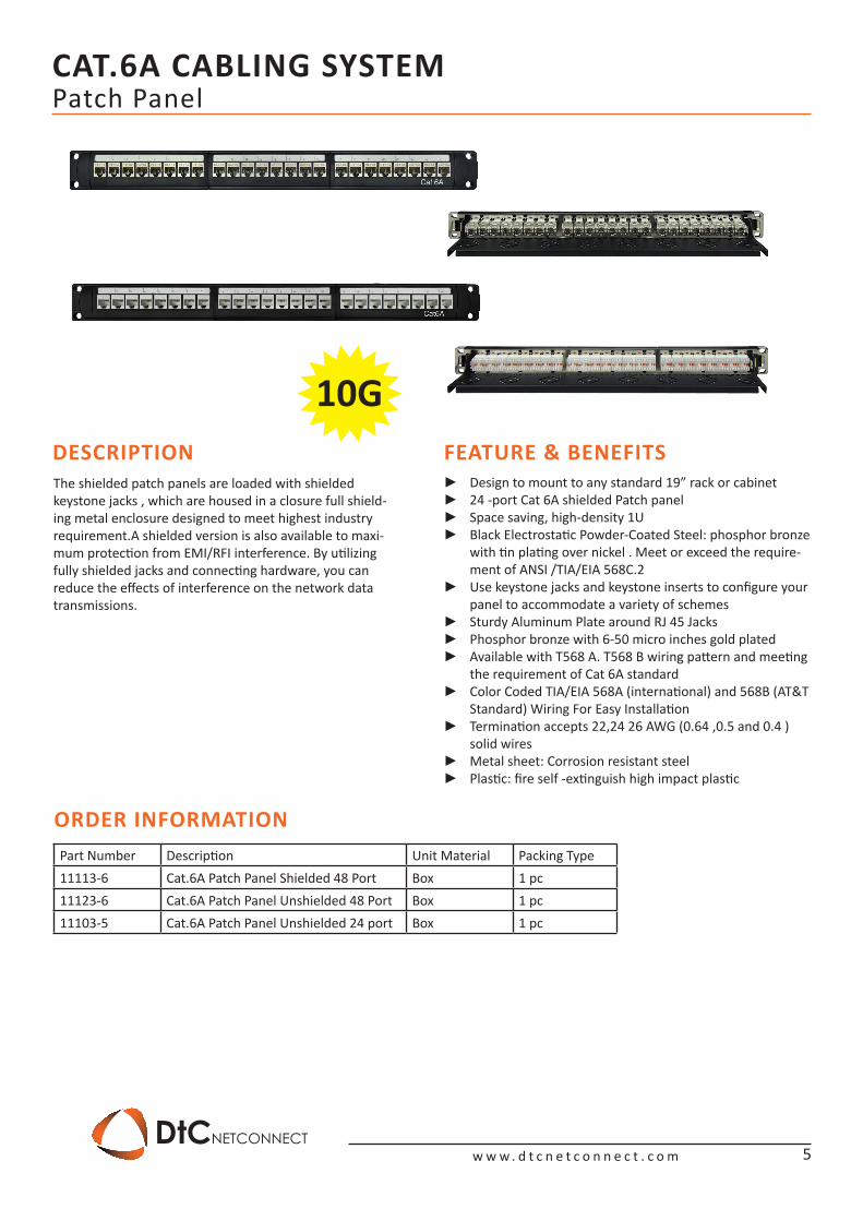
The shielded patch panels are loaded with shielded keystone jacks , which are housed in a closure full shield-ing metal enclosure designed to meet highest industry requirement.A shielded version is also available to maxi-mum protection from EMI/RFI interference. By utilizing fully shielded jacks and connecting hardware, you can reduce the effects of interference on the network data transmissions.
Design to mount to any standard 19” rack or cabinet ►24 -port Cat 6A shielded Patch panel ►Space saving, high-density 1U ►Black Electrostatic Powder-Coated Steel: phosphor bronze ►with tin plating over nickel . Meet or exceed the require-ment of ANSI /TIA/EIA 568C.2Use keystone jacks and keystone inserts to configure your ►panel to accommodate a variety of schemesSturdy Aluminum Plate around RJ 45 Jacks ►Phosphor bronze with 6-50 micro inches gold plated ►Available with T568 A. T568 B wiring pattern and meeting ►the requirement of Cat 6A standardColor Coded TIA/EIA 568A (international) and 568B (AT&T ►Standard) Wiring For Easy InstallationTermination accepts 22,24 26 AWG (0.64 ,0.5 and 0.4 ) ►solid wiresMetal sheet: Corrosion resistant steel ►Plastic: fire self -extinguish high impact plastic ►
5
CAT.6 CABLING SYSTEM
w w w . d t c n e t c o n n e c t . c o mDtCNETCONNECT
Solid Cable
DESCRIPTION
APPLICATION
CONSTRUCTION
ORDER INFORMATION
ELECTRICAL CHARACTERISTICS
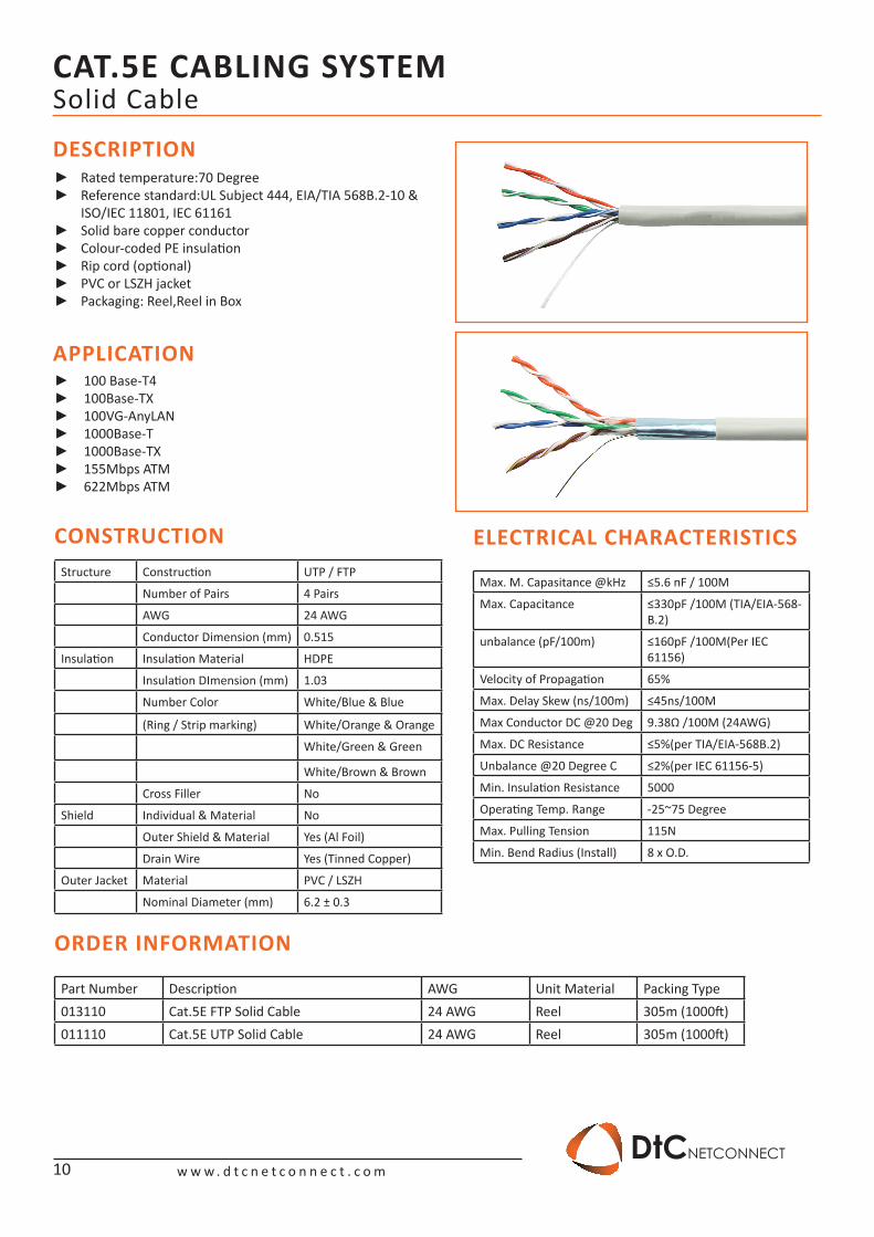
Rated temperature:70 Degree ►Reference standard:UL Subject 444, EIA/TIA 568B.2-10 & ►ISO/IEC 11801, IEC 61156Solid bare copper conductor ►Colour-coded PE insulation ►Rip cord (optional) ►PVC or LSZH jacket ►Packaging: Reel,Reel in Box ►
100 Base-T4 ►100Base-TX ►100VG-AnyLAN ►1000Base-T ►1000Base-TX ►155Mbps ATM ►622Mbps ATM ►
Structure Construction UTP / FTP
Number of Pairs 4 Pairs
AWG 23 AWG
Conductor Dimension (mm) 0.575
Insulation Insulation Material HDPE
Insulation DImension (mm) 1.15
Number Color White/Blue & Blue
(Ring / Strip marking) White/Orange & Orange
White/Green & Green
White/Brown & Brown
Cross Filler Yes
Shield Individual & Material No
Outer Shield & Material Yes (Al Foil)
Drain Wire Yes (Tinned Copper)
Outer Jacket Material PVC / LSZH
Nominal Diameter (mm) 7.2 ± 0.3
Max. M. Capasitance @kHz ≤5.6 nF 11 DOM
Max. Capacitance ≤330pF /100M (TIA/EIA-568-B.2)
unbalance (pF/100m) ≤160pF /100M(Per IEC 61156)
Velocity of Propagation 65%
Max. Delay Skew (ns/100m) 45ns/100M
Max Conductor DC @20 Deg ≤5%(per TIA/EIA-568B.2)
unbalance ≤2%(per IEC 61156-5)
Max. DC Resistance ≤5%
Min. Insulation Resistance 5000
Operating Temp. Range -25~75 Degree
Max. Pulling Tension 115N
Min. Bend Radius (Install) 8 x O.D.
Part Number Description AWG Unit Material Packing Type013220 Cat.6 FTP Solid Cable 23 AWG Reel 305m (1000ft)011220 Cat.6 UTP Solid Cable 23 AWG Reel 305m (1000ft)
6

CAT.6 CABLING SYSTEM
w w w . d t c n e t c o n n e c t . c o mDtCNETCONNECT
Solid Cable & Patch Cord
DESCRIPTION FEATURE & BENEFITS
TIA/EIA 568-B.2 ELECTRICAL CHARACTERISTICS
ORDER INFORMATION
Part Number Description Unit Material Packing Type0122x1 Cat.6 Patch Cord 1m Plastic Bag 1 pc0122x2 Cat.6 Patch Cord 2m Plastic bag 1 pc0122x3 Cat.6 Patch Cord 3m Plastic bag 1 pc
X = Color (2= Blue, 3= Red)
Frequency Impedance ATT RL NEXT PSNEXT ELFEX PSELFEXT PD
MHz Ohm Db/100m Db Db Db Db/100m Db/100m Db/100m
1 100±15 2.0 20 74.3 72.3 67.8 64.8 570
10 100±15 6.0 25 59.3 57.3 47.8 44.8 545.4
16 100±15 7.6 25 56.2 54.2 43.7 40.7 543
20 100±15 8.5 25 54.8 52.8 41.8 38.8 542
31 100±15 10.7 23.6 51.9 49.9 37.9 34.9 540.4
62.5 100±15 15.4 21.5 47.4 45.4 31.9 28.9 538.6
100 100±15 19.8 20.1 44.3 42.3 27.8 24.8 537.6
200 100±22 29.0 18.0 39.8 37.8 21.8 18.8 536.5
250 100±22 32.8 17.3 38.3 36.3 19.8 16.8 536.3
Perfect for use with Gigabit Ethernet , they comes complete RJ45 male to male Connectors and snagless molded strain relief, the extra foil shielding protects against Electro Magnetic Interference (EMI) and Radio Frequency Interference (RFI)
6-50 micron RJ-45 staggered gold plated connectors ►Fitted with strain relief boots ►With or without reports made to the order ►100% Tested Wiring Sequence and Continuity ►Excellent Attenuation and Crosstalk Characteristics ►Connector with staggered pin configuration to limit cross ►talkExceed Category 6 requirement ►They are available in a variety of the lengths ►
7
CAT.6 CABLING SYSTEM
w w w . d t c n e t c o n n e c t . c o mDtCNETCONNECT
Modular JackDESCRIPTION
APPLICATION
CONSTRUCTION
INSTALLMENT INSTRUCTIONS
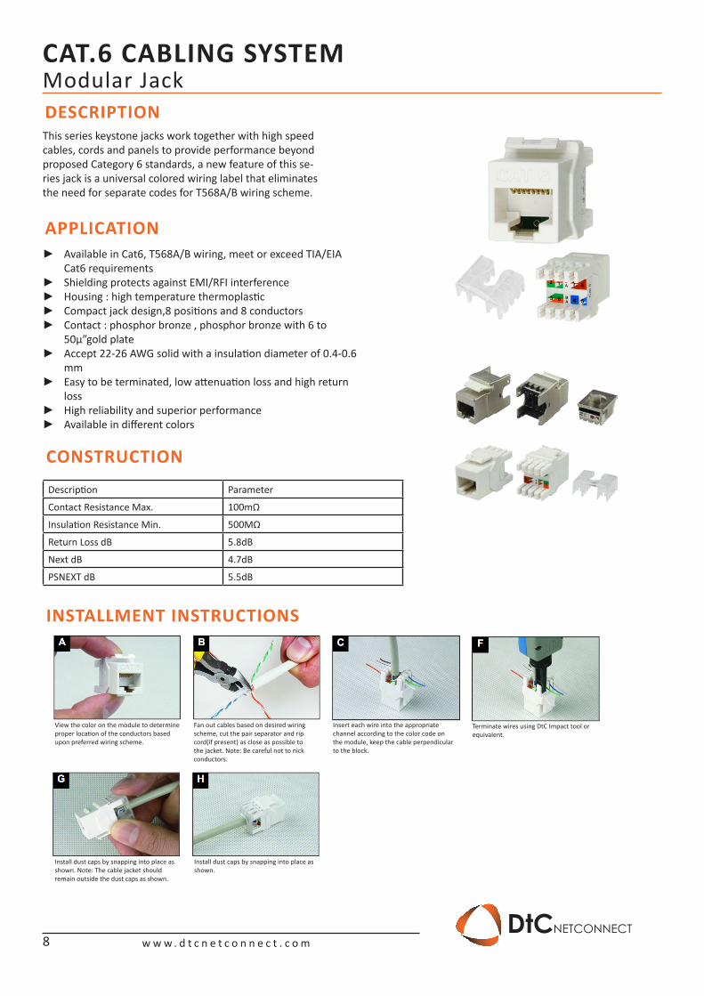
This series keystone jacks work together with high speed cables, cords and panels to provide performance beyond proposed Category 6 standards, a new feature of this se-ries jack is a universal colored wiring label that eliminates the need for separate codes for T568A/B wiring scheme.
Available in Cat6, T568A/B wiring, meet or exceed TIA/EIA ►Cat6 requirementsShielding protects against EMI/RFI interference ►Housing : high temperature thermoplastic ►Compact jack design,8 positions and 8 conductors ►Contact : phosphor bronze , phosphor bronze with 6 to ►50μ”gold plateAccept 22-26 AWG solid with a insulation diameter of 0.4-0.6 ►mmEasy to be terminated, low attenuation loss and high return ►lossHigh reliability and superior performance ►Available in different colors ►
Description Parameter
Contact Resistance Max. 100mΩ
Insulation Resistance Min. 500MΩ
Return Loss dB 5.8dB
Next dB 4.7dB
PSNEXT dB 5.5dB
View the color on the module to determine proper location of the conductors based upon preferred wiring scheme.
Install dust caps by snapping into place asshown. Note: The cable jacket should remain outside the dust caps as shown.
Install dust caps by snapping into place asshown.
Fan out cables based on desired wiring scheme, cut the pair separator and rip cord(if present) as close as possible to the jacket. Note: Be careful not to nick conductors.
Insert each wire into the appropriate channel according to the color code on the module, keep the cable perpendicular to the block.
Terminate wires using DtC Impact tool or equivalent.
8
CAT.6 CABLING SYSTEM
w w w . d t c n e t c o n n e c t . c o mDtCNETCONNECT
Patch Panel & Modular Jack
ORDER INFORMATIONPart Number Description Unit Material Packing Type2101120 Cat.6 Modular Jack Shielded Box 25 pc210122x Cat.6 Modular Jack Unshielded Box 25 pc
Part Number Description Unit Material Packing Type11112-6 Cat.6 Patch Panel Shielded 48 Port Box 1 pc11122-6 Cat.6 Patch Panel Unshielded 48 Port Box 1 pc11112-5 Cat.6 Patch Panel Unshielded 24 Port Box 1 pc
DESCRIPTION FEATURE & BENEFITS
ORDER INFORMATION
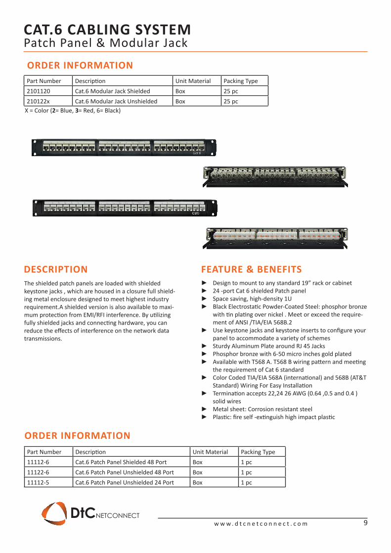
The shielded patch panels are loaded with shielded keystone jacks , which are housed in a closure full shield-ing metal enclosure designed to meet highest industry requirement.A shielded version is also available to maxi-mum protection from EMI/RFI interference. By utilizing fully shielded jacks and connecting hardware, you can reduce the effects of interference on the network data transmissions.
Design to mount to any standard 19” rack or cabinet ►24 -port Cat 6 shielded Patch panel ►Space saving, high-density 1U ►Black Electrostatic Powder-Coated Steel: phosphor bronze ►with tin plating over nickel . Meet or exceed the require-ment of ANSI /TIA/EIA 568B.2Use keystone jacks and keystone inserts to configure your ►panel to accommodate a variety of schemesSturdy Aluminum Plate around RJ 45 Jacks ►Phosphor bronze with 6-50 micro inches gold plated ►Available with T568 A. T568 B wiring pattern and meeting ►the requirement of Cat 6 standardColor Coded TIA/EIA 568A (international) and 568B (AT&T ►Standard) Wiring For Easy InstallationTermination accepts 22,24 26 AWG (0.64 ,0.5 and 0.4 ) ►solid wiresMetal sheet: Corrosion resistant steel ►Plastic: fire self -extinguish high impact plastic ►
9
X = Color (2= Blue, 3= Red, 6= Black)
CAT.5E CABLING SYSTEM
w w w . d t c n e t c o n n e c t . c o mDtCNETCONNECT
Solid Cable
DESCRIPTION
APPLICATION
CONSTRUCTION
ORDER INFORMATION
ELECTRICAL CHARACTERISTICS
Rated temperature:70 Degree ►Reference standard:UL Subject 444, EIA/TIA 568B.2-10 & ►ISO/IEC 11801, IEC 61161Solid bare copper conductor ►Colour-coded PE insulation ►Rip cord (optional) ►PVC or LSZH jacket ►Packaging: Reel,Reel in Box ►
100 Base-T4 ►100Base-TX ►100VG-AnyLAN ►1000Base-T ►1000Base-TX ►155Mbps ATM ►622Mbps ATM ►
Structure Construction UTP / FTP
Number of Pairs 4 Pairs
AWG 24 AWG
Conductor Dimension (mm) 0.515
Insulation Insulation Material HDPE
Insulation DImension (mm) 1.03
Number Color White/Blue & Blue
(Ring / Strip marking) White/Orange & Orange
White/Green & Green
White/Brown & Brown
Cross Filler No
Shield Individual & Material No
Outer Shield & Material Yes (Al Foil)
Drain Wire Yes (Tinned Copper)
Outer Jacket Material PVC / LSZH
Nominal Diameter (mm) 6.2 ± 0.3
Max. M. Capasitance @kHz ≤5.6 nF / 100M
Max. Capacitance ≤330pF /100M (TIA/EIA-568-B.2)
unbalance (pF/100m) ≤160pF /100M(Per IEC 61156)
Velocity of Propagation 65%
Max. Delay Skew (ns/100m) ≤45ns/100M
Max Conductor DC @20 Deg 9.38Ω /100M (24AWG)
Max. DC Resistance ≤5%(per TIA/EIA-568B.2)
Unbalance @20 Degree C ≤2%(per IEC 61156-5)
Min. Insulation Resistance 5000
Operating Temp. Range -25~75 Degree
Max. Pulling Tension 115N
Min. Bend Radius (Install) 8 x O.D.
Part Number Description AWG Unit Material Packing Type013110 Cat.5E FTP Solid Cable 24 AWG Reel 305m (1000ft)011110 Cat.5E UTP Solid Cable 24 AWG Reel 305m (1000ft)
10
CAT.5E CABLING SYSTEM
w w w . d t c n e t c o n n e c t . c o mDtCNETCONNECT
Solid Cable & Patch Cord
DESCRIPTION FEATURE & BENEFITS
TIA/EIA 568-B.2 ELECTRICAL CHARACTERISTICS
ORDER INFORMATION
Part Number Description Unit Material Packing Type012121 Cat.5E Patch Cord 1m Plastic Bag 1 pc012122 Cat.5E Patch Cord 2m Plastic bag 1 pc012123 Cat.5E Patch Cord 3m Plastic bag 1 pc
Frequency Impedance ATT RL NEXT PSNEXT ELFEX PSELFEXT PD
MHz Ohm Db/100m Db Db Db Db/100m Db/100m Db/100m
1 100±15 2.0 20 65.3 62.3 63.8 60.8 570
8 100±15 5.8 24.5 51.8 48.8 45.7 42.7 546.7
10 100±15 6.5 25 50.3 47.3 42.8 40.8 545.4
16 100±15 8.2 25 47.2 44.2 39.7 36.7 543
20 100±15 9.3 25 45.8 42.8 37.8 34.8 542
25 100±15 10.4 24.3 44.3 41.3 35.8 32.8 541.2
31 100±15 11.7 23.6 42.9 39.9 33.9 30.9 540.4
62.5 100±15 17 21.5 38.4 35.4 27.9 24.9 538.6
100 100±15 22 20.1 35.3 32.3 23.8 20.8 537.6
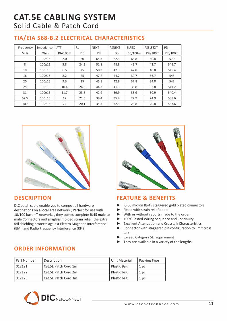
DtC patch cable enable you to connect all hardwaredestinations on a local area network , Perfect for use with 10/100 base –T networks , they comes complete RJ45 male to male Connectors and snagless molded strain relief ,the extra foil shielding protects against Electro Magnetic Interference (EMI) and Radio Frequency Interference (RFI)
6-50 micron RJ-45 staggered gold plated connectors ►Fitted with strain relief boots ►With or without reports made to the order ►100% Tested Wiring Sequence and Continuity ►Excellent Attenuation and Crosstalk Characteristics ►Connector with staggered pin configuration to limit cross ►talkExceed Category 5E requirement ►They are available in a variety of the lengths ►
11
CAT.5E CABLING SYSTEM
w w w . d t c n e t c o n n e c t . c o mDtCNETCONNECT
Modular JackDESCRIPTION
APPLICATION
CONSTRUCTION
INSTALLMENT INSTRUCTIONS
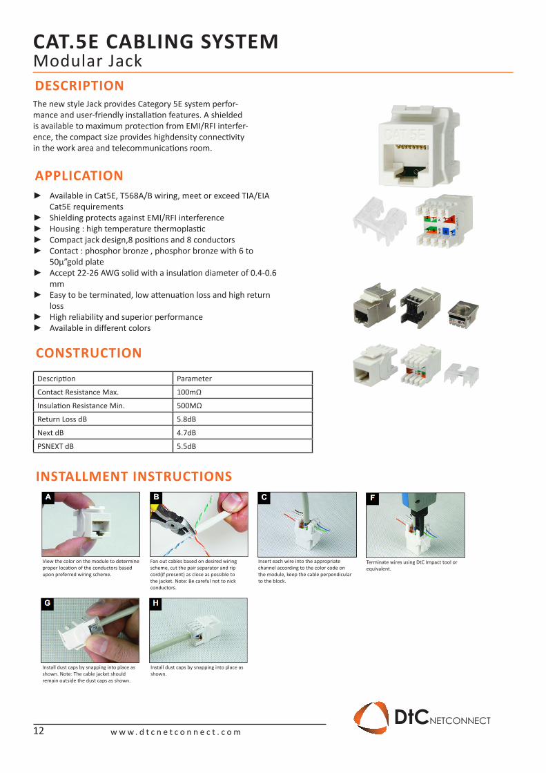
The new style Jack provides Category 5E system perfor-mance and user-friendly installation features. A shielded is available to maximum protection from EMI/RFI interfer-ence, the compact size provides highdensity connectivity in the work area and telecommunications room.
Available in Cat5E, T568A/B wiring, meet or exceed TIA/EIA ►Cat5E requirementsShielding protects against EMI/RFI interference ►Housing : high temperature thermoplastic ►Compact jack design,8 positions and 8 conductors ►Contact : phosphor bronze , phosphor bronze with 6 to ►50μ”gold plateAccept 22-26 AWG solid with a insulation diameter of 0.4-0.6 ►mmEasy to be terminated, low attenuation loss and high return ►lossHigh reliability and superior performance ►Available in different colors ►
Description Parameter
Contact Resistance Max. 100mΩ
Insulation Resistance Min. 500MΩ
Return Loss dB 5.8dB
Next dB 4.7dB
PSNEXT dB 5.5dB
View the color on the module to determine proper location of the conductors based upon preferred wiring scheme.
Install dust caps by snapping into place asshown. Note: The cable jacket should remain outside the dust caps as shown.
Install dust caps by snapping into place asshown.
Fan out cables based on desired wiring scheme, cut the pair separator and rip cord(if present) as close as possible to the jacket. Note: Be careful not to nick conductors.
Insert each wire into the appropriate channel according to the color code on the module, keep the cable perpendicular to the block.
Terminate wires using DtC Impact tool or equivalent.
12
CAT.5E CABLING SYSTEM
w w w . d t c n e t c o n n e c t . c o mDtCNETCONNECT
Patch Panel & Modular Jack
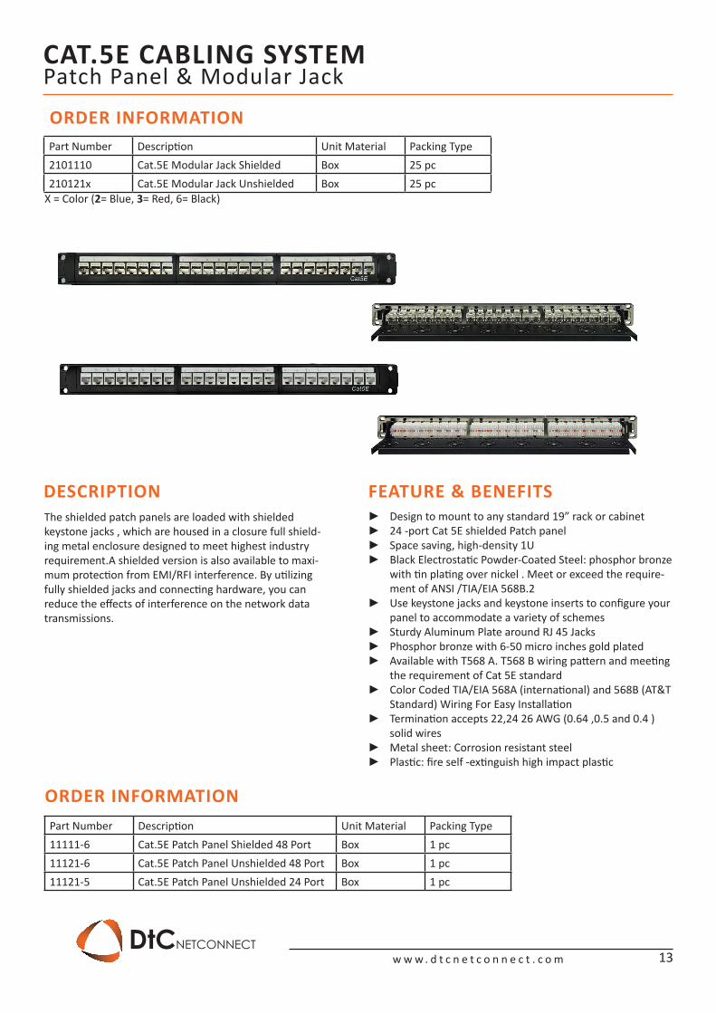
ORDER INFORMATIONPart Number Description Unit Material Packing Type2101110 Cat.5E Modular Jack Shielded Box 25 pc210121x Cat.5E Modular Jack Unshielded Box 25 pc
Part Number Description Unit Material Packing Type11111-6 Cat.5E Patch Panel Shielded 48 Port Box 1 pc11121-6 Cat.5E Patch Panel Unshielded 48 Port Box 1 pc11121-5 Cat.5E Patch Panel Unshielded 24 Port Box 1 pc
DESCRIPTION FEATURE & BENEFITS
ORDER INFORMATION
The shielded patch panels are loaded with shielded keystone jacks , which are housed in a closure full shield-ing metal enclosure designed to meet highest industry requirement.A shielded version is also available to maxi-mum protection from EMI/RFI interference. By utilizing fully shielded jacks and connecting hardware, you can reduce the effects of interference on the network data transmissions.
Design to mount to any standard 19” rack or cabinet ►24 -port Cat 5E shielded Patch panel ►Space saving, high-density 1U ►Black Electrostatic Powder-Coated Steel: phosphor bronze ►with tin plating over nickel . Meet or exceed the require-ment of ANSI /TIA/EIA 568B.2Use keystone jacks and keystone inserts to configure your ►panel to accommodate a variety of schemesSturdy Aluminum Plate around RJ 45 Jacks ►Phosphor bronze with 6-50 micro inches gold plated ►Available with T568 A. T568 B wiring pattern and meeting ►the requirement of Cat 5E standardColor Coded TIA/EIA 568A (international) and 568B (AT&T ►Standard) Wiring For Easy InstallationTermination accepts 22,24 26 AWG (0.64 ,0.5 and 0.4 ) ►solid wiresMetal sheet: Corrosion resistant steel ►Plastic: fire self -extinguish high impact plastic ►
13
X = Color (2= Blue, 3= Red, 6= Black)
SUPPORTING ACCESSORIES
w w w . d t c n e t c o n n e c t . c o mDtCNETCONNECT
14
Faceplate UK / British Style
DESCRIPTION
DESCRIPTION
APPLICATION
APPLICATION
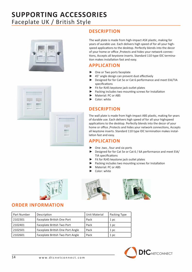
The wall plate is made from high-impact ABS plastic, making for years of durable use. Each delivers high speed of for all your highspeed applications to the desktop. Perfectly blends into the decor of your home or office ,Protects and hides your network connections, Accepts all keystone inserts. Standard 110 type IDC termination makes instal-lation fast and easy.
One .two , four and six ports ►Designed for for Cat 5e or Cat 6 / 6A performance and meet EIA/ ►TIA specificationsFit for RJ45 keystone jack outlet plates ►Packing includes two mounting screws for Installation ►Material: PC or ABS ►Color: white ►
One or Two ports faceplate ►45° angle design can prevent dust effectively ►Designed for for Cat 5e or Cat 6 performance and meet EIA/TIA ►specificationsFit for RJ45 keystone jack outlet plates ►Packing includes two mounting screws for Installation ►Material: PC or ABS ►Color: white ►
ORDER INFORMATION
Part Number Description Unit Material Packing Type2102301 Faceplate British One Port Pack 1 pc
2102401 Faceplate British Two Port Pack 1 pc2102501 Faceplate British One Port Angle Pack 1 pc2102601 Faceplate British Two Port Angle Pack 1 pc
The wall plate is made from high-impact ASX plastic, making for years of aurable use. Each delivers high speed of for all your high-speed applications to the desktop. Perfectly blends into the decor of your home or office ,Protects and hides your network connec-tions, Accepts all keystone inserts. Standard 110 type IDC termina-tion makes installation fast and easy.
SUPPORTING ACCESSORIES
w w w . d t c n e t c o n n e c t . c o mDtCNETCONNECT
15
Modular Plug RJ45 & Boot
DESCRIPTION
DESCRIPTION
APPLICATION
APPLICATION
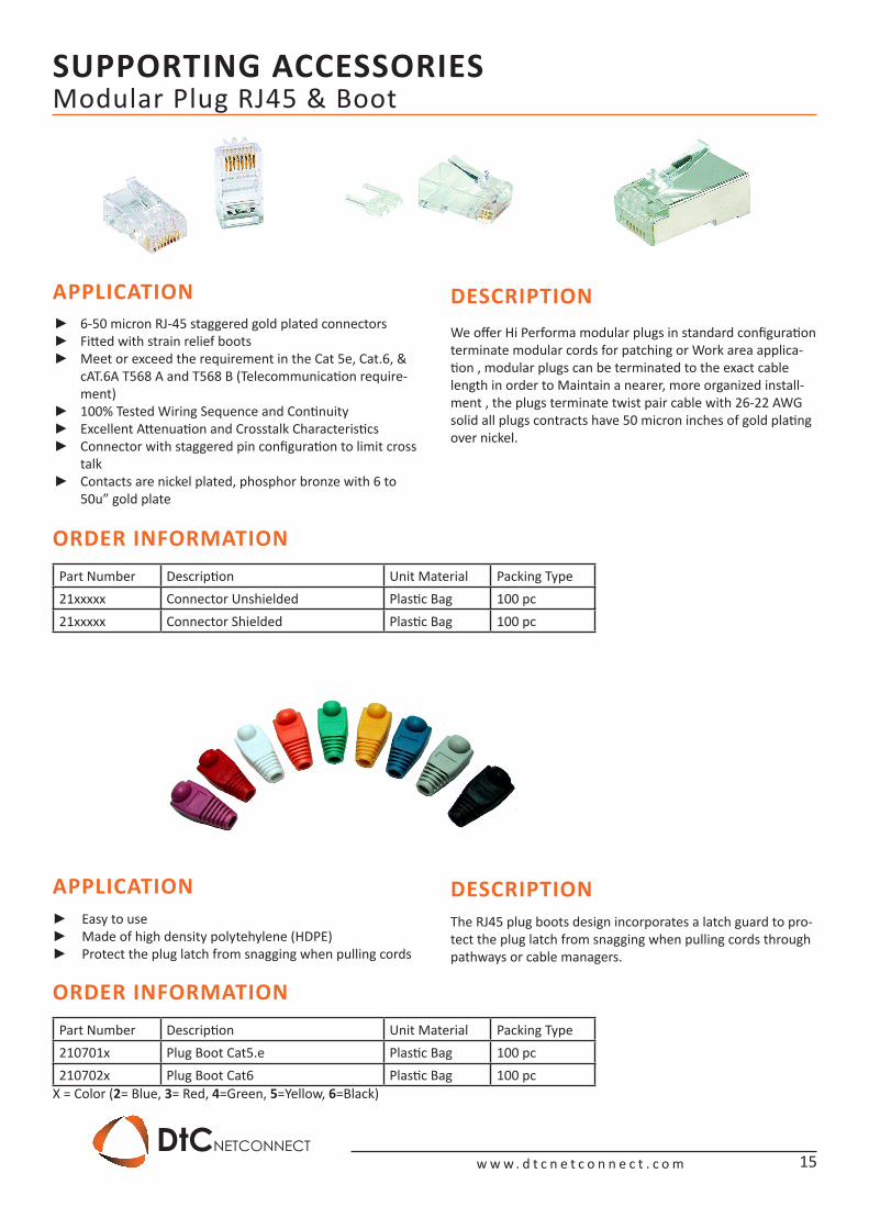
We offer Hi Performa modular plugs in standard configuration terminate modular cords for patching or Work area applica-tion , modular plugs can be terminated to the exact cable length in order to Maintain a nearer, more organized install-ment , the plugs terminate twist pair cable with 26-22 AWG solid all plugs contracts have 50 micron inches of gold plating over nickel.
The RJ45 plug boots design incorporates a latch guard to pro-tect the plug latch from snagging when pulling cords through pathways or cable managers.
6-50 micron RJ-45 staggered gold plated connectors ►Fitted with strain relief boots ►Meet or exceed the requirement in the Cat 5e, Cat.6, & ►cAT.6A T568 A and T568 B (Telecommunication require-ment)100% Tested Wiring Sequence and Continuity ►Excellent Attenuation and Crosstalk Characteristics ►Connector with staggered pin configuration to limit cross ►talkContacts are nickel plated, phosphor bronze with 6 to ►50u” gold plate
ORDER INFORMATION
ORDER INFORMATION
Part Number Description Unit Material Packing Type21xxxxx Connector Unshielded Plastic Bag 100 pc21xxxxx Connector Shielded Plastic Bag 100 pc
Part Number Description Unit Material Packing Type210701x Plug Boot Cat5.e Plastic Bag 100 pc210702x Plug Boot Cat6 Plastic Bag 100 pc
X = Color (2= Blue, 3= Red, 4=Green, 5=Yellow, 6=Black)
Easy to use ►Made of high density polytehylene (HDPE) ►Protect the plug latch from snagging when pulling cords ►
SUPPORTING ACCESSORIES
w w w . d t c n e t c o n n e c t . c o mDtCNETCONNECT
16
DESCRIPTION
APPLICATION
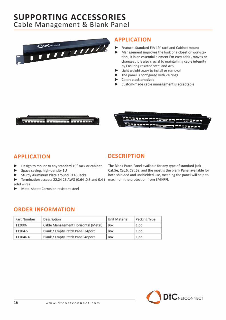
APPLICATIONThe Blank Patch Panel available for any type of standard jack Cat.5e, Cat.6, Cat.6a, and the most is the blank Panel available for both shielded and unshielded use, meaning the panel will help to maximum the protection from EMI/RFI.
Feature: Standard EIA 19” rack and Cabinet mount ►Management improves the look of a closet or worksta- ►tion , it is an essential element For easy adds , moves or changes , it is also crucial to maintaining cable integrity by Ensuring resisted steel and ABSLight weight ,easy to install or removal ►The panel is configured with 24 rings ►Color: black anodized ►Custom-made cable management is acceptable ►
Design to mount to any standard 19” rack or cabinet ►Space saving, high-density 1U ►Sturdy Aluminum Plate around RJ 45 Jacks ►Termination accepts 22,24 26 AWG (0.64 ,0.5 and 0.4 ) ►
solid wiresMetal sheet: Corrosion resistant steel ►
Cable Management & Blank Panel
ORDER INFORMATIONPart Number Description Unit Material Packing Type112006 Cable Management Horizontal (Metal) Box 1 pc11104-5 Blank / Empty Patch Panel 24port Box 1 pc111046-6 Blank / Empty Patch Panel 48port Box 1 pc
SUPPORTING ACCESSORIES
w w w . d t c n e t c o n n e c t . c o mDtCNETCONNECT
17
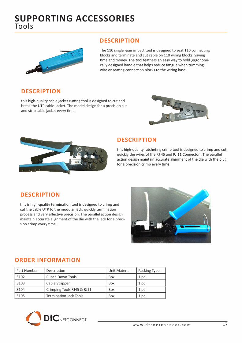
DESCRIPTION
DESCRIPTION
DESCRIPTION
DESCRIPTION
this high-quality cable jacket cutting tool is designed to cut and break the UTP cable Jacket. The model design for a precision cut and strip cable jacket every time.
The 110 single -pair impact tool is designed to seat 110 connectingblocks and terminate and cut cable on 110 wiring blocks. Saving time and money, The tool feathers an easy way to hold ,ergonomi-cally designed handle that helps reduce fatigue when trimming wire or seating connection blocks to the wiring base .
this high-quality ratcheting crimp tool is designed to crimp and cutquickly the wires of the RJ 45 and RJ 11 Connector . The parallel action design maintain accurate alignment of the die with the plug for a precision crimp every time.
this is high-quality termination tool is designed to crimp and cut the cable UTP to the modular jack, quickly termination process and very effective precision. The parallel action design maintain accurate alignment of the die with the jack for a preci-sion crimp every time.
Tools
ORDER INFORMATIONPart Number Description Unit Material Packing Type3102 Punch Down Tools Box 1 pc3103 Cable Stripper Box 1 pc3104 Crimping Tools RJ45 & RJ11 Box 1 pc3105 Termination Jack Tools Box 1 pc
FIBER OPTIC SOLUTION
w w w . d t c n e t c o n n e c t . c o mDtCNETCONNECT
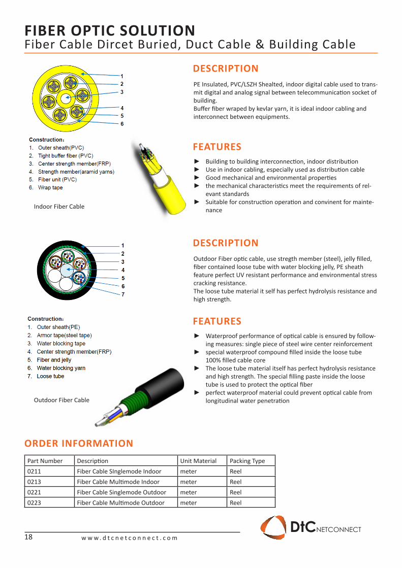
DESCRIPTION
DESCRIPTION
FEATURES
FEATURES
Building to building interconnection, indoor distribution ►Use in indoor cabling, especially used as distribution cable ►Good mechanical and environmental properties ►the mechanical characteristics meet the requirements of rel- ►evant standardsSuitable for construction operation and convinent for mainte- ►nance
Waterproof performance of optical cable is ensured by follow- ►ing measures: single piece of steel wire center reinforcementspecial waterproof compound filled inside the loose tube ►100% filled cable coreThe loose tube material itself has perfect hydrolysis resistance ►and high strength. The special filling paste inside the loose tube is used to protect the optical fiberperfect waterproof material could prevent optical cable from ►longitudinal water penetration
PE Insulated, PVC/LSZH Shealted, indoor digital cable used to trans-mit digital and analog signal between telecommunication socket of building.Buffer fiber wraped by kevlar yarn, it is ideal indoor cabling and interconnect between equipments.
Outdoor Fiber optic cable, use stregth member (steel), jelly filled, fiber contained loose tube with water blocking jelly, PE sheath feature perfect UV resistant performance and environmental stress cracking resistance.The loose tube material it self has perfect hydrolysis resistance and high strength.
Fiber Cable Dircet Buried, Duct Cable & Building Cable
ORDER INFORMATIONPart Number Description Unit Material Packing Type0211 Fiber Cable SInglemode Indoor meter Reel0213 Fiber Cable Multimode Indoor meter Reel0221 Fiber Cable Singlemode Outdoor meter Reel0223 Fiber Cable Multimode Outdoor meter Reel
Indoor Fiber Cable
Outdoor Fiber Cable
18
FIBER OPTIC SOLUTION
w w w . d t c n e t c o n n e c t . c o mDtCNETCONNECT
19
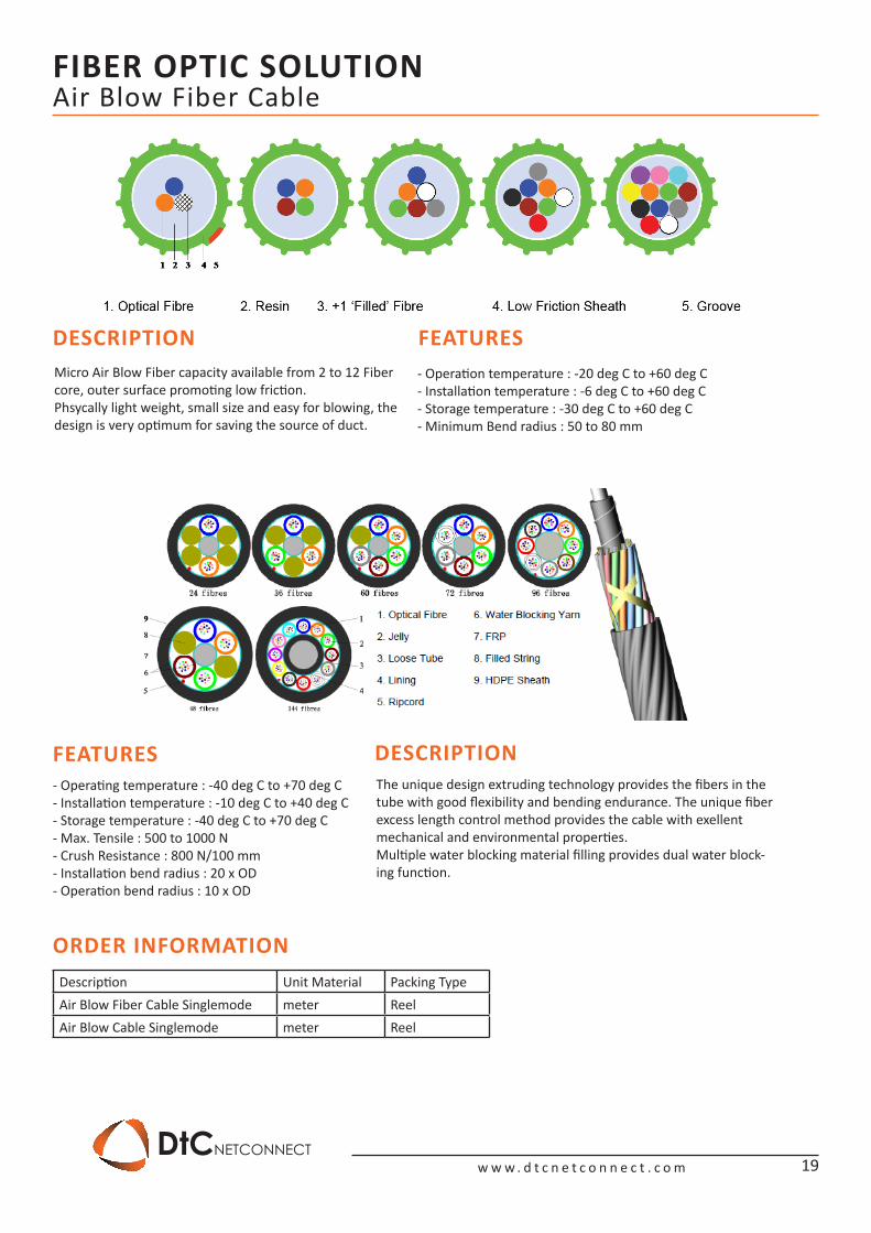
DESCRIPTION
DESCRIPTION
FEATURES
FEATURES
Micro Air Blow Fiber capacity available from 2 to 12 Fiber core, outer surface promoting low friction.Phsycally light weight, small size and easy for blowing, the design is very optimum for saving the source of duct.
The unique design extruding technology provides the fibers in the tube with good flexibility and bending endurance. The unique fiber excess length control method provides the cable with exellent mechanical and environmental properties.Multiple water blocking material filling provides dual water block-ing function.
Air Blow Fiber Cable
ORDER INFORMATIONDescription Unit Material Packing TypeAir Blow Fiber Cable Singlemode meter ReelAir Blow Cable Singlemode meter Reel
- Operation temperature : -20 deg C to +60 deg C- Installation temperature : -6 deg C to +60 deg C- Storage temperature : -30 deg C to +60 deg C- Minimum Bend radius : 50 to 80 mm
- Operating temperature : -40 deg C to +70 deg C- Installation temperature : -10 deg C to +40 deg C- Storage temperature : -40 deg C to +70 deg C- Max. Tensile : 500 to 1000 N- Crush Resistance : 800 N/100 mm- Installation bend radius : 20 x OD- Operation bend radius : 10 x OD
FIBER OPTIC SOLUTION
w w w . d t c n e t c o n n e c t . c o mDtCNETCONNECT
20
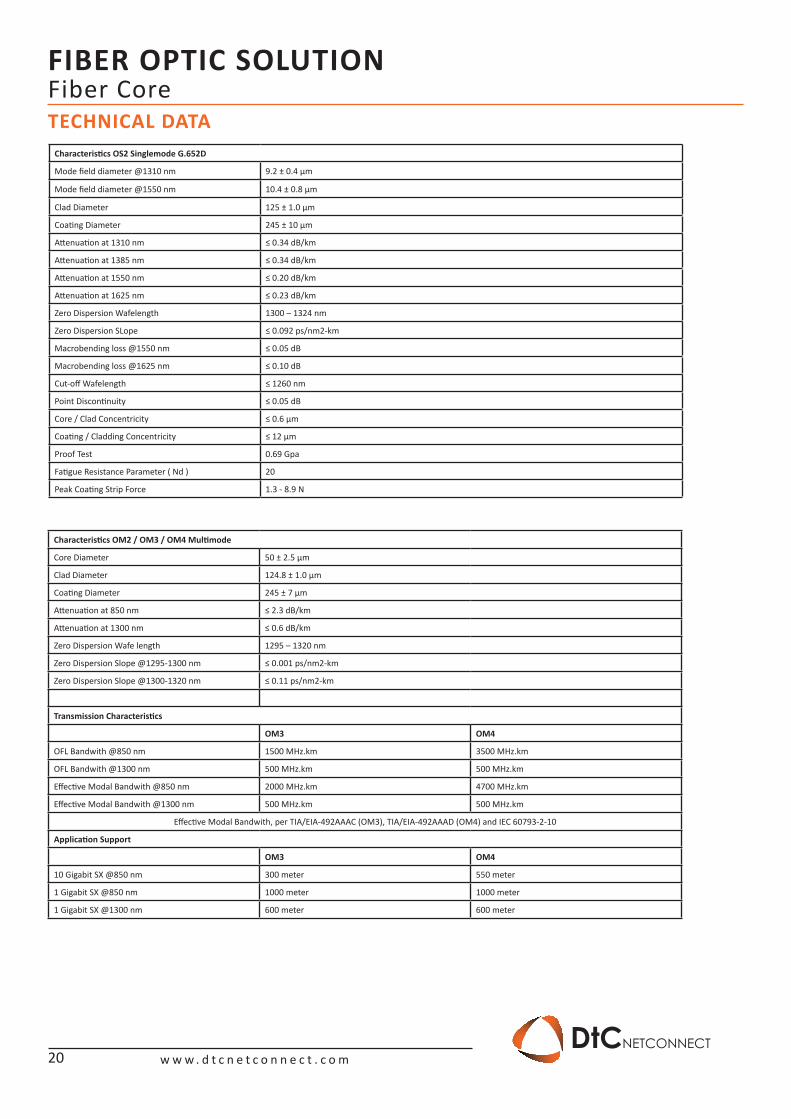
Fiber CoreTECHNICAL DATA
Characteristics OM2 / OM3 / OM4 Multimode
Core Diameter 50 ± 2.5 μm
Clad Diameter 124.8 ± 1.0 μm
Coating Diameter 245 ± 7 μm
Attenuation at 850 nm ≤ 2.3 dB/km
Attenuation at 1300 nm ≤ 0.6 dB/km
Zero Dispersion Wafe length 1295 – 1320 nm
Zero Dispersion Slope @1295-1300 nm ≤ 0.001 ps/nm2-km
Zero Dispersion Slope @1300-1320 nm ≤ 0.11 ps/nm2-km
Transmission Characteristics
OM3 OM4
OFL Bandwith @850 nm 1500 MHz.km 3500 MHz.km
OFL Bandwith @1300 nm 500 MHz.km 500 MHz.km
Effective Modal Bandwith @850 nm 2000 MHz.km 4700 MHz.km
Effective Modal Bandwith @1300 nm 500 MHz.km 500 MHz.km
Effective Modal Bandwith, per TIA/EIA-492AAAC (OM3), TIA/EIA-492AAAD (OM4) and IEC 60793-2-10
Application Support
OM3 OM4
10 Gigabit SX @850 nm 300 meter 550 meter
1 Gigabit SX @850 nm 1000 meter 1000 meter
1 Gigabit SX @1300 nm 600 meter 600 meter
Characteristics OS2 Singlemode G.652D
Mode field diameter @1310 nm 9.2 ± 0.4 μm
Mode field diameter @1550 nm 10.4 ± 0.8 μm
Clad Diameter 125 ± 1.0 μm
Coating Diameter 245 ± 10 μm
Attenuation at 1310 nm ≤ 0.34 dB/km
Attenuation at 1385 nm ≤ 0.34 dB/km
Attenuation at 1550 nm ≤ 0.20 dB/km
Attenuation at 1625 nm ≤ 0.23 dB/km
Zero Dispersion Wafelength 1300 – 1324 nm
Zero Dispersion SLope ≤ 0.092 ps/nm2-km
Macrobending loss @1550 nm ≤ 0.05 dB
Macrobending loss @1625 nm ≤ 0.10 dB
Cut-off Wafelength ≤ 1260 nm
Point Discontinuity ≤ 0.05 dB
Core / Clad Concentricity ≤ 0.6 μm
Coating / Cladding Concentricity ≤ 12 μm
Proof Test 0.69 Gpa
Fatigue Resistance Parameter ( Nd ) 20
Peak Coating Strip Force 1.3 - 8.9 N
FIBER OPTIC SOLUTION
w w w . d t c n e t c o n n e c t . c o mDtCNETCONNECT
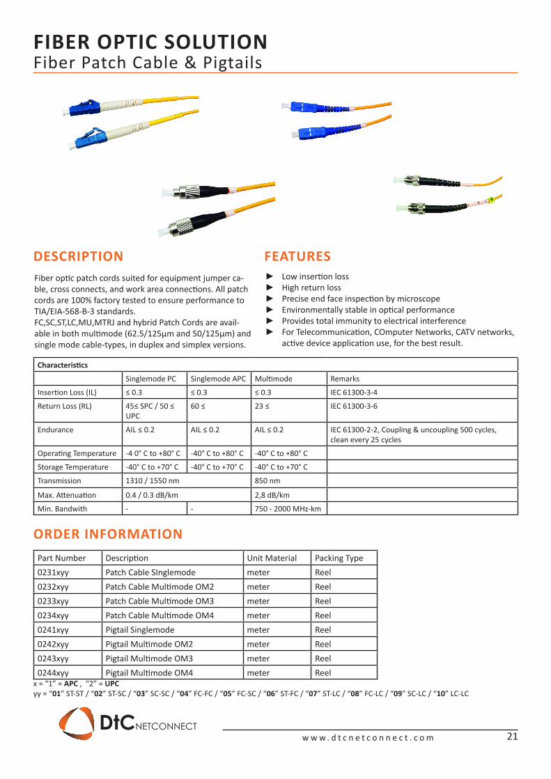
Fiber Patch Cable & Pigtails
DESCRIPTION FEATURESLow insertion loss ►High return loss ►Precise end face inspection by microscope ►Environmentally stable in optical performance ►Provides total immunity to electrical interference ►For Telecommunication, COmputer Networks, CATV networks, ►active device application use, for the best result.
Fiber optic patch cords suited for equipment jumper ca-ble, cross connects, and work area connections. All patch cords are 100% factory tested to ensure performance to TIA/EIA-568-B-3 standards.FC,SC,ST,LC,MU,MTRJ and hybrid Patch Cords are avail-able in both multimode (62.5/125μm and 50/125μm) and single mode cable-types, in duplex and simplex versions.
Characteristics
Singlemode PC Singlemode APC Multimode Remarks
Insertion Loss (IL) ≤ 0.3 ≤ 0.3 ≤ 0.3 IEC 61300-3-4
Return Loss (RL) 45≤ SPC / 50 ≤ UPC
60 ≤ 23 ≤ IEC 61300-3-6
Endurance AIL ≤ 0.2 AIL ≤ 0.2 AIL ≤ 0.2 IEC 61300-2-2, Coupling & uncoupling 500 cycles, clean every 25 cycles
Operating Temperature -4 0° C to +80° C -40° C to +80° C -40° C to +80° C
Storage Temperature -40° C to +70° C -40° C to +70° C -40° C to +70° C
Transmission 1310 / 1550 nm 850 nm
Max. Attenuation 0.4 / 0.3 dB/km 2,8 dB/km
Min. Bandwith - - 750 - 2000 MHz-km
ORDER INFORMATIONPart Number Description Unit Material Packing Type0231xyy Patch Cable SInglemode meter Reel0232xyy Patch Cable Multimode OM2 meter Reel0233xyy Patch Cable Multimode OM3 meter Reel0234xyy Patch Cable Multimode OM4 meter Reel0241xyy Pigtail Singlemode meter Reel0242xyy Pigtail Multimode OM2 meter Reel0243xyy Pigtail Multimode OM3 meter Reel0244xyy Pigtail Multimode OM4 meter Reel
x = “1” = APC , “2” = UPCyy = “01” ST-ST / “02” ST-SC / “03” SC-SC / “04” FC-FC / “05” FC-SC / “06” ST-FC / “07” ST-LC / “08” FC-LC / “09” SC-LC / “10” LC-LC
21
FIBER OPTIC SOLUTION
w w w . d t c n e t c o n n e c t . c o mDtCNETCONNECT
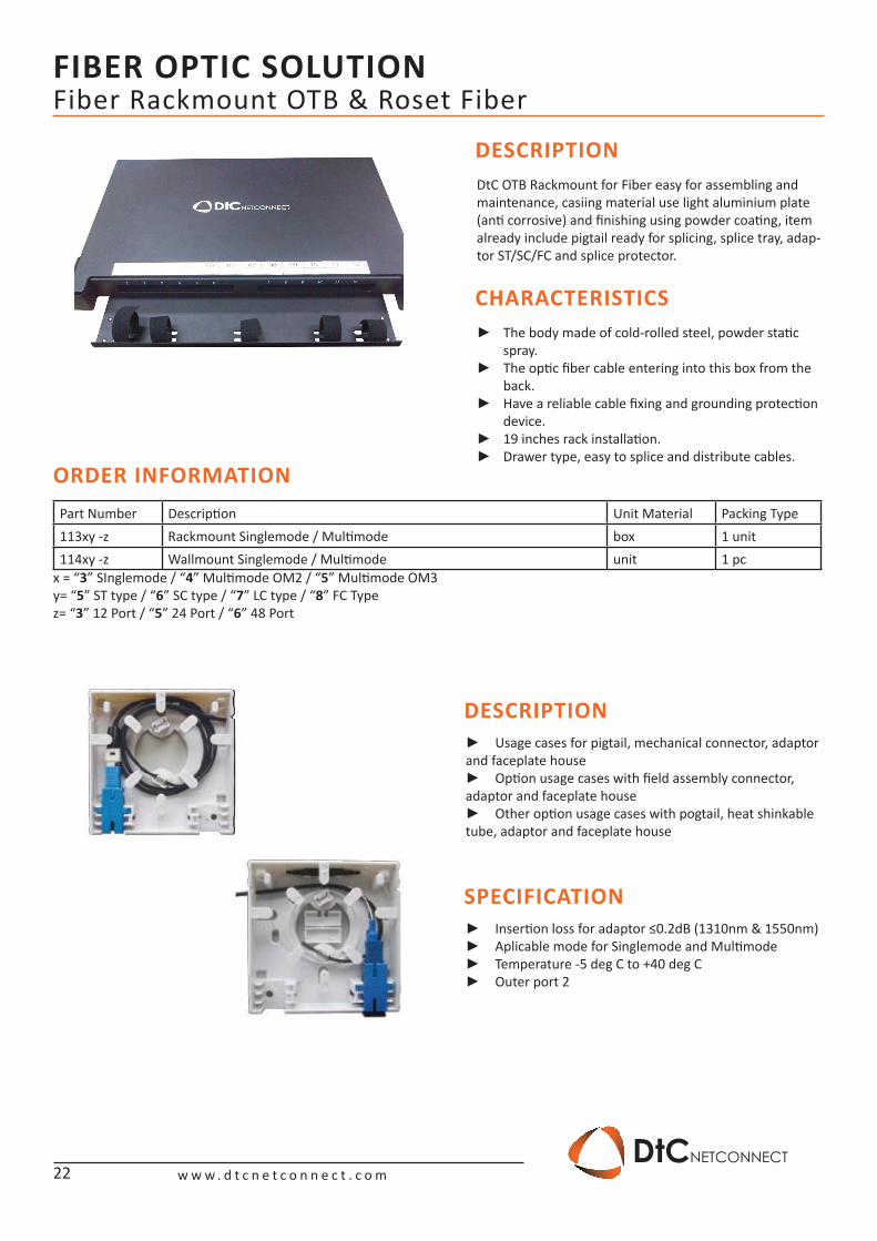
Fiber Rackmount OTB & Roset Fiber
DESCRIPTION
CHARACTERISTICS
DtC OTB Rackmount for Fiber easy for assembling and maintenance, casiing material use light aluminium plate (anti corrosive) and finishing using powder coating, item already include pigtail ready for splicing, splice tray, adap-tor ST/SC/FC and splice protector.
The body made of cold-rolled steel, powder static ►spray.The optic fiber cable entering into this box from the ►back.Have a reliable cable fixing and grounding protection ►device. 19 inches rack installation. ►Drawer type, easy to splice and distribute cables. ►
ORDER INFORMATIONPart Number Description Unit Material Packing Type113xy -z Rackmount Singlemode / Multimode box 1 unit114xy -z Wallmount Singlemode / Multimode unit 1 pc
x = “3” SInglemode / “4” Multimode OM2 / “5” Multimode OM3y= “5” ST type / “6” SC type / “7” LC type / “8” FC Typez= “3” 12 Port / “5” 24 Port / “6” 48 Port
22
DESCRIPTION
SPECIFICATION
Usage cases for pigtail, mechanical connector, adaptor ►and faceplate house
Option usage cases with field assembly connector, ►adaptor and faceplate house
Other option usage cases with pogtail, heat shinkable ►tube, adaptor and faceplate house
Insertion loss for adaptor ≤0.2dB (1310nm & 1550nm) ►Aplicable mode for Singlemode and Multimode ►Temperature -5 deg C to +40 deg C ►Outer port 2 ►
FIBER OPTIC SOLUTION
w w w . d t c n e t c o n n e c t . c o mDtCNETCONNECT
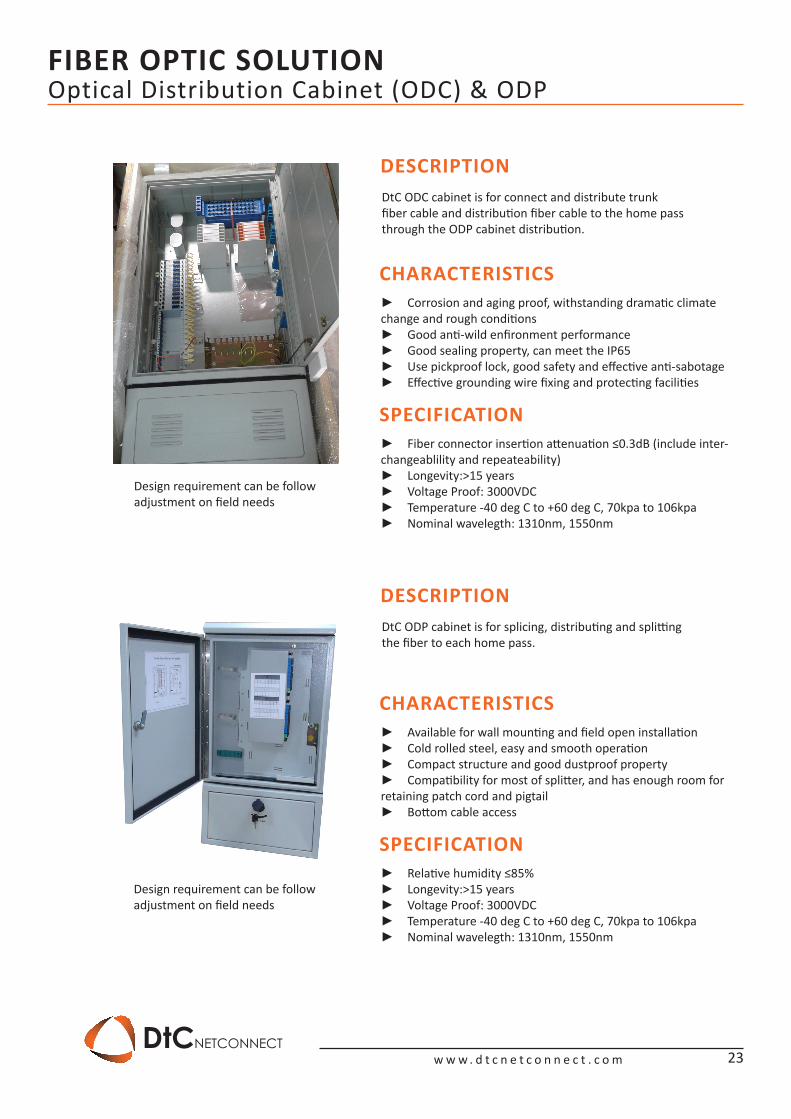
Optical Distribution Cabinet (ODC) & ODP
DESCRIPTION
DESCRIPTION
DtC ODC cabinet is for connect and distribute trunk fiber cable and distribution fiber cable to the home pass through the ODP cabinet distribution.
DtC ODP cabinet is for splicing, distributing and splitting the fiber to each home pass.
CHARACTERISTICS
CHARACTERISTICS
SPECIFICATION
SPECIFICATION
Corrosion and aging proof, withstanding dramatic climate ►change and rough conditions
Good anti-wild enfironment performance ►Good sealing property, can meet the IP65 ►Use pickproof lock, good safety and effective anti-sabotage ►Effective grounding wire fixing and protecting facilities ►
Available for wall mounting and field open installation ►Cold rolled steel, easy and smooth operation ►Compact structure and good dustproof property ►Compatibility for most of splitter, and has enough room for ►
retaining patch cord and pigtailBottom cable access ►
Fiber connector insertion attenuation ≤0.3dB (include inter- ►changeablility and repeateability)
Longevity:>15 years ►Voltage Proof: 3000VDC ►Temperature -40 deg C to +60 deg C, 70kpa to 106kpa ►Nominal wavelegth: 1310nm, 1550nm ►
Relative humidity ≤85% ►Longevity:>15 years ►Voltage Proof: 3000VDC ►Temperature -40 deg C to +60 deg C, 70kpa to 106kpa ►Nominal wavelegth: 1310nm, 1550nm ►
Design requirement can be follow adjustment on field needs
Design requirement can be follow adjustment on field needs
23
FIBER OPTIC SOLUTION
w w w . d t c n e t c o n n e c t . c o mDtCNETCONNECT
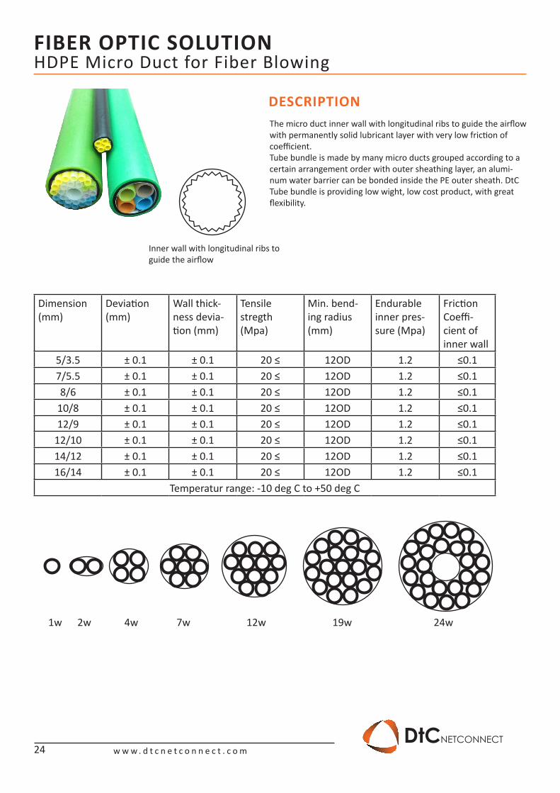
HDPE Micro Duct for Fiber Blowing
Inner wall with longitudinal ribs to guide the airflow
DESCRIPTIONThe micro duct inner wall with longitudinal ribs to guide the airflow with permanently solid lubricant layer with very low friction of coefficient.Tube bundle is made by many micro ducts grouped according to a certain arrangement order with outer sheathing layer, an alumi-num water barrier can be bonded inside the PE outer sheath. DtC Tube bundle is providing low wight, low cost product, with great flexibility.
Dimension (mm)
Deviation (mm)
Wall thick-ness devia-tion (mm)
Tensile stregth (Mpa)
Min. bend-ing radius (mm)
Endurable inner pres-sure (Mpa)
Friction Coeffi-cient of inner wall
5/3.5 ± 0.1 ± 0.1 20 ≤ 12OD 1.2 ≤0.17/5.5 ± 0.1 ± 0.1 20 ≤ 12OD 1.2 ≤0.18/6 ± 0.1 ± 0.1 20 ≤ 12OD 1.2 ≤0.1
10/8 ± 0.1 ± 0.1 20 ≤ 12OD 1.2 ≤0.112/9 ± 0.1 ± 0.1 20 ≤ 12OD 1.2 ≤0.1
12/10 ± 0.1 ± 0.1 20 ≤ 12OD 1.2 ≤0.114/12 ± 0.1 ± 0.1 20 ≤ 12OD 1.2 ≤0.116/14 ± 0.1 ± 0.1 20 ≤ 12OD 1.2 ≤0.1
Temperatur range: -10 deg C to +50 deg C
1w 2w 4w 7w 12w 19w 24w
24
FIBER OPTIC SOLUTION
w w w . d t c n e t c o n n e c t . c o mDtCNETCONNECT
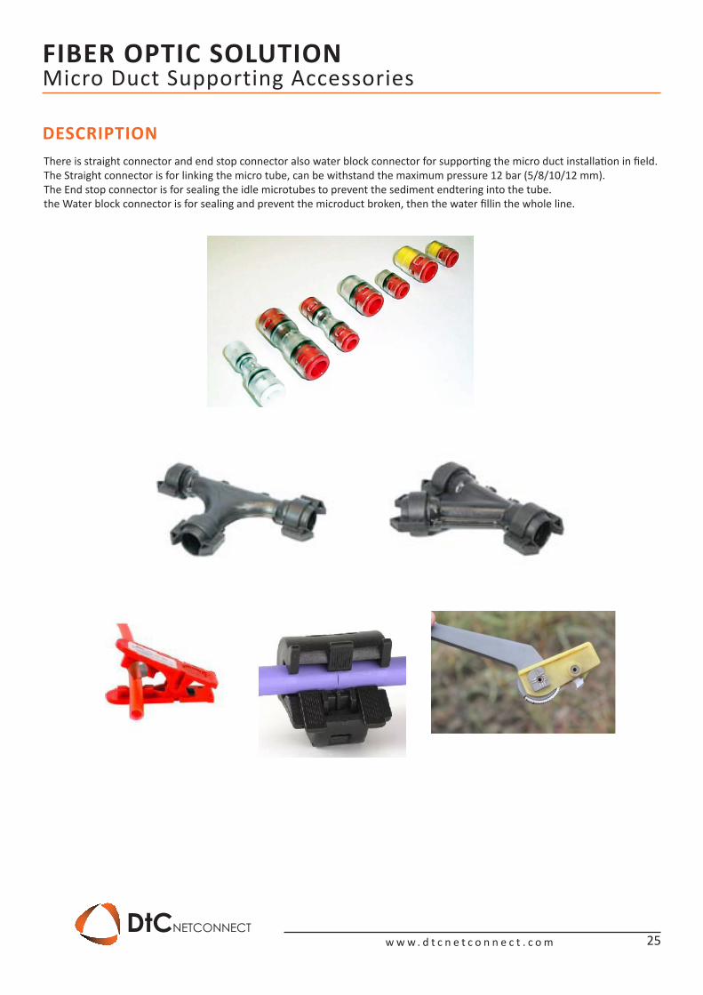
Micro Duct Supporting Accessories
DESCRIPTIONThere is straight connector and end stop connector also water block connector for supporting the micro duct installation in field.The Straight connector is for linking the micro tube, can be withstand the maximum pressure 12 bar (5/8/10/12 mm).The End stop connector is for sealing the idle microtubes to prevent the sediment endtering into the tube.the Water block connector is for sealing and prevent the microduct broken, then the water fillin the whole line.
25
CABINET SOLUTION
w w w . d t c n e t c o n n e c t . c o mDtCNETCONNECT
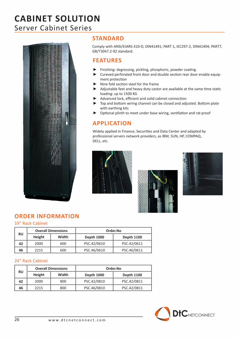
Server Cabinet SeriesSTANDARD
FEATURES
APPLICATION
Comply with ANSI/EIARS-310-D, DIN41491; PART 1, IEC297-2, DIN41494; PART7, GB/T3047.2-92 standard.
Widely applied in Finance, Securities and Data Center and adapted by professional servers network providers, as IBM, SUN, HP, COMPAQ,DELL, etc.
Finishing: degressing, pickling, phosphoric, powder coating. ►Cureved perforated front door and double section rear door enable equip- ►ment protectionNine fold section steel for the frame ►Adjustable feet and heavy duty castor are available at the same time static ►loading: up to 1500 KGAdvanced lock, efficient and solid cabinet connection ►Top and bottom wiring channel can be closed and adjusted. Bottom plate ►with earthing kitsOptional plinth to meet under base wiring, ventilation and rat-proof ►
ORDER INFORMATION
RUOverall Dimensions Order.No
Height Width Depth 1000 Depth 1100
42 2000 600 PSC.42/0610 PSC.42/0611
46 2215 600 PSC.46/0610 PSC.46/0611
RUOverall Dimensions Order.No
Height Width Depth 1000 Depth 1100
42 2000 800 PSC.42/0810 PSC.42/0811
46 2215 800 PSC.46/0810 PSC.42/0811
19” Rack Cabinet
24” Rack Cabinet
26
CABINET SOLUTION
w w w . d t c n e t c o n n e c t . c o mDtCNETCONNECT
Server Cabinet Series
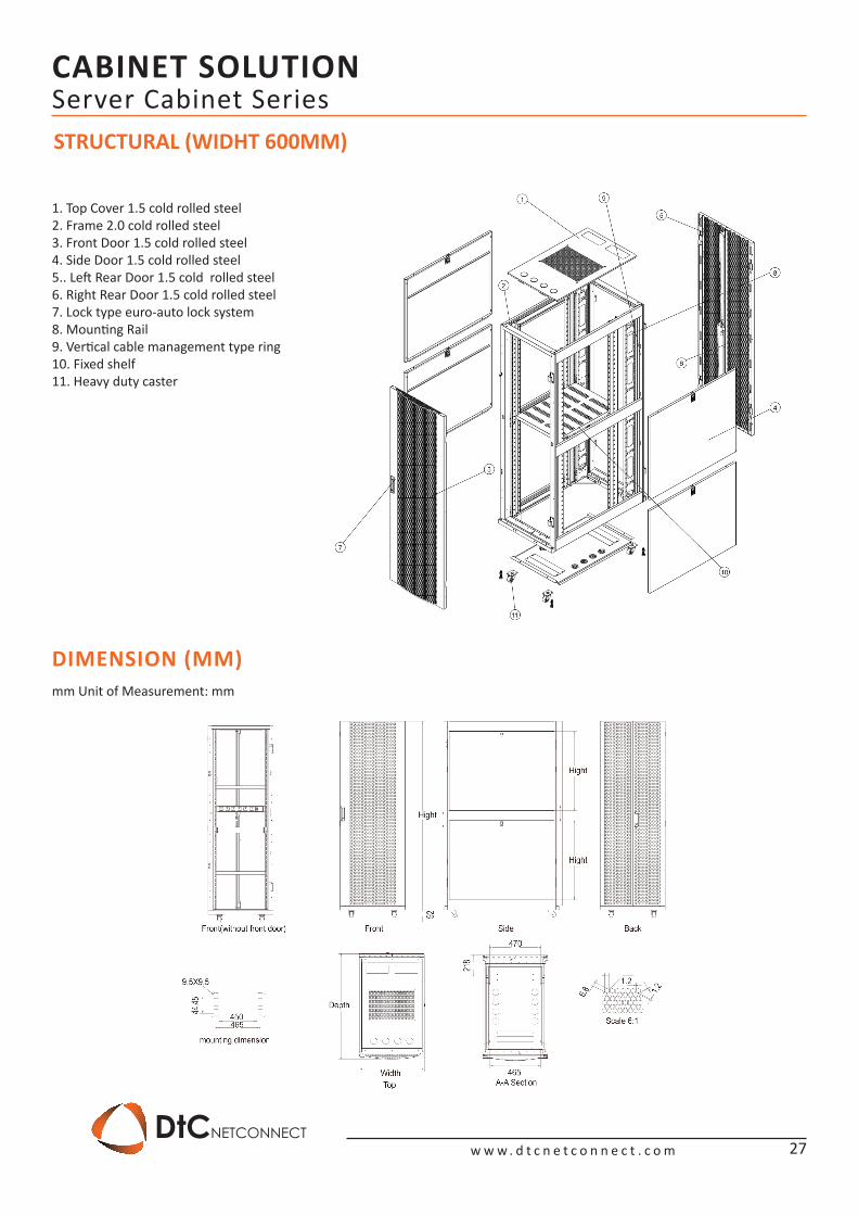
1. Top Cover 1.5 cold rolled steel2. Frame 2.0 cold rolled steel3. Front Door 1.5 cold rolled steel4. Side Door 1.5 cold rolled steel5.. Left Rear Door 1.5 cold rolled steel6. Right Rear Door 1.5 cold rolled steel7. Lock type euro-auto lock system8. Mounting Rail9. Vertical cable management type ring10. Fixed shelf 11. Heavy duty caster
STRUCTURAL (WIDHT 600MM)
mm Unit of Measurement: mm
DIMENSION (MM)
27
CABINET SOLUTION
w w w . d t c n e t c o n n e c t . c o mDtCNETCONNECT
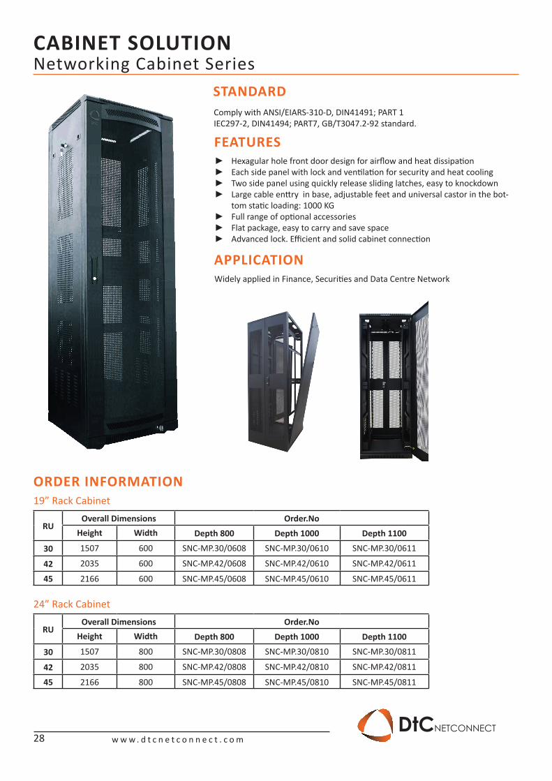
Networking Cabinet Series
Comply with ANSI/EIARS-310-D, DIN41491; PART 1IEC297-2, DIN41494; PART7, GB/T3047.2-92 standard.
Widely applied in Finance, Securities and Data Centre Network
STANDARD
FEATURES
APPLICATION
Hexagular hole front door design for airflow and heat dissipation ►Each side panel with lock and ventilation for security and heat cooling ►Two side panel using quickly release sliding latches, easy to knockdown ►Large cable enttry in base, adjustable feet and universal castor in the bot- ►tom static loading: 1000 KGFull range of optional accessories ►Flat package, easy to carry and save space ►Advanced lock. Efficient and solid cabinet connection ►
ORDER INFORMATION
RUOverall Dimensions Order.No
Height Width Depth 800 Depth 1000 Depth 1100
30 1507 600 SNC-MP.30/0608 SNC-MP.30/0610 SNC-MP.30/0611
42 2035 600 SNC-MP.42/0608 SNC-MP.42/0610 SNC-MP.42/0611
45 2166 600 SNC-MP.45/0608 SNC-MP.45/0610 SNC-MP.45/0611
RUOverall Dimensions Order.No
Height Width Depth 800 Depth 1000 Depth 1100
30 1507 800 SNC-MP.30/0808 SNC-MP.30/0810 SNC-MP.30/0811
42 2035 800 SNC-MP.42/0808 SNC-MP.42/0810 SNC-MP.42/0811
45 2166 800 SNC-MP.45/0808 SNC-MP.45/0810 SNC-MP.45/0811
19” Rack Cabinet
24” Rack Cabinet
28
CABINET SOLUTION
w w w . d t c n e t c o n n e c t . c o mDtCNETCONNECT
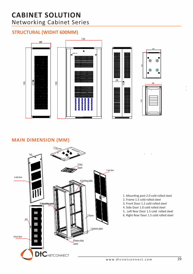
Networking Cabinet SeriesSTRUCTURAL (WIDHT 600MM)
MAIN DIMENSION (MM)
1. Mounting post 2.0 cold rolled steel2. Frame 1.5 cold rolled steel3. Front Door 1.2 cold rolled steel4. Side Door 1.0 cold rolled steel5.. Left Rear Door 1.5 cold rolled steel6. Right Rear Door 1.5 cold rolled steel
3 top cover
1 bottom plate
2 frame
4 jointing plate
5 mounting post
9.heavy duty castor
10.fan panel
5 mounting post
lock
lock
8 front door
6 side door
lock
7 rear door
600
1959
600
plastic lock
1100
1959
299
1100
600
1100
600
29
CABINET SOLUTION
w w w . d t c n e t c o n n e c t . c o mDtCNETCONNECT
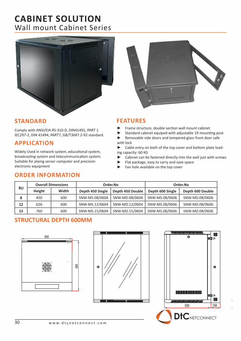
Wall mount Cabinet Series
STANDARDComply with ANSI/EIA RS-310-D, DIN41491; PART 1IEC297-2, DIN 41494; PART7, GB/T3047.2-92 standard.
FEATURES
APPLICATIONWidely Used in network system, educational system, broadcasting system and telecommunication system. Suitable for plaing server computer and precision electronic equipment
Frame structure, double section wall mount cabinet ►Standard cabinet equiped with adjustable 19 mounting post ►Removable side doors and tempered glass front door safe ►
with lockCable entry on both of the top cover and bottom plate load- ►
ing capacity: 60 KGCabinet can be fastened directly into the wall just with screws ►Flat package, easy to carry and save space ►Fan hole available on the top cover ►
STRUCTURAL DEPTH 600MM
ORDER INFORMATION
RUOverall Dimensions Order.No Order.No
Height Width Depth 450 Single Depth 450 Double Depth 600 Single Depth 600 Double
8 450 600 SNW-MS.08/0604 SNW-MD.08/0604 SNW-MS.08/0606 SNW-MD.08/0606
12 626 600 SNW-MS.12/0604 SNW-MD.12/0604 SNW-MS.08/0606 SNW-MD.08/0606
15 760 600 SNW-MS.15/0604 SNW-MD.15/0604 SNW-MS.08/0606 SNW-MD.08/0606
500 100
600
600
30
CABINET SOLUTION
w w w . d t c n e t c o n n e c t . c o mDtCNETCONNECT
500 100
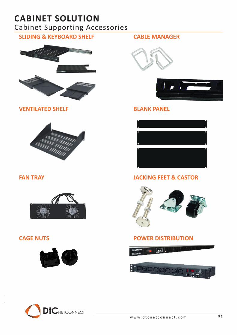
Cabinet Supporting Accessories SLIDING & KEYBOARD SHELF
VENTILATED SHELF
FAN TRAY
CAGE NUTS
BLANK PANEL
JACKING FEET & CASTOR
POWER DISTRIBUTION
CABLE MANAGER
31
INDEX
w w w . d t c n e t c o n n e c t . c o mDtCNETCONNECT
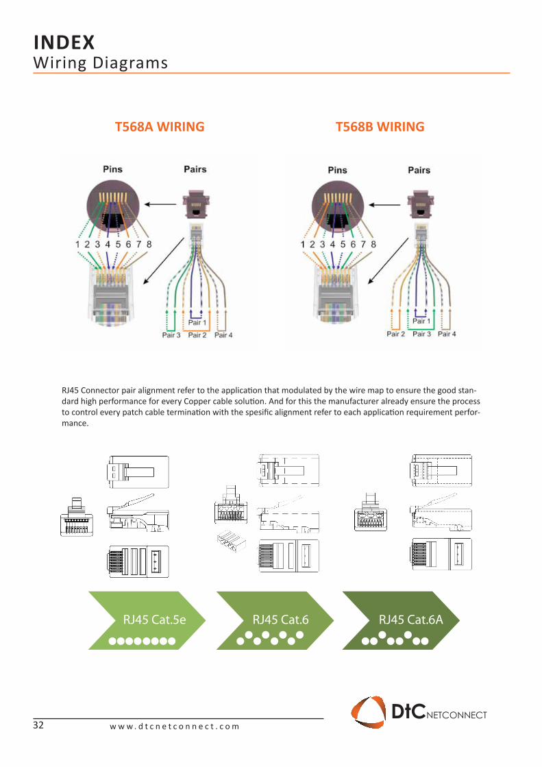
Wiring Diagrams
T568A WIRING T568B WIRING
RJ45 Cat.5e RJ45 Cat.6 RJ45 Cat.6A
RJ45 Connector pair alignment refer to the application that modulated by the wire map to ensure the good stan-dard high performance for every Copper cable solution. And for this the manufacturer already ensure the process to control every patch cable termination with the spesific alignment refer to each application requirement perfor-mance.
32
We Appreciate Your Trust In Our Services, Because You Are Valuable For Us...
Connecting is what we do concern, we do value our customer and our partner needs in the networking business since 1994, and today we want to bring more close the better services along with the better stable solution to all of Indonesia valuable customer. With the worldwide standardization we could provide the 25 year warranty replacing for covering the customer infrastructure networking solution, we do commitment to the valuable cus-tomer to do “the never-stop development” for the product range.
Your One Stop Solution Data Networking Only at;
w w w . d t c n e t c o n n e c t . c o m
DtCNETCONNECT
RoHSCompliance

PT Adhitya Mandiri Pratama - Since 1994 - Jakarta Indonesia | All right reserved © 2014
w w w . d t c n e t c o n n e c t . c o m
Put our product to the test,
contact us for a free consultation today. DtCNETCONNECT
Recommended