SHELL OFFSHORE INC.
3601 C Street, Suite 1000 Anchorage, AK 99503
DRILLING ICE MANAGEMENT PLAN Chukchi Sea, Alaska
Submitted to:
U. S. Department of the Interior Bureau of Safety and Environmental Enforcement Alaska Outer Continental Shelf Region
Submitted by:
Shell Gulf of Mexico Inc.
Pri
nte
d c
op
ies o
f th
is d
oc
um
ent
are
UN
CO
NT
RO
LLE
D.
De
str
oy
(R
EC
YC
LE
) a
fte
r u
se
.
Drilling Ice Management Plan Chukchi Sea, Alaska
Shell Gulf of Mexico Inc. 2 July, 2014
DRILLING ICE MANAGEMENT PLAN
Approval: Approved for the Alaska Asset
Effective This document is effective per the latest approval date above.
Expires In force until revised and/or superseded.
Custodian Alaska Marine Manager
Author Ice Management Lead (July, 2014 Revision)
Reviewers Principal Arctic Marine Facilities Advisor
VP Alaska BOM
VP Arctic HSSE
VP Alaska Operations
Alaska Maritime Assurance Manager
Alaska Wells Operations Manager
Arctic Execution Manager
Offshore Regulatory Team Lead
Shell Exploration & Production Company Approved Date
VP Wells Arctic & Industry Regulatory Affairs Signature on file 7/9/2014
Pri
nte
d c
op
ies o
f th
is d
oc
um
ent
are
UN
CO
NT
RO
LLE
D.
De
str
oy
(R
EC
YC
LE
) a
fte
r u
se
.
Drilling Ice Management Plan Chukchi Sea, Alaska
Shell Gulf of Mexico Inc. 3 July, 2014
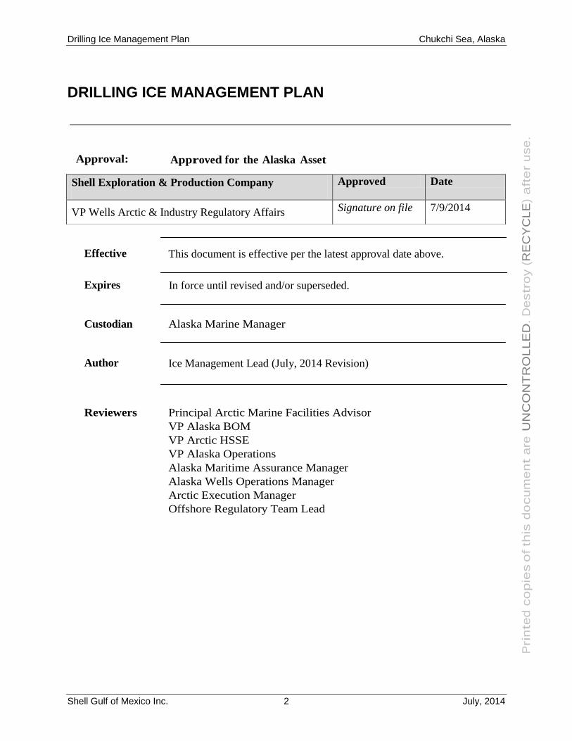
Topic Define the method and system to ensure the safe departure of the drilling
unit from the well site due to incursion of hazardous sea ice.
Purpose/Scope The purpose of this Drilling Ice Management Plan is to provide a
consistent, safe method for full compliance with the Alaska Venture
operating / permitting requirements with regard to the Critical Operation
Curtailment Plan which encompasses the Drilling Ice Management Plan.
Applies to This document applies to all Shell employees and contractors conducting
operations on behalf of the Shell Alaska Venture.
Primary
Responsibility
Alaska Venture Maritime & Logistics supervision shall be responsible for
assuring that this plan is provided and that operators are instructed to use
this procedure prior to all marine drilling operations in Arctic waters
where sea ice incursion is expected.
Drilling Ice Management Plan Chukchi Sea, Alaska
Shell Gulf of Mexico Inc. 4 July, 2014
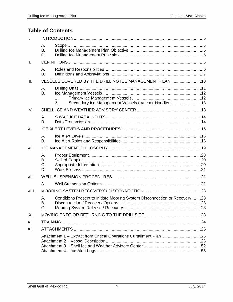
Table of Contents
I. INTRODUCTION ............................................................................................................. 5
A. Scope .................................................................................................................. 5 B. Drilling Ice Management Plan Objective ............................................................... 6 C. Drilling Ice Management Principles ...................................................................... 6
II. DEFINITIONS .................................................................................................................. 6
A. Roles and Responsibilities ................................................................................... 6 B. Definitions and Abbreviations ............................................................................... 7
III. VESSELS COVERED BY THE DRILLING ICE MANAGEMENT PLAN ......................... 10
A. Drilling Units ....................................................................................................... 11 B. Ice Management Vessels ................................................................................... 12
1. Primary Ice Management Vessels .......................................................... 12 2. Secondary Ice Management Vessels / Anchor Handlers ........................ 13
IV. SHELL ICE AND WEATHER ADVISORY CENTER ...................................................... 13
A. SIWAC ICE DATA INPUTS ................................................................................ 14 B. Data Transmission ............................................................................................. 14
V. ICE ALERT LEVELS AND PROCEDURES ................................................................... 16
A. Ice Alert Levels .................................................................................................. 16 B. Ice Alert Roles and Responsibilities ................................................................... 16
VI. ICE MANAGEMENT PHILOSOPHY .............................................................................. 19
A. Proper Equipment .............................................................................................. 20 B. Skilled People .................................................................................................... 20 C. Appropriate Information...................................................................................... 20 D. Work Process .................................................................................................... 21
VII. WELL SUSPENSION PROCEDURES .......................................................................... 21
A. Well Suspension Options ................................................................................... 21
VIII. MOORING SYSTEM RECOVERY / DISCONNECTION ................................................ 23
A. Conditions Present to Initiate Mooring System Disconnection or Recovery ........ 23 B. Disconnection / Recovery Options ..................................................................... 23 C. Mooring System Release / Recovery ................................................................. 23
IX. MOVING ONTO OR RETURNING TO THE DRILLSITE ............................................... 23
X. TRAINING ..................................................................................................................... 24
XI. ATTACHMENTS ........................................................................................................... 25
Attachment 1 – Extract from Critical Operations Curtailment Plan ................................. 25 Attachment 2 – Vessel Description ................................................................................ 26 Attachment 3 – Shell Ice and Weather Advisory Center ................................................ 52 Attachment 4 – Ice Alert Logs ........................................................................................ 53
Drilling Ice Management Plan Chukchi Sea, Alaska
Shell Gulf of Mexico Inc. 5 July, 2014
I. INTRODUCTION
A. Scope
A Critical Operations Curtailment Plan (COCP) is in place for the Shell Gulf of Mexico Inc.
(Shell) Chukchi Sea Exploration Drilling Program. As part of the COCP, this Drilling Ice
Management Plan (DIMP) has been developed. The description of notification of curtailment (an
excerpt from the COCP) is presented in Attachment 1.
Drilling operations in the Chukchi Sea will be conducted using two drilling units operating
simultaneously. The drilling units are the “Noble Discoverer” and the “Polar Pioneer”. Both
drilling units will operate according to this Drilling Ice Management Plan
The DIMP addresses the following activities:
Vessels
Shell Ice and Weather Advisory Center (SIWAC), located in Anchorage
Ice Alerts and Procedures
Ice Management Philosophy
Well Suspension Contingencies
Mooring System Recovery and Release
Moving onto or returning to the Drill Site
Training
The DIMP:
Defines Roles and Responsibilities
Establishes Alert Levels
Establishes Responses to Alert Levels
The DIMP facilitates appropriate decision-making and responses to the threat of hazardous ice
and procedures set forth in the DIMP to prevent damage or harm to personnel, assets, or the
environment.
Nothing in this document takes away the authority and accountability of the Master(s) of the
vessels for the safety of their personnel and vessels, and for protection of the environment.
This plan is not a substitute for good judgment.
Guidance Note: This document is not intended to contain detailed procedures. Detailed
procedures are contained within the vessel-specific operating manuals and the Shell Ice
Management Guidance and Procedures manual.
Drilling Ice Management Plan Chukchi Sea, Alaska
Shell Gulf of Mexico Inc. 6 July, 2014
B. Drilling Ice Management Plan Objective
The objectives of the DIMP are to detect and monitor sea ice conditions, identify
hazardous ice and determine manageability as per the DIMP and Alert System in
order to ensure risk to personnel, drilling units, vessels or wells is reduced to ALARP.
The Ice Alert System is central to the function of the DIMP. It is based on five
progressive alert levels. Each level defines operational status, roles, responsibilities
and actions required.
C. Drilling Ice Management Principles
Early detection of ice features
Assessment of the ice regime
Identification of Hazardous Ice
Assessment of Ice Management Vessel (IMV) capabilities to manage ice
Calculation and monitoring of Hazardous Ice arrival at drill site, Hazard Time (HT)
Continuous assessment of time required to secure the well, Secure Time (ST)
Continuous assessment of time required to move rig off location, Move Time (MT)
Alert Level assignment which triggers the appropriate responses
Development of ice management strategy
Monitoring effectiveness of strategy
Predefined roles and responsibilities
II. DEFINITIONS
A. Roles and Responsibilities
Responsibilities have been defined for key on-site personnel in Section V. In addition to the
defined personnel the following onshore positions have a role to play in the DIMP.
Wells Operations Manager
Shell’s Wells Operations Manager is the senior Shell shore-based manager responsible
for all Shell well operations offshore Alaska.
Wells Operations Team Leads
The Wells Operations Team Leads are responsible for Shell well operations at a specific
well site. There is a Wells Operations Team Lead ashore for each drilling location who
will update the OEMT on Ice Alert Status or changes to the Ice Alert Level.
Drilling Ice Management Plan Chukchi Sea, Alaska
Shell Gulf of Mexico Inc. 7 July, 2014
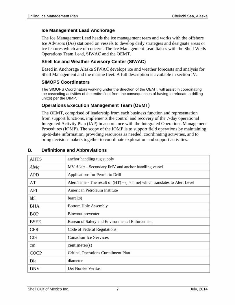
Ice Management Lead Anchorage
The Ice Management Lead heads the ice management team and works with the offshore
Ice Advisors (IAs) stationed on vessels to develop daily strategies and designate areas or
ice features which are of concern. The Ice Management Lead liaises with the Shell Wells
Operations Team Lead, SIWAC and the OEMT.
Shell Ice and Weather Advisory Center (SIWAC)
Based in Anchorage Alaska SIWAC develops ice and weather forecasts and analysis for
Shell Management and the marine fleet. A full description is available in section IV.
SIMOPS Coordinators
The SIMOPS Coordinators working under the direction of the OEMT, will assist in coordinating the cascading activities of the entire fleet from the consequences of having to relocate a drilling unit(s) per the DIMP.
Operations Execution Management Team (OEMT)
The OEMT, comprised of leadership from each business function and representation
from support functions, implements the control and recovery of the 7-day operational
Integrated Activity Plan (IAP) in accordance with the Integrated Operations Management
Procedures (IOMP). The scope of the IOMP is to support field operations by maintaining
up-to-date information, providing resources as needed, coordinating activities, and to
bring decision-makers together to coordinate exploration and support activities.
B. Definitions and Abbreviations
AHTS anchor handling tug supply
Aiviq MV Aiviq – Secondary IMV and anchor handling vessel
APD Applications for Permit to Drill
AT Alert Time - The result of (HT) – (T-Time) which translates to Alert Level
API American Petroleum Institute
bbl barrel(s)
BHA Bottom Hole Assembly
BOP Blowout preventer
BSEE Bureau of Safety and Environmental Enforcement
CFR Code of Federal Regulations
CIS Canadian Ice Services
cm centimeter(s)
COCP Critical Operations Curtailment Plan
Dia. diameter
DNV Det Norske Veritas
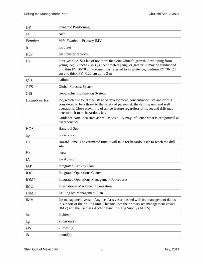
Drilling Ice Management Plan Chukchi Sea, Alaska
Shell Gulf of Mexico Inc. 8 July, 2014
DP Dynamic Positioning
ea each
Fennica M/V Fennica – Primary IMV
ft foot/feet
FTP file transfer protocol
FY First-year ice. Sea ice of not more than one winter’s growth, developing from
young ice; 12 inches (in.) (30 centimeters [cm]) or greater. It may be subdivided
into thin FY 30-70 cm – sometimes referred to as white ice, medium FY 70-120
cm and thick FY >120 cm up to 2 m.
gals. gallons
GFS Global Forecast System
GIS Geographic Information System
Hazardous Ice Ice, which due to its size, stage of development, concentration, set and drift is
considered to be a threat to the safety of personnel, the drilling unit and well
operations. Close proximity of an ice feature regardless of its set and drift may
determine it to be hazardous ice.
Guidance Note: Sea state as well as visibility may influence what is categorized as
hazardous ice.
HOS Hang-off Sub
hp horsepower
HT Hazard Time. The estimated time it will take for hazardous ice to reach the drill
site.
Hz hertz
IA Ice Advisor
IAP Integrated Activity Plan
IOC Integrated Operations Center
IOMP Integrated Operations Management Procedures
IMO International Maritime Organization
DIMP Drilling Ice Management Plan
IMV Ice management vessel. Any ice class vessel tasked with ice management duties
in support of the drilling unit. This includes the primary ice management vessel
(IMV) and the ice class Anchor Handling Tug Supply (AHTS)
in. Inch(es)
kg kilogram(s)
kW kilowatt(s)
lb pound(s)
Drilling Ice Management Plan Chukchi Sea, Alaska
Shell Gulf of Mexico Inc. 9 July, 2014
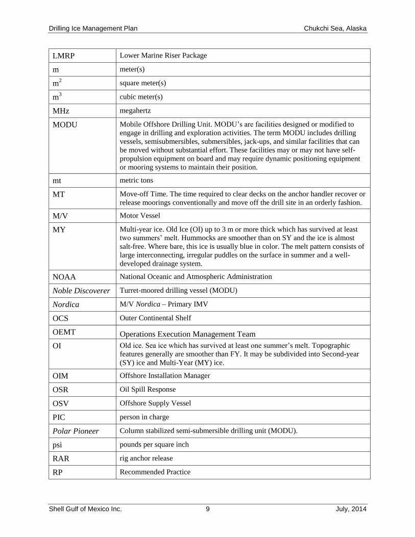
LMRP Lower Marine Riser Package
m meter(s)
m2 square meter(s)
m3 cubic meter(s)
MHz megahertz
MODU Mobile Offshore Drilling Unit. MODU’s are facilities designed or modified to
engage in drilling and exploration activities. The term MODU includes drilling
vessels, semisubmersibles, submersibles, jack-ups, and similar facilities that can
be moved without substantial effort. These facilities may or may not have self-
propulsion equipment on board and may require dynamic positioning equipment
or mooring systems to maintain their position.
mt metric tons
MT Move-off Time. The time required to clear decks on the anchor handler recover or
release moorings conventionally and move off the drill site in an orderly fashion.
M/V Motor Vessel
MY Multi-year ice. Old Ice (OI) up to 3 m or more thick which has survived at least
two summers’ melt. Hummocks are smoother than on SY and the ice is almost
salt-free. Where bare, this ice is usually blue in color. The melt pattern consists of
large interconnecting, irregular puddles on the surface in summer and a well-
developed drainage system.
NOAA National Oceanic and Atmospheric Administration
Noble Discoverer Turret-moored drilling vessel (MODU)
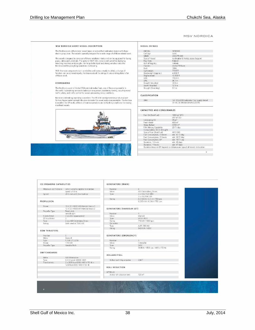
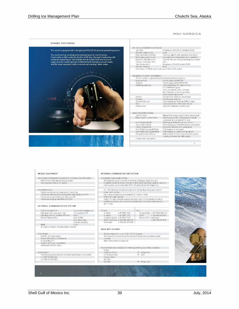
Nordica M/V Nordica – Primary IMV
OCS Outer Continental Shelf
OEMT Operations Execution Management Team
OI Old ice. Sea ice which has survived at least one summer’s melt. Topographic
features generally are smoother than FY. It may be subdivided into Second-year
(SY) ice and Multi-Year (MY) ice.
OIM Offshore Installation Manager
OSR Oil Spill Response
OSV Offshore Supply Vessel
PIC person in charge
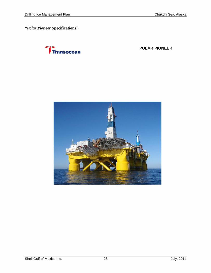
Polar Pioneer Column stabilized semi-submersible drilling unit (MODU).
psi pounds per square inch
RAR rig anchor release
RP Recommended Practice
Drilling Ice Management Plan Chukchi Sea, Alaska
Shell Gulf of Mexico Inc. 10 July, 2014
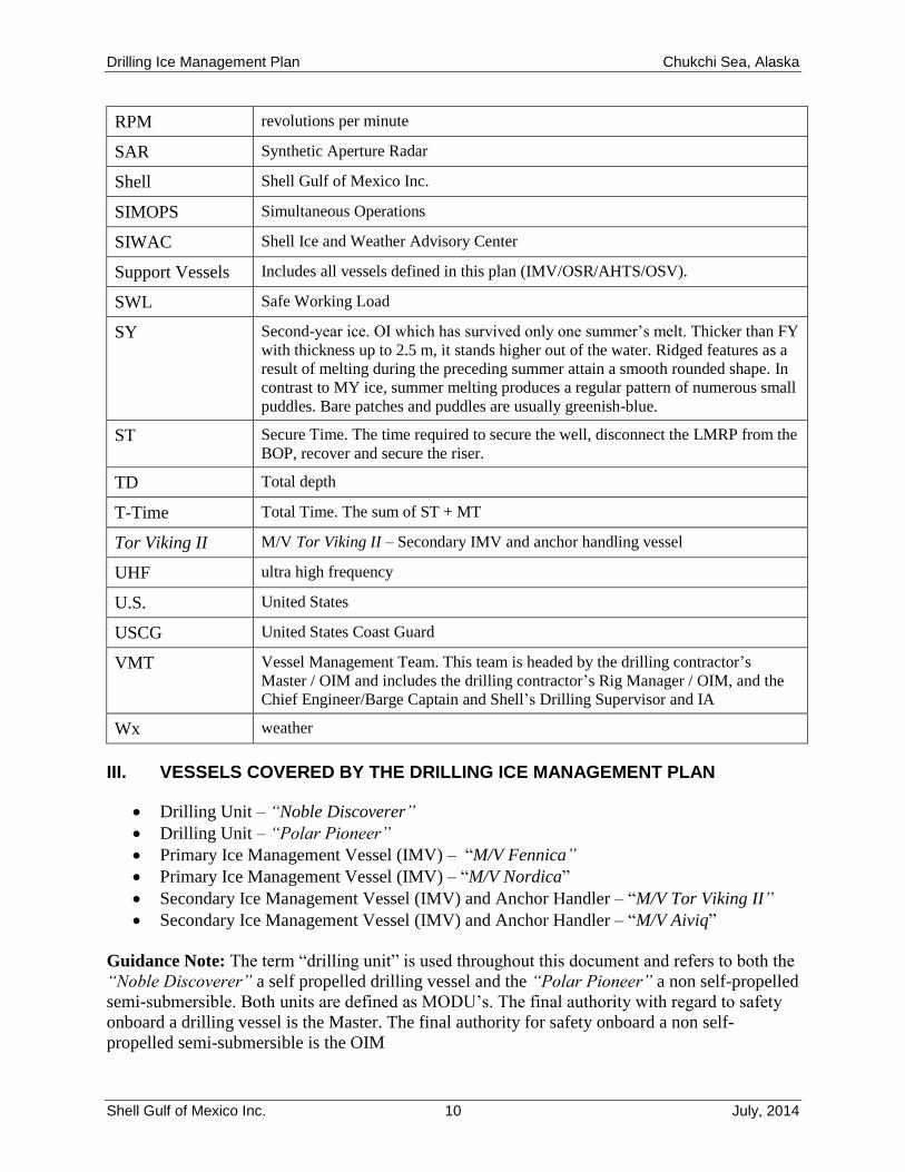
RPM revolutions per minute
SAR Synthetic Aperture Radar
Shell Shell Gulf of Mexico Inc.
SIMOPS Simultaneous Operations
SIWAC Shell Ice and Weather Advisory Center
Support Vessels Includes all vessels defined in this plan (IMV/OSR/AHTS/OSV).
SWL Safe Working Load
SY Second-year ice. OI which has survived only one summer’s melt. Thicker than FY
with thickness up to 2.5 m, it stands higher out of the water. Ridged features as a
result of melting during the preceding summer attain a smooth rounded shape. In
contrast to MY ice, summer melting produces a regular pattern of numerous small
puddles. Bare patches and puddles are usually greenish-blue.
ST Secure Time. The time required to secure the well, disconnect the LMRP from the
BOP, recover and secure the riser.
TD Total depth
T-Time Total Time. The sum of ST + MT
Tor Viking II M/V Tor Viking II – Secondary IMV and anchor handling vessel
UHF ultra high frequency
U.S. United States
USCG United States Coast Guard
VMT Vessel Management Team. This team is headed by the drilling contractor’s
Master / OIM and includes the drilling contractor’s Rig Manager / OIM, and the
Chief Engineer/Barge Captain and Shell’s Drilling Supervisor and IA
Wx weather
III. VESSELS COVERED BY THE DRILLING ICE MANAGEMENT PLAN
Drilling Unit – “Noble Discoverer”
Drilling Unit – “Polar Pioneer”
Primary Ice Management Vessel (IMV) – “M/V Fennica”
Primary Ice Management Vessel (IMV) – “M/V Nordica”
Secondary Ice Management Vessel (IMV) and Anchor Handler – “M/V Tor Viking II”
Secondary Ice Management Vessel (IMV) and Anchor Handler – “M/V Aiviq”
Guidance Note: The term “drilling unit” is used throughout this document and refers to both the
“Noble Discoverer” a self propelled drilling vessel and the “Polar Pioneer” a non self-propelled
semi-submersible. Both units are defined as MODU’s. The final authority with regard to safety
onboard a drilling vessel is the Master. The final authority for safety onboard a non self-
propelled semi-submersible is the OIM
Drilling Ice Management Plan Chukchi Sea, Alaska
Shell Gulf of Mexico Inc. 11 July, 2014
A. Drilling Units
All planned exploration drilling in the identified lease blocks will be conducted with the Noble
Discoverer and the Polar Pioneer.
The Noble Discoverer is a turret moored self-propelled drillship. Station keeping is
accomplished using a turret-moored, 8-point anchor system. The underwater fairleads prevent ice
fouling of the anchor lines. Turret mooring allows orientation of the vessel’s bow into the
prevailing metocean conditions to present minimum hull exposure to drifting ice. The vessel is
rotated around the turret by hydraulic jacks. Rotation can be augmented by the use of the fitted
bow and stern thrusters. Ice-strengthened sponsons have been retrofitted to the ship’s hull.
The Noble Discoverer is classed by Det Norske Veritas (DNV) as a Mobile Offshore Drilling
Unit (MODU) for worldwide service. It is a “1A1 Ship-Shaped Drilling Unit l” and is capable of
performing drilling operations offshore Alaska. The Noble Discoverer has been issued with a
DNV Appendix to Class stating:
“The structural strength and material quality of the ‘Ice Belt’ formed by the sponsons below the
8,950 mm A/B level, have been reviewed against the requirements for the DNV ICE-05
Additional Class Notation and found to meet those requirements (as contained in DNV Rules for
Classification of Ships, Pt 5 Ch 1, July 2006) for a design temperature of -15 degrees C.”
The Polar Pioneer is classed by Det Norske Veritas (DNV) as a Mobile Offshore Drilling Unit
(MODU) for worldwide service. It is a non-self-propelled, “SPM thruster assisted” (TA)
semisubmersible offshore drilling unit of twin-hull configuration. The rig is a “+ A1 Column
Stabilized Unit” and is capable of performing drilling operations offshore Alaska.
Positioning is accomplished with a combination of an eight-point all chain catenary mooring
system and dynamic positioning system.
Polar Pioneer was built in 1985, with unlimited operation area, in accordance with the
“Norwegian Maritime Directorate” and to “Det Norske Veritas regulations,” current at that time.
While operating in Norwegian waters, the installation, with its inventory, equipment, crew and
machinery was required to comply with current rules and regulations for operation on the
Continental Shelf of Norway.
The drilling units will undergo inspections by BSEE and Det Norske Veritas (DNV) for
certification before entering the theater. The DNV certificates will be forwarded to BOEM.
The drilling units will comply with all of the regulations of DNV, the International Maritime
Organization (IMO), and the U.S. Coast Guard (USCG). All exploration drilling operations will
be conducted under the provisions of 30 CFR Part 250 Subpart D, and other applicable
regulations and notices including those regarding the avoidance of potential drilling hazards,
safety and pollution control.
Procedures for monitoring and reacting to ice in the prospect areas are provided in the Critical
Operations and Curtailment Plan (COCP) and the Drilling Ice Management Plan (DIMP)
Drilling Ice Management Plan Chukchi Sea, Alaska
Shell Gulf of Mexico Inc. 12 July, 2014
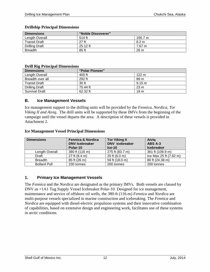
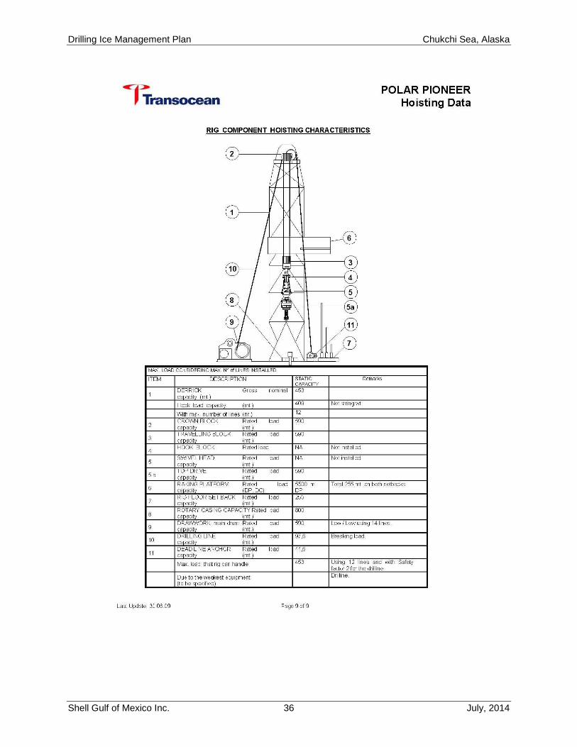
Drillship Principal Dimensions
Dimensions “Noble Discoverer”
Length Overall 514 ft 156.7 m
Transit Draft 27 ft 8.2 m
Drilling Draft 25.12 ft 7.67 m
Breadth 85 ft 26 m
Drill Rig Principal Dimensions Dimensions “Polar Pioneer”
Length Overall 400 ft 122 m
Breadth over all 292 ft 89 m
Transit Draft 30 ft 9.15 m
Drilling Draft 75.44 ft 23 m
Survival Draft 62.32 ft 19 m
B. Ice Management Vessels
Ice management support to the drilling units will be provided by the Fennica, Nordica, Tor
Viking II and Aiviq. The drill units will be supported by these IMVs from the beginning of the
campaign until the vessel departs the area. A description of these vessels is provided in
Attachment 2.
Ice Management Vessel Principal Dimensions
Dimensions Fennica & Nordica DNV Icebreaker Polar-10
Tor Viking II DNV Icebreaker Ice-10
Aiviq ABS A-3 Icebreaker
Length Overall 380 ft (116 m) 275 ft (83.7 m) 361 ft (109.9 m)
Draft 27 ft (8.4 m) 20 ft (6.0 m) Ice Max 25 ft (7.62 m)
Breadth 85 ft (26 m) 59 ft (18.0 m) 80 ft (24.38 m)
Bollard Pull 230 tonnes 200 tonnes 200 tonnes
1. Primary Ice Management Vessels
The Fennica and the Nordica are designated as the primary IMVs. Both vessels are classed by
DNV as +1A1 Tug Supply Vessel Icebreaker Polar-10. Designed for ice management,
maintenance and service of offshore oil wells, the 380-ft (116-m) Fennica and Nordica are
multi-purpose vessels specialized in marine construction and icebreaking. The Fennica and
Nordica are equipped with diesel-electric propulsion systems and their innovative combination
of capabilities, based on extensive design and engineering work, facilitates use of these systems
in arctic conditions.
Drilling Ice Management Plan Chukchi Sea, Alaska
Shell Gulf of Mexico Inc. 13 July, 2014
2. Secondary Ice Management Vessels / Anchor Handlers
The Aiviq is designated as a secondary IMV and anchor handler. The Aiviq is classed by ABS as
A1, A3 (Icebreaker). Designed for ice management, anchor handling, and maintenance and
service of offshore oil wells, the 361-ft (109.9-m) Aiviq is a multi-purpose vessel specialized in
anchor handling and icebreaking.
The Tor Viking II is designated as a secondary IMV and anchor handler. The Tor Viking II is
classed by DNV as +1A1 Supply Tug Icebreaker Ice-10. Designed for ice management, anchor
handling, and maintenance and service of offshore oil wells, the 275-ft (83.7-m) Tor Viking II is
a multipurpose vessel specialized in anchor handling and icebreaking.
Guidance Note: Ice Management Vessels supporting the drilling units may be deployed to assist
other vessels or assigned to assist other Shell drilling units as operations and ice conditions
dictate. Diverting ice management resources away from the drilling units may require a
curtailment of activities. The decision to curtail activities as a result of diverting ice management
resources away from the drilling vessel shall be made jointly by the Shell Drilling Supervisor
and the Drilling Vessel Master/OIM. The onshore Shell Wells Operations Team Leader (in
consultation with the drilling contractor’s Rig Manager) will endorse the plan or set priorities if
agreement cannot be reached at the field level.
IV. SHELL ICE AND WEATHER ADVISORY CENTER
SIWAC is an integrated forecasting service staffed 24/7 by industry-leading specialists under
Shell contract in Anchorage, Alaska. SIWAC’s primary function is to provide present and
forecast ice and weather conditions directly to field operations and planning managers during the
operational season. SIWAC provides information to decision makers and field principals to help
them minimize risks when operating in the presence of ice. To provide quality and accurate
information, SIWAC depends on skilled forecasters, subscription and public satellite imagery,
numerical models, field observations, Geographic Information System (GIS) software tools, and
a robust communication network.
Drilling Ice Management Plan Chukchi Sea, Alaska
Shell Gulf of Mexico Inc. 14 July, 2014
A. SIWAC ICE DATA INPUTS
Ice forecasts are developed and issued daily. The Lead Ice Analyst compiles available data from
subscription, specialized, and public services in ArcMAP (GIS Software) such as:
MDA RadarSat 2 imagery
MODIS satellite
Canadian Ice Services
National Ice Center
Contract weather services
Field observations
IceNav images
B. Data Transmission
Effective communication of SIWAC ice and weather guidance and reciprocal feedback and field
observations requires a robust and capable data network. The drilling units and IMVs are
equipped with high-speed data and voice satellite service that has been proven to perform well in
the U.S. Chukchi and Beaufort Seas.
Data, including satellite imagery and observations, are relayed through a file transfer protocol
(FTP) site between SIWAC and the field vessels using automated processes. This keeps both the
field and forecasters continuously refreshed with the latest information. In addition, SIWAC
maintains a secure website that allows direct, on demand access to all forecast reports and data
products. Additional information about SIWAC is provided in Appendix 3.
Drilling Ice Management Plan Chukchi Sea, Alaska
Shell Gulf of Mexico Inc. 15 July, 2014
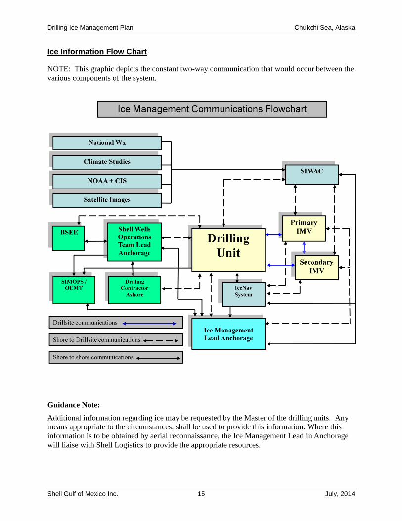
Ice Information Flow Chart
NOTE: This graphic depicts the constant two-way communication that would occur between the
various components of the system.
Guidance Note:
Additional information regarding ice may be requested by the Master of the drilling units. Any
means appropriate to the circumstances, shall be used to provide this information. Where this
information is to be obtained by aerial reconnaissance, the Ice Management Lead in Anchorage
will liaise with Shell Logistics to provide the appropriate resources.
Drilling Ice Management Plan Chukchi Sea, Alaska
Shell Gulf of Mexico Inc. 16 July, 2014
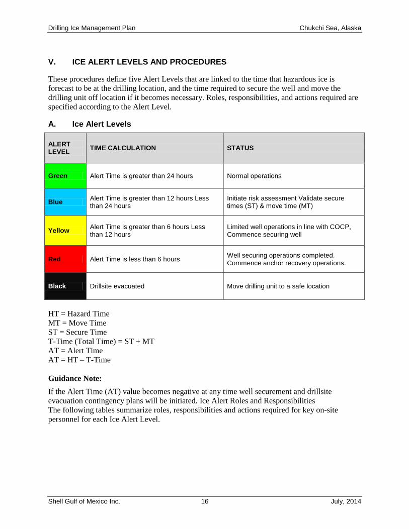
V. ICE ALERT LEVELS AND PROCEDURES
These procedures define five Alert Levels that are linked to the time that hazardous ice is
forecast to be at the drilling location, and the time required to secure the well and move the
drilling unit off location if it becomes necessary. Roles, responsibilities, and actions required are
specified according to the Alert Level.
A. Ice Alert Levels
ALERT LEVEL
TIME CALCULATION STATUS
Green Alert Time is greater than 24 hours Normal operations
Blue Alert Time is greater than 12 hours Less than 24 hours
Initiate risk assessment Validate secure times (ST) & move time (MT)
Yellow Alert Time is greater than 6 hours Less than 12 hours
Limited well operations in line with COCP, Commence securing well
Red Alert Time is less than 6 hours Well securing operations completed. Commence anchor recovery operations.
Black Drillsite evacuated Move drilling unit to a safe location
HT = Hazard Time
MT = Move Time
ST = Secure Time
T-Time (Total Time) = ST + MT
AT = Alert Time
AT = HT – T-Time
Guidance Note:
If the Alert Time (AT) value becomes negative at any time well securement and drillsite
evacuation contingency plans will be initiated. Ice Alert Roles and Responsibilities
The following tables summarize roles, responsibilities and actions required for key on-site
personnel for each Ice Alert Level.
Drilling Ice Management Plan Chukchi Sea, Alaska
Shell Gulf of Mexico Inc. 17 July, 2014
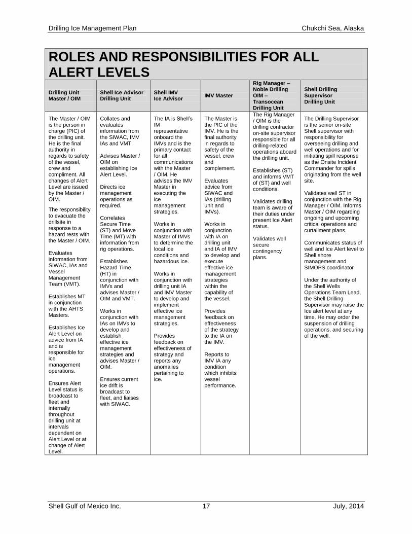
ROLES AND RESPONSIBILITIES FOR ALL ALERT LEVELS
Drilling Unit Master / OIM
Shell Ice Advisor Drilling Unit
Shell IMV Ice Advisor
IMV Master
Rig Manager – Noble Drilling OIM – Transocean Drilling Unit
Shell Drilling Supervisor Drilling Unit
The Master / OIM is the person in charge (PIC) of the drilling unit. He is the final authority in regards to safety of the vessel, crew and compliment. All changes of Alert Level are issued by the Master / OIM.
The responsibility to evacuate the drillsite in response to a hazard rests with the Master / OIM. Evaluates information from SIWAC, IAs and Vessel Management Team (VMT). Establishes MT in conjunction with the AHTS Masters. Establishes Ice Alert Level on advice from IA and is responsible for ice management operations. Ensures Alert Level status is broadcast to fleet and internally throughout drilling unit at intervals dependent on Alert Level or at change of Alert Level.
Collates and evaluates information from the SIWAC, IMV IAs and VMT. Advises Master / OIM on establishing Ice Alert Level. Directs ice management operations as required. Correlates Secure Time (ST) and Move Time (MT) with information from rig operations. Establishes Hazard Time (HT) in conjunction with IMVs and advises Master / OIM and VMT. Works in conjunction with IAs on IMVs to develop and establish effective ice management strategies and advises Master / OIM. Ensures current ice drift is broadcast to fleet, and liaises with SIWAC.
The IA is Shell’s IM representative onboard the IMVs and is the primary contact for all communications with the Master / OIM. He advises the IMV Master in executing the ice management strategies. Works in conjunction with Master of IMVs to determine the local ice conditions and hazardous ice. Works in conjunction with drilling unit IA and IMV Master to develop and implement effective ice management strategies. Provides feedback on effectiveness of strategy and reports any anomalies pertaining to ice.
The Master is the PIC of the IMV. He is the final authority in regards to safety of the vessel, crew and complement. Evaluates advice from SIWAC and IAs (drilling unit and IMVs). Works in conjunction with IA on drilling unit and IA of IMV to develop and execute effective ice management strategies within the capability of the vessel. Provides feedback on effectiveness of the strategy to the IA on the IMV. Reports to IMV IA any condition which inhibits vessel performance.
The Rig Manager / OIM is the drilling contractor on-site supervisor responsible for all drilling-related operations aboard the drilling unit. Establishes (ST) and informs VMT of (ST) and well conditions. Validates drilling team is aware of their duties under present Ice Alert status. Validates well secure contingency plans.
The Drilling Supervisor is the senior on-site Shell supervisor with responsibility for overseeing drilling and well operations and for initiating spill response as the Onsite Incident Commander for spills originating from the well site. Validates well ST in conjunction with the Rig Manager / OIM. Informs Master / OIM regarding ongoing and upcoming critical operations and curtailment plans. Communicates status of well and Ice Alert level to Shell shore management and SIMOPS coordinator Under the authority of the Shell Wells Operations Team Lead, the Shell Drilling Supervisor may raise the Ice alert level at any time. He may order the suspension of drilling operations, and securing of the well.
Drilling Ice Management Plan Chukchi Sea, Alaska
Shell Gulf of Mexico Inc. 18 July, 2014
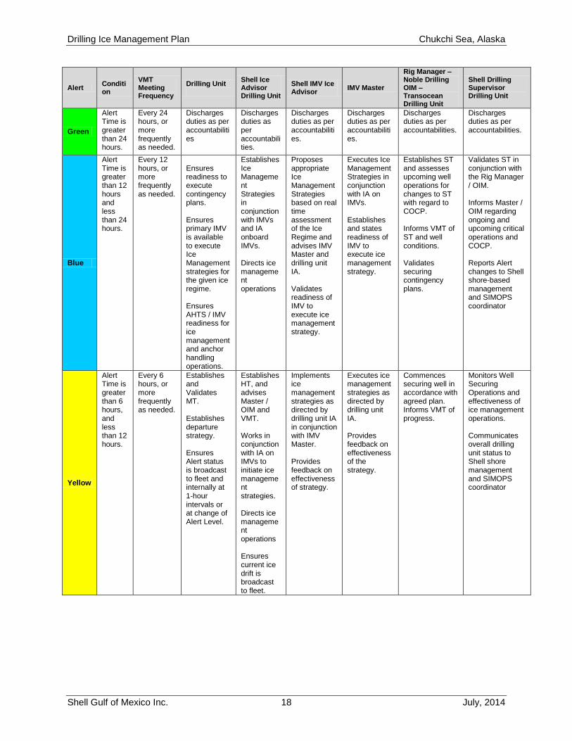
Alert Condition
VMT Meeting Frequency
Drilling Unit Master / OIM
Shell Ice Advisor Drilling Unit
Shell IMV Ice Advisor
IMV Master
Rig Manager – Noble Drilling OIM – Transocean Drilling Unit
Shell Drilling Supervisor Drilling Unit
Green
Alert Time is greater than 24 hours.
Every 24 hours, or more frequently as needed.
Discharges duties as per accountabilities
Discharges duties as per accountabilities.
Discharges duties as per accountabilities.
Discharges duties as per accountabilities.
Discharges duties as per accountabilities.
Discharges duties as per accountabilities.
Blue
Alert Time is greater than 12 hours and less than 24 hours.
Every 12 hours, or more frequently as needed.
Ensures readiness to execute contingency plans. Ensures primary IMV is available to execute Ice Management strategies for the given ice regime. Ensures AHTS / IMV readiness for ice management and anchor handling operations.
Establishes Ice Management Strategies in conjunction with IMVs and IA onboard IMVs. Directs ice management operations
Proposes appropriate Ice Management Strategies based on real time assessment of the Ice Regime and advises IMV Master and drilling unit IA. Validates readiness of IMV to execute ice management strategy.
Executes Ice Management Strategies in conjunction with IA on IMVs. Establishes and states readiness of IMV to execute ice management strategy.
Establishes ST and assesses upcoming well operations for changes to ST with regard to COCP. Informs VMT of ST and well conditions. Validates securing contingency plans.
Validates ST in conjunction with the Rig Manager / OIM. Informs Master / OIM regarding ongoing and upcoming critical operations and COCP. Reports Alert changes to Shell shore-based management and SIMOPS coordinator
Yellow
Alert Time is greater than 6 hours, and less than 12 hours.
Every 6 hours, or more frequently as needed.
Establishes and Validates MT. Establishes departure strategy. Ensures Alert status is broadcast to fleet and internally at 1-hour intervals or at change of Alert Level.
Establishes HT, and advises Master / OIM and VMT. Works in conjunction with IA on IMVs to initiate ice management strategies. Directs ice management operations Ensures current ice drift is broadcast to fleet.
Implements ice management strategies as directed by drilling unit IA in conjunction with IMV Master. Provides feedback on effectiveness of strategy.
Executes ice management strategies as directed by drilling unit IA. Provides feedback on effectiveness of the strategy.
Commences securing well in accordance with agreed plan. Informs VMT of progress.
Monitors Well Securing Operations and effectiveness of ice management operations. Communicates overall drilling unit status to Shell shore management and SIMOPS coordinator
Drilling Ice Management Plan Chukchi Sea, Alaska
Shell Gulf of Mexico Inc. 19 July, 2014
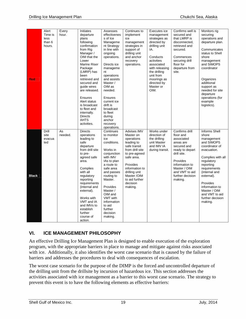
Red
Alert Time is less than 6 hours.
Every hour.
Initiates departure plans following confirmation from Rig Manager / OIM that the Lower Marine Riser Package (LMRP) has been retrieved and secured and guide wires are released. Ensures Alert status is broadcast to fleet and internally. Directs AHTS activities.
Assesses effectiveness of Ice Management Strategy in line with ongoing operations. Directs ice management operations and assists Master / OIM as needed. Ensures current ice drift is broadcast to fleet during anchor recovery operations.
Continues to implement ice management strategies in support of drilling unit and anchor recovery operations.
Executes ice management strategies as directed by drilling unit IA. Conducts activities associated with releasing the drilling unit from moorings as directed by Master or OIM.
Confirms well is secured and that LMRP is disconnected, retrieved and secured. Commences securing drill floor for departure from site.
Monitors rig securing operations and departure plan. Communicates status to Shell shore management and SIMOPS coordinator Organizes additional support as needed for site departure operations (for example logistics).
Black
Drill site evacuated
As needed.
Directs operations leading to safe departure from drill site to pre-agreed safe area. Complies with all regulatory reporting requirements (internal and external). Works with VMT and IA and IMVs to establish further course of action.
Continues to monitor ice conditions. Works in conjunction with IMV IAs to plan a route to safe area and passes routing to Master. Provides Master / OIM and VMT with information to aid further decision making.
Advises IMV Master on operations leading to safe transit from drill site to pre-agreed safe area. Provides information to drilling unit Master /OIM to aid further decision making.
Works under direction of the drilling unit Master and IMV IA during transit.
Confirms drill floor and associated areas are secured and ready to depart drill site. Provides information to Master / OIM and VMT to aid further decision making.
Informs Shell shore management and SIMOPS coordinator of evacuation. Complies with all regulatory reporting requirements (internal and external). Provides information to Master / OIM and VMT to aid further decision making.
VI. ICE MANAGEMENT PHILOSOPHY
An effective Drilling Ice Management Plan is designed to enable execution of the exploration
program, with the appropriate barriers in place to manage and mitigate against risks associated
with ice. Additionally, it also identifies the worst case scenario that is caused by the failure of
barriers and addresses the procedures to deal with consequences of escalation.
The worst case scenario for the purpose of the DIMP is the forced and uncontrolled departure of
the drilling unit from the drillsite by incursion of hazardous ice. This section addresses the
activities associated with ice management as a barrier to this worst case scenario. The strategy to
prevent this event is to have the following elements as effective barriers:
Drilling Ice Management Plan Chukchi Sea, Alaska
Shell Gulf of Mexico Inc. 20 July, 2014
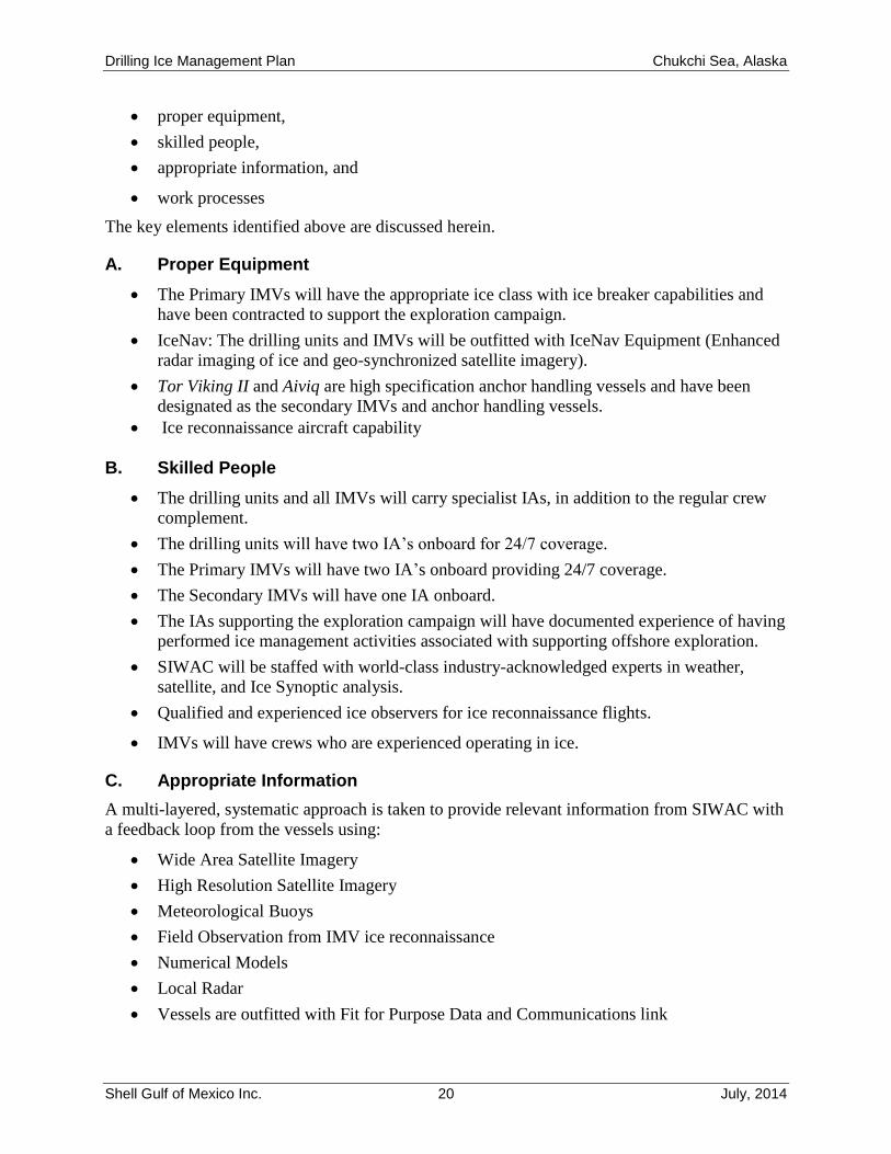
proper equipment,
skilled people,
appropriate information, and
work processes
The key elements identified above are discussed herein.
A. Proper Equipment
The Primary IMVs will have the appropriate ice class with ice breaker capabilities and
have been contracted to support the exploration campaign.
IceNav: The drilling units and IMVs will be outfitted with IceNav Equipment (Enhanced
radar imaging of ice and geo-synchronized satellite imagery).
Tor Viking II and Aiviq are high specification anchor handling vessels and have been
designated as the secondary IMVs and anchor handling vessels.
Ice reconnaissance aircraft capability
B. Skilled People
The drilling units and all IMVs will carry specialist IAs, in addition to the regular crew
complement.
The drilling units will have two IA’s onboard for 24/7 coverage.
The Primary IMVs will have two IA’s onboard providing 24/7 coverage.
The Secondary IMVs will have one IA onboard.
The IAs supporting the exploration campaign will have documented experience of having
performed ice management activities associated with supporting offshore exploration.
SIWAC will be staffed with world-class industry-acknowledged experts in weather,
satellite, and Ice Synoptic analysis.
Qualified and experienced ice observers for ice reconnaissance flights.
IMVs will have crews who are experienced operating in ice.
C. Appropriate Information
A multi-layered, systematic approach is taken to provide relevant information from SIWAC with
a feedback loop from the vessels using:
Wide Area Satellite Imagery
High Resolution Satellite Imagery
Meteorological Buoys
Field Observation from IMV ice reconnaissance
Numerical Models
Local Radar
Vessels are outfitted with Fit for Purpose Data and Communications link
Drilling Ice Management Plan Chukchi Sea, Alaska
Shell Gulf of Mexico Inc. 21 July, 2014
D. Work Process
A systematic approach for risk mitigation is adopted by developing effective work processes.
Development of effective ice management strategies based on available information
(Global and Local)
Deployment of assets to deliver strategy:
Threat Sectors identified
Assess manageability of ice feature (preferably by trial breaking as this is the only way to
determine manageability)
Appropriate management of ice feature (breaking/deflecting)
Primary Icebreaker deployed at an effective perimeter to reduce floes to manageable size
in advance of Hazardous Ice triggering an increase in Alert Level
Scheduled VMT meetings (Frequency Dictated by Alert levels)
Planning/Coordination meetings with specific focus on Ice Alert Levels
VII. WELL SUSPENSION PROCEDURES
Effectiveness of the DIMP is dependent upon being able to accurately establish HT, ST and MT.
ST is time taken to secure the well, disconnect and retrieve the LMRP.
As part of securing the well, well suspension procedures have been established. These
procedures will be contained within the drilling unit operating procedures. Return to the drill site
following exit due to the threat of Hazardous Ice is covered in Section IX.
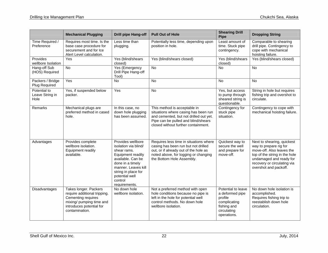
A. Well Suspension Options
Securing and suspending the well can be accomplished by several means. The base case is to
suspend the well with mechanical and/or cement plugs. This method is to be used for Ice Alert
Level calculations. Should ice or well conditions develop where ST must be reduced, the
following contingencies and options or combination thereof can be chosen. The option or
contingency will be dependent upon well conditions, environmental conditions and (or)
equipment limitations. Shell will employ the most effective suspension procedure under the
specific circumstances at the time.
Relevant information associated with well suspension will be documented in the daily drilling
reports. The BSEE field representative will be apprised, and relevant records will be submitted
to BSEE. Potential well suspension options are listed in the following table.
Drilling Ice Management Plan Chukchi Sea, Alaska
Shell Gulf of Mexico Inc. 22 July, 2014
Mechanical Plugging Drill pipe Hang-off Pull Out of Hole
Shearing Drill Pipe
Dropping String
Time Required / Preference
Requires most time. Is the base case procedure for securement and for Ice Alert Level calculation.
Less time than plugging.
Potentially less time, depending upon position in hole.
Least amount of time. Stuck pipe contingency.
Comparable to shearing drill pipe. Contingency to cope with mechanical hoisting failure.
Provides wellbore Isolation
Yes Yes (blind/shears closed)
Yes (blind/shears closed) Yes (blind/shears closed)
Yes (blind/shears closed)
Hang-off Sub (HOS) Required
No Yes (Emergency Drill Pipe Hang-off Tool)
No No No
Packers / Bridge Plug Required
Yes No No No No
Potential to Leave String in Hole
Yes, if suspended below packer.
Yes No Yes, but access to pump through sheared string is questionable.
String in hole but requires fishing trip and overshot to circulate.
Remarks Mechanical plugs are preferred method in cased hole.
In this case, no down hole plugging has been assumed.
This method is acceptable in situations where casing has been run and cemented, but not drilled out yet. Pipe can be pulled and blind/shears closed without further containment.
Contingency for stuck pipe situation.
Contingency to cope with mechanical hoisting failure.
Advantages Provides complete wellbore isolation. Equipment readily available.
Provides wellbore isolation via blind/ shear rams. Equipment readily available. Can be done in a timely manner. Leaves kill string in place for potential well control requirements.
Requires less time in situations where casing has been run but not drilled out, or if already out of the hole as noted above, for logging or changing the Bottom Hole Assembly.
Quickest way to secure the well and prepare for move-off.
Next to shearing, quickest way to prepare rig for move-off. Also leaves the top of the string in the hole undamaged and ready for recovery or circulating via overshot and packoff.
Disadvantages Takes longer. Packers require additional tripping. Cementing requires mixing/ pumping time and introduces potential for contamination.
No down hole wellbore isolation.
Not a preferred method with open hole conditions because no pipe is left in the hole for potential well control methods. No down hole wellbore isolation.
Potential to leave a deformed pipe profile complicating fishing and circulating operations.
No down hole isolation is accomplished. Requires fishing trip to reestablish down hole circulation.
Drilling Ice Management Plan Chukchi Sea, Alaska
Shell Gulf of Mexico Inc. 23 July, 2014
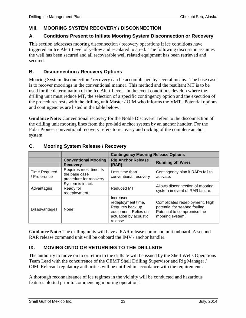
VIII. MOORING SYSTEM RECOVERY / DISCONNECTION
A. Conditions Present to Initiate Mooring System Disconnection or Recovery
This section addresses mooring disconnection / recovery operations if ice conditions have
triggered an Ice Alert Level of yellow and escalated to a red. The following discussion assumes
the well has been secured and all recoverable well related equipment has been retrieved and
secured.
B. Disconnection / Recovery Options
Mooring System disconnection / recovery can be accomplished by several means. The base case
is to recover moorings in the conventional manner. This method and the resultant MT is to be
used for the determination of the Ice Alert Level. In the event conditions develop where the
drilling unit must reduce MT, the selection of a specific contingency option and the execution of
the procedures rests with the drilling unit Master / OIM who informs the VMT. Potential options
and contingencies are listed in the table below.
Guidance Note: Conventional recovery for the Noble Discoverer refers to the disconnection of
the drilling unit mooring lines from the pre-laid anchor system by an anchor handler. For the
Polar Pioneer conventional recovery refers to recovery and racking of the complete anchor
system
C. Mooring System Release / Recovery
Contingency Mooring Release Options
Conventional Mooring Recovery
Rig Anchor Release (RAR)
Running off Wires
Time Required / Preference
Requires most time. Is the base case procedure for recovery
Less time than conventional recovery
Contingency plan if RARs fail to activate.
Advantages System is intact. Ready for redeployment.
Reduced MT Allows disconnection of mooring system in event of RAR failure.
Disadvantages None
Increased redeployment time. Requires back up equipment. Relies on actuation by acoustic release.
Complicates redeployment. High potential for seabed fouling. Potential to compromise the mooring system.
Guidance Note: The drilling units will have a RAR release command unit onboard. A second
RAR release command unit will be onboard the IMV / anchor handler.
IX. MOVING ONTO OR RETURNING TO THE DRILLSITE
The authority to move on to or return to the drillsite will be issued by the Shell Wells Operations
Team Lead with the concurrence of the OEMT Shell Drilling Supervisor and Rig Manager /
OIM. Relevant regulatory authorities will be notified in accordance with the requirements.
A thorough reconnaissance of ice regimes in the vicinity will be conducted and hazardous
features plotted prior to commencing mooring operations.
Drilling Ice Management Plan Chukchi Sea, Alaska
Shell Gulf of Mexico Inc. 24 July, 2014
An Ice Alert Level of green, together with a favorable ice condition forecast is required before
mooring commences.
Recognizing HT will be the only argument available for the Alert Level calculation before
mooring, a minimum HT of 60 hours and a minimum distance of 30 miles to Hazardous Ice is
required to give a reasonable period of time to set moorings and stay within Green Alert at
completion of mooring.
Upon authorization by the Shell Wells Operations Team Lead, the final decision to move on to
or return to the drillsite is dependent upon the drilling unit Master or OIM who is advised by the
VMT. The Master / OIM and VMT will assess the various operational, weather and ice
parameters with input from the drilling unit IA supported by the IMV Masters and the IAs to
determine the practicality of the decision. A decision to commence mooring operations assumes
a realistic expectation that the drilling unit will be able to stay on location and commence drilling
operations for a productive length of time. The OEMT will be informed of all decisions as they
are made.
X. TRAINING
All personnel will be made aware of their roles and responsibilities within this DIMP through a
training session on each vessel. This training will also include a Table Top Exercise, which will
be executed prior to beginning operations, providing exposure to and test communications and
procedures of the COCP, and the DIMP. Participants at the table top exercise will include:
Shell and Wells leadership
Rig Crews (both Drilling and Marine Contractor staff)
Oil Spill Response (OSR) representative
SIWAC representatives
BSEE Operations representatives
IMV Masters or Senior officers
IAs
Alaska Logistics ( Marine and Aviation ) Representatives
SIMOPS Coordinators
Observations from the Table Top Exercise will be documented.
Drilling Ice Management Plan Chukchi Sea, Alaska
Shell Gulf of Mexico Inc. 25 July, 2014
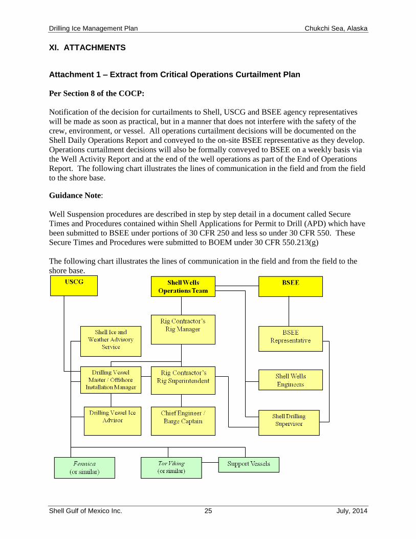
XI. ATTACHMENTS
Attachment 1 – Extract from Critical Operations Curtailment Plan
Per Section 8 of the COCP:
Notification of the decision for curtailments to Shell, USCG and BSEE agency representatives
will be made as soon as practical, but in a manner that does not interfere with the safety of the
crew, environment, or vessel. All operations curtailment decisions will be documented on the
Shell Daily Operations Report and conveyed to the on-site BSEE representative as they develop.
Operations curtailment decisions will also be formally conveyed to BSEE on a weekly basis via
the Well Activity Report and at the end of the well operations as part of the End of Operations
Report. The following chart illustrates the lines of communication in the field and from the field
to the shore base.
Guidance Note:
Well Suspension procedures are described in step by step detail in a document called Secure
Times and Procedures contained within Shell Applications for Permit to Drill (APD) which have
been submitted to BSEE under portions of 30 CFR 250 and less so under 30 CFR 550. These
Secure Times and Procedures were submitted to BOEM under 30 CFR 550.213(g)
The following chart illustrates the lines of communication in the field and from the field to the
shore base.
Drilling Ice Management Plan Chukchi Sea, Alaska
Shell Gulf of Mexico Inc. 26 July, 2014
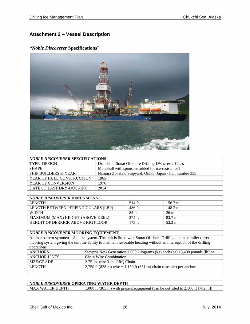
Attachment 2 – Vessel Description
“Noble Discoverer Specifications”
NOBLE DISCOVERER SPECIFICATIONS
TYPE- DESIGN Drillship - Sonat Offshore Drilling Discoverer Class
SHAPE Monohull with sponsons added for ice-resistance1
SHIP BUILDERS & YEAR Namura Zonshno Shipyard, Osaka, Japan - hull number 355
YEAR OF HULL CONSTRUCTION 1965
YEAR OF CONVERSION 1976
DATE OF LAST DRY-DOCKING 2014
NOBLE DISCOVERER DIMENSIONS
LENGTH 514 ft 156.7 m
LENGTH BETWEEN PERPINDICULARS (LBP) 486 ft 148.2 m
WIDTH 85 ft 26 m
MAXIMUM (MAX) HEIGHT (ABOVE KEEL) 274 ft 83.7 m
HEIGHT OF DERRICK ABOVE RIG FLOOR 175 ft 53.3 m
NOBLE DISCOVERER MOORING EQUIPMENT
Anchor pattern symmetric 8 point system. The unit is fitted with Sonat Offshore Drilling patented roller turret
mooring system giving the unit the ability to maintain favorable heading without an interruption of the drilling
operations.
ANCHORS Stevpris New Generation 7,000 kilograms (kg) each (ea) 15,400 pounds (lb) ea.
ANCHOR LINES Chain Wire Combination
SIZE/GRADE 2.75-in. wire 3-in. ORQ Chain
LENGTH 2,750 ft (838 m) wire + 1,150 ft (351 m) chain (useable) per anchor
NOBLE DISCOVERER OPERATING WATER DEPTH
MAX WATER DEPTH 1,000 ft (305 m) with present equipment (can be outfitted to 2,500 ft [762 m])
Drilling Ice Management Plan Chukchi Sea, Alaska
Shell Gulf of Mexico Inc. 27 July, 2014
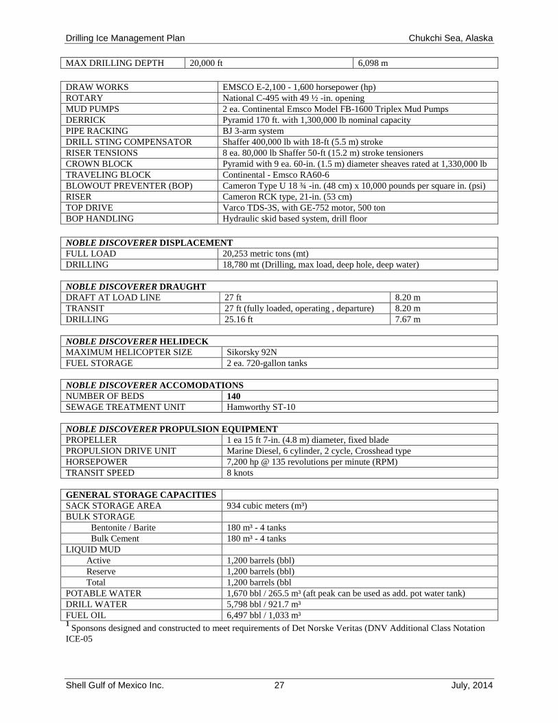
MAX DRILLING DEPTH 20,000 ft 6,098 m
DRAW WORKS EMSCO E-2,100 - 1,600 horsepower (hp)
ROTARY National C-495 with 49 ½ -in. opening
MUD PUMPS 2 ea. Continental Emsco Model FB-1600 Triplex Mud Pumps
DERRICK Pyramid 170 ft. with 1,300,000 lb nominal capacity
PIPE RACKING BJ 3-arm system
DRILL STING COMPENSATOR Shaffer 400,000 lb with 18-ft (5.5 m) stroke
RISER TENSIONS 8 ea. 80,000 lb Shaffer 50-ft (15.2 m) stroke tensioners
CROWN BLOCK Pyramid with 9 ea. 60-in. (1.5 m) diameter sheaves rated at 1,330,000 lb
TRAVELING BLOCK Continental - Emsco RA60-6
BLOWOUT PREVENTER (BOP) Cameron Type U 18 ¾ -in. (48 cm) x 10,000 pounds per square in. (psi)
RISER Cameron RCK type, 21-in. (53 cm)
TOP DRIVE Varco TDS-3S, with GE-752 motor, 500 ton
BOP HANDLING Hydraulic skid based system, drill floor
NOBLE DISCOVERER DISPLACEMENT
FULL LOAD 20,253 metric tons (mt)
DRILLING 18,780 mt (Drilling, max load, deep hole, deep water)
NOBLE DISCOVERER DRAUGHT
DRAFT AT LOAD LINE 27 ft 8.20 m
TRANSIT 27 ft (fully loaded, operating , departure) 8.20 m
DRILLING 25.16 ft 7.67 m
NOBLE DISCOVERER HELIDECK
MAXIMUM HELICOPTER SIZE Sikorsky 92N
FUEL STORAGE 2 ea. 720-gallon tanks
NOBLE DISCOVERER ACCOMODATIONS
NUMBER OF BEDS 140
SEWAGE TREATMENT UNIT Hamworthy ST-10
NOBLE DISCOVERER PROPULSION EQUIPMENT
PROPELLER 1 ea 15 ft 7-in. (4.8 m) diameter, fixed blade
PROPULSION DRIVE UNIT Marine Diesel, 6 cylinder, 2 cycle, Crosshead type
HORSEPOWER 7,200 hp @ 135 revolutions per minute (RPM)
TRANSIT SPEED 8 knots
GENERAL STORAGE CAPACITIES
SACK STORAGE AREA 934 cubic meters (m³)
BULK STORAGE
Bentonite / Barite 180 m³ - 4 tanks
Bulk Cement 180 m³ - 4 tanks
LIQUID MUD
Active 1,200 barrels (bbl)
Reserve 1,200 barrels (bbl)
Total 1,200 barrels (bbl
POTABLE WATER 1,670 bbl / 265.5 m³ (aft peak can be used as add. pot water tank)
DRILL WATER 5,798 bbl / 921.7 m³
FUEL OIL 6,497 bbl / 1,033 m³ 1
Sponsons designed and constructed to meet requirements of Det Norske Veritas (DNV Additional Class Notation
ICE-05
Drilling Ice Management Plan Chukchi Sea, Alaska
Shell Gulf of Mexico Inc. 28 July, 2014
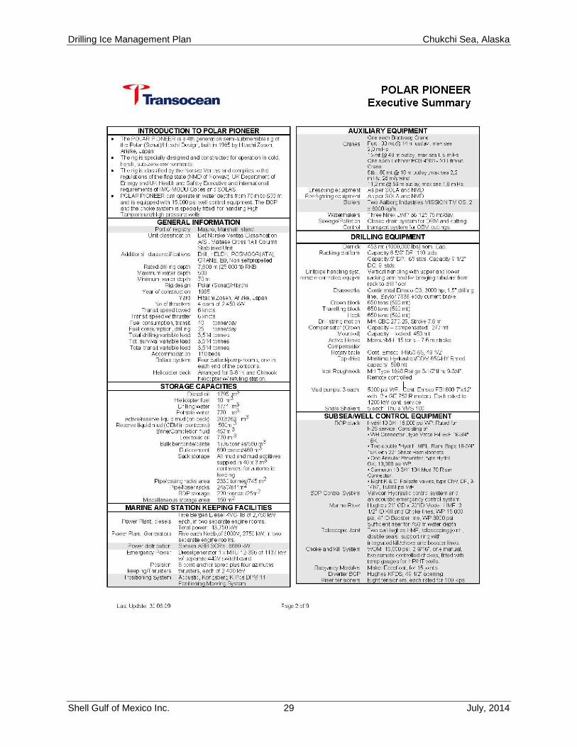
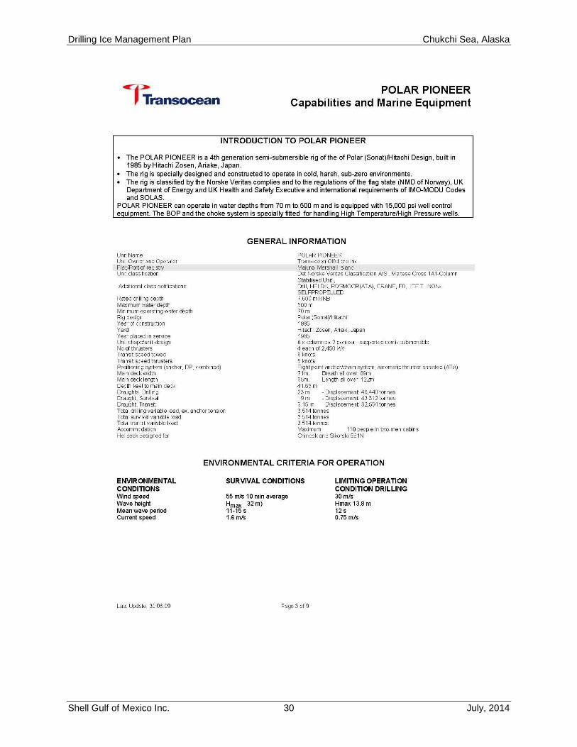
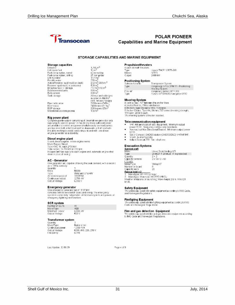
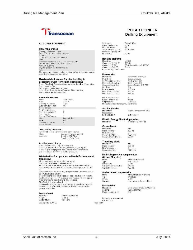
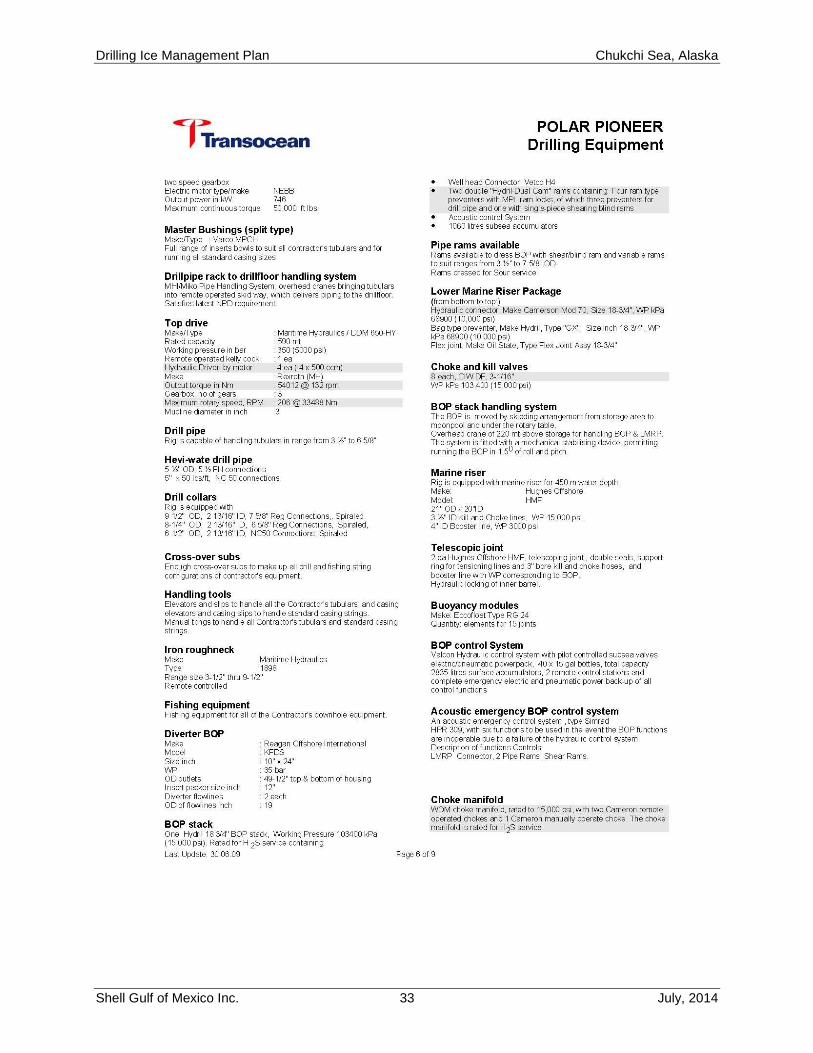
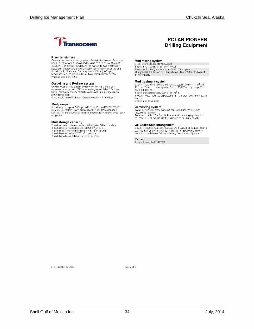
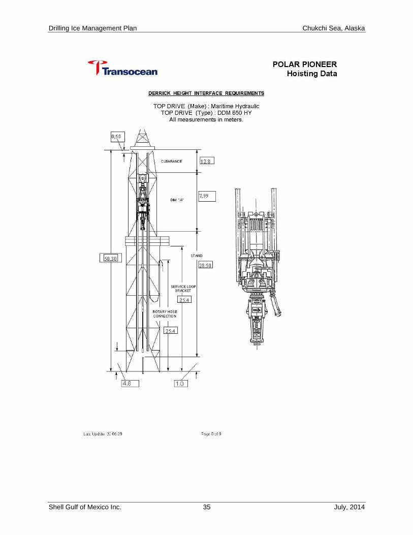
“Polar Pioneer Specifications”
Drilling Ice Management Plan Chukchi Sea, Alaska
Shell Gulf of Mexico Inc. 29 July, 2014
Drilling Ice Management Plan Chukchi Sea, Alaska
Shell Gulf of Mexico Inc. 30 July, 2014
Drilling Ice Management Plan Chukchi Sea, Alaska
Shell Gulf of Mexico Inc. 31 July, 2014
Drilling Ice Management Plan Chukchi Sea, Alaska
Shell Gulf of Mexico Inc. 32 July, 2014
Drilling Ice Management Plan Chukchi Sea, Alaska
Shell Gulf of Mexico Inc. 33 July, 2014
Drilling Ice Management Plan Chukchi Sea, Alaska
Shell Gulf of Mexico Inc. 34 July, 2014
Drilling Ice Management Plan Chukchi Sea, Alaska
Shell Gulf of Mexico Inc. 35 July, 2014
Drilling Ice Management Plan Chukchi Sea, Alaska
Shell Gulf of Mexico Inc. 36 July, 2014
Drilling Ice Management Plan Chukchi Sea, Alaska
Shell Gulf of Mexico Inc. 37 July, 2014
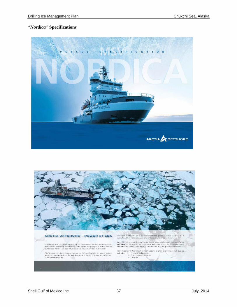
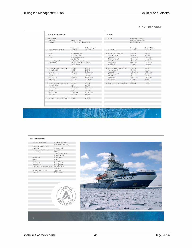
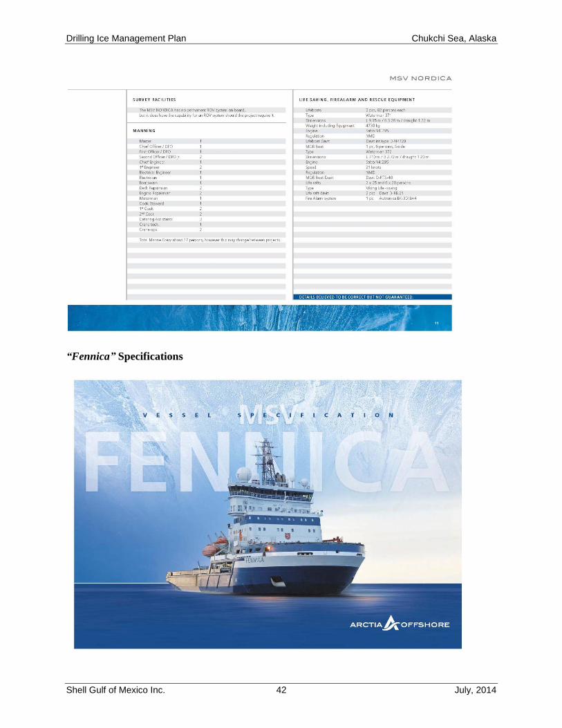
“Nordica” Specifications
Drilling Ice Management Plan Chukchi Sea, Alaska
Shell Gulf of Mexico Inc. 38 July, 2014
Drilling Ice Management Plan Chukchi Sea, Alaska
Shell Gulf of Mexico Inc. 39 July, 2014
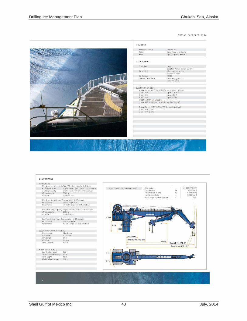
Drilling Ice Management Plan Chukchi Sea, Alaska
Shell Gulf of Mexico Inc. 40 July, 2014
Drilling Ice Management Plan Chukchi Sea, Alaska
Shell Gulf of Mexico Inc. 41 July, 2014
Drilling Ice Management Plan Chukchi Sea, Alaska
Shell Gulf of Mexico Inc. 42 July, 2014
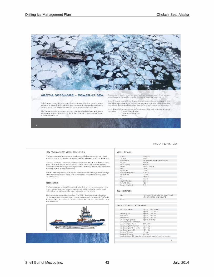
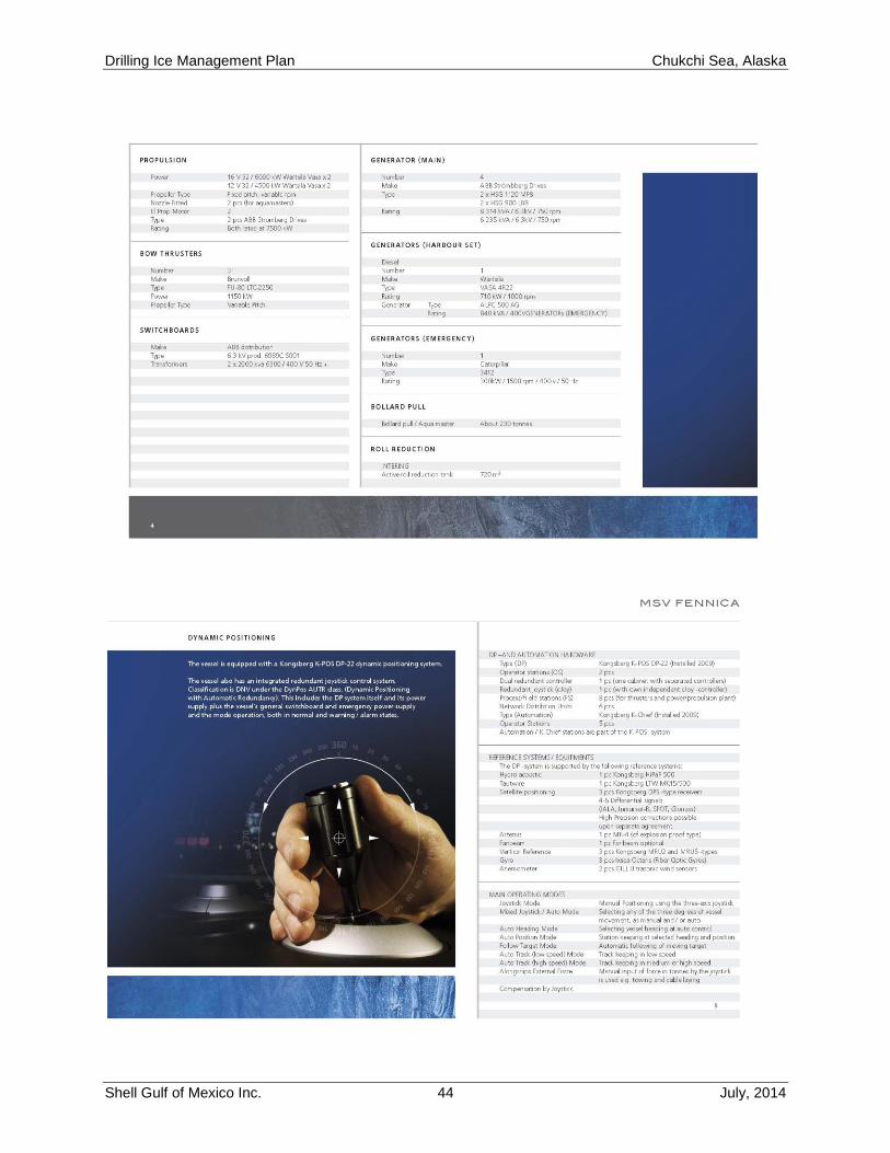
“Fennica” Specifications
Drilling Ice Management Plan Chukchi Sea, Alaska
Shell Gulf of Mexico Inc. 43 July, 2014
Drilling Ice Management Plan Chukchi Sea, Alaska
Shell Gulf of Mexico Inc. 44 July, 2014
Drilling Ice Management Plan Chukchi Sea, Alaska
Shell Gulf of Mexico Inc. 45 July, 2014
Drilling Ice Management Plan Chukchi Sea, Alaska
Shell Gulf of Mexico Inc. 46 July, 2014
Drilling Ice Management Plan Chukchi Sea, Alaska
Shell Gulf of Mexico Inc. 47 July, 2014
Drilling Ice Management Plan Chukchi Sea, Alaska
Shell Gulf of Mexico Inc. 48 July, 2014
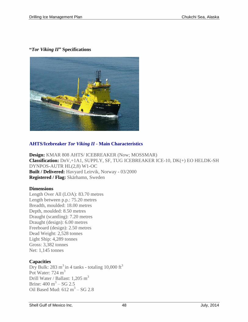
“Tor Viking II” Specifications
AHTS/Icebreaker Tor Viking II - Main Characteristics
Design: KMAR 808 AHTS/ ICEBREAKER (Now; MOSSMAR)
Classification: DnV,+1A1, SUPPLY, SF, TUG ICEBREAKER ICE-10, DK(+) EO HELDK-SH
DYNPOS-AUTR HL(2,8) W1-OC
Built / Delivered: Havyard Leirvik, Norway - 03/2000
Registered / Flag: Skärhamn, Sweden
Dimensions
Length Over All (LOA): 83.70 metres
Length between p.p.: 75.20 metres
Breadth, moulded: 18.00 metres
Depth, moulded: 8.50 metres
Draught (scantling): 7.20 metres
Draught (design): 6.00 metres
Freeboard (design): 2.50 metres
Dead Weight: 2,528 tonnes
Light Ship: 4,289 tonnes
Gross: 3,382 tonnes
Net: 1,145 tonnes
Capacities
Dry Bulk: 283 m3
in 4 tanks - totaling 10,000 ft3
Pot Water: 724 m3
Drill Water / Ballast: 1,205 m3
Brine: 400 m3 – SG 2.5
Oil Based Mud: 612 m3 – SG 2.8
Drilling Ice Management Plan Chukchi Sea, Alaska
Shell Gulf of Mexico Inc. 49 July, 2014
Base Oil: 242 m3
Fuel Oil: 1,190 m3 Marine Gas Oil (Diesel)
Urea: 94 m3
Diesel Overflow: 21 m3 with alarm
Diesel Service / Settling: 2 x 20 m3
Deck Load: Abt 1,350 ts
Deck Area: 603 m2 / 40.20 m x 15.0 m
All products in dedicated tanks – no dual purpose tanks
Propulsion
Main Engine: MAK 18,300 BHP - 4 eng (father/son) 2 x 3,840 kW + 2 x 2,880 kW = 13,440 kW
Thrusters: Bow 1,200 BHP in tunnel (Electr) + 1,200 BHP 360 deg retractable = 2,400 BHP:
Stern 1,200 BHP in tunnel
Bollard Pull: Bollard Pull: 202 continuous (DnV certified) / Abt. 210 max pull
Speed/Consumption: 16 knots – Abt. 42.7 MT / 24 hrs at 6.0 metres draught , 12 knots – Abt.
25.0 MT
Towing & Anchor Handling Equipment
AHT Winch: Brattvaag towing/anchor handling winch 400 ts pull / 550 ts brake holding caps
AHT Drum: One of 1,400 mm dia. x 3,750 dia. x (1,250 mm + 1,250 mm) length
Wire Capacity: 2 x 1,900 metres of 77 mm wire or 2 x 1,650 metres of 83 mm wire
AH Drum: One of 1,400 mm dia. x 3,750 mm dia. x 3,000 mm length
Wire Capacity: 4,100 metres of 83 mm wire
Winch Control: TOWCON 2000 Automatic Control with printer
Pennant Reels: One off 2 x 1,500 m of 77 mm wire or 2 x 1,300 m of 83 mm wire capacity: One
off 3,400 m of 77 mm wire or 1 x 3,100 m of 83 mm wire capacity
Large Reel Inner Core: 1,500 mm dia.
Cable Lifters: 2 x 76 mm and 2 x 84 mm onboard
Chain Lockers: 2 x 129 m 3 / giving abt 2 x 6,000 ft of 3 inch chain
Shark Jaws: 2 pairs of Karm Forks arranged for chain up to 165 mm dia. / 750 ts SWL
Inserts for handling of 65, 75, 85, 100, and 120 mm dia. wire/chain
Stern Roller: One of 3,5 metres dia. x 6.0 metres length – SWL 500 ts
Guide Pins: 2 pairs Karm Fork Hydraulic pins – SWL 170 ts
Deck Equipment
Capstans: 2 x 15 ts pull
Tugger Winches: 2 x 15 ts pull
Smit Brackets: One bracket on B Deck Forward – SWL 250 ts
Cranes: 1 hydraulic crane on fore cargo deck giving 6 / 12 ts at 20/10 m arm (360 deg)
: 1 telescopic crane on aft cargo deck giving 1.5 / 3 ts at 15/10 m arm (360 degr)
: 1 hydraulic crane on for-castle deck for stores etc.
Windlass: 1 hydraulic windlass / mooring winch. 2 declutch-able drums 46 mm K3 chain
Accommodation: Accommodation of a total of 23 persons, including crew.
All accommodation equipped with air-condition and humidification facilities.
Dynamic Positioning
The vessel is equipped with Kongsberg Simrad SDP 21 Redundant DP System – Green DP.
Drilling Ice Management Plan Chukchi Sea, Alaska
Shell Gulf of Mexico Inc. 50 July, 2014
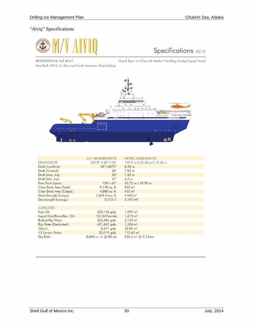
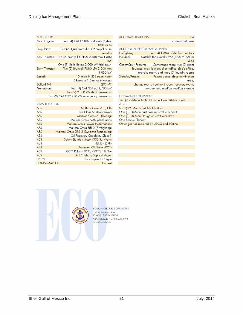
“Aiviq” Specifications
Drilling Ice Management Plan Chukchi Sea, Alaska
Shell Gulf of Mexico Inc. 51 July, 2014
Drilling Ice Management Plan Chukchi Sea, Alaska
Shell Gulf of Mexico Inc. 52 July, 2014
Attachment 3 – Shell Ice and Weather Advisory Center
Operational Support Overview
Safe and efficient offshore operations in the Arctic are contingent upon quality and timely ice
and weather forecasts. Using state of the art satellite technology, large areas of the Beaufort and
Chukchi Seas are monitored remotely by the SIWAC to track movement of ice and make
estimates of its type and concentration.
Synthetic Aperture Radar (SAR) instruments on board the RADARSAT 2 satellite are contracted
to acquire necessary images of sea ice over areas of interest several times per week. These
images are transmitted to ground stations, processed, and made available for analysis within
hours of acquisition. Interpretation of the ice edge and features are performed by experienced
specialists using powerful mapping software to produce ice charts that are considerably more
detailed than those available from national ice centers. These charts are then distributed to
operational personnel and planning managers and can be validated or ground-truthed using actual
ice regime assessments from the IMV fleet.
Knowing the location and composition of the ice at any given moment is a valuable tool;
however, it is not enough. It is important to forecast how the ice may change over time. A
complementary component of ice forecasting is quality weather information. Weather conditions
in the Arctic are among the most severe on the planet and change dramatically in a short time.
National weather services do not provide measurements and forecasts that sufficiently resolve
the conditions over small areas or short time spans in the Arctic offshore. Therefore, dedicated
meteorologists with Arctic forecasting experience are employed full time to produce accurate
snapshots of the current conditions and reliable forecasts of weather conditions into the future.
Using global weather models, such as ECMWF and GFS numerical weather model as a starting
point, the meteorologists produce a high resolution grid in proprietary modeling software of
weather parameters, such as atmospheric pressure, wind speed, and wave height, that have been
corrected based on local observations from Shell’s vessels at sea, meteorological buoys, and
coastal weather stations. The result is a model that accurately reflects current and forecast
weather conditions over short distances in the Beaufort and Chukchi Seas, making marine
operations and vessel transits safer and more responsible. Without this innovative forecast effort,
weather products from other sources tend to describe the average or general conditions that one
could expect over large areas, such as the entire U.S. Beaufort Sea, which results in local
conditions rarely matching what is forecast.
The wind vectors, which are a set of points indicating the speed and direction of the wind
distributed over the Beaufort and Chukchi Seas, and other output from the weather model are
applied to the ice charts in the mapping software. This allows the ice analyst to assess the effect
of wind and weather systems on the future movement and development of the ice.
Drilling Ice Management Plan Chukchi Sea, Alaska
Shell Gulf of Mexico Inc. 53 July, 2014
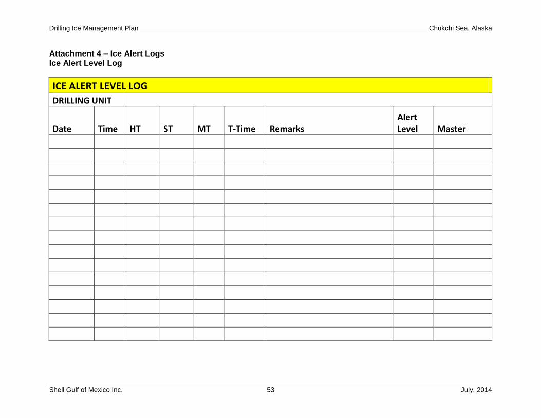
Attachment 4 – Ice Alert Logs Ice Alert Level Log
ICE ALERT LEVEL LOG
DRILLING UNIT
Date Time HT ST MT T-Time Remarks Alert Level Master
Drilling Ice Management Plan Chukchi Sea, Alaska
Shell Gulf of Mexico Inc. 54 July, 2014
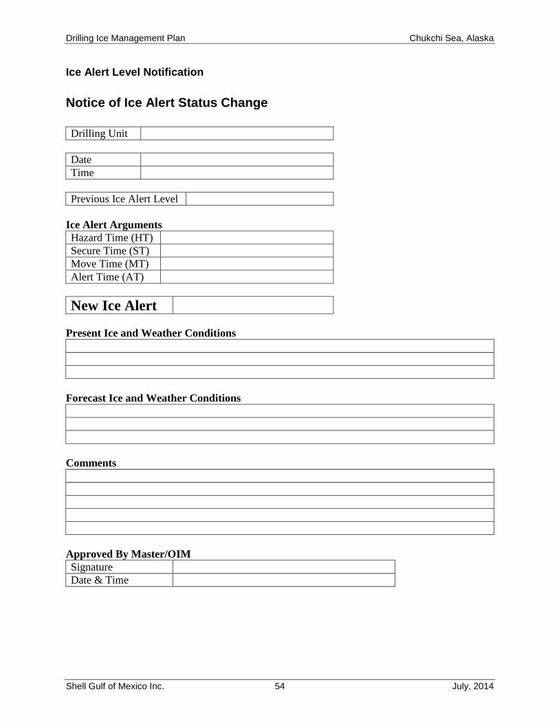
Ice Alert Level Notification
Notice of Ice Alert Status Change
Drilling Unit
Date
Time
Previous Ice Alert Level
Ice Alert Arguments
Hazard Time (HT)
Secure Time (ST)
Move Time (MT)
Alert Time (AT)
New Ice Alert
Present Ice and Weather Conditions
Forecast Ice and Weather Conditions
Comments
Approved By Master/OIM
Signature Date & Time
Drilling Ice Management Plan Chukchi Sea, Alaska
Shell Gulf of Mexico Inc. 55 July, 2014
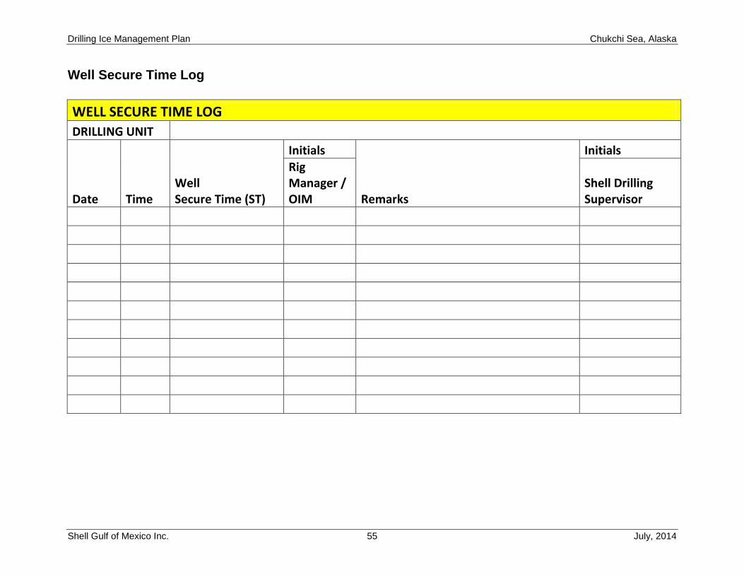
Well Secure Time Log
WELL SECURE TIME LOG
DRILLING UNIT
Date Time Well Secure Time (ST)
Initials
Remarks
Initials
Rig Manager / OIM
Shell Drilling Supervisor
Recommended