Engineering Department
DRAWING STANDARD SPECIFICATIONS
June 2017
City of Surrey TABLE of CONTENTS Page i Engineering Department Drawing Standard Specifications June 2017
Page
1 INTRODUCTION ............................................................................................................. 1
1.1 Overview .......................................................................................................................................... 1
1.2 Measurements / Units ....................................................................................................................... 1
1.3 Hardcopy and Digital Template ....................................................................................................... 1
2 DRAWING STANDARDS ............................................................................................... 2
2.1 General Hard Copy Drawing Standards ........................................................................................... 2
2.2 Survey and Drawing Reference (Horizontal and Vertical Datums) ................................................. 4
2.3 Chainage and Baselines.................................................................................................................... 5
2.3.1 Chainage .............................................................................................................................. 5 2.3.2 Baselines ............................................................................................................................. 5
2.4 Plan and Profile Drawings ............................................................................................................... 6
2.4.1 Plan View ............................................................................................................................ 6 2.4.2 Profile View ........................................................................................................................ 8
2.5 Additional Standards for Specific Service Drawings ....................................................................... 9
2.5.1 Storm and Sanitary Sewers ................................................................................................. 9 2.5.2 Roads ................................................................................................................................. 10 2.5.3 Water ................................................................................................................................. 10 2.5.4 Street Light Works ............................................................................................................ 11 2.5.5 Sidewalks .......................................................................................................................... 11 2.5.6 Cross-Sections ................................................................................................................... 11 2.5.7 Intersections ...................................................................................................................... 12
3 DRAWING SUBMISSION PROCESS ......................................................................... 13
3.1 Submission Process ........................................................................................................................ 13
3.2 Sign and Seal .................................................................................................................................. 14
4 DIGITAL FILE SUBMISSION ..................................................................................... 16
4.1 Spatial Coordinate System ............................................................................................................. 16
4.2 Naming Convention for Digital File .............................................................................................. 16
4.3 Submission of Digital File ............................................................................................................. 17
City of Surrey TABLE of CONTENTS Page ii Engineering Department Drawing Standard Specifications June 2017
List of Tables
Table 2.1.1: Asset / Service Feature Types Table 2.2.1: Survey Control Monument Reference Data Table 2.5.1: Geometric Curve and Curb Return Data Table 4.2.1: File Name Abbreviation per Drawing Phase List of Appendices Appendix I: Road Templates
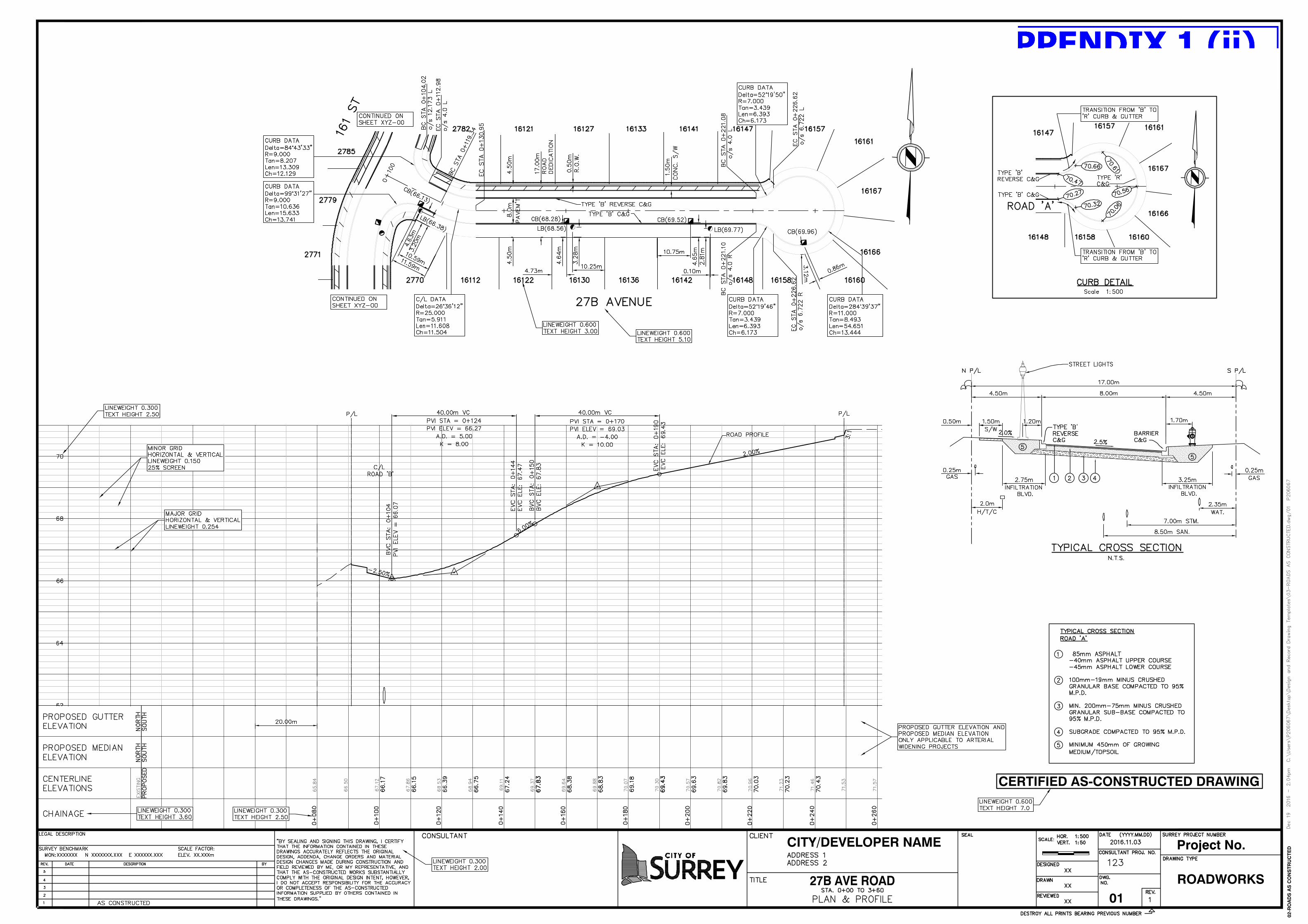
i. 27B Avenue Road – Design Template ii. 27B Avenue Road – As‐Constructed Template
Appendix 2: Utility Templates
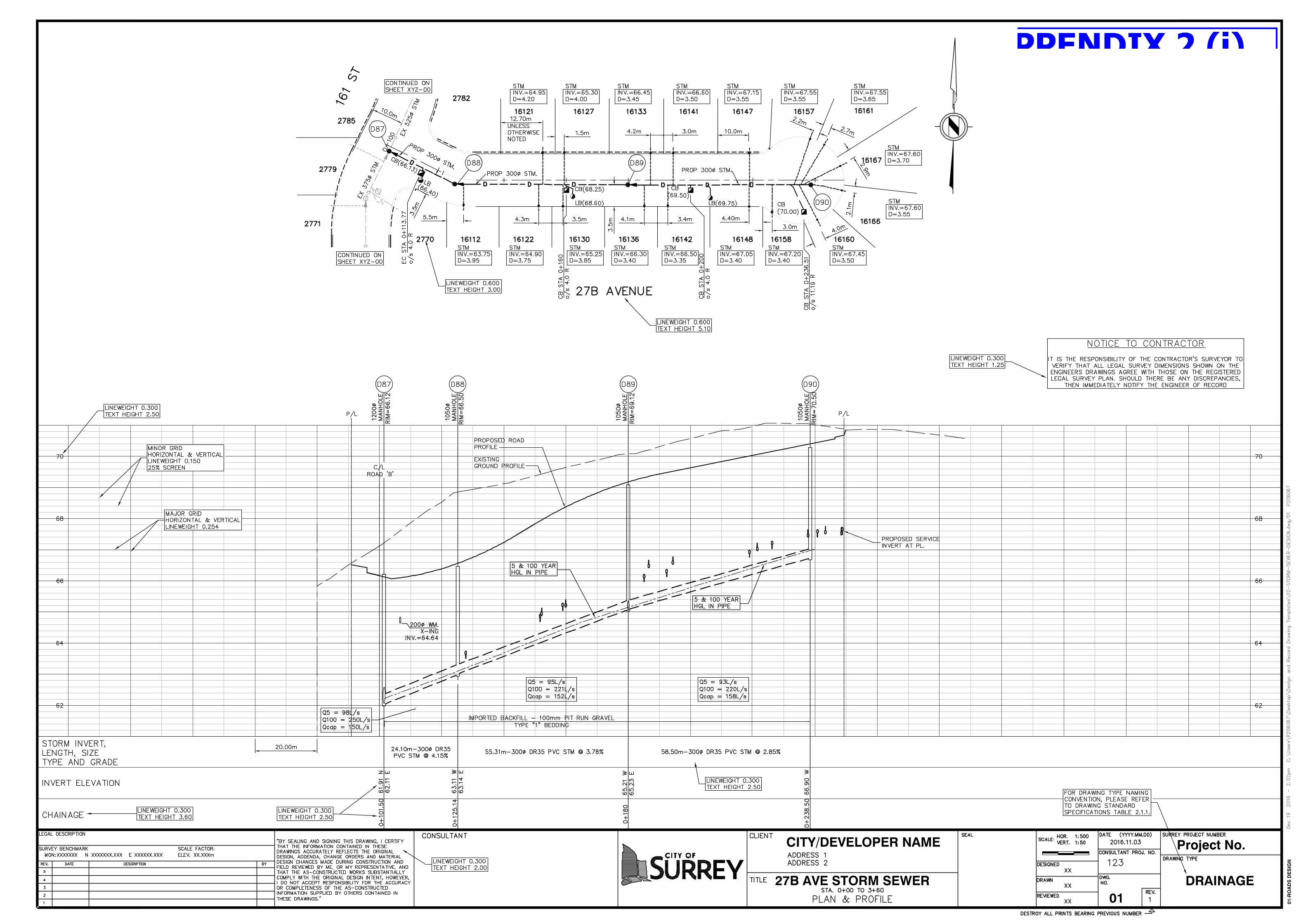
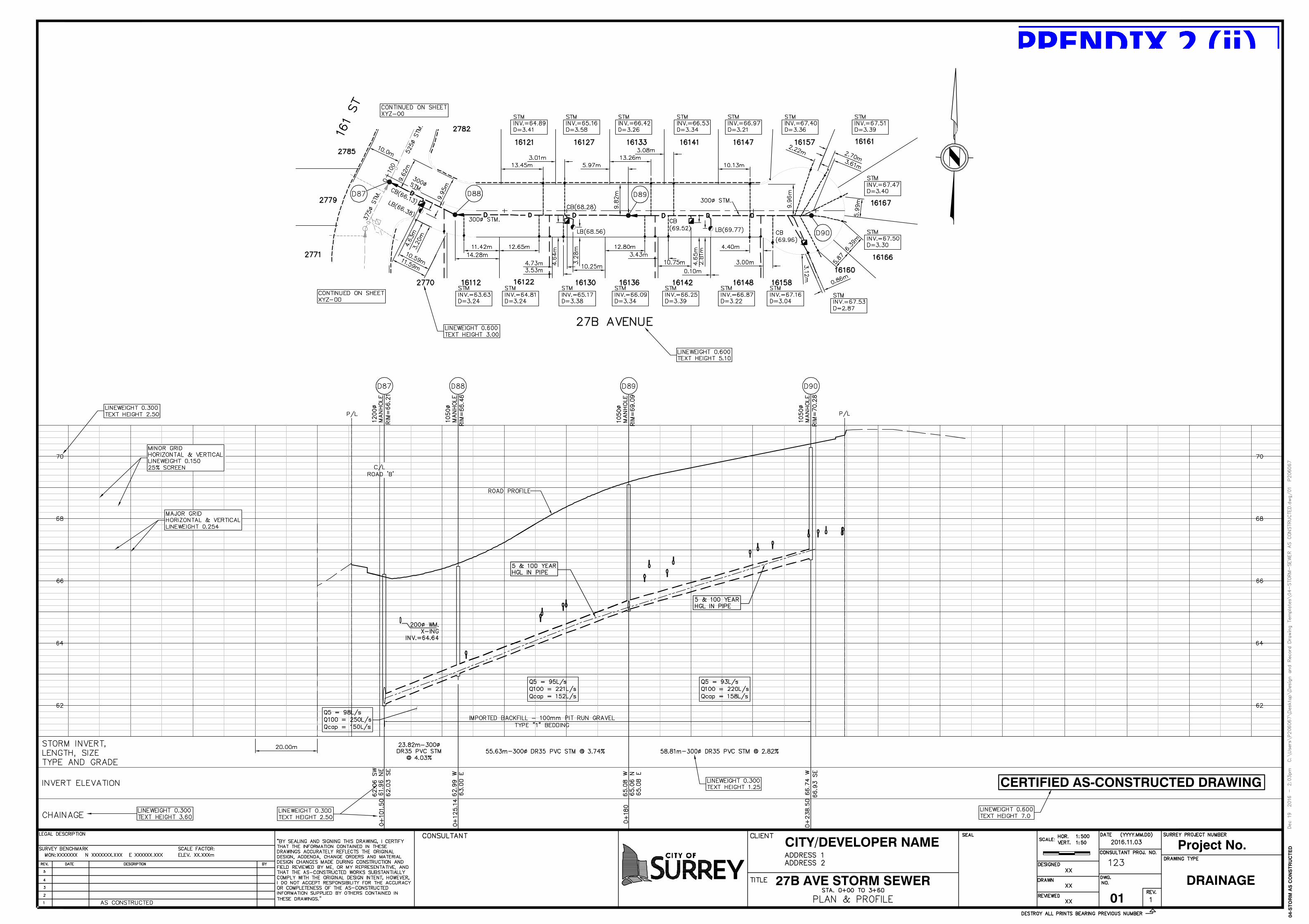
i. 27B Avenue Storm Sewer – Design Template ii. 27B Avenue Storm Sewer – As‐Constructed Template
Appendix 3: Legend & Linetypes
City of Surrey Page 1 Engineering Department Drawing Standard Specifications June 2017
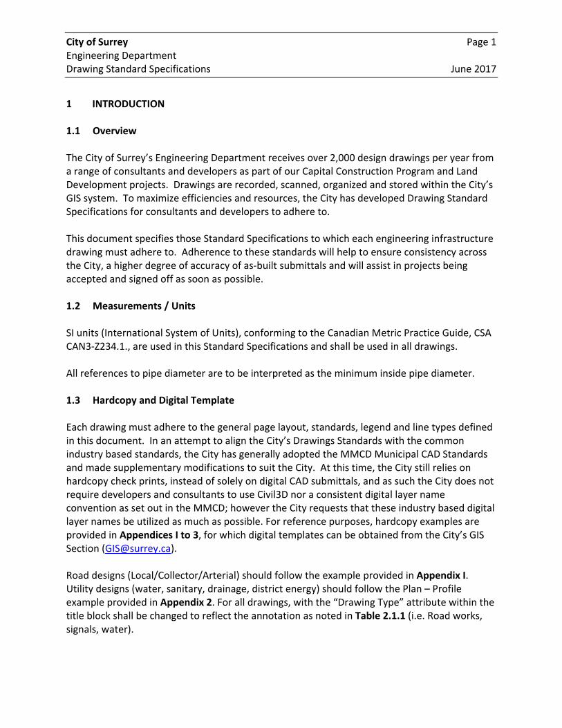
1 INTRODUCTION 1.1 Overview The City of Surrey’s Engineering Department receives over 2,000 design drawings per year from a range of consultants and developers as part of our Capital Construction Program and Land Development projects. Drawings are recorded, scanned, organized and stored within the City’s GIS system. To maximize efficiencies and resources, the City has developed Drawing Standard Specifications for consultants and developers to adhere to. This document specifies those Standard Specifications to which each engineering infrastructure drawing must adhere to. Adherence to these standards will help to ensure consistency across the City, a higher degree of accuracy of as‐built submittals and will assist in projects being accepted and signed off as soon as possible. 1.2 Measurements / Units SI units (International System of Units), conforming to the Canadian Metric Practice Guide, CSA CAN3‐Z234.1., are used in this Standard Specifications and shall be used in all drawings. All references to pipe diameter are to be interpreted as the minimum inside pipe diameter. 1.3 Hardcopy and Digital Template Each drawing must adhere to the general page layout, standards, legend and line types defined in this document. In an attempt to align the City’s Drawings Standards with the common industry based standards, the City has generally adopted the MMCD Municipal CAD Standards and made supplementary modifications to suit the City. At this time, the City still relies on hardcopy check prints, instead of solely on digital CAD submittals, and as such the City does not require developers and consultants to use Civil3D nor a consistent digital layer name convention as set out in the MMCD; however the City requests that these industry based digital layer names be utilized as much as possible. For reference purposes, hardcopy examples are provided in Appendices I to 3, for which digital templates can be obtained from the City’s GIS Section ([email protected]). Road designs (Local/Collector/Arterial) should follow the example provided in Appendix I. Utility designs (water, sanitary, drainage, district energy) should follow the Plan – Profile example provided in Appendix 2. For all drawings, with the “Drawing Type” attribute within the title block shall be changed to reflect the annotation as noted in Table 2.1.1 (i.e. Road works, signals, water).
City of Surrey Page 2 Engineering Department Drawing Standard Specifications June 2017
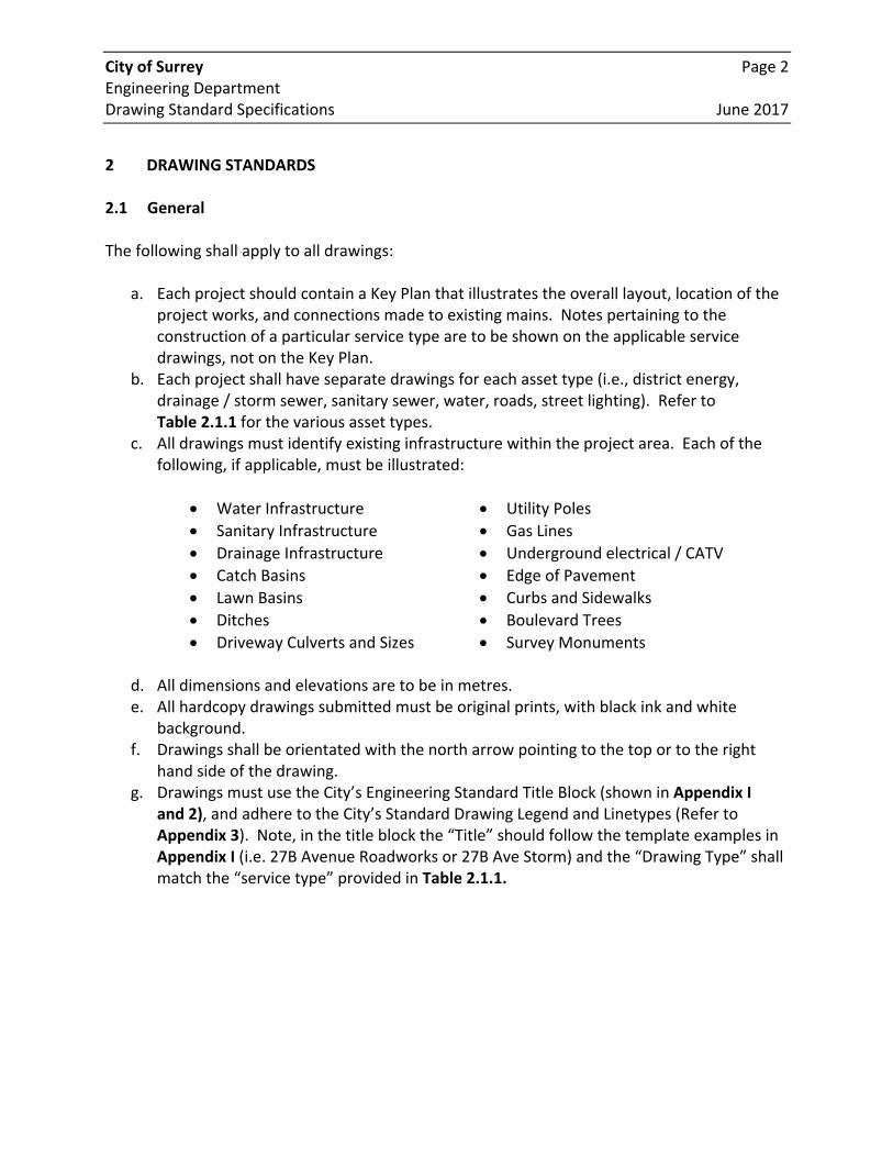
2 DRAWING STANDARDS 2.1 General The following shall apply to all drawings:
a. Each project should contain a Key Plan that illustrates the overall layout, location of the project works, and connections made to existing mains. Notes pertaining to the construction of a particular service type are to be shown on the applicable service drawings, not on the Key Plan.
b. Each project shall have separate drawings for each asset type (i.e., district energy, drainage / storm sewer, sanitary sewer, water, roads, street lighting). Refer to Table 2.1.1 for the various asset types.
c. All drawings must identify existing infrastructure within the project area. Each of the following, if applicable, must be illustrated:
Water Infrastructure Utility Poles
Sanitary Infrastructure Gas Lines
Drainage Infrastructure Underground electrical / CATV
Catch Basins Edge of Pavement
Lawn Basins Curbs and Sidewalks
Ditches Boulevard Trees
Driveway Culverts and Sizes Survey Monuments
d. All dimensions and elevations are to be in metres. e. All hardcopy drawings submitted must be original prints, with black ink and white
background. f. Drawings shall be orientated with the north arrow pointing to the top or to the right
hand side of the drawing. g. Drawings must use the City’s Engineering Standard Title Block (shown in Appendix I
and 2), and adhere to the City’s Standard Drawing Legend and Linetypes (Refer to Appendix 3). Note, in the title block the “Title” should follow the template examples in Appendix I (i.e. 27B Avenue Roadworks or 27B Ave Storm) and the “Drawing Type” shall match the “service type” provided in Table 2.1.1.
City of Surrey Page 3 Engineering Department Drawing Standard Specifications June 2017
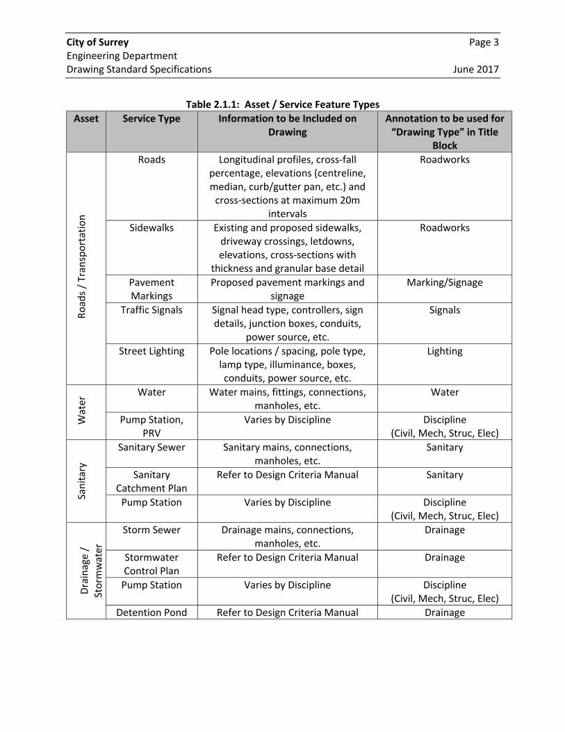
Table 2.1.1: Asset / Service Feature Types
Asset Service Type Information to be Included on Drawing
Annotation to be used for “Drawing Type” in Title
Block
Roads / Transportation
Roads Longitudinal profiles, cross‐fall percentage, elevations (centreline, median, curb/gutter pan, etc.) and cross‐sections at maximum 20m
intervals
Roadworks
Sidewalks Existing and proposed sidewalks, driveway crossings, letdowns, elevations, cross‐sections with
thickness and granular base detail
Roadworks
Pavement Markings
Proposed pavement markings and signage
Marking/Signage
Traffic Signals Signal head type, controllers, sign details, junction boxes, conduits,
power source, etc.
Signals
Street Lighting Pole locations / spacing, pole type, lamp type, illuminance, boxes, conduits, power source, etc.
Lighting
Water Water Water mains, fittings, connections,
manholes, etc. Water
Pump Station, PRV
Varies by Discipline Discipline (Civil, Mech, Struc, Elec)
Sanitary
Sanitary Sewer Sanitary mains, connections, manholes, etc.
Sanitary
Sanitary Catchment Plan
Refer to Design Criteria Manual Sanitary
Pump Station Varies by Discipline Discipline (Civil, Mech, Struc, Elec)
Drainage /
Storm
water
Storm Sewer Drainage mains, connections, manholes, etc.
Drainage
Stormwater Control Plan
Refer to Design Criteria Manual Drainage
Pump Station Varies by Discipline Discipline (Civil, Mech, Struc, Elec)
Detention Pond Refer to Design Criteria Manual Drainage
City of Surrey Page 4 Engineering Department Drawing Standard Specifications June 2017
2.2 Survey and Drawing Reference (Horizontal and Vertical Datums) The City of Surrey lies within Integrated Survey Area No.1, Surrey (ISA No.1) and is also covered by the Metro Vancouver Active Control System (MV‐ACS). All drawings submitted to the City must reference coordinates (eastings, northings, and elevations) derived from either:
1. Ties made to at least two existing and validated ISA No.1 integrated survey monuments shown in the Integrated Survey Area Listing issued September 29, 2010. Validation observations must be recorded and displayed on the Key Plan; or
2. Ties made to an active control base station within the MV‐ACS or any other Class A GNSS base stations validated and categorized by the Province. Observations to known ISA No.1 ground control monuments will be required to ensure adequate redundancy. These observations must be recorded and displayed on the Key Plan.
Coordinates derived from either of these methods will reflect the latest coordinate refresh published by the Province of BC using the Nad83 (CSRS) 4.0.0.BC.1.GVRD horizontal datum and CVD28GVRD vertical datum. After January 1, 2018, the vertical reference datum will be CGVD2013. Each drawing must include a reference to the survey control used and must include:
ISA No.1 Monument number or name of the MV‐ACS or Class A Base Stations;
Coordinates (eastings, northings, and elevations); and
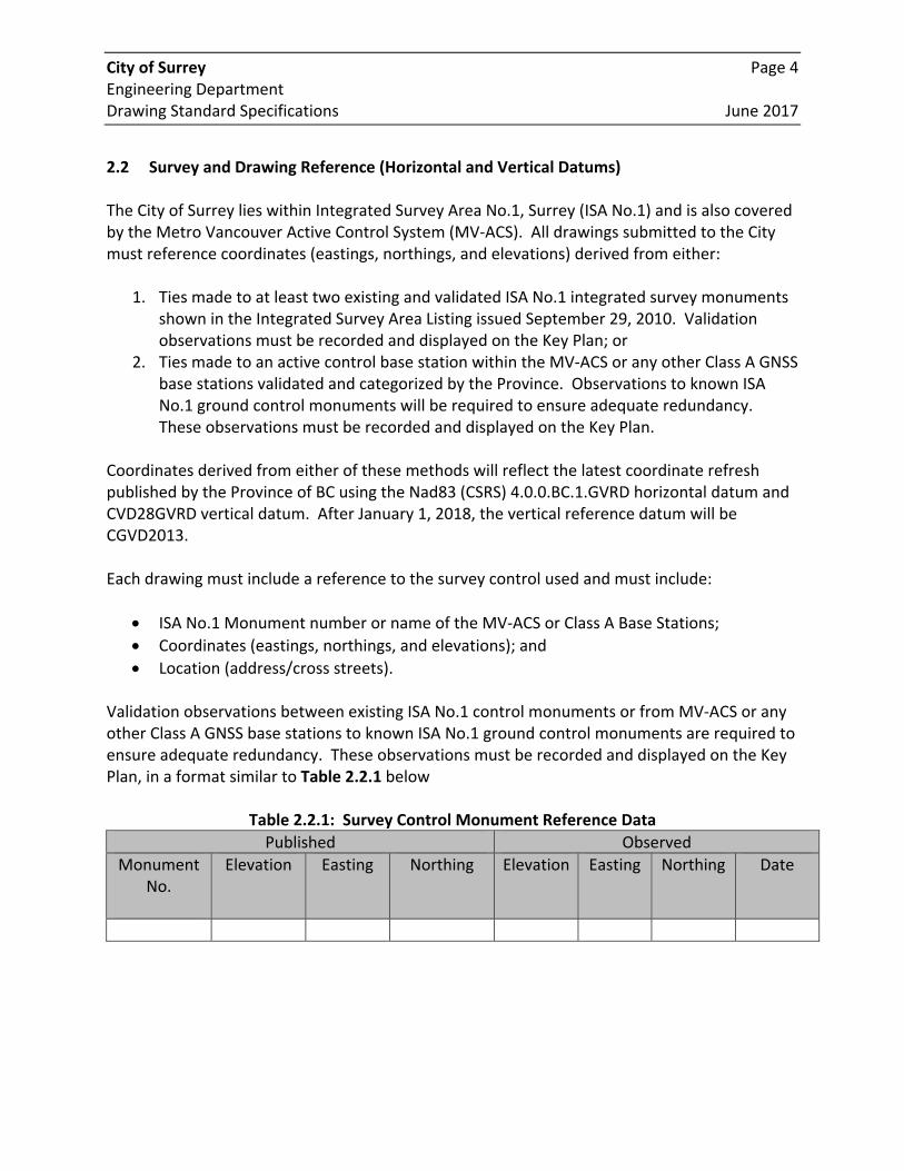
Location (address/cross streets). Validation observations between existing ISA No.1 control monuments or from MV‐ACS or any other Class A GNSS base stations to known ISA No.1 ground control monuments are required to ensure adequate redundancy. These observations must be recorded and displayed on the Key Plan, in a format similar to Table 2.2.1 below
Table 2.2.1: Survey Control Monument Reference Data
Published Observed
Monument No.
Elevation Easting Northing Elevation Easting Northing Date
City of Surrey Page 5 Engineering Department Drawing Standard Specifications June 2017
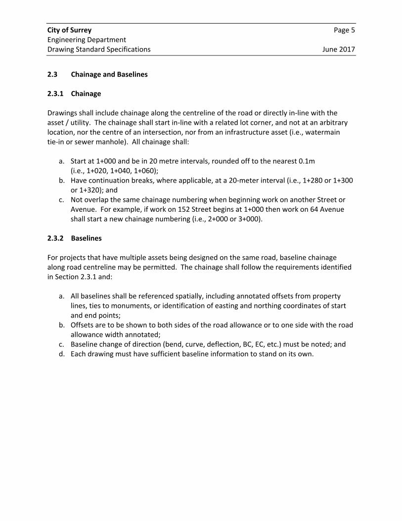
2.3 Chainage and Baselines 2.3.1 Chainage Drawings shall include chainage along the centreline of the road or directly in‐line with the asset / utility. The chainage shall start in‐line with a related lot corner, and not at an arbitrary location, nor the centre of an intersection, nor from an infrastructure asset (i.e., watermain tie‐in or sewer manhole). All chainage shall:
a. Start at 1+000 and be in 20 metre intervals, rounded off to the nearest 0.1m (i.e., 1+020, 1+040, 1+060);
b. Have continuation breaks, where applicable, at a 20‐meter interval (i.e., 1+280 or 1+300 or 1+320); and
c. Not overlap the same chainage numbering when beginning work on another Street or Avenue. For example, if work on 152 Street begins at 1+000 then work on 64 Avenue shall start a new chainage numbering (i.e., 2+000 or 3+000).
2.3.2 Baselines For projects that have multiple assets being designed on the same road, baseline chainage along road centreline may be permitted. The chainage shall follow the requirements identified in Section 2.3.1 and:
a. All baselines shall be referenced spatially, including annotated offsets from property lines, ties to monuments, or identification of easting and northing coordinates of start and end points;
b. Offsets are to be shown to both sides of the road allowance or to one side with the road allowance width annotated;
c. Baseline change of direction (bend, curve, deflection, BC, EC, etc.) must be noted; and d. Each drawing must have sufficient baseline information to stand on its own.
City of Surrey Page 6 Engineering Department Drawing Standard Specifications June 2017
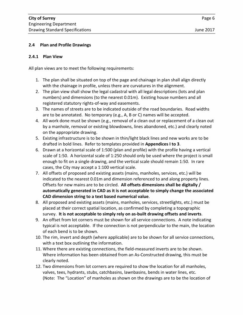
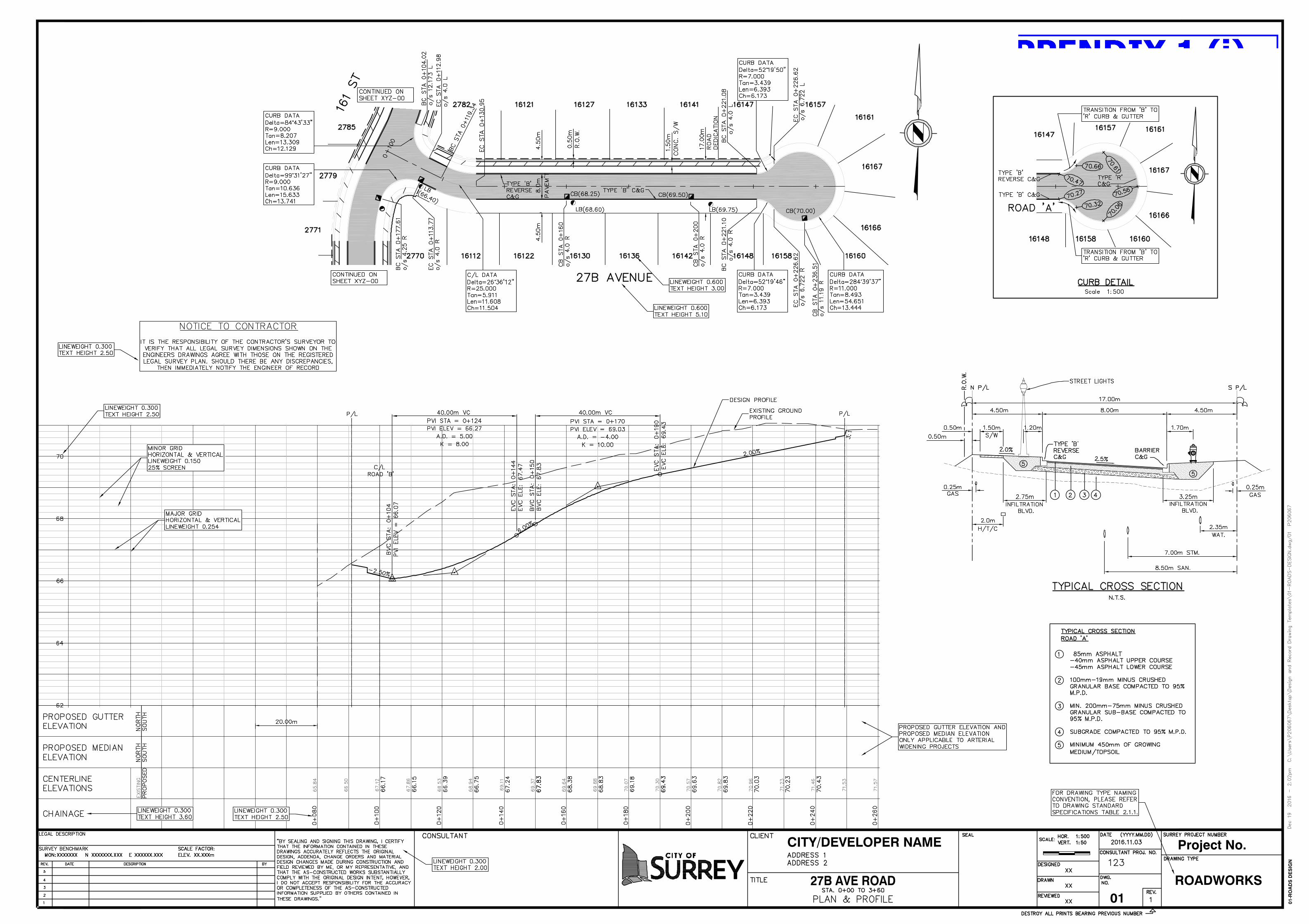
2.4 Plan and Profile Drawings 2.4.1 Plan View All plan views are to meet the following requirements:
1. The plan shall be situated on top of the page and chainage in plan shall align directly with the chainage in profile, unless there are curvatures in the alignment.
2. The plan view shall show the legal cadastral with all legal descriptions (lots and plan numbers) and dimensions (to the nearest 0.01m). Existing house numbers and all registered statutory rights‐of‐way and easements.
3. The names of streets are to be indicated outside of the road boundaries. Road widths are to be annotated. No temporary (e.g., A, B or C) names will be accepted.
4. All work done must be shown (e.g., removal of a clean out or replacement of a clean out by a manhole, removal or existing blowdowns, lines abandoned, etc.) and clearly noted on the appropriate drawing.
5. Existing infrastructure is to be shown in thin/light black lines and new works are to be drafted in bold lines. Refer to templates provided in Appendices I to 3.
6. Drawn at a horizontal scale of 1:500 (plan and profile) with the profile having a vertical scale of 1:50. A horizontal scale of 1:250 should only be used where the project is small enough to fit on a single drawing, and the vertical scale should remain 1:50. In rare cases, the City may accept a 1:100 vertical scale.
7. All offsets of proposed and existing assets (mains, manholes, services, etc.) will be indicated to the nearest 0.01m and dimension referenced to and along property lines. Offsets for new mains are to be circled. All offsets dimensions shall be digitally / automatically generated in CAD as it is not acceptable to simply change the associated CAD dimension string to a text based numerical value.
8. All proposed and existing assets (mains, manholes, services, streetlights, etc.) must be placed at their correct spatial location, as confirmed by completing a topographic survey. It is not acceptable to simply rely on as‐built drawing offsets and inverts.
9. An offset from lot corners must be shown for all service connections. A note indicating typical is not acceptable. If the connection is not perpendicular to the main, the location of each bend is to be shown.
10. The rim, invert and depth (where applicable) are to be shown for all service connections, with a text box outlining the information.
11. Where there are existing connections, the field‐measured inverts are to be shown. Where information has been obtained from an As‐Constructed drawing, this must be clearly noted.
12. Two dimensions from lot corners are required to show the location for all manholes, valves, tees, hydrants, stubs, catchbasins, lawnbasins, bends in water lines, etc. (Note: The “Location” of manholes as shown on the drawings are to be the location of
City of Surrey Page 7 Engineering Department Drawing Standard Specifications June 2017
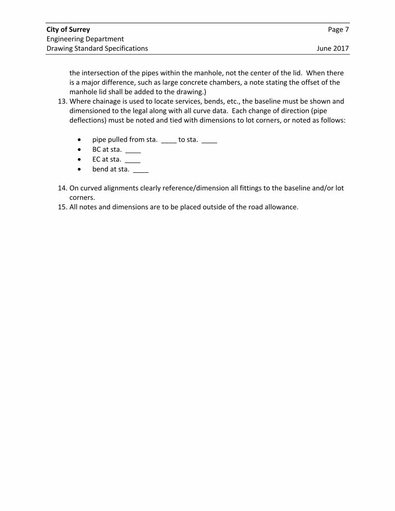
the intersection of the pipes within the manhole, not the center of the lid. When there is a major difference, such as large concrete chambers, a note stating the offset of the manhole lid shall be added to the drawing.)
13. Where chainage is used to locate services, bends, etc., the baseline must be shown and dimensioned to the legal along with all curve data. Each change of direction (pipe deflections) must be noted and tied with dimensions to lot corners, or noted as follows:
pipe pulled from sta. ____ to sta. ____
BC at sta. ____
EC at sta. ____
bend at sta. ____
14. On curved alignments clearly reference/dimension all fittings to the baseline and/or lot corners.
15. All notes and dimensions are to be placed outside of the road allowance.
City of Surrey Page 8 Engineering Department Drawing Standard Specifications June 2017
2.4.2 Profile View Profile views on drawings are to meet the following requirements:
1. The profile view must show:
Chainages and profile along the baseline;
Elevations of new and existing works;
New and existing service connections (all asset types);
Mains and services being crossed by the new works (and their elevations);
All data pertaining to the design of the works; and
Major and minor grid, as per the Drawing Templates provided in Appendix I and 2.
2. Elevations at all grade changes are to be shown with a chainage or ties to lot corners. 3. All elevations are to be geodetic. Existing elevations are to be rounded to the nearest
0.01m whereas proposed elevations are to be rounded to nearest 0.001m. 4. Start chainage on the profile view, should line up vertically with the station on the plan
view. 5. The material type (PVC, concrete, etc.) and DR (or pressure rating) must be shown on
the profile for all mains. 6. Rim and invert elevations are required for all manholes and clean outs. 7. All manhole and clean‐out diameter are to be noted. If a standard 1,050 mm diameter
manhole is used, a general note is acceptable with any non‐standard diameters clearly noted on the profile.
8. Profiles must be shown for all utility/asset designs (including road crossings) except where the installation of connections from an existing main is the only work performed.
9. Pipe measurements should be from the center of each associated manhole. Chainage distances are not acceptable.
10. For drop manholes, the type of drop (‘inside’, ‘outside’ or ‘ramp’ manhole) must be noted, along with the associated inverts of each manhole penetration.
11. Where a new main connects to an existing main, show the location and inverts of both existing upstream and downstream manholes.
City of Surrey Page 9 Engineering Department Drawing Standard Specifications June 2017
2.5 Additional Standards for Specific Service Drawings This section details standards specific to individual service drawings (as previously identified in Table 2.1.1). All Specific Service Drawings shall conform to the City of Surrey Standard Drawing Templates. 2.5.1 Storm and Sanitary Sewers Additional information required on storm and sanitary sewer drawings includes:
1. Sewer diameter and material and manhole diameter and material are to be shown, as well as all invert and service elevations.
2. Where a new sewer ties to an existing stub, the balance of the distance to the existing manhole (from the new sewer) is to be shown.
3. Show location, invert and offset all new sewers installed, regardless of length. 4. All lawn basins (both private and Municipal) are to be referenced to lot corners and the
size, material and rim elevation shown with the size and material of the lead. 5. 5 and 100‐year HGL (storm) is to be shown. For each proposed storm sewer pipe, the
Q5, Q100 and QC will be noted in the profile. 6. All sanitary sewer flows and capacity to be shown in profile for each section of pipe. 7. The type of backfill material is to be shown on each drawing. If sections of the sewers
require non‐standard backfill (i.e., lightweight fill), the extent of that backfill must be shown both vertically and horizontally in the plan‐profile.
8. Storm sewer catch basin locations and rim elevations are to be shown, with the offset from property line to the back of catch basin and the chainage.
9. Detention pond information required:
Stage‐storage curve, with elevations;
All pipes with diameters, inverts and location;
Design water levels, high water elevation, and orifice/weir elevations;
Control device(s) and maintenance details; and
Location, size and elevation of all manholes, catchbasins, etc.
10. Service connections to be dimensioned with references to property line. 11. All non‐standard service connections are to be noted on the drawing.
City of Surrey Page 10 Engineering Department Drawing Standard Specifications June 2017
2.5.2 Roads Additional information required on road drawings includes:
1. A typical cross‐section of the designed roads is to be shown on each drawing. 2. Pavement tapers are to be dimensioned to property lines with length of taper
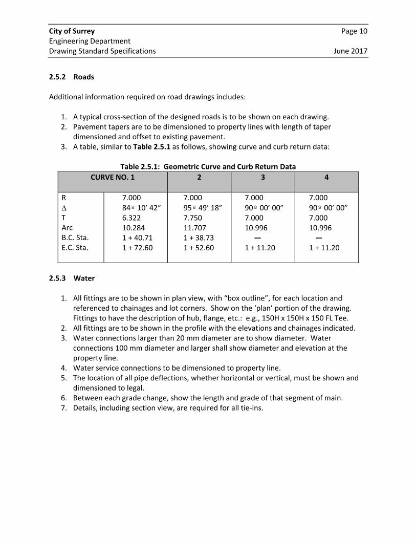
dimensioned and offset to existing pavement. 3. A table, similar to Table 2.5.1 as follows, showing curve and curb return data:
Table 2.5.1: Geometric Curve and Curb Return Data
2.5.3 Water
1. All fittings are to be shown in plan view, with “box outline”, for each location and referenced to chainages and lot corners. Show on the ‘plan’ portion of the drawing. Fittings to have the description of hub, flange, etc.: e.g., 150H x 150H x 150 FL Tee.
2. All fittings are to be shown in the profile with the elevations and chainages indicated. 3. Water connections larger than 20 mm diameter are to show diameter. Water
connections 100 mm diameter and larger shall show diameter and elevation at the property line.
4. Water service connections to be dimensioned to property line. 5. The location of all pipe deflections, whether horizontal or vertical, must be shown and
dimensioned to legal. 6. Between each grade change, show the length and grade of that segment of main. 7. Details, including section view, are required for all tie‐ins.
CURVE NO. 1
2 3 4
R
T Arc B.C. Sta. E.C. Sta.
7.000 84º 10’ 42” 6.322 10.284 1 + 40.71 1 + 72.60
7.000 95º 49’ 18” 7.750 11.707 1 + 38.73 1 + 52.60
7.000 90º 00’ 00” 7.000 10.996
— 1 + 11.20
7.000 90º 00’ 00” 7.000 10.996 —
1 + 11.20
City of Surrey Page 11 Engineering Department Drawing Standard Specifications June 2017
2.5.4 Street Light Works
1. The drawings will only include plan views. Profile not required. All improvements (service boxes, poles, etc.) are to be tied to property lines.
2. Streetlights are to be numbered in accordance with the City’s procedures.
2.5.5 Sidewalks The drawings must show the width of the sidewalk and the type of materials used. The offset to back of the sidewalk are to be dimensioned to the property line must be circled. A typical cross‐section shall also be shown on each drawing; see next section.
1. When sidewalks are part of road works, they will be shown on road drawings. 2. When sidewalks are shown separately, the drawings will include plan view and profile. 3. The drawings will require the same information as for streetlight works. The new
sidewalk will be drafted in bold lines and hatched (refer to line types in Appendix 3). 2.5.6 Cross‐Sections Cross‐sections are required for drawings depicting new road, sidewalk, drainage channels and/or dykes, and at least every 20m intervals. For road works, cross‐sections must span the full width of the road allowance and any tapers into private property. The cross‐section must include property lines, ditches, and edges of existing road and centreline of road. It must also illustrate chainages and elevations of each break in the cross‐section. The new road works must be shown with bold lines that emphasize the finished surface. Elevations of the new road must be shown. Road measurements from centreline of the road allowance must also be illustrated. Cross‐sections will be drafted using a 1:100 Horizontal Scale and a 1:20 Vertical Scale. Existing elevations in cross‐section should be rounded off to the nearest 0.01m, whereas proposed elevations in cross‐section should be bold text and rounded to the nearest 0.001m.
City of Surrey Page 12 Engineering Department Drawing Standard Specifications June 2017
2.5.7 Intersections
1. For road intersections with traffic signals or traffic channelization, the drawings will only include plan views. No profile is required. The scale of drawings must be 1:200.
2. The drawings will show the following existing services:
Curbs Hydrants
Sidewalks Edges of Pavement
Utility Poles Catch Basins
Islands Electrical Conduits and Junction Boxes
Valves Traffic Signals
Inspection Chambers
3. Conduits to be sized in millimetres. 4. The location of new lights, junction boxes, and conduits will be referenced to property
lines and circled. 5. Where traffic channelization is shown, widths of traffic lanes are to be shown, length of
road tapering and stop bars are to be shown. 6. Where raised islands are used, curb return details and a cross‐section of the intersection
is to be shown on the drawing, to scale.
City of Surrey Page 13 Engineering Department Drawing Standard Specifications June 2017
3 DRAWING SUBMISSION PROCESS 3.1 Submission Process Drawings must be submitted to the City’s GIS Section three times over the course of a typical project: (1) at the Final Design (Early Copy) stage, (2) the Initial As‐Constructed Submission stage, and (3) at the Final As‐Constructed submission stage. Only after the GIS Section processes and signs off on all drawings will the project obtain a letter of acceptance. Final Design / Issued for Construction Submission: The first time drawings are submitted to the City’ GIS Section is at the Final Design / Issued for Construction Stage, referred to by City as the Early Copy stage. One set of hard copy drawings and one set of digital AutoCAD files are required. For City Capital Projects, along with this submission, the consultant shall submit a compiled PDF of all drawings as well as the digital Survey file. Initial As‐Constructed Submission (Check Prints): Once construction is complete, one set of hardcopy drawings and the associated digital files must be sent to the City. Upon receipt, the City forwards the drawings to the GIS Section for input into the GIS database. The GIS Section records the receipt of the drawings, assigns Surrey Drawing Numbers, reviews the drawings for completeness and adherence to standards, and inputs all new services into the City’s GIS. Any deviation from standards, omissions, or any other deficiencies to the drawings will be noted and drawings will be returned to the consultant for final review and updates. The City expects all deficiencies to be corrected, and the Surrey Drawing Numbers entered on each drawing. Once complete, the drawings must be sent back to the City for final acceptance. Please note that the most frequent deficiency encountered involves the placement of features and the dimensions and offset distances associated with those features. Placement of features must be geographically correct. Any dimensions or offset distances displayed must be to scale (e.g., if the offset distance of a manhole from a lot corner is listed as 2.1m, the placement of the manhole symbol in CAD must be 2.1m from the lot corner). Simply changing the offset dimension text / label without moving the service feature accordingly is NOT acceptable. An initial set of As‐Constructed drawings must be submitted to the City Project Supervisor or Inspector within sixty (60) days of Substantial Completion or the issued date on the Letter of Completion.
City of Surrey Page 14 Engineering Department Drawing Standard Specifications June 2017
Final As‐Constructed Submission: The Final Submission is reviewed to ensure all corrections have been made appropriately. If so, the drawings are scanned and stored on the City’s network. A final acceptance letter is produced and sent to the consultant along with the release of any remaining security funds held back pending final acceptance. If drawings still have deficiencies, they are again returned to the consultant for corrections. Each submission package must contain one set of signed and sealed hard copy drawings and one digital file (AutoCAD‐Etransmit), which must include all files pertaining to the project. Final As‐Constructed submissions shall include the original marked‐up set of paper prints. Each set of hard copy drawings must include a Key Plan drawing and a separate drawing for each applicable service type (see Table 2.1.1). For City Capital Projects, the consultant shall submit a compiled PDF of all drawings. Please see Section 2 for a detailed description of all drawing standards. While the City recognizes the use of Civil3D, currently the digital file must either be in standard AutoCAD format, version 2010 or later. Please see Section 4 for additional information related to the digital submission. Notes:
1. Drawings with incomplete, non‐standard or confusing information will be returned for correction and/or clarification.
2. All drawings submitted remain the property of the City. 3. Final As‐Constructed drawings are to be returned to the City within 30 days after receipt
of the City’s Comments on the initial As‐Constructed Drawings/Check‐Prints. 3.2 Sign and Seal For all City Capital Projects, all drawings must be signed and sealed at specific milestones of a project: Final Design, Issued for Construction, and As‐Constructed. For Land Development Projects, all drawing submittals must be signed and sealed. The City requires As‐Constructed drawings be sign and sealed by a Professional Engineer registered, and in good standing, with the Association of Professional Engineers and Geoscientists of British Columbia (APEGBC).
City of Surrey Page 15 Engineering Department Drawing Standard Specifications June 2017
The City will not accept drawings titled Record Drawings, nor will the City will accept As‐Constructed drawings with disclaimers, with exception to the following disclaimer which the City has vetted through APEGBC and Legal Counsel:
“By sealing and signing this drawing, I certify that the information contained in these drawings accurately reflects the original design, addenda, change orders and material design changes made during construction and field reviewed by me, or my representative, and that the as‐constructed works substantially comply with the original design intent, however, I do not accept responsibility for the accuracy or completeness of the as‐constructed information supplied by others contained in these drawings.”
The above certification is based on the construction contractor providing As‐Constructed information to the Professional Engineer, and is not intended to restrict the Engineer from carrying out their professional requirements, due diligence and a proper standard of care, nor does it release the professional, or their representative, from not recording As‐Constructed information directly and in an accurate manner. Any, and all, quality assurance surveys completed by the developer, consultant or the contractor are to be conducted under the Professional Engineer’s supervision and the named firm may either be a sub‐consultant to the Professional Engineer or the firm the Professional Engineer is employed by, where qualified survey staff are available. The Professional Engineer must sign and seal the Final As‐Constructed drawings submitted to the City.
City of Surrey Page 16 Engineering Department Drawing Standard Specifications June 2017
4 DIGITAL FILE SUBMISSION A digital file must be included with the submission of the hard copy drawing set at each stage as noted above in Section 3.1. The digital file submitted must adhere to the following general requirements:
Must conform to the City of Surrey Standard Drawing Templates;
Must be AutoCAD (version 2010 or later);
Must conform to the City’s GIS spatial coordinate system (UTM Zone 10, NAD83 (CSRS) 4.0.0.BC.1.GVRD_2005‐04‐05). Ground measurements must be properly scaled to grid measurements. (Section 4.1);
Must be one comprehensive file, included with each submission. File name must adhere to file naming conventions (Section 4.2); and
Can be emailed or copied to a CD/USB drive and attached with the hard copy submissions (Section 4.3).
4.1 Spatial Coordinate System Note that the City’s GIS system stores all existing legal and utility data in UTM, Zone 10, NAD83 (CSRS) 4.0.0.BC.1.GVRD_2005‐04‐05 coordinate system. The City requires submitted digital files be in this coordinate system as well. This coordinate (or reference) system is a GRID based system. If your file is in a local, ground based coordinate system (i.e., ground measurements) then you must convert it to our grid based coordinate system prior to submission. You must use a mean combined scale factor for the project area when converting from GROUND to GRID. Scale factor computation software and scale factor gradient (contour) maps will be provided to consultants upon request. 4.2 Naming Convention for Digital File Digital files submitted to the City will be copied to a common network directory for processing. File naming conventions must be followed to ensure proper organization. The naming conventions for these files include the Surrey project number and the submission phase (EC, Initial As‐Constructed, and Final As‐Constructed). That is, the file name should follow this convention: City‐Project‐Number_Phase.dwg
City of Surrey Page 17 Engineering Department Drawing Standard Specifications June 2017
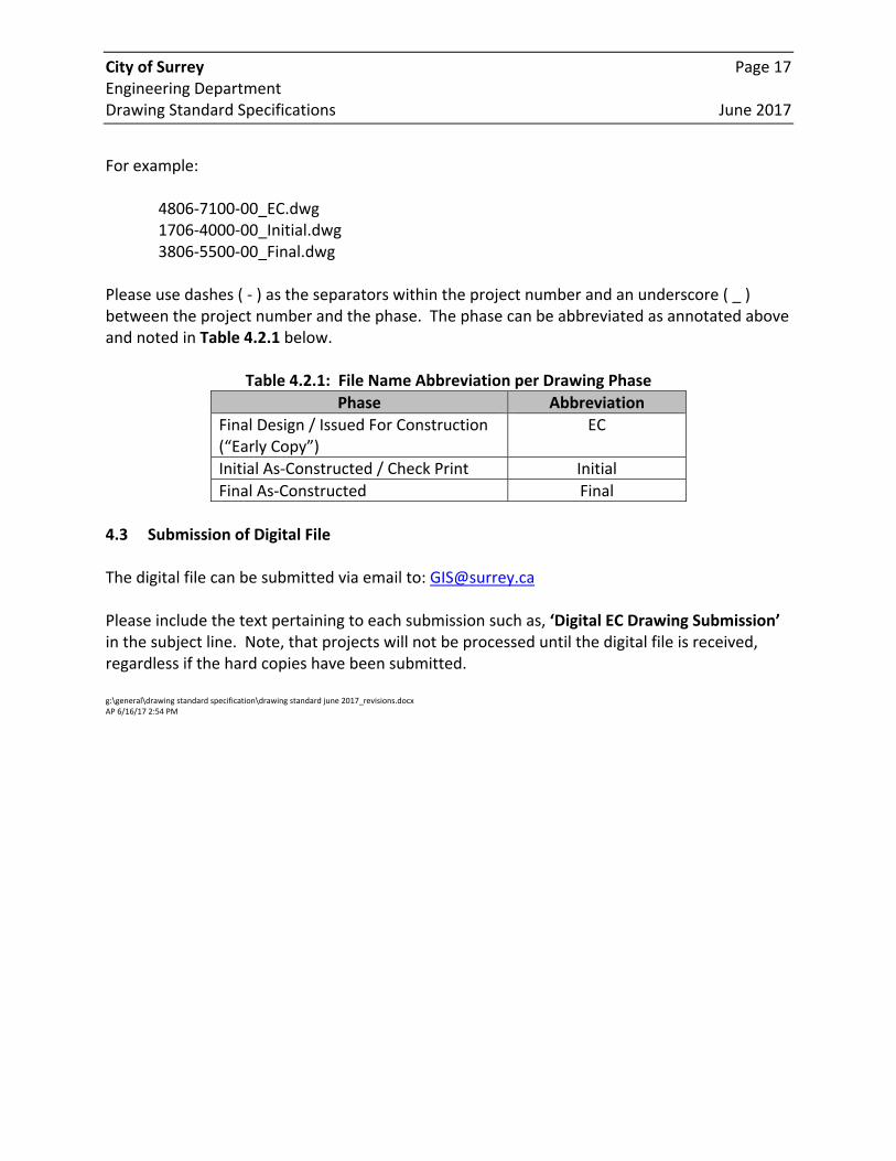
For example: 4806‐7100‐00_EC.dwg 1706‐4000‐00_Initial.dwg 3806‐5500‐00_Final.dwg Please use dashes ( ‐ ) as the separators within the project number and an underscore ( _ ) between the project number and the phase. The phase can be abbreviated as annotated above and noted in Table 4.2.1 below.
Table 4.2.1: File Name Abbreviation per Drawing Phase
Phase Abbreviation
Final Design / Issued For Construction (“Early Copy”)
EC
Initial As‐Constructed / Check Print Initial
Final As‐Constructed Final
4.3 Submission of Digital File The digital file can be submitted via email to: [email protected] Please include the text pertaining to each submission such as, ‘Digital EC Drawing Submission’ in the subject line. Note, that projects will not be processed until the digital file is received, regardless if the hard copies have been submitted. g:\general\drawing standard specification\drawing standard june 2017_revisions.docx AP 6/16/17 2:54 PM
APPENDIX I ‐ ROAD TEMPLATES
i. 27B Avenue Road ‐ Design Template ii. 27B Avenue Road – As‐Constructed Template
01-R
OA
DS
DE
SIG
N
CITY/DEVELOPER NAME
ROADWORKS
Project No.
0127B AVE ROAD
02-R
OA
DS
AS
CO
NS
TRU
CTE
D
CITY/DEVELOPER NAME
ROADWORKS
Project No.
0127B AVE ROAD
CERTIFIED AS-CONSTRUCTED DRAWING
APPENDIX 2 ‐ UTILITY TEMPLATES
i. 27B Avenue Storm Sewer ‐ Design Template ii. 27B Avenue Storm Sewer – As‐Constructed Template
01-R
OA
DS
DE
SIG
N
CITY/DEVELOPER NAME
DRAINAGE
Project No.
0127B AVE STORM SEWER
04-S
TOR
M A
S C
ON
STR
UC
TEDCITY/DEVELOPER NAME
DRAINAGE
Project No.
0127B AVE STORM SEWER
CERTIFIED AS-CONSTRUCTED DRAWING
APPENDIX 3 – LEGEND & LINETYPES
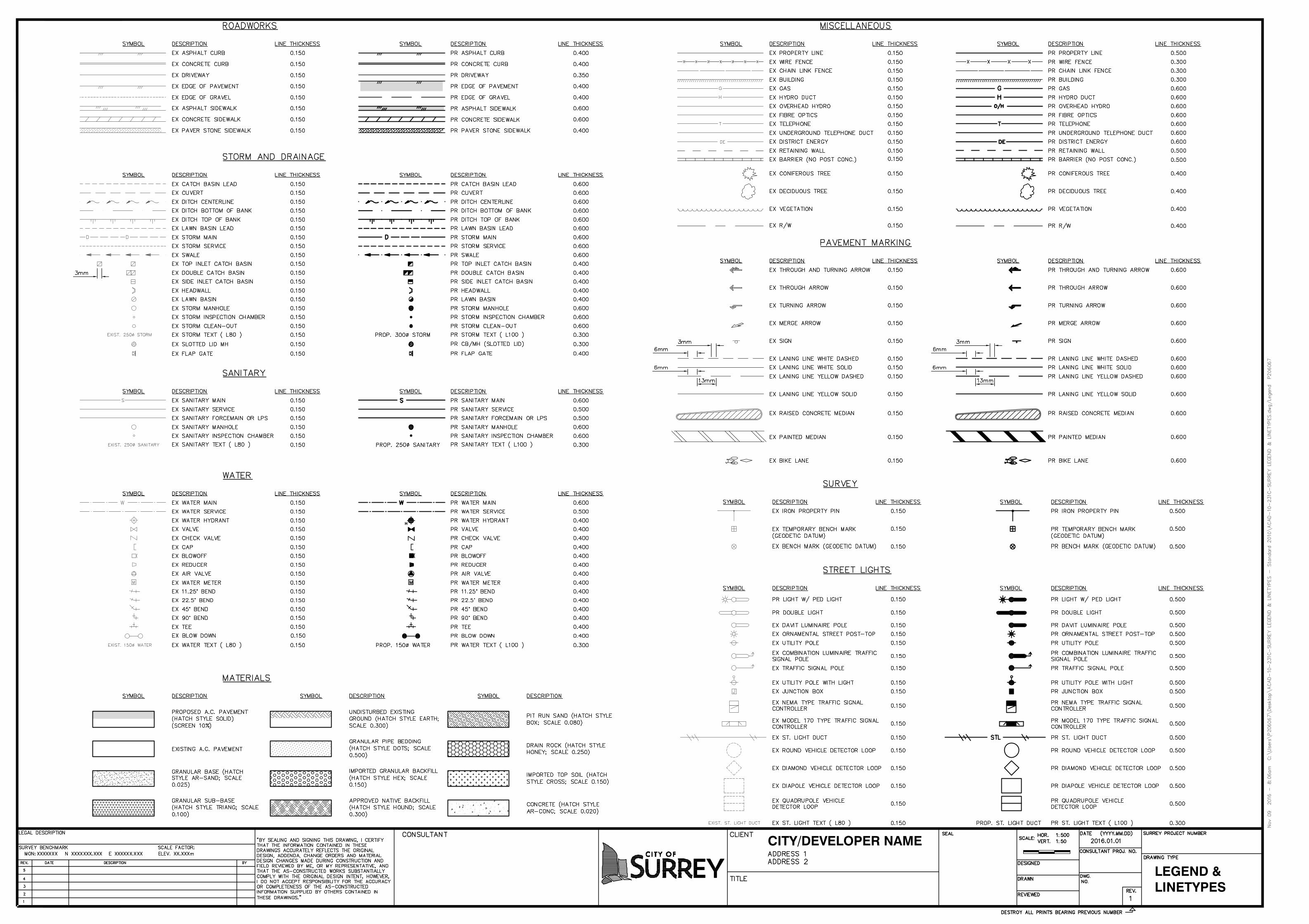
CITY/DEVELOPER NAME
LEGEND &LINETYPES
Recommended