04.2017
WK 430 700
Type WMM10/WMD10/WMR10/WH10 WK 430 700 04.2017
dm /min3
- 1 -
TTTT TTTTPPPPAAAA BBBB
PPPP
4WMM10 E - 62/...
1243 56 7
4WMM10 E - 62/FFFF... 4WMM10 E - 62/...B.B.B.B...
up to 35 MPa up to 160NS10
Directional spool valve - hand lever operated
type WMM10
Directional spool valve types
WMM10 hand lever operated
WMD10 rotary knob operated
WMR10 roller operated
WH10 hydraulically operated
General information
APPLICATION
DESCRIPTION OF OPERATION
Directional spool valves can be made in differently
operated design versions:
• hand lever operated type WMMWMMWMMWMM10101010
• rotary knob operated type WMDWMDWMDWMD10101010
• roller operated type WMRWMRWMRWMR10101010
• hydraulically operated type WHWHWHWH10101010
The directional valves are intended for subplate
mounting in any position in hydraulic system.
Main bore and annular ports PPPP, TTTT, AAAA, BBBB are made in
the housing (1) and connected to its subplate
connection. Directional valve is switched by shifting
the spool (2) into one end position. Various control
functions result from the shape of control spool (2)
which affects the change in configuration of the
connections between ports PPPP, TTTT, A A A A and BBBB in the
housing (1).
The spool (2) is shifted by changing the position of
hand lever (3) by means of the pin (4). The spool
return (2) to its rest position is secured by centering
springs (5) - version WMM10…/… . Positions of the
spool can be fixed by means of the detent (6) as well -
version …WMM10…/FFFF. Directional spool valve may
be provided with the orifice (7) placed in port PPPP -
version …WMM10…/…BBBB.
Directional spool valves are intended for change in
direction of fluid flow in a hydraulic system and thus it
allows to change direction of movement of a receiver
- mostly piston rod of a cylinder or hydraulic motor
as well to use functions: on and off.
DDDDAAAATTTTAAAA SSSSHHHHEEEEEEEETTTT ---- OOOOPPPPEEEERARARARATTTTIIIIOOOON N N N MAMAMAMANUANUANUANUALLLL
Type WMM10/WMD10/WMR10/WH10WK 430 700 04.2017
4WMD10 E - 62/FFFF...
4WMR10 E - 62/...
TTTT TTTTPPPPAAAA BBBB
PPPP
TTTT TTTTPPPPAAAA BBBB
PPPP
TTTT TTTTPPPPAAAA BBBB
PPPP
23 5 16 4
4 3 15 6
3 4 25 1
4WH10 E - 62/...
- 2 -
8
6
4WH10 E - 62/...BBBB...
4WMD10 E - 62/FBBBB...
4WMR10 E - 62/...B...B...B...B...
7
7
7
2
Directional spool valve - roller operated
type WMR10
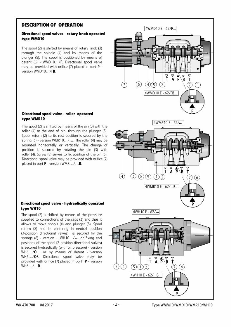
Directional spool valve - hydraulically operated
type WH10
Directional spool valves - rotary knob operated
type WMD10
The spool (2) is shifted by means of rotary knob (3)
through the spindle (4) and by means of the
plunger (5). The spool is positioned by means of
detent (6) - WMD10…/FFFF. Directional spool valve
may be provided with orifice (7) placed in port PPPP -
version WMD10…/FBBBB.
The spool (2) is shifted by means of the pin (3) with the
roller (4) at the end of pin, through the plunger (5).
Spool return (2) to its rest position is secured by the
spring (6) - version WMR10…/…. The roller (4) may be
mounted horizontally or vertically. The change of
position is secured by rotating the pin (3) with
roller (4). Screw (8) serves to fix position of the pin (3).
Directional spool valve may be provided with orifice (7)
placed in port PPPP - version WMR…/…BBBB.
The spool (2) is shifted by means of the pressure
supplied to connections of the caps (3) and thus it
allows to move spools (4) and plunger (5). Spool
return (2) and its centering in neutral position
(3-position directional valves) is secured by the
springs (6) - version …WH10…/… or fixing end
positions of the spool (2-position directional valves)
is secured hydraulically (with oil pressure) - version
WH6…/OOOO… or by means of detent - version
WH6…/OFOFOFOF. Directional spool valve may be
provided with orifice (7) placed in port PPPP - version
WH6…/…BBBB.
DESCRIPTION OF OPERATION

Type WMM10/WMD10/WMR10/WH10 WK 430 700 04.2017- 3 -
INSTALLATION AND OPERATION REQUIREMENTS
1.1.1.1. Only fully functional and operational Only fully functional and operational Only fully functional and operational Only fully functional and operational directional directional directional directional valve valve valve valve
must be used.must be used.must be used.must be used.
2.2.2.2. During the period of operation must be kept fluid During the period of operation must be kept fluid During the period of operation must be kept fluid During the period of operation must be kept fluid
viscosity acc. to requirements defined in this viscosity acc. to requirements defined in this viscosity acc. to requirements defined in this viscosity acc. to requirements defined in this Data Data Data Data
Sheet Sheet Sheet Sheet ---- Operation Operation Operation Operation ManualManualManualManual
3.3.3.3. In order to ensure failure free and safe operation the In order to ensure failure free and safe operation the In order to ensure failure free and safe operation the In order to ensure failure free and safe operation the
following must be checked:following must be checked:following must be checked:following must be checked:
• • • • proper working of the proper working of the proper working of the proper working of the directional directional directional directional valvevalvevalvevalve
• • • • cleanliness of the hydraulic fluidcleanliness of the hydraulic fluidcleanliness of the hydraulic fluidcleanliness of the hydraulic fluid
4.4.4.4. Due to heating of Due to heating of Due to heating of Due to heating of directional directional directional directional valve bodyvalve bodyvalve bodyvalve body to high to high to high to high
temptemptemptemperatureeratureeratureerature, the valve, the valve, the valve, the valve sssshall be placed in such way to hall be placed in such way to hall be placed in such way to hall be placed in such way to
eliminate the risk of accidental eliminate the risk of accidental eliminate the risk of accidental eliminate the risk of accidental contact with the valve contact with the valve contact with the valve contact with the valve
body duringbody duringbody duringbody during operation or to apply suitableoperation or to apply suitableoperation or to apply suitableoperation or to apply suitable coverscoverscoverscovers
acc. toacc. toacc. toacc. to European standards European standards European standards European standards PNPNPNPN ---- EN ISO 13732EN ISO 13732EN ISO 13732EN ISO 13732 ---- 1 1 1 1
and PNand PNand PNand PN ---- EN EN EN EN 4413441344134413
5.5.5.5. In order to provide tightness of theIn order to provide tightness of theIn order to provide tightness of theIn order to provide tightness of the directionaldirectionaldirectionaldirectional
valve valve valve valve connection to the hydraulic system, one connection to the hydraulic system, one connection to the hydraulic system, one connection to the hydraulic system, one
should keep the dimensions of the sealing rings, should keep the dimensions of the sealing rings, should keep the dimensions of the sealing rings, should keep the dimensions of the sealing rings,
tightening torques and tightening torques and tightening torques and tightening torques and operatingoperatingoperatingoperating parameters of parameters of parameters of parameters of
the the the the directional directional directional directional valve, specified in this Data Sheet valve, specified in this Data Sheet valve, specified in this Data Sheet valve, specified in this Data Sheet ----
Operation Manual.Operation Manual.Operation Manual.Operation Manual.
6.6.6.6. A person that operates the A person that operates the A person that operates the A person that operates the directional directional directional directional valve musvalve musvalve musvalve must t t t
be thoroughly familiar with this Data Sheet be thoroughly familiar with this Data Sheet be thoroughly familiar with this Data Sheet be thoroughly familiar with this Data Sheet ----
Operation Manual.Operation Manual.Operation Manual.Operation Manual.
TECHNICAL DATA
33335 5 5 5 MMMMPPPPaaaa
mamamamax 6,x 6,x 6,x 6,0 0 0 0 MMMMPPPPaaaa
type Wtype Wtype Wtype WMMMMMMMM11110000 type Wtype Wtype Wtype WMMMMDDDD11110000 type Wtype Wtype Wtype WHHHH11110000
Switching force
Tightening torque of rotary
knob
Weight
MMMMaaaax x x x aaaangngngngle le le le oooof cof cof cof connnntrotrotrotrol cl cl cl camamamam
3,6 kg3,7 kg4 kg
_ _
__
__
_
_ _ _
_
11116 6 6 6 MMMMPPPPaaaa
FeatFeatFeatFeaturesuresuresures
33335 5 5 5 MMMMPPPPaaaa33335 5 5 5 MMMMPPPPaaaa 3 3 3 35 5 5 5 MMMMPPPPaaaa 1 1 1 16 6 6 6 MMMMPPPPaaaa 1 1 1 16 6 6 6 MMMMPPPPaaaa 1 1 1 16 6 6 6 MMMMPPPPaaaa
version with
2 control ports
3,8 kg
33330000oooo
type Wtype Wtype Wtype WMMMMRRRR11110000
Flow section in 0000 (central)
position; diagrams acc. to
pages 4, 6, 7, 8
Viscosity range
Ambient temperature range
mineral oilHydraulic fluid
Nominal fluid viscosity 2 o37 mm /s at temperature 55 C
22,8 up to 380 mm /s
ports
recommended
max
Fluid temperature range
(in a tank)
MMMMaaaax x x x operoperoperoperatatatatiiiing presng presng presng presssssureureureure
- 20 C up to +70 Co o
40 C up to 55 Co o
-20 C up to +70 Co o
P P P P, A A A A, B T B T B T B T
portsportsports
P P P P, A A A A, B T B T B T B T P P P P, A A A A, B T B T B T B T P P P P, A A A A, B T B T B T B T
CCCCoooonnnntrotrotrotrol presl presl presl presssssureureureuremimimimin n n n 0,0,0,0,5 5 5 5 MMMMPPPPaaaa
version with
1 control port
3,4 kg
70 - 135 Ncm
PPPP →→→→ A A A A
PPPP →→→→ B B B B
AAAA →→→→ TTTT
BBBB →→→→ TTTT
VVVVWWWWQQQQ
AAAA →→→→ TTTT
BBBB →→→→ TTTT
AAAA →→→→ TTTT
BBBB →→→→ TTTT
2,5 mm25,5 mm2 11 mm2 10 mm 2
flow direction
spool type
flow section
spring centering
20 - 27 N
positioned with
detent 16 - 23 N
2-position version
70 -120 N
3-position version
70 -160 N
ReReReReqqqquuuuired fired fired fired f lllluuuuid cid cid cid cleleleleaaaannnnlllliiiineneneness css css css cllllaaaassssssss IIIISSSSO O O O 4444444400006 c6 c6 c6 cllllaaaass ss ss ss 22220000////11118888////11115555

Type WMM10/WMD10/WMR10/WH10WK 430 700 04.2017
aaaa 0000 bbbb aaaa 0000 0000 bbbb
EEEE
FFFF
GGGG
HHHH
JJJJ
LLLL
MMMM
PPPP
QQQQ
RRRR
TTTT
UUUU
VVVV
WWWW
EAEAEAEA
FAFAFAFA
GAGAGAGA
HAHAHAHA
JAJAJAJA
LALALALA
MAMAMAMA
PAPAPAPA
QAQAQAQA
RARARARA
TATATATA
UAUAUAUA
VAVAVAVA
WAWAWAWA
EBEBEBEB
FBFBFBFB
GBGBGBGB
HBHBHBHB
JBJBJBJB
LBLBLBLB
MBMBMBMB
PBPBPBPB
QQQQBBBB
RBRBRBRB
TBTBTBTB
UBUBUBUB
VBVBVBVB
WBWBWBWB
aaaa 0000 bbbb aaaa 0000 0000 bbbb
A B
P T
aaaa bbbb0000
A B
P T
aaaa bbbb0000
A B
P T
aaaa 0000
A B
P T
aaaa 0000
A B
P T
0000 bbbb
A B
P T
0000 bbbbWMM10.../...
WMM10.../FFFF... WMM10...BBBB.../FFFF...
WMM10...BBBB.../...WMM10...AAAA.../...
WMM10...AAAA.../FFFF...
working
and indirect
positions
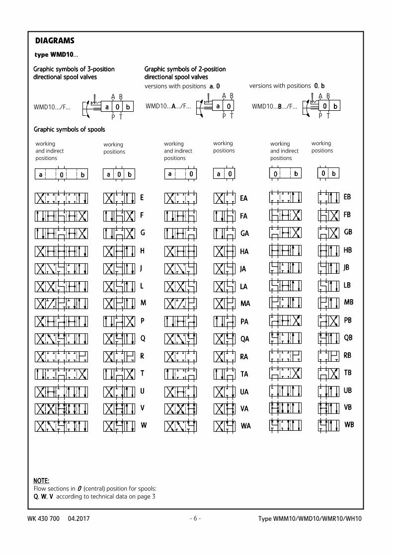
GrGrGrGrapapapaphhhhicicicic ssssymbymbymbymboooollllssss ooooffff 3333-p-p-p-poooossssititititiiiioooonnnn
directdirectdirectdirectiiiioooonnnnaaaallll spspspspoooooooollll vvvvaaaallllvvvveseseses
GrGrGrGrapapapaphhhhicicicic ssssymbymbymbymboooollllssss ooooffff spspspspoooooooollllssss
versions with positions aaaa, 0000 versions with positions 0000, b b b b
GrGrGrGrapapapaphhhhicicicic ssssymbymbymbymboooollllssss ooooffff 2222-p-p-p-poooossssititititiiiioooonnnn
directdirectdirectdirect iiiioooonnnnaaaallll spspspspoooooooollll vvvvaaaallllvvvveseseses
working
and indirect
positions
working
and indirect
positions
working
positions
working
positions
working
positions
DIAGRAMS
type WMM10...
NOTENOTENOTENOTE::::
Flow sections in 0000 (central) position for spools:
QQQQ, WWWW, VVVV according to technical data on page 3
- 4 -

Type WMM10/WMD10/WMR10/WH10 WK 430 700 04.2017- 5 -- 5 -
AAAA
CCCC
DDDD
BBBB
YYYY
A B
P T
aaaa bbbb
A B
P T
aaaa bbbb
A B
P T
aaaa bbbb
A B
P T
aaaa bbbb
aaaa bbbb aaaa bbbb aaaa bbbb aaaa bbbb
aaaa bbbb aaaa bbbb aaaa bbbb aaaa bbbb
WMM10.../...
WMM10.../FFFF...
GraGraGraGraphphphphic symic symic symic symbbbboooolslslsls oooof 2f 2f 2f 2----ppppoooositisitisitisitioooonnnn
directidirectidirectidirectioooonalnalnalnal s s s sppppoooooooollll vvvvalalalalvvvveseseses
working
and indirect
positions
GraGraGraGraphphphphic symic symic symic symbbbboooolslslsls oooof f f f spspspspoooooooolslslsls
working
positions
working
and indirect
positions
working
positions
AAAA
CCCC
DDDD
aaaa bbbb aaaa bbbb
aaaa bbbb aaaa bbbb
A B
P T
aaaa bbbbWMD10.../F...
GraphiGraphiGraphiGraphic symc symc symc symbbbbooools ls ls ls oooof f f f 2222-p-p-p-poooositisitisitisitioooonnnn
directidirectidirectidirectioooonal spnal spnal spnal spooooooool l l l vvvvalalalalvvvveseseses
working
and indirect
positions
GraphiGraphiGraphiGraphic symc symc symc symbbbbooools ls ls ls oooof spf spf spf spoooooooolslslsls
working
positions
type WMD10...
DIAGRAMS
type WMM10...
Type WMM10/WMD10/WMR10/WH10WK 430 700 04.2017 - 6 -
DIAGRAMS
aaaa 0000 bbbb aaaa 0000 0000 bbbb
EEEE
FFFF
GGGG
HHHH
JJJJ
LLLL
MMMM
PPPP
QQQQ
RRRR
TTTT
UUUU
VVVV
WWWW
EAEAEAEA
FAFAFAFA
GAGAGAGA
HAHAHAHA
JAJAJAJA
LALALALA
MAMAMAMA
PAPAPAPA
QAQAQAQA
RARARARA
TATATATA
UAUAUAUA
VAVAVAVA
WAWAWAWA
EBEBEBEB
FBFBFBFB
GBGBGBGB
HBHBHBHB
JBJBJBJB
LBLBLBLB
MBMBMBMB
PBPBPBPB
QBQBQBQB
RBRBRBRB
TBTBTBTB
UBUBUBUB
VBVBVBVB
WBWBWBWB
aaaa 0000 bbbb aaaa 0000 0000 bbbb
A B
P T
aaaa bbbb0000
A B
P T
aaaa 0000
A B
P T
0000 bbbbWMD10.../F... WMD10...BBBB.../F...WMD10...AAAA.../F...
GrGrGrGraphic aphic aphic aphic sysysysymbmbmbmbooools ls ls ls oooof f f f 2222-p-p-p-poooositisitisitisitioooonnnn
directidirectidirectidirectioooonal nal nal nal spspspspooooooool l l l vvvvalalalalvvvveseseses
working
and indirect
positions
GrGrGrGraphic aphic aphic aphic sysysysymbmbmbmbooools ls ls ls oooof f f f spspspspoooooooolslslsls
working
positions
versions with positions a a a a, 0000 versions with positions 0000, b b b b
GrGrGrGraphic aphic aphic aphic sysysysymbmbmbmbooools ls ls ls oooof f f f 3333-p-p-p-poooositisitisitisitioooonnnn
directidirectidirectidirectioooonal nal nal nal spspspspooooooool l l l vvvvalalalalvvvveseseses
working
and indirect
positions
working
and indirect
positions
working
positions
working
positions
type WMD10...
NOTENOTENOTENOTE::::
Flow sections in 0000 (central) position for spools:
QQQQ, WWWW, VVVV according to technical data on page 3
Type WMM10/WMD10/WMR10/WH10 WK 430 700 04.2017 - 7 -
aaaa 0000 bbbb
EEEE
FFFF
GGGG
HHHH
JJJJ
LLLL
MMMM
PPPP
QQQQ
RRRR
TTTT
UUUU
VVVV
WWWW
aaaa 0000 bbbb
A B
P T
aaaa bbbb0000WMR10...
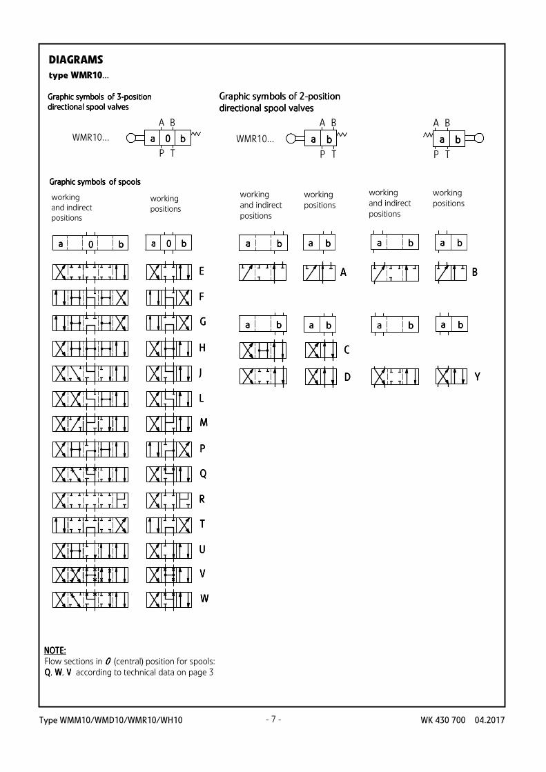
Graphic symbols Graphic symbols Graphic symbols Graphic symbols oooof f f f 3333-p-p-p-pososososititititiiiionononon
directdirectdirectdirectiiiionaonaonaonal spl spl spl spooooooool l l l vavavavallllvesvesvesves
working
and indirect
positions
Graphic symbols Graphic symbols Graphic symbols Graphic symbols oooof spf spf spf spoooooooolslslsls
working
positions
AAAA
CCCC
DDDD
aaaa bbbb aaaa bbbb
aaaa bbbb aaaa bbbb
A B
P T
aaaa bbbbWMR10...
A B
P T
aaaa bbbb
aaaa bbbb aaaa bbbb
BBBB
aaaa bbbb aaaa bbbb
YYYY
GraGraGraGraphphphphic symic symic symic symbbbboooolslslsls oooof 2f 2f 2f 2----ppppoooositisitisitisitioooonnnn
directidirectidirectidirectioooonalnalnalnal s s s sppppoooooooollll vvvvalalalalvvvveseseses
working
and indirect
positions
working
positions
working
and indirect
positions
working
positions
type WMR10...
DIAGRAMS
NOTENOTENOTENOTE::::
Flow sections in 0000 (central) position for spools:
QQQQ, WWWW, VVVV according to technical data on page 3

Type WMM10/WMD10/WMR10/WH10WK 430 700 04.2017 - 8 -
aaaa 0000 bbbb aaaa 0000 0000 bbbb
EEEE
FFFF
GGGG
HHHH
JJJJ
LLLL
MMMM
PPPP
QQQQ
RRRR
TTTT
UUUU
VVVV
WWWW
EAEAEAEA
FAFAFAFA
GAGAGAGA
HAHAHAHA
JAJAJAJA
LALALALA
MAMAMAMA
PAPAPAPA
QAQAQAQA
RARARARA
TATATATA
UAUAUAUA
VAVAVAVA
WAWAWAWA
EBEBEBEB
FBFBFBFB
GBGBGBGB
HBHBHBHB
JBJBJBJB
LBLBLBLB
MBMBMBMB
PBPBPBPB
QQQQBBBB
RBRBRBRB
TBTBTBTB
UBUBUBUB
VBVBVBVB
WBWBWBWB
aaaa 0000 bbbb aaaa 0000 0000 bbbb
WH10.../...
A B
P T
aaaa bbbb0000a b
A B
P T
aaaa 0000a
A B
P T
bbbb0000bWH10...BBBB/...WH10...AAAA/...
GrGrGrGrapapapaphhhhicicicic ssssymbymbymbymboooollllssss ooooffff 2222-p-p-p-poooossssititititiiiioooonnnn
directdirectdirectdirect iiiioooonnnnaaaallll spspspspoooooooollll vvvvaaaallllvvvveseseses
versions with positions aaaa, 0000 versions with positions 0000, b b b b
GrGrGrGrapapapaphhhhicicicic ssssymbymbymbymboooollllssss ooooffff 3333-p-p-p-poooossssititititiiiioooonnnn
directdirectdirectdirectiiiioooonnnnaaaallll spspspspoooooooollll vvvvaaaallllvvvveseseses
working
and indirect
positions
GrGrGrGrapapapaphhhhicicicic ssssymbymbymbymboooollllssss ooooffff spspspspoooooooollllssss
working
positionsworking
and indirect
positions
working
positionsworking
and indirect
positions
working
positions
type WH10...
NOTENOTENOTENOTE::::
Flow sections in 0000 (central) position for spools:
QQQQ, WWWW, VVVV according to technical data on page 3
DIAGRAMS

Type WMM10/WMD10/WMR10/WH10 WK 430 700 04.2017- 9 -
AAAA
CCCC
DDDD
BBBB
YYYY
A B
P T
aaaa bbbba
A B
P T
aaaa bbbbb
aaaa bbbb aaaa aaaa bbbb aaaa bbbb
aaaa aaaa aaaa bbbb aaaa bbbb
WH10.../...
bbbb
bbbb bbbb
A B
P T
aaaa bbbba b
WH10.../OOOO...
A B
P T
aaaa bbbba b
WH10.../OFOFOFOF...
GraphiGraphiGraphiGraphic symc symc symc symbbbbooools ls ls ls oooof f f f 2222-p-p-p-poooositisitisitisitioooonnnn
directidirectidirectidirectioooonal spnal spnal spnal spooooooool l l l vvvvalalalalvvvveseseses
working
and indirect
positions
GraphiGraphiGraphiGraphic symc symc symc symbbbbooools ls ls ls oooof spf spf spf spoooooooolslslsls
working
positions
working
and indirect
positions
working
positions
type WH10...
DIAGRAMS

Type WMM10/WMD10/WMR10/WH10WK 430 700 04.2017 - 10 -
PPPPAAAA
TTTT TTTT
BBBB
AAAA BBBB
91
167
46
69
,5
1
4
5
2
~115 ~115
type WMM10...
21° 21°
6
3
340
~
103
52 54 18,5
23
~230
76
,5
62
0,63
r 0,01/100
8
TTTT TTTT
PPPP
AAAA BBBB
AAAA BBBB
3,2*16,7
27
37,350,8
54
6,3
21
,4
32
,5
46
91 (min)
7
M6 depth 12 - 4 holes
O11,2 (max) - 4 holes*
(P, T, A, B)
69
,5(m
in)
18,5
167
30
O6,6 - 4 holes
O11 - 4 cunterbores
bbbb/0000
bbbb
aaaa
aaaa 0000
2-position versionswith spools: B, Y/EB...WB
2-position versionswith spools: A,C,D/EA...WA
3-position versionsbbbb
a/0a/0a/0a/0
OVERALL AND CONNECTION DIMENSIONS
1 - Hand lever
2 - Hand lever (optionally mounted)
3 - Sealing ring oooo-rin-rin-rin-ringggg 11112222,,,,44442222 x x x x 1111,,,,77778888 - pcs 5/set (PPPP,TTTT , TTTT , A A A A, BBBB)
4 - Overall dimension of directional spool valve:
•3-posit3-posit3-posit3-posit ioioioion springs centen springs centen springs centen springs cente rrrreeeedddd
•3333----positipositipositiposition poson poson poson pos itiitiitiitioned with doned with doned with doned with d etentetentetentetent
(spool diagrams: EEEE, FFFF, GGGG, HHHH, JJJJ, LLLL, MMMM, QQQQ, RRRR,TTTT, UUUU, VVVV, WWWW
---- acc. to page 4)
•2222----positipositipositiposition poson poson poson positiitiitiitioned with springoned with springoned with springoned with spring
•2222----positipositipositiposition poson poson poson pos itiitiitiitioned with doned with doned with doned with d etentetentetentetent
(positions aaaa, bbbb - spool diagrams: AAAA, CCCC, DDDD - acc. to page 5)
positions aaaa, 0000 - spool diagrams: EEEEAAAA, FFFFAAAA, GAGAGAGA, HHHHAAAA, JJJJA,A,A,A,
LLLLAAAA, MMMMAAAA, PPPPAAAA, QAQAQAQA, RARARARA,TTTTAAAA, UAUAUAUA, VVVVAAAA, WAWAWAWA - acc. to page 4
positions 0000, bbbb - spool diagrams: EEEEBBBB, FBFBFBFB, GBGBGBGB, HBHBHBHB, JBJBJBJB,
LB LB LB LB, MBMBMBMB, PBPBPBPB, QBQBQBQB, RBRBRBRB, TBTBTBTB, UBUBUBUB, VVVVBBBB, WBWBWBWB - acc. to page 4)
5 - Overall dimension of directional spool valve:
•2222----positipositipositiposition poson poson poson pos itiitiitiitioned with springoned with springoned with springoned with spring
•2222----positipositipositiposition poson poson poson pos itiitiitiitioned with doned with doned with doned with d etentetentetentetent
(positions aaaa, bbbb - spool diagrams: BBBB, YYYY - acc. to page 5)
6 - Positions of hand lever
7 - Porting pattern of the subplate surface compliant
with IIIISSSSOOOO 4444444400001111**** standard
designation IIIISSSSO O O O 4444444400001111-05-04-0-94 (CETOP 05)
fixing screws MMMM6666 x x x x 44440000 - - - -11110000....9999 acc. to PPPPNNNN - - - - EEEENNNN IIIISSSSOOOO 4444777766662222
pcs 4/set; tightening torque MdMdMdMd ==== 11115555 NmNmNmNm
(*) - connection with 1 hole TTTT from port side AAAA or BBBB is
sufficient - holes TTTT and TTTT are connected to the port TTTT
in the housing of directional spool valve;
8 - Subplate surface required
AAAA BBBB
AAAA BBBB

Type WMM10/WMD10/WMR10/WH10 WK 430 700 04.2017
type WMD10...
PPPPAAAA
TTTT TTTT
BBBB
AAAA BBBB
18,554
91
46
69
,5
83
21
3435,5
4,2 (stroke)4,2 (stroke)
3-position versions
2-position versionswith spools: A, C, D/EB...WB
2-position versionswith spools: EA...WA
aaaa
aaaa
bbbb
bbbb
0000
a/0a/0a/0a/0
0000
4,24,2
76 82
5 4
3
195
aaaa bbbb
0 /a 0 /a 0 /a 0 /a
90909090o 90909090 o
a b
0
a b
0
6
O6,6 - 4 holes
O11 - 4 counterbores
30
- 11 -
0,63
r 0,01/100
8
TTTT TTTT
PPPP
AAAA BBBB
AAAA BBBB
3,2*16,7
27
37,350,8
54
6,3
21
,4
32
,5
46
91 (min)
7
M6 depth 12 - 4 holes
O11,2 (max) - 4 holes*
(P, T, A, B)
69
,5(m
in)
18,5
OVERALL AND CONNECTION DIMENSIONS
1 - Rotary knob
2 - Sealing ring oooo-rin-rin-rin-ringggg 11112222,,,,44442222 x x x x 1111,,,,77778888 - pcs 5/set
(PPPP,TTTT , TTTT , A A A A, BBBB)
3 - Stroke of rotary knob for 3333-p-p-p-poooossssititititiiiioooonnnn directional spool
valve (spool diagrams: EEEE, FFFF, GGGG, HHHH, JJJJ, LLLL, MMMM, QQQQ, RRRR, TTTT, UUUU,
V V V V , WWWW - acc. to page 6)
4 - Stroke of rotary knob for 2222-p-p-p-poooossssititititiiiioooonnnn directional spool
valve (positions aaaa, 0000 - version WMD10...AAAA...;
spool diagrams: EEEEAAAA, FAFAFAFA, GGGGAAAA, HHHHAAAA, JJJJAAAA, LALALALA, MMMMAAAA, PAPAPAPA, QAQAQAQA, RRRRAAAA,
TTTTAAAA, UAUAUAUA, VVVVAAAA, WAWAWAWA - acc. to page 6
5 - Stroke of rotary knob for 2222-p-p-p-poooossssiiiittttiiiioooonnnn directional spool
valve (positions 0000, b b b b - version WMD10...BBBB...;
spool diagrams: EBEBEBEB, FBFBFBFB, GGGGBBBB, HBHBHBHB, JBJBJBJB, LBLBLBLB, MBMBMBMB, PBPBPBPB, QBQBQBQB, RBRBRBRB,
TBTBTBTB, UBUBUBUB, VBVBVBVB, WBWBWBWB - acc. to page 6; positions aaaa, bbbb; spool
diagrams: AAAA, CCCC, DDDD - acc. to page 5)
6 - Positions of rotary knob
7 - Porting pattern of the subplate surface compliant
with IIIISSSSOOOO 4444444400001111**** standard
designation IIIISSSSOOOO 4444444400001111-05-04-0-94 (CETOP 05)
fixing screws MMMM6666 x x x x 44440000 - - - -11110000....9999 acc. to PPPPNNNN - - - - EEEENNNN IIIISSSSOOOO 4444777766662222
pcs 4/set; tightening torqueeee MdMdMdMd ==== 11115555 NmNmNmNm
(****) - connection with 1 hole TTTT from port side AAAA or BBBB is
sufficient - holes TTTT and TTTT are connected to the port TTTT
in the housing of directional spool valve;
8 - Subplate surface required
AAAA BBBB
AAAA BBBB

Type WMM10/WMD10/WMR10/WH10WK 430 700 04.2017 - 12 -
type WMR10...
PPPPAAAA
TTTT TTTT
BBBB
AAAA BBBB
46
69
,5
18,554
91
3
8184,8 (max)189 (max)
O16
7,1
1
4
30v(max)
2
7
10
76
,3
bbbb aaaa0000
max backlash for 3-position versions
bbbb aaaa
max backlash for 2-position versions
3-position versions
2-position versions
4,24,2
4,2
5
6
83,3 (max)
9
2-position versions(spools B, Y)
O6,6 - 4 holes
O11 - 4 counterbores
30
OVERALL AND CONNECTION DIMENSIONS
87,5 (max)83,3 (max)
3-position versions2-position versions (spools A, C, D)
184,8 (max)
0,63
r 0,01/100
12
TTTT TTTT
PPPP
AAAA BBBB
AAAA BBBB
3,2*16,7
27
37,350,8
54
6,3
21
,4
32
,5
46
91 (min)
11
M6 depth 12 - 4 holes
O11,2 (max) - 4 holes*
(P, T, A, B)
69
,5(m
in)
18,5
1 - Pin with roller
2 - Screw fixing the position of the pin with roller
3 - Pin with roller (item 1) - optionally mounted after
screwing off the screw - item 2)
4 - Sealing ring oooo-rin-rin-rin-ringggg 11112222,,,,44442222 x x x x 1111,,,,77778888 - pcs 5/set
(PPPP, TTTT , TTTT , A A A A, BBBB)
5 - Stroke of roller for 3333-p-p-p-poooositisitisitisitioooonnnn directional spool valve
(spool diagrams: EEEE, FFFF, GGGG, HHHH, JJJJ ,LLLL, MMMM, QQQQ, RRRR, TTTT, UUUU, VVVV, WWWW
- acc. to page 7)
6 - Stroke of roller for 2222-p-p-p-poooositisitisitisitioooonnnn directional spool valve
(spool diagrams: AAAA, CCCC, DDDD, BBBB ,YYYY - acc. to page 7)
7 - Overall dimension of 3333-p-p-p-poooossssiiiittttiiiioooonnnn directional spool valve
8 - Overall dimension of 2222-p-p-p-poooossssiiiittttiiiioooonnnn directional spool valve
(spool diagrams: AAAA, CCCC, DDDD - acc. to page 7)
9 - Overall dimension of 2222-p-p-p-poooossssiiiittttiiiioooonnnn directional spool valve
(spool diagrams: BBBB, YYYY - acc. to page 7)
10 - Max angle of control cam
11 - Porting pattern of the subplate surface compliant
with IIIISSSSOOOO 4444444400001111**** standard
designation IIIISSSSOOOO 4444444400001111-05-04-0-94 (CETOP 05)
fixing screws MMMM6666 x x x x 44440000 - - - -11110000....9999 acc. to PPPPNNNN - - - - EEEENNNN IIIISSSSOOOO 4444777766662222
pcs 4/set; tightening torque MdMdMdMd ==== 11115555 NmNmNmNm
(****) - connection with 1 hole TTTT from port side A A A A or BBBB is
sufficient - holes TTTT and TTTT are connected to the port TTTT
in the housing of directional spool valve;
12- Subplate surface required
AAAA BBBB
AAAA BBBB

Type WMM10/WMD10/WMR10/WH10 WK 430 700 04.2017
aaaa bbbb
type WH10...
31 2
G1/4 depth 122 control ports (a, b)
O20 depth 1 - 2 counterbores
76
PPPPAAAA
TTTT TTTT
BBBB
AAAA BBBB
4
5
6
165
165
197
18,554
91
23
46
69
,5
O6,6 - 4 holes
30
O11 - 4 counterbores
- 13 -
0,63
r 0,01/100
8
TTTT TTTT
PPPP
AAAA BBBB
AAAA BBBB
3,2*16,7
27
37,350,8
54
6,3
21
,4
32
,5
46
91 (min)
7
M6 depth 12 - 4 holes
O11,2 (max) - 4 holes*
(P, T, A, B)
69
,5(m
in)
18,5
1 - Cap with control port aaaa
2 - Cap with control port bbbb
3 - Sealing ring oooo-rin-rin-rin-ringggg 11112222,,,,44442222 x x x x 1111,,,,77778888 - pcs 5/set
(PPPP, TTTT ,TTTT , AAAA, BBBB) 4 - Overall dimension of directional spool valve:
•3-posit3-posit3-posit3-posit ioioioion springs centen springs centen springs centen springs cente rrrreeeedddd
(spool diagrams: EEEE, FFFF, GGGG, HHHH, JJJJ, LLLL, MMMM, QQQQ, RRRR, TTTT, UUUU, VVVV, WWWW
- acc. to page 8)
•2-2-2-2-ppppoooositisitisitisitioooon witn witn witn withhhhoooout springs ut springs ut springs ut springs and and and and withwithwithwithoooout detut detut detut detentententent
(spool diagrams: AAAA, CCCC, DDDD - acc. to page 9)
•2222-p-p-p-poooositisitisitisitioooon witn witn witn withhhhoooout springs ut springs ut springs ut springs and and and and with with with with detentdetentdetentdetent
(spool schemes: AAAA, CCCC, DDDD - acc. to page 9)
5 - Overall dimension of directional spool valve:
•2222-p-p-p-poooossssiiiittttiiiioooonnnn ppppoooossssiiiittttiiiioooonenenenedddd wwwwiiiitttthhhh ssssprinprinprinpringggg (positions aaaa, 0000;
spool diagrams: EEEEAAAA, FFFFAAAA, GAGAGAGA, HHHHAAAA, JJJJAAAA, LLLLAAAA, MMMMAAAA, QAQAQAQA, RARARARA, TTTTAAAA,
UAUAUAUA, VVVVAAAA, WAWAWAWA - acc. to page 8
positions aaaa, bbbb; spool diagrams: AAAA, CCCC, DDDD - acc. to page 9)
6 - Overall dimension of directional spool valve:
•2222-p-p-p-poooossssiiiittttiiiioooonnnn ppppoooossssiiiittttiiiioooonenenenedddd wwwwiiiitttthhhh ssssprinprinprinpringggg (positions 0000, bbbb;
- spool diagrams: EEEEBBBB, FBFBFBFB, GBGBGBGB, HHHHBBBB, JBJBJBJB, LBLBLBLB, MBMBMBMB, QBQBQBQB, RBRBRBRB, TBTBTBTB,
UBUBUBUB, VVVVBBBB, WBWBWBWB - acc. to page 8
positions aaaa, bbbb; spool diagrams: BBBB, YYYY - acc. to page 9)
7 - Porting pattern of the subplate surface compliant
with IIIISSSSOOOO 4444444400001111**** standard
designation IIIISSSSOOOO 4444444400001111-05-04-0-94 (CETOP 05)
fixing screws MMMM6666 x x x x 44440000 - - - -11110000....9999 acc. to PPPPNNNN - - - - EEEENNNN IIIISSSSOOOO 4444777766662222
pcs 4/set; tightening torque MdMdMdMd ==== 11115555 NmNmNmNm
(****) - connection with 1 hole TTTT from port side AAAA or BBBB is
sufficient - holes TTTT and TTTT are connected to the port TTTT
in the housing of directional spool valve
8 - Subplate surface required
AAAA BBBB
AAAA BBBB
OVERALL AND CONNECTION DIMENSIONS

Type WMM10/WMD10/WMR10/WH10WK 430 700 04.2017
PPPP →→→→ AAAA PPPP →→→→ B B B B AAAA →→→→TTTT BBBB →→→→TTTT
BBBB
CCCC
YYYY
EEEE
FFFF
GGGG
HHHH
JJJJ
LLLL
MMMM
PPPP
QQQQ
RRRR
TTTT
U, VU, VU, VU, V
WWWW
14141414
3333 9999
3333 2222 2222
---- ----
----
4444 4444 1111 1111
2222
AAAA
DDDD 5555
6666
2222 11111111
14141414
6666
17171717 17171717
9999
20202020 20202020
11111111
3333
3333
5555
---- ----
1414141414141414 9999 9999
10101010 10101010 7777
1414141412121212 77776666
7777
141414141414141433333333
15151515 15151515
14141414
14141414 14141414
666614141414 12121212 7777
15151515 15151515 1111 6666
17171717 20202020 9999
11111111 1111111115151515 15151515
15151515 15151515 191919191111
14141414
8888 8888
8888
8888 8888
9999 9999
10101010
10101010
10101010
10101010
11111111
11111111
12121212
12121212
12121212
12121212
12121212
12121212
12121212
12121212
12121212
12121212
12121212 12121212
13131313 13131313
13131313 13131313
13131313 13131313
13131313 13131313
14141414 14141414
14141414
15151515
16161616 16161616
16161616
spool symbolspool symbolspool symbolspool symbol
flow direction
characterischaracterischaracterischaracteris tic ctic ctic ctic cururururve ve ve ve nnnnumberumberumberumber
diagrams acc.
to pages 8, 9
0000 11110000 22220000 33330000 44440000 55550000 66660000 77770000 88880000 99990000 111100000000 111166660000111111110000
0000,,,,5555
2222,,,,0000
1111,,,,0000
1111,,,,5555
∆∆ ∆∆ p
p
p
p
[M
Pa
[MP
a[M
Pa
[MP
a]] ]]
QQQQ [dm[dm[dm[dm /min /min /min /min]]]]3333
2222,,,,5555
3333,,,,0000
3333,,,,5555
0000,,,,5555
2222,,,,0000
1111,,,,0000
1111,,,,5555
2222,,,,5555
3333,,,,0000
3333,,,,5555
111122220000 111133330000 111144440000 111155550000
∆∆ ∆∆ p
p
p
p
[M
Pa
[MP
a[M
Pa
[MP
a]] ]]
0000 11110000 22220000 33330000 44440000 55550000 66660000 77770000 88880000 99990000 111100000000 111166660000111111110000
QQQQ [dm[dm[dm[dm /min /min /min /min]]]]3333
111122220000 111133330000 111144440000 111155550000
0000 11110000 22220000 33330000 44440000 55550000 66660000 77770000 88880000 99990000 111100000000 111166660000111111110000
QQQQ [dm[dm[dm[dm /min /min /min /min]]]]3333
111122220000 111133330000 111144440000 111155550000
0000,,,,5555
2222,,,,0000
1111,,,,0000
1111,,,,5555
2222,,,,5555
3333,,,,0000
3333,,,,5555
∆∆ ∆∆ p
p
p
p
[M
Pa
[MP
a[M
Pa
[MP
a]] ]]
8
9
10
11
13
18
12
1
2
3
4
5
6
7
15
16
14
- 14 -
•••• type WMM10.../...; WMM10.../F...
•••• type WMD10.../F...
• type WMR10...
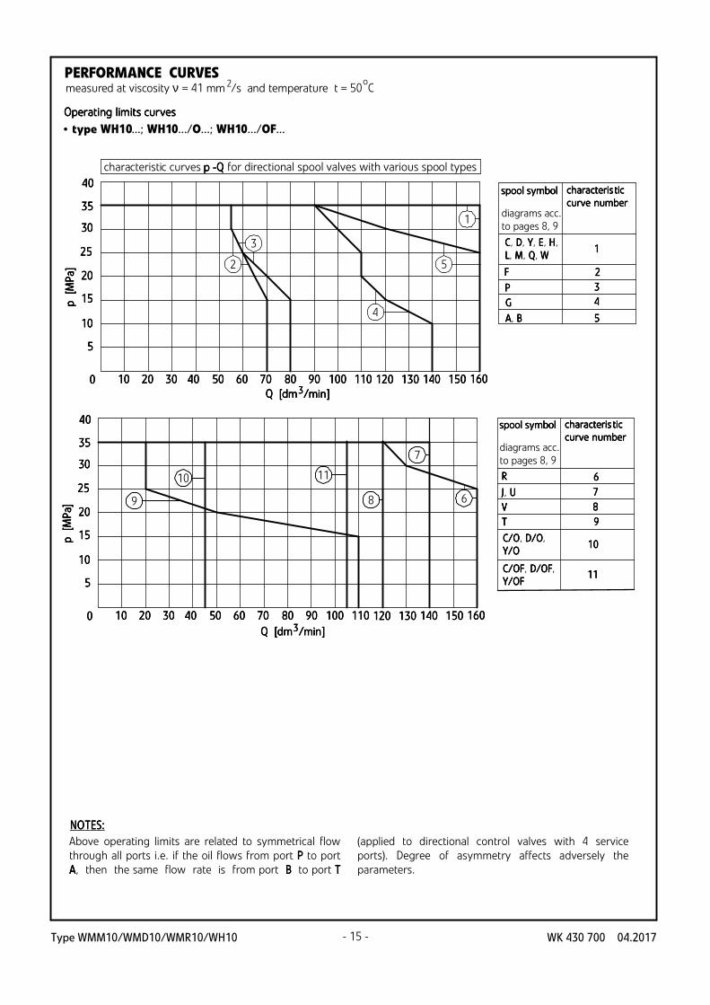
• type WH10...; WH10.../O...; WH10.../OF...
PERFORMANCE CURVES measured at viscosity ν = 41 mm /s and temperature t = 50 C2 o
FlFlFlFloooow resw resw resw resiiiiststststaaaance cnce cnce cnce cururururvesvesvesves
characteristic curves ∆pppp (QQQQ) for directional spool valves with
various spool types
Type WMM10/WMD10/WMR10/WH10 WK 430 700 04.2017 - 15 -
• type WH10...; WH10.../O...; WH10.../OF...
5555
11110000
11115555
22220000
22225555
33330000
0000 11110000 22220000 33330000 44440000 55550000 66660000 77770000 88880000 99990000 111100000000 111111110000
p
p
p
p
[MP
a[M
Pa
[MP
a[M
Pa]] ]]
Q Q Q Q [dm[dm[dm[dm /min /min /min /min]]]]3333
33335555
44440000
111122220000 111133330000 111144440000 111155550000 111166660000
1
2
3
4
5
5555
11110000
11115555
22220000
22225555
33330000
0000 11110000 22220000 33330000 44440000 55550000 66660000 77770000 88880000 99990000 111100000000 111111110000
p
p
p
p
[MP
a[M
Pa
[MP
a[M
Pa]] ]]
Q Q Q Q [dm[dm[dm[dm /min /min /min /min]]]]3333
33335555
44440000
111122220000 111133330000 111144440000 111155550000 111166660000
8
1110
6
7
9
CCCC, DDDD, Y Y Y Y, E E E E, H H H H,
LLLL, M M M M, Q Q Q Q, W W W W
PPPP
FFFF
GGGG
AAAA, B B B B
1111
2222
3333
4444
5555
spool symbolspool symbolspool symbolspool symbol characterischaracterischaracterischaracteris tictictictic
curcurcurcurve ve ve ve nnnnumberumberumberumberdiagrams acc.
to pages 8, 9
RRRR
C/C/C/C/OOOO, DDDD////OOOO,
Y/Y/Y/Y/OOOO
VVVV
C/C/C/C/OFOFOFOF, DDDD////OFOFOFOF,
Y/Y/Y/Y/OFOFOFOF
6666
7 7 7 7
8 8 8 8
9 9 9 9
10101010
11111111
JJJJ, U U U U
TTTT
spool symbolspool symbolspool symbolspool symbol characterischaracterischaracterischaracteris tictictictic
curcurcurcurve ve ve ve nnnnumberumberumberumberdiagrams acc.
to pages 8, 9
PERFORMANCE CURVES measured at viscosity ν = 41 mm /s and temperature t = 50 C2 o
OperOperOperOperatatatatiiiing ng ng ng llllimimimimitititits curs curs curs curvesvesvesves
Above operating limits are related to symmetrical flow
through all ports i.e. if the oil flows from port PPPP to port
AAAA, then the same flow rate is from port BBBB to port TTTT
(applied to directional control valves with 4 service
ports). Degree of asymmetry affects adversely the
parameters.
NNNNOOOOTTTTEEEES:S:S:S:
characteristic curves p -Q p -Q p -Q p -Q for directional spool valves with various spool types
Type WMM10/WMD10/WMR10/WH10WK 430 700 04.2017 - 16 -
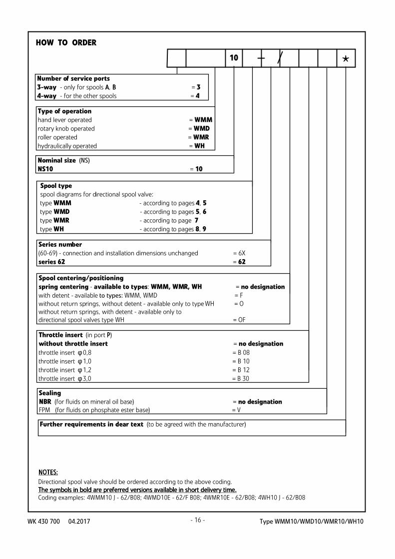
*10
Spool type
spool diagrams for directional spool valve:
type WMM - according to pages 4, 5
type WMD - according to pages 5, 6
type WMR - according to page 7
type WH - according to pages 8, 9
Spool centering/positioning
spring centering - available to types: WMM, WMR, WH = no designation
with detent - available to types: WMM, WMD = F
without return springs, without detent - available only to type WH = O
without return springs, with detent - available only to
directional spool valves type WH = OF
Type of operation
hand lever operated = WMM
rotary knob operated = WMD
roller operated = WMR
hydraulically operated = WH
Number of service ports
3-way - only for spools AAAA, BBBB = 3
4-way - for the other spools = 4
Series number
(60-69) - connection and installation dimensions unchanged = 6X
series 62 = 62
Sealing
NBR (for fluids on mineral oil base) = no designation
FPM (for fluids on phosphate ester base) = V
Further requirements in clear text (to be agreed with the manufacturer)
Nominal size (NS)
NS10 = 10
Throttle insert (in port PPPP)
without throttle insert = no designation
throttle insert φ 0,8 = B 08
throttle insert φ 1,0 = B 10
throttle insert φ 1,2 = B 12
throttle insert φ 3,0 = B 30
HOW TO ORDER
Directional spool valve should be ordered according to the above coding.
The symbols in bold are preferred versions The symbols in bold are preferred versions The symbols in bold are preferred versions The symbols in bold are preferred versions available available available available in short delivery time.in short delivery time.in short delivery time.in short delivery time.
Coding examples: 4WMM10 J - 62/B08; 4WMD10E - 62/F B08; 4WMR10E - 62/B08; 4WH10 J - 62/B08
NNNNOOOOTTTTEEEES:S:S:S:

Type WMM10/WMD10/WMR10/WH10 WK 430 700 04.2017- 17 -
M
PPPP
BBBBAAAA
TTTT 4WH10 4WH10 4WH10 4WH10 JJJJ - 62 - 62 - 62 - 62
3URED4 3URED4
AAAA BBBB
M
PPPP TTTT 4WMM10 J 4WMM10 J 4WMM10 J 4WMM10 J - 62 - 62 - 62 - 62
type WMM10
type WH10
EXAMPLES OF APPLICATION
IN HYDRAULIC SYSTEM
SUBPLATES AND FIXING SCREWS
Subplates must be ordered according to data sheet
WWWWK K K K 444499996 6 6 6 555522220000. Subplate symbols:
G 66/01 - threaded connections G 3/8
G 67/01 - threaded connections G 1/2
G 89/01 - threaded connections G 1/4
G 67/02 - threaded connections M22 x 1,5
G 534/01 - threaded connections G 3/4
Subplates and fixing screws MMMM6 6 6 6 x x x x 44440 0 0 0 - - - - 11110,0,0,0,9999 - pcs 4/set
according to PPPPNNNN - - - - EEEENNNN IIIISSSSOOOO 4444777766662222 must be ordered
separately.
Tightening torque MMMMd = d = d = d = 11115 Nm5 Nm5 Nm5 Nm
NNNNOOOOTTTTE:E:E:E:
SSSSubpubpubpubpllllate ate ate ate symbosymbosymbosymbol l l l iiiin bn bn bn boooold ld ld ld iiiis ts ts ts the preferredhe preferredhe preferredhe preferred
versversversversiiiioooon n n n aaaavvvvaaaaiiiillllabababable le le le iiiin n n n sssshhhhort deort deort deort delllliiiivery tvery tvery tvery t ime.ime.ime.ime.

Type WMM10/WMD10/WMR10/WH10WK 430 700 04.2017
PONAR Wadowice S.A.
ul. Wojska Polskiego 29
34-100 Wadowice
tel. +48 33 488 21 00 fax.+48 33 488 21 03
www.ponar-wadowice.pl
- 18 -
Recommended