Instructor: Eng. Nada Khatib
Website: http://www.philadelphia.edu.jo/academics/nkhatib/
Digital Communication (650533) CH 3
Pulse Modulation
Philadelphia University/Faculty of Engineering
Communication and Electronics Engineering
Eng. Nada Khatib Ch 3- lecture 2/5 1
Outline • Introduction
• PCM – Sampling Process
– Quantization Process
– Encoding • Line codes
– Regeneration
– Noise in PCM
• TDM
• DPCM
• Delta Modulation
Eng. Nada Khatib Ch 3- PCM 2
Introduction • Analog signal versus digital signal
• Almost every communication system in use today is a digital.
– Cell phone system (GSM, UMTS,LTE)
– GPS, etc
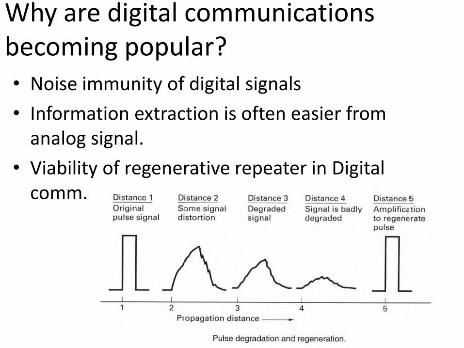
Why are digital communications becoming popular? • Noise immunity of digital signals
• Information extraction is often easier from analog signal.
• Viability of regenerative repeater in Digital comm.
Why digital communication? • The ability to detect and correct errors by
using error detection and correction techniques.
• The ability to compress data
• The ability to securely send data by using encryption for example.
Disadvantage digital communication
– More bandwidth.
– Synchronization is more complicated.
PCM
• PCM = Pulse code Modulation
• It is a method of converting an analog signal into a digital binary signal (A/D conversion).
• An analog signal can be converted into binary digital signal by means of
– Sampling
– Quantization
– Encoding
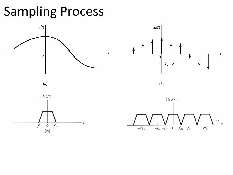
Sampling Process
Sampling Process
• Ts= sampling interval
• fs ≥ 2fm Nyquist criterion
• Fs=2fm Nyquist rate
• Fs> 2fm oversampling
• Fs<2fm undersampling → aliasing
• Aliasing = spectral folding = tail inversion
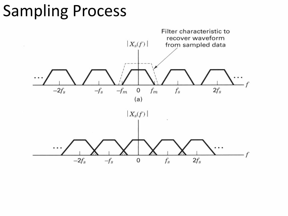
Sampling Process
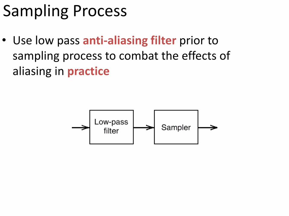
Sampling Process
• Use low pass anti-aliasing filter prior to sampling process to combat the effects of aliasing in practice

Sampling Process
• the standard CCITT voice channel, 300–3400 Hz (a bandwidth of 3100 Hz)
• So for telephony the sampling rate is 8000 samples per second, or 8 kHz.
• And the sampling period is therefore 1/8 kHz (i.e., 125 μs).
Quantization
• The process of transformation the sample amplitudes of a signal into discrete amplitude taken from a finite set of possible amplitude (Lo, L1, L2,..).
• Number of representation levels is L
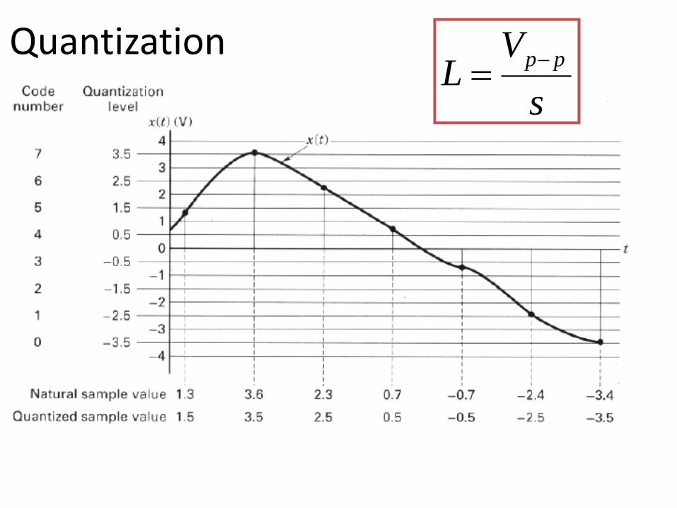
Quantization
s
VL
pp
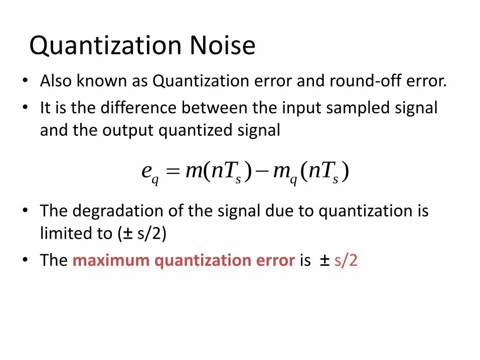
Quantization Noise • Also known as Quantization error and round-off error.
• It is the difference between the input sampled signal and the output quantized signal
• The degradation of the signal due to quantization is limited to (± s/2)
• The maximum quantization error is ± s/2
)()( sqsq nTmnTme
Quantization Noise
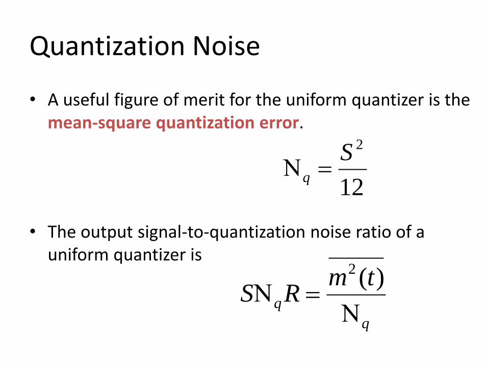
• A useful figure of merit for the uniform quantizer is the mean-square quantization error.
• The output signal-to-quantization noise ratio of a uniform quantizer is
12
2Sq
q
q
tmRS
)(2
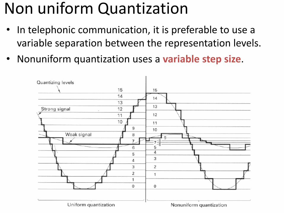
Non uniform Quantization • In telephonic communication, it is preferable to use a
variable separation between the representation levels.
• Nonuniform quantization uses a variable step size.
Non uniform Quantization
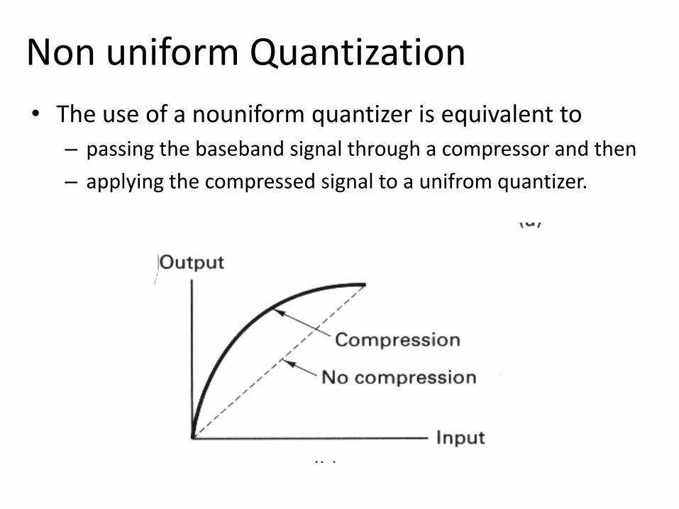
• The use of a nouniform quantizer is equivalent to
– passing the baseband signal through a compressor and then
– applying the compressed signal to a unifrom quantizer.
Non uniform Quantization
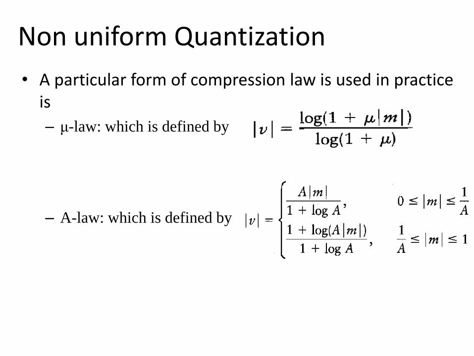
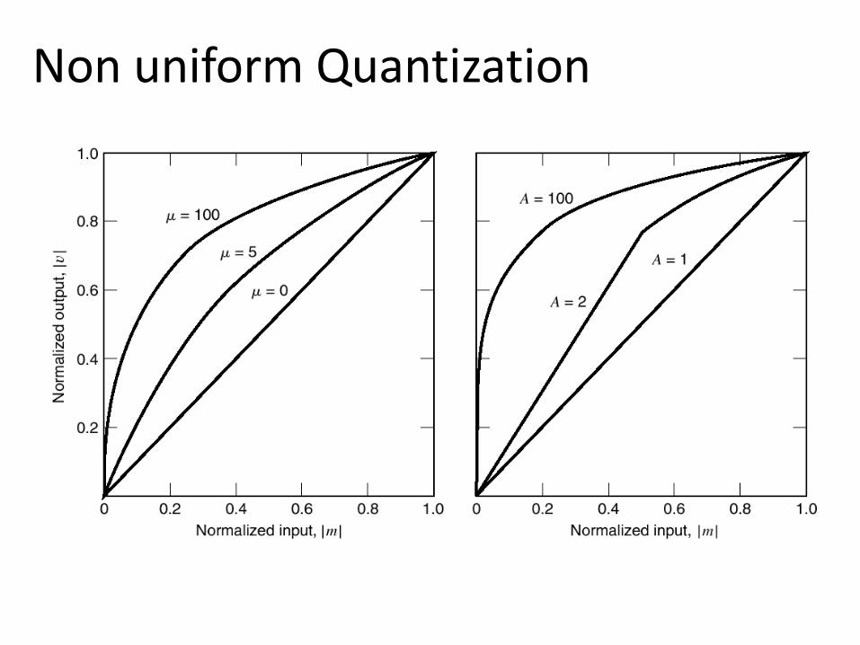
• A particular form of compression law is used in practice is
– μ-law: which is defined by
– A-law: which is defined by
Non uniform Quantization
Non uniform Quantization
• The compressed samples must be restored to their
original values at receiver by using an expander with a
characteristic complements to that of the compressor.
• The combination of a compressor and an expander is
called a compander.
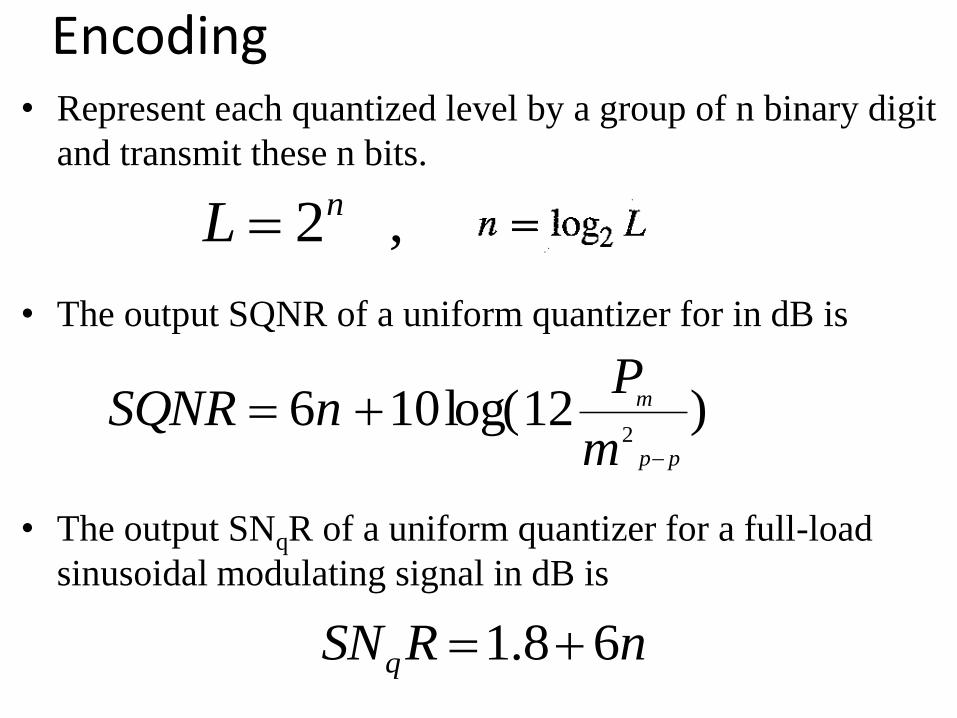
Encoding • Represent each quantized level by a group of n binary digit
and transmit these n bits.
• The output SQNR of a uniform quantizer for in dB is
• The output SNqR of a uniform quantizer for a full-load
sinusoidal modulating signal in dB is
,2nL
nRSNq 68.1
)12log(1062
pp
m
m
PnSQNR
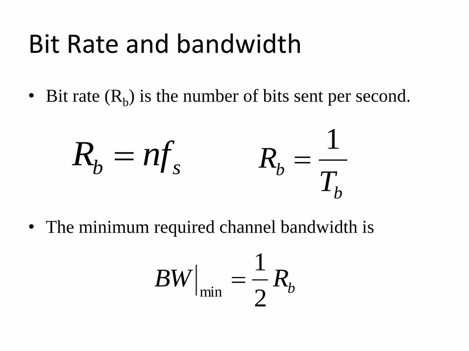
Bit Rate and bandwidth
• Bit rate (Rb) is the number of bits sent per second.
• The minimum required channel bandwidth is
sb nfR
bRBW2
1min
b
bT
R1
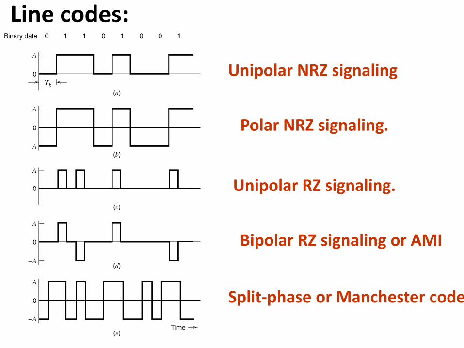
Split-phase or Manchester code.
Unipolar NRZ signaling
Polar NRZ signaling.
Unipolar RZ signaling.
Bipolar RZ signaling or AMI
Line codes:
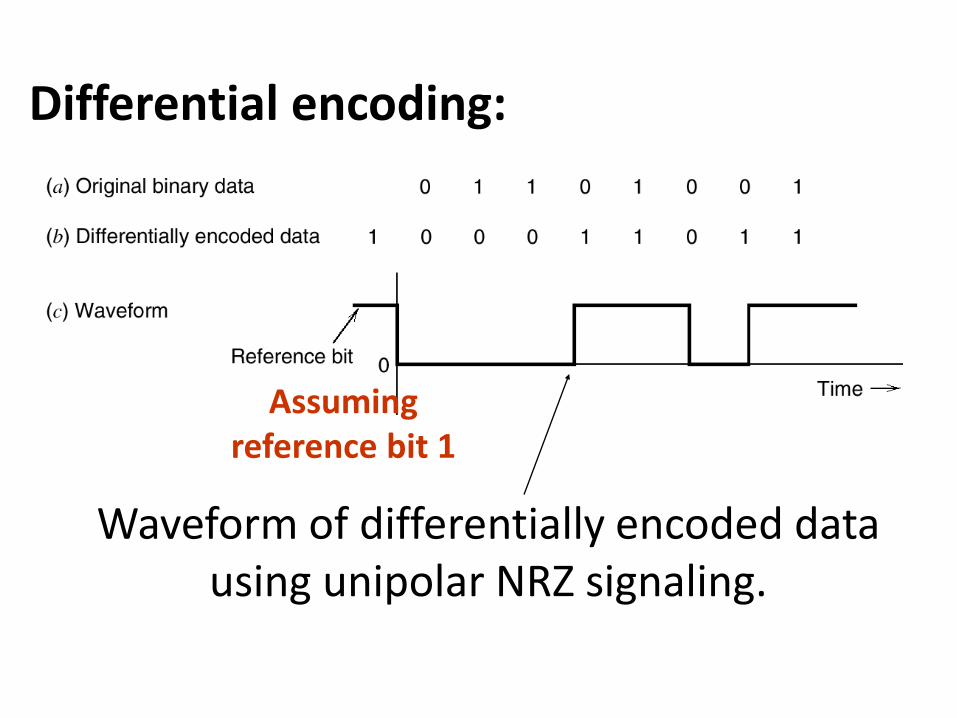
Waveform of differentially encoded data using unipolar NRZ signaling.
Assuming reference bit 1
Differential encoding:
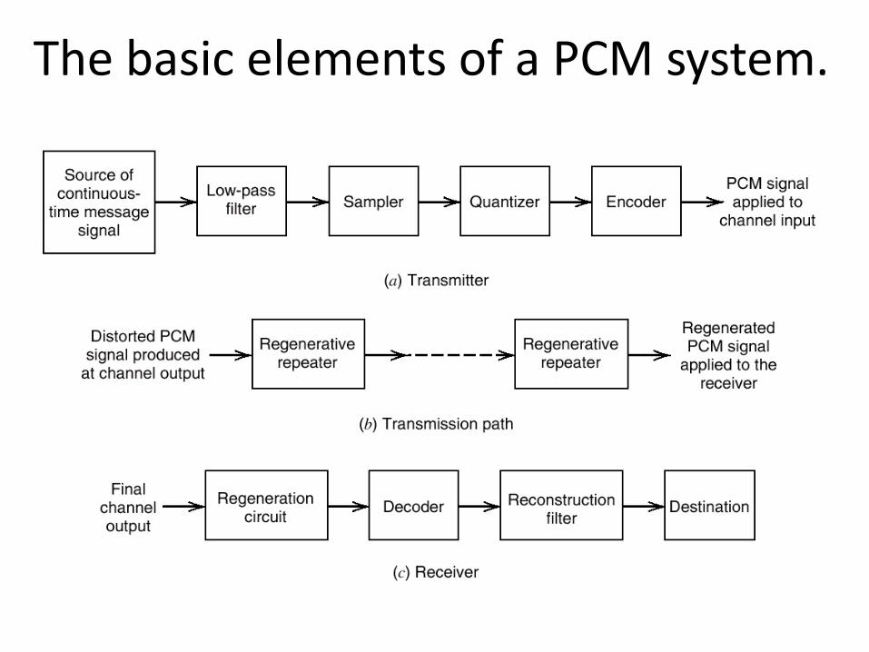
The basic elements of a PCM system.
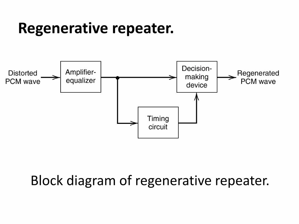
Regenerative repeater.
Block diagram of regenerative repeater.
Noise in PCM system • Quantization Noise:
– Signal dependent
– Under the designer’s control
• Channel Noise:
– The main effect of channel noise is o introduce bit error into
the received signal.
– Bit error rate (BER) = PeRb
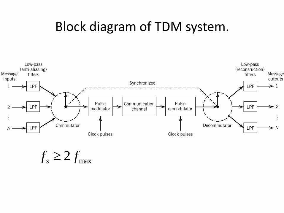
Block diagram of TDM system.
max2 ffs
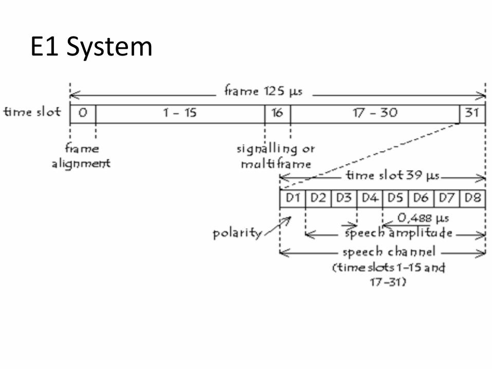
E1 System
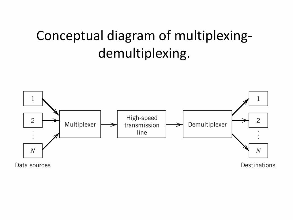
Conceptual diagram of multiplexing-demultiplexing.
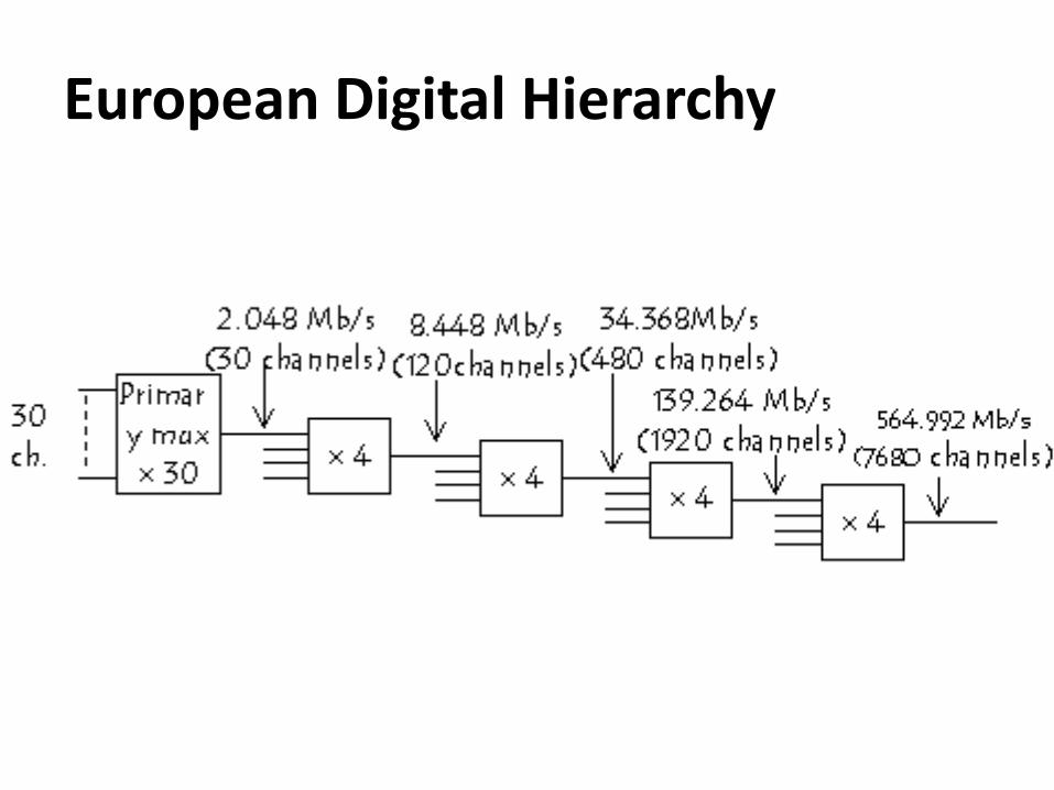
European Digital Hierarchy
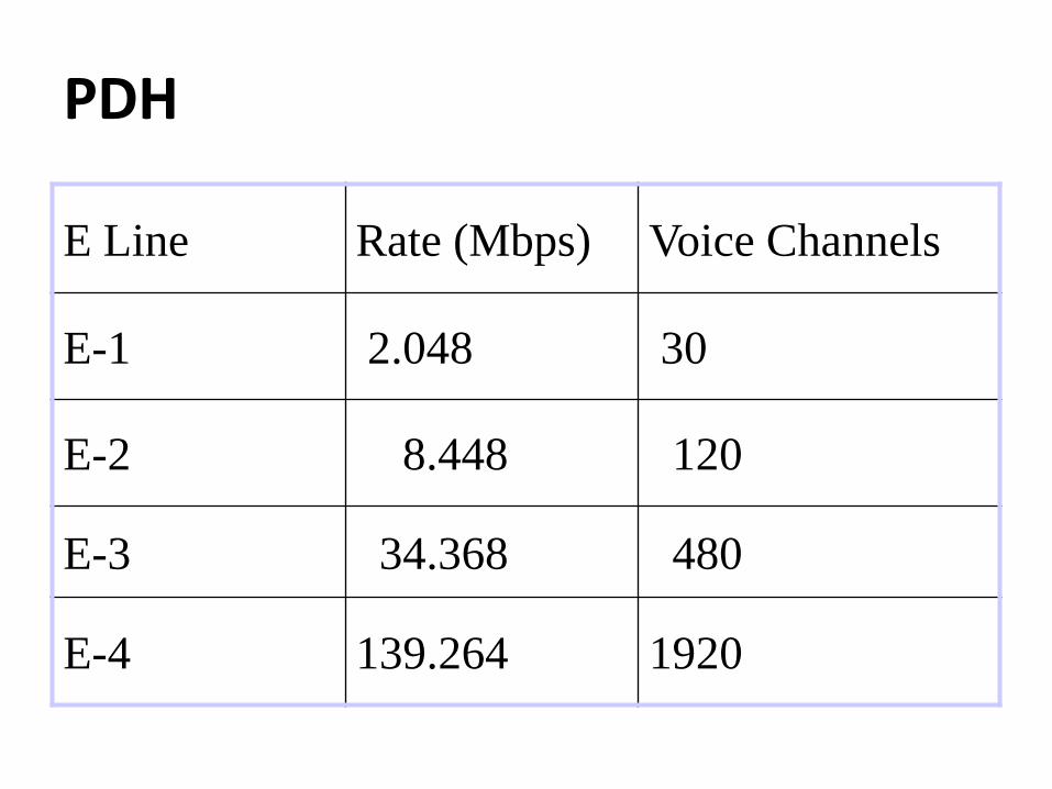
PDH
Voice Channels Rate (Mbps) E Line
30 2.048 E-1
120 8.448 E-2
480 34.368 E-3
1920 139.264 E-4
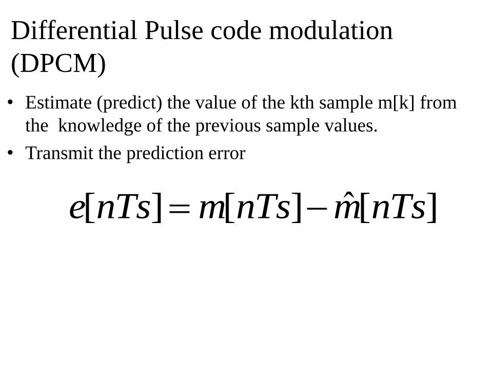
Differential Pulse code modulation
(DPCM)
• Estimate (predict) the value of the kth sample m[k] from
the knowledge of the previous sample values.
• Transmit the prediction error
][ˆ][][ nTsmnTsmnTse
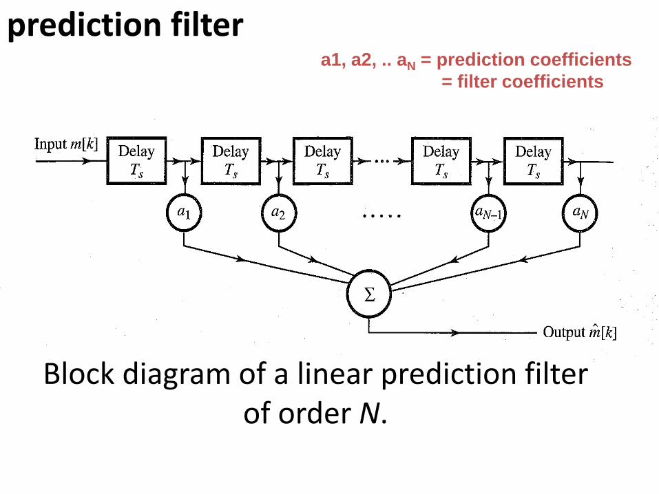
Block diagram of a linear prediction filter of order N.
prediction filter a1, a2, .. aN = prediction coefficients
= filter coefficients
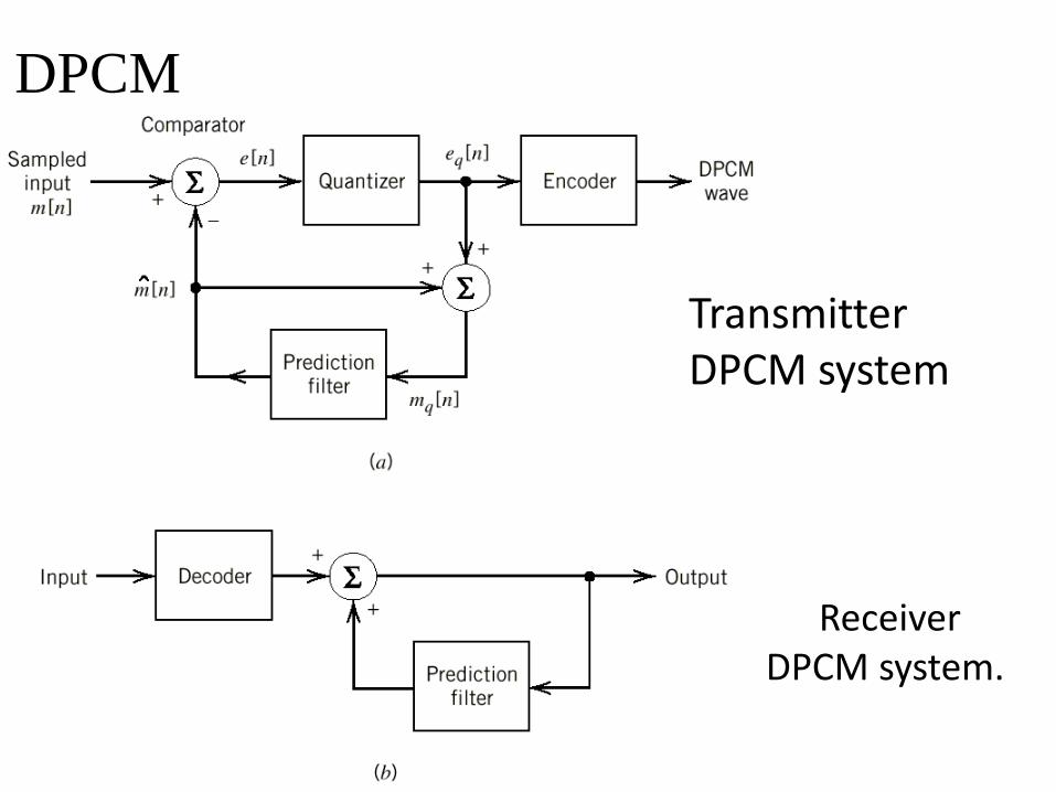
Receiver DPCM system.
DPCM
Transmitter DPCM system
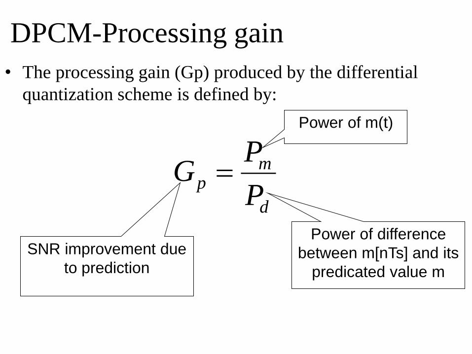
DPCM-Processing gain
• The processing gain (Gp) produced by the differential
quantization scheme is defined by:
d
mp
P
PG
Power of m(t)
Power of difference
between m[nTs] and its
predicated value m
SNR improvement due
to prediction
Delta Modulation (DM)
• The incoming signal is oversampled to increase the
correlation between adjacent samples of the signal.
• Quantized into only two levels (encoded by 1-bit).
• DM provides a staircase approximation to the
oversampled version of the message signal.
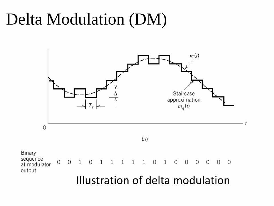
Illustration of delta modulation
Delta Modulation (DM)
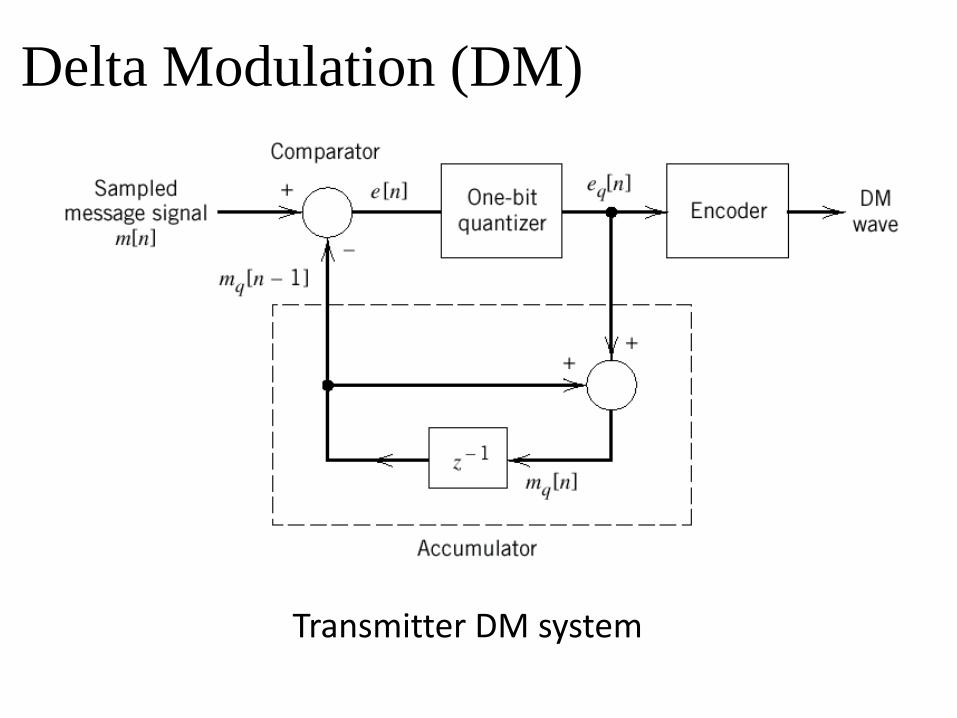
Transmitter DM system
Delta Modulation (DM)
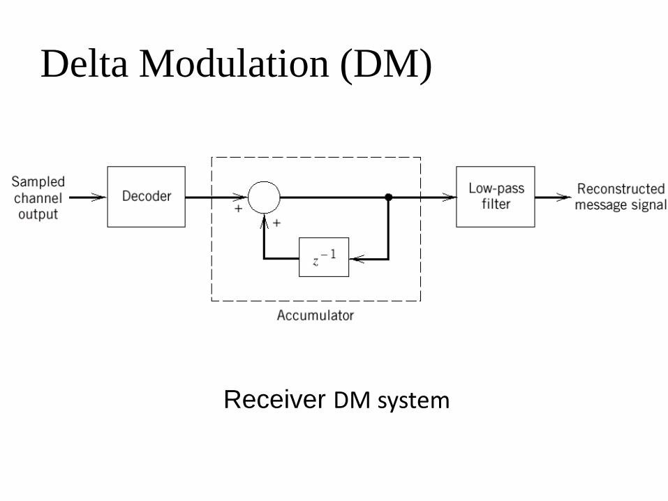
Receiver DM system
Delta Modulation (DM)
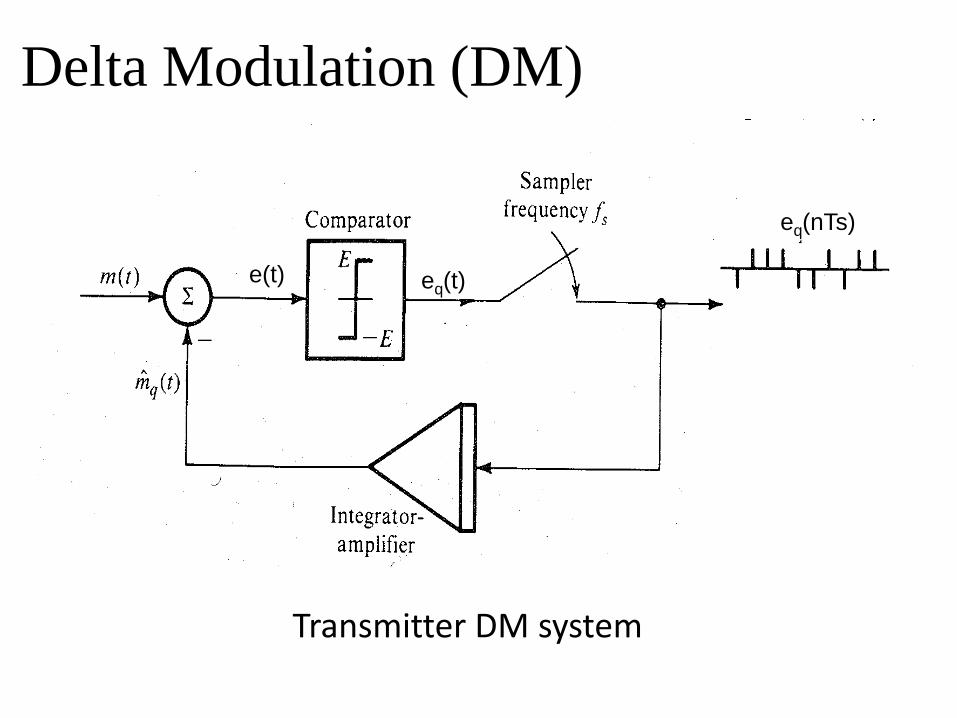
Transmitter DM system
Delta Modulation (DM)
e(t) eq(t)
eq(nTs)
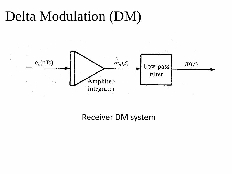
Receiver DM system
Delta Modulation (DM)
eq(nTs)
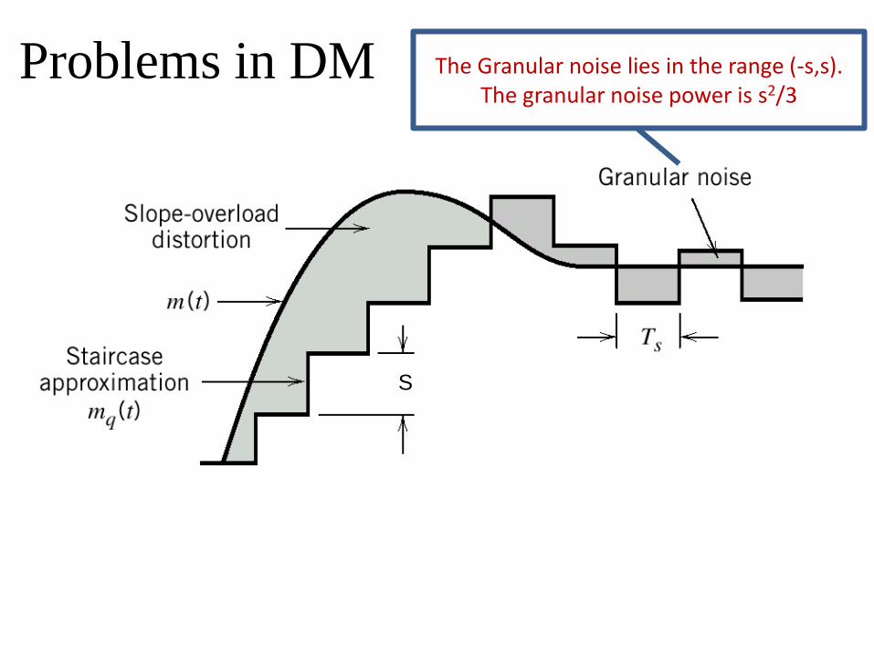
Problems in DM The Granular noise lies in the range (-s,s). The granular noise power is s2/3
S
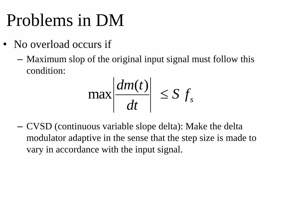
Problems in DM
• No overload occurs if
– Maximum slop of the original input signal must follow this
condition:
– CVSD (continuous variable slope delta): Make the delta
modulator adaptive in the sense that the step size is made to
vary in accordance with the input signal.
sfSdt
tdm
)(max
Recommended