DHT PROJECT
OF
HINDUSTAN PETROLEUM CORPORATION LIMITED
AT
MUMBAI
SECTION. 3.0
TECHNICAL DOCUMENTATION

HPCL Mumbai TENDER FOR ABOVE GROUND AND UNDERGROUND PIPING WORKS Section 1.8DHT Project44LK - 5100 Rev. C
Sr. No.
Item Description Size 1(inch)/ (mm))
Size 2(inch)/ (mm)
Type End Special Requirement
Rating Schedule / Thickness
Specification Unit Quantity
1 Supply of ReinforcementSupplying Fusion bonded Epoxy coated High yield strength deformed bars TMT Fe500 conforming to IS: 1786 of Tisco/S.A.I.L. /R.I.N.L. (V.S.P.)/ IISCO make. Fusion bonded epoxy coated as per IS 13620 & PSL limited manufacturer’s specification.
Metric Ton 110
2 Supply of ReinforcementSupplying Fusion bonded Epoxy coated Round Plain steel bars conforming to IS 2062 / IS 432 Part 1 (Indicative Quantity)
Metric Ton 1
3 Supply of Structural SteelSupplying steel conforming to IS:2062 : 2006 ( Grade A / Grade B ) of SAIL / R.I.N.L / TATA / IISCO or approved equivalent as approved by Owner / Consultant.
Metric Ton 19
4 Supply of Carbon Steel Pipes, ASTM A 106 GR.B,SMLS,ASME B-36.10
1 PE XS A5Y Meters 10
5 Supply of Carbon Steel Pipes, ASTM A 106 GR.B,SMLS,ASME B-36.10
1.5 PE XS A5Y Meters 5
6 Supply of Carbon Steel Pipes, ASTM A 106 GR.B,SMLS,ASME B-36.10
1.5 PE XS B5Y Meters 5
7 Supply of Carbon Steel Pipes, ASTM A 106 GR.B,SMLS,ASME B-36.10
2 BE XS A5Y Meters 15
8 Supply of Carbon Steel Pipes, ASTM A 106 GR.B,SMLS,ASME B-36.10
2 BE STD A1A Meters 30
9 Supply of Carbon Steel Pipes, IS 1239-I (BLACK), DIM STD AS PER IS 1239-I, C WELDED
4 BE Cement Lined HVY A5Y Meters 10
10 Supply of Carbon Steel Pipes, IS 1239-I (BLACK), DIM STD AS PER IS 1239-I, C WELDED
6 BE Cement Lined HVY A5Y Meters 40
11 Supply of Carbon Steel Pipes, IS-3589 GR.330, DIM STD AS PER IS-3589,WELDED
8 BE Cement Lined 6 A5Y Meters 90
Document No. 44LK-5100-718/K.02/0027 SCHEDULE OF ITEMS FOR SUPPLY
Page 1 of 11
HPCL Mumbai TENDER FOR ABOVE GROUND AND UNDERGROUND PIPING WORKS Section 1.8DHT Project44LK - 5100 Rev. C
Sr. No.
Item Description Size 1(inch)/ (mm))
Size 2(inch)/ (mm)
Type End Special Requirement
Rating Schedule / Thickness
Specification Unit Quantity
Document No. 44LK-5100-718/K.02/0027 SCHEDULE OF ITEMS FOR SUPPLY
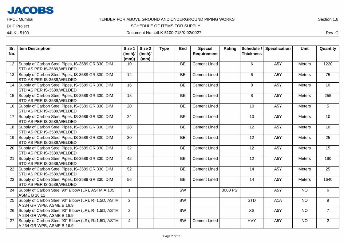
12 Supply of Carbon Steel Pipes, IS-3589 GR.330, DIM STD AS PER IS-3589,WELDED
10 BE Cement Lined 6 A5Y Meters 1220
13 Supply of Carbon Steel Pipes, IS-3589 GR.330, DIM STD AS PER IS-3589,WELDED
12 BE Cement Lined 6 A5Y Meters 75
14 Supply of Carbon Steel Pipes, IS-3589 GR.330, DIM STD AS PER IS-3589,WELDED
16 BE Cement Lined 8 A5Y Meters 10
15 Supply of Carbon Steel Pipes, IS-3589 GR.330, DIM STD AS PER IS-3589,WELDED
18 BE Cement Lined 8 A5Y Meters 255
16 Supply of Carbon Steel Pipes, IS-3589 GR.330, DIM STD AS PER IS-3589,WELDED
20 BE Cement Lined 10 A5Y Meters 5
17 Supply of Carbon Steel Pipes, IS-3589 GR.330, DIM STD AS PER IS-3589,WELDED
24 BE Cement Lined 10 A5Y Meters 10
18 Supply of Carbon Steel Pipes, IS-3589 GR.330, DIM STD AS PER IS-3589,WELDED
28 BE Cement Lined 12 A5Y Meters 10
19 Supply of Carbon Steel Pipes, IS-3589 GR.330, DIM STD AS PER IS-3589,WELDED
30 BE Cement Lined 12 A5Y Meters 25
20 Supply of Carbon Steel Pipes, IS-3589 GR.330, DIM STD AS PER IS-3589,WELDED
32 BE Cement Lined 12 A5Y Meters 15
21 Supply of Carbon Steel Pipes, IS-3589 GR.330, DIM STD AS PER IS-3589,WELDED
42 BE Cement Lined 12 A5Y Meters 190
22 Supply of Carbon Steel Pipes, IS-3589 GR.330, DIM STD AS PER IS-3589,WELDED
52 BE Cement Lined 14 A5Y Meters 25
23 Supply of Carbon Steel Pipes, IS-3589 GR.330, DIM STD AS PER IS-3589,WELDED
56 BE Cement Lined 14 A5Y Meters 1640
24 Supply of Carbon Steel 90° Elbow (LR), ASTM A 105, ASME B 16.11
1 SW 3000 PSI A5Y NO 6
25 Supply of Carbon Steel 90° Elbow (LR), R=1.5D, ASTM A 234 GR WPB, ASME B 16.9
2 BW STD A1A NO 9
26 Supply of Carbon Steel 90° Elbow (LR), R=1.5D, ASTM A 234 GR WPB, ASME B 16.9
2 BW XS A5Y NO 7
27 Supply of Carbon Steel 90° Elbow (LR), R=1.5D, ASTM A 234 GR WPB, ASME B 16.9
4 BW Cement Lined HVY A5Y NO 2
Page 2 of 11

HPCL Mumbai TENDER FOR ABOVE GROUND AND UNDERGROUND PIPING WORKS Section 1.8DHT Project44LK - 5100 Rev. C
Sr. No.
Item Description Size 1(inch)/ (mm))
Size 2(inch)/ (mm)
Type End Special Requirement
Rating Schedule / Thickness
Specification Unit Quantity
Document No. 44LK-5100-718/K.02/0027 SCHEDULE OF ITEMS FOR SUPPLY
28 Supply of Carbon Steel 90° Elbow (LR), R=1.5D, ASTM A 234 GR WPB, ASME B 16.9
6 BW Cement Lined HVY A5Y NO 16
29 Supply of Carbon Steel 90° Elbow (LR), R=1.5D, ASTM A 234 GR WPB-W, ASME B 16.9
8 BW Cement Lined 6 A5Y NO 18
30 Supply of Carbon Steel 90° Elbow (LR), R=1.5D, ASTM A 234 GR WPB-W, ASME B 16.9
10 BW Cement Lined 6 A5Y NO 30
31 Supply of Carbon Steel 90° Elbow (LR), R=1.5D, ASTM A 234 GR WPB-W, ASME B 16.9
12 BW Cement Lined 6 A5Y NO 10
32 Supply of Carbon Steel 90° Elbow (LR), R=1.5D, ASTM A 234 GR WPB-W, ASME B 16.9
16 BW Cement Lined 8 A5Y NO 6
33 Supply of Carbon Steel 90° Elbow (LR), R=1.5D, ASTM A 234 GR WPB-W, ASME B 16.9
18 BW Cement Lined 8 A5Y NO 9
34 Supply of Carbon Steel 90° Elbow (LR), R=1.5D, ASTM A 234 GR WPB-W, ASME B 16.9
24 BW Cement Lined 10 A5Y NO 3
35 Supply of Carbon Steel 90° Elbow (LR), R=1.5D, ASTM A 234 GR WPB-W, ASME B 16.9
28 BW Cement Lined 12 A5Y NO 2
36 Supply of Carbon Steel 90° Elbow (LR), R=1.5D, ASTM A 234 GR WPB-W, ASME B 16.9
30 BW Cement Lined 12 A5Y NO 3
37 Supply of Carbon Steel 90° Elbow (LR), R=1.5D, ASTM A 234 GR WPB-W, ASME B 16.9
32 BW Cement Lined 12 A5Y NO 6
38 Supply of Carbon Steel 90° Elbow (LR), R=1.5D, ASTM A 234 GR WPB-W, ASME B 16.9
42 BW Cement Lined 12 A5Y NO 10
39 Supply of Carbon Steel 90° Elbow (LR), R=1.5D, ASTM A 234 GR WPB-W, ASME B 16.9
56 BW Cement Lined 12 A5Y NO 26
40 Supply of Carbon Steel 45° Elbow (LR), R=1.5D, ASTM A 234 GR WPB-W, ASME B 16.9
18 BW Cement Lined 8 A5Y NO 2
41 Supply of Carbon Steel 45° Elbow (LR), R=1.5D, ASTM A 234 GR WPB-W, ASME B 16.9
42 BW Cement Lined 12 A5Y NO 4
42 Supply of Carbon Steel 45° Elbow (LR), R=1.5D, ASTM A 234 GR WPB-W, ASME B 16.9
56 BW Cement Lined 14 A5Y NO 12
43 Supply of Carbon Steel Ecentric Reducer, ASTM A 234 GR WPB, ASME B 16.9
6 4 BW Cement Lined HVY A5Y NO 2
Page 3 of 11

HPCL Mumbai TENDER FOR ABOVE GROUND AND UNDERGROUND PIPING WORKS Section 1.8DHT Project44LK - 5100 Rev. C
Sr. No.
Item Description Size 1(inch)/ (mm))
Size 2(inch)/ (mm)
Type End Special Requirement
Rating Schedule / Thickness
Specification Unit Quantity
Document No. 44LK-5100-718/K.02/0027 SCHEDULE OF ITEMS FOR SUPPLY
44 Supply of Carbon Steel Ecentric Reducer, IS-3589 GR.330, DIM STD AS PER MNF'STD
18 16 BW Cement Lined 8 A5Y NO 2
45 Supply of Carbon Steel Ecentric Reducer, IS-3589 GR.330, DIM STD AS PER MNF'STD
30 20 BW Cement Lined 12 A5Y NO 3
46 Supply of Carbon Steel Ecentric Reducer, IS-3589 GR.330, DIM STD AS PER MNF'STD
32 30 BW Cement Lined 12 A5Y NO 3
47 Supply of Carbon Steel Concentric Reducer, ASTM A 234 GR WPB, ASME B 16.9
3 2 BW HVY x XS A5Y NO 2
48 Supply of Carbon Steel Concentric Reducer, ASTM A 234 GR WPB, ASME B 16.9
6 2 BW Cement Lined HVY x XS A5Y NO 3
49 Supply of Carbon Steel Concentric Reducer, ASTM A 234 GR WPB, ASME B 16.9
6 4 BW Cement Lined HVY A5Y NO 6
50 Supply of Carbon Steel Concentric Reducer, IS-3589 GR.330, DIM STD AS PER MNF'STD
52 42 BW Cement Lined 14 A5Y NO 1
51 Supply of Carbon Steel Equal Tee, ASTM A 234 GR WPB, ASME B 16.9
10 BW Cement Lined 8 A5Y NO 2
52 Supply of Carbon Steel Equal Tee, IS-3589 GR.330, DIM STD AS PER MNF'STD
56 BW Cement Lined 14 A5Y NO 2
53 Supply of Carbon Steel Blind Flange, 250 AARH, ASTM A 105, FRE LINED,DIM STD: ASME B 16.5
0.75 FF 150 PSI A5Y NO 4
54 Supply of Carbon Steel Blind Flange, 125AARH, ASTM A 105, ASME B 16.5
1 FF 150 PSI A5Y NO 1
55 Supply of Carbon Steel Blind Flange, 250AARH, ASTM A 105, FRE LINED,DIM STD:ASME B 16.5
3 FF 150 PSI A5Y NO 4
56 Supply of Carbon Steel Blind Flange, 250AARH, ASTM A 105, FRE LINED,DIM STD:ASME B 16.5
8 FF Cement Lined 150 PSI A5Y NO 2
57 Supply of Carbon Steel Blind Flange, 250AARH, ASTM A 105, FRE LINED,DIM STD:ASME B 16.5
10 FF Cement Lined 150 PSI A5Y NO 5
58 Supply of Carbon Steel Blind Flange, 250AARH, ASTM A 105, FRE LINED,DIM STD:ASME B 16.5
12 FF Cement Lined 150 PSI A5Y NO 2
59 Supply of Carbon Steel Blind Flange, 250AARH, ASTM A 105, FRE LINED,DIM STD:AWWA-C207 CL.D
42 FF Cement Lined 150 PSI A5Y NO 1
Page 4 of 11

HPCL Mumbai TENDER FOR ABOVE GROUND AND UNDERGROUND PIPING WORKS Section 1.8DHT Project44LK - 5100 Rev. C
Sr. No.
Item Description Size 1(inch)/ (mm))
Size 2(inch)/ (mm)
Type End Special Requirement
Rating Schedule / Thickness
Specification Unit Quantity
Document No. 44LK-5100-718/K.02/0027 SCHEDULE OF ITEMS FOR SUPPLY
60 Supply of Carbon Steel Blind Flange, 250AARH, ASTM A 105, FRE LINED,DIM STD:AWWA-C207 CL.D
52 FF Cement Lined 150 PSI A5Y NO 1
61 Supply of Carbon Steel Blind Flange, 250AARH, ASTM A 105, FRE LINED,DIM STD:AWWA-C207 CL.D
56 FF Cement Lined 150 PSI A5Y NO 6
62 Supply of Carbon Steel Figure 8 Flange, 250AARH, ASTM A 105, FRE LINED, ASME B 16.48
8 CS FF 150 PSI A5Y NO 2
63 Supply of Carbon Steel Weldneck Flange, WN FLG.125AARH, ASTM A 105, ASME B 16.5
2 RF 150 PSI STD NO 3
64 Supply of Carbon Steel Slip On Flange, 250AARH, ASTM A 105, ASME B 16.5
2 FF 150 PSI A5Y NO 17
65 Supply of Carbon Steel Slip On Flange, 250AARH, ASTM A 105, ASME B 16.5
3 FF 150 PSI A5Y NO 20
66 Supply of Carbon Steel Slip On Flange, 250AARH, ASTM A 105, ASME B 16.5
3 FF 300 PSI B5Y NO 3
67 Supply of Carbon Steel Slip On Flange, 250AARH, ASTM A 105, FRE LINED,DIM STD:ASME B 16.5
3 FF 150 PSI A5Y NO 13
68 Supply of Carbon Steel Slip On Flange, 250AARH, ASTM A 105, ASME B 16.5
3 FF 300 PSI B5Y NO 4
69 Supply of Carbon Steel Slip On Flange, 250AARH, ASTM A 105, ASME B 16.5
4 FF Cement Lined 150 PSI A5Y NO 6
70 Supply of Carbon Steel Slip On Flange, 250AARH, ASTM A 105, ASME B 16.5
6 FF Cement Lined 150 PSI A5Y NO 2
71 Supply of Carbon Steel Slip On Flange, 250AARH, ASTM A 105, ASME B 16.5
8 FF Cement Lined 150 PSI A5Y NO 34
72 Supply of Carbon Steel Slip On Flange, 250AARH, ASTM A 105, ASME B 16.5
10 FF Cement Lined 150 PSI A5Y NO 14
73 Supply of Carbon Steel Slip On Flange, 250AARH, ASTM A 105, ASME B 16.5
12 FF Cement Lined 150 PSI A5Y NO 6
74 Supply of Carbon Steel Slip On Flange, 250AARH, ASTM A 105, ASME B 16.5
16 FF Cement Lined 150 PSI A5Y NO 2
Page 5 of 11

HPCL Mumbai TENDER FOR ABOVE GROUND AND UNDERGROUND PIPING WORKS Section 1.8DHT Project44LK - 5100 Rev. C
Sr. No.
Item Description Size 1(inch)/ (mm))
Size 2(inch)/ (mm)
Type End Special Requirement
Rating Schedule / Thickness
Specification Unit Quantity
Document No. 44LK-5100-718/K.02/0027 SCHEDULE OF ITEMS FOR SUPPLY
75 Supply of Carbon Steel Slip On Flange, 250AARH, ASTM A 105, ASME B 16.5
16 FF Cement Lined 300 PSI B5Y NO 2
76 Supply of Carbon Steel Slip On Flange, 250AARH, ASTM A 105, ASME B 16.5
18 FF Cement Lined 150 PSI A5Y NO 8
77 Supply of Carbon Steel Slip On Flange, 250AARH, ASTM A 105, ASME B 16.5
20 FF Cement Lined 150 PSI A5Y NO 5
78 Supply of Carbon Steel Slip On Flange, 250AARH, ASTM A 105, ASME B 16.5
24 FF Cement Lined 150 PSI A5Y NO 3
79 Supply of Carbon Steel Slip On Flange, 250AARH, ASTM A 105, ASME B 16.5
30 FF Cement Lined 150 PSI A5Y NO 11
80 Supply of Carbon Steel Slip On Flange, 250AARH, ASTM A 105, ASME B 16.5
32 FF Cement Lined 150 PSI A5Y NO 21
81 Supply of Carbon Steel Slip On Flange, 250AARH, ASTM A 105, AWWA-C207 CL.D
42 FF Cement Lined 150 PSI A5Y NO 3
82 Supply of Carbon Steel Slip On Flange, 250AARH, ASTM A 105, AWWA-C207 CL.D
56 FF Cement Lined 150 PSI A5Y NO 6
83 Supply of Carbon Steel Socket Weld Flange, 250AARH, ASTM A 105, ASME B 16.5
0.75 FF 150 PSI A5Y NO 4
84 Supply of Carbon Steel Socket Weld Flange, 250AARH, ASTM A 105, ASME B 16.5
1 FF 150 PSI A5Y NO 1
85 Supply of Carbon Steel Socket Weld Flange, 250AARH, ASTM A 105, ASME B 16.5
1.5 FF 150 PSI A5Y NO 3
86 Supply of Carbon Steel Socket Weld Flange, 250AARH, ASTM A 105, ASME B 16.5
1.5 FF 300 PSI B5Y NO 2
87 Supply of Stud Bolt, ASME B 18.2, STUD :ASTM A 193 GR B7 & NUT :ASTM A 194 GR 2H
M16 85 CS A1A NO 12
88 Supply of Stud Bolt, ASME B 18.2, BOLT:A193 GR.B7,GALV & NUT: A194 GR.2H, GALV
M30 160 A5Y NO 276
89 Supply of Stud Bolt, ASME B 18.2, BOLT:A193 GR.B7,GALV & NUT: A194 GR.2H, GALV
M33 160 A5Y NO 80
90 Supply of Stud Bolt, ASME B 18.2, BOLT:A193 GR.B7,GALV & NUT: A194 GR.2H, GALV
M33 225 A5Y NO 308
Page 6 of 11

HPCL Mumbai TENDER FOR ABOVE GROUND AND UNDERGROUND PIPING WORKS Section 1.8DHT Project44LK - 5100 Rev. C
Sr. No.
Item Description Size 1(inch)/ (mm))
Size 2(inch)/ (mm)
Type End Special Requirement
Rating Schedule / Thickness
Specification Unit Quantity
Document No. 44LK-5100-718/K.02/0027 SCHEDULE OF ITEMS FOR SUPPLY
91 Supply of Stud Bolt, ASME B 18.2, BOLT:A193 GR.B7,GALV & NUT: A194 GR.2H, GALV
M39 290 A5Y NO 504
92 Supply of Stud Bolt, ASME B 18.2, BOLT:A193 GR.B7,GALV & NUT: A194 GR.2H, GALV
M39 320 A5Y NO 36
93 Supply of Stud Bolt, ASME B 18.2, BOLT:A193 GR.B7,GALV & NUT: A194 GR.2H, GALV
M46 380 A5Y NO 132
94 Supply of Stud Bolt, ASME B 18.2, BOLT:A193 GR.B7,GALV & NUT: A194 GR.2H, GALV
M46 395 A5Y NO 288
95 Supply of Extra Large Stud Bolt, ASME B 18.2, STUD : ASTM A 193 GR B7 & NUT : ASTM A 194 GR 2H
M30 170 A5Y NO 16
96 Supply of Extra Large Stud Bolt, ASME B 18.2, STUD : ASTM A 193 GR B7 & NUT : ASTM A 194 GR 2H
M30 190 A5Y NO 16
97 Supply of Extra Large Stud Bolt, ASME B 18.2, STUD : ASTM A 193 GR B7 & NUT : ASTM A 194 GR 2H
M33 190 A5Y NO 20
98 Supply of Extra Large Stud Bolt, ASME B 18.2, STUD : ASTM A 193 GR B7 & NUT : ASTM A 194 GR 2H
M33 420 A5Y NO 84
99 Supply of Extra Large Stud Bolt, ASME B 18.2, STUD : ASTM A 193 GR B7 & NUT : ASTM A 194 GR 2H
M39 MNF STD
A5Y NO 300
100 Supply of Galvanised Machine Nut & Bolt, BOLT:A307 GR.B, GALV & NUT: A563 GR.B, GALV
M14 60 A5Y NO 16
101 Supply of Galvanised Machine Nut & Bolt, BOLT:A307 GR.B, GALV & NUT: A563 GR.B, GALV
M14 65 A5Y NO 12
102 Supply of Galvanised Machine Nut & Bolt, BOLT:A307 GR.B, GALV & NUT: A563 GR.B, GALV
M14 70 A5Y NO 4
Page 7 of 11

HPCL Mumbai TENDER FOR ABOVE GROUND AND UNDERGROUND PIPING WORKS Section 1.8DHT Project44LK - 5100 Rev. C
Sr. No.
Item Description Size 1(inch)/ (mm))
Size 2(inch)/ (mm)
Type End Special Requirement
Rating Schedule / Thickness
Specification Unit Quantity
Document No. 44LK-5100-718/K.02/0027 SCHEDULE OF ITEMS FOR SUPPLY
103 Supply of Galvanised Machine Nut & Bolt, BOLT:A307 GR.B, GALV & NUT: A563 GR.B, GALV
M16 85 A5Y NO 68
104 Supply of Galvanised Machine Nut & Bolt, BOLT:A307 GR.B, GALV & NUT: A563 GR.B, GALV
M16 90 A5Y NO 164
105 Supply of Galvanised Machine Nut & Bolt, BOLT:A307 GR.B, GALV & NUT: A563 GR.B, GALV
M20 90 A5Y NO 8
106 Supply of Galvanised Machine Nut & Bolt, BOLT:A307 GR.B, GALV & NUT: A563 GR.B, GALV
M20 105 A5Y NO 16
107 Supply of Galvanised Machine Nut & Bolt, BOLT:A307 GR.B, GALV & NUT: A563 GR.B, GALV
M20 110 A5Y NO 280
108 Supply of Galvanised Machine Nut & Bolt, BOLT:A307 GR.B, GALV & NUT: A563 GR.B, GALV
M20 110 B5Y NO 40
109 Supply of Galvanised Machine Nut & Bolt, BOLT:A307 GR.B, GALV & NUT: A563 GR.B, GALV
M24 115 A5Y NO 132
110 Supply of Galvanised Machine Nut & Bolt, BOLT:A307 GR.B, GALV & NUT: A563 GR.B, GALV
M24 125 A5Y NO 72
111 Supply of Galvanised Machine Nut & Bolt, BOLT:A307 GR.B, GALV & NUT: A563 GR.B, GALV
M27 135 A5Y NO 32
112 Supply of Galvanised Machine Nut & Bolt, BOLT:A307 GR.B, GALV & NUT: A563 GR.B, GALV
M33 195 B5Y NO 32
113 Supply of Extra Large Machine Stud Bolt, BOLT:A307 GR.B, GALV & NUT: A563 GR.B, GALV
M20 130 A5Y NO 16
Page 8 of 11

HPCL Mumbai TENDER FOR ABOVE GROUND AND UNDERGROUND PIPING WORKS Section 1.8DHT Project44LK - 5100 Rev. C
Sr. No.
Item Description Size 1(inch)/ (mm))
Size 2(inch)/ (mm)
Type End Special Requirement
Rating Schedule / Thickness
Specification Unit Quantity
Document No. 44LK-5100-718/K.02/0027 SCHEDULE OF ITEMS FOR SUPPLY
114 Supply of Extra Large Machine Stud Bolt, BOLT:A307 GR.B, GALV & NUT: A563 GR.B, GALV
M20 140 A5Y NO 8
115 Supply of Extra Large Machine Stud Bolt, BOLT:A307 GR.B, GALV & NUT: A563 GR.B, GALV
M24 135 A5Y NO 24
116 Supply of Extra Large Machine Stud Bolt, BOLT:A307 GR.B, GALV & NUT: A563 GR.B, GALV
M24 170 A5Y NO 24
117 Supply of Extra Large Machine Stud Bolt, BOLT:A307 GR.B, GALV & NUT: A563 GR.B, GALV
M24 205 A5Y NO 36
118 Supply of Gasket, ASME B 16.21, BUNA-N (NITRILE), FULLFACE,DIM STD:ANSI B 16.5
0.75 150 PSI 2 A5Y NO 4
119 Supply of Gasket, ASME B 16.21, BUNA-N (NITRILE), FULLFACE,DIM STD:ANSI B 16.5
1 150 PSI 2 A5Y NO 1
120 Supply of Gasket, ASME B 16.21, BUNA-N (NITRILE), FULLFACE,DIM STD:ANSI B 16.5
1.5 150 PSI 2 A5Y NO 3
121 Supply of Gasket, ASME B 16.21, BUNA-N (NITRILE), FULLFACE,DIM STD:ANSI B 16.5
1.5 300 PSI 2 B5Y NO 2
122 Supply of Gasket, ASME B 16.21, BUNA-N (NITRILE), FULLFACE,DIM STD:ANSI B 16.5
2 150 PSI 2 A5Y NO 17
123 Supply of Gasket, ASME B 16.20, SS316 SPRWND + GRAFIL;DIM AS PER ANSI B16.5
2 150 PSI 4.5 A1A NO 3
124 Supply of Gasket, ASME B 16.21, BUNA-N (NITRILE), FULLFACE,DIM STD:ANSI B 16.5
3 150 PSI 2 A5Y NO 29
125 Supply of Gasket, ASME B 16.21, BUNA-N (NITRILE), FULLFACE,DIM STD:ANSI B 16.5
3 300 PSI 2 B5Y NO 5
126 Supply of Gasket, ASME B 16.21, BUNA-N (NITRILE), FULLFACE,DIM STD:ANSI B 16.5
4 Cement Lined 150 PSI 2 A5Y NO 6
127 Supply of Gasket, ASME B 16.21, BUNA-N (NITRILE), FULLFACE,DIM STD:ANSI B 16.5
6 Cement Lined 150 PSI 2 A5Y NO 2
Page 9 of 11

HPCL Mumbai TENDER FOR ABOVE GROUND AND UNDERGROUND PIPING WORKS Section 1.8DHT Project44LK - 5100 Rev. C
Sr. No.
Item Description Size 1(inch)/ (mm))
Size 2(inch)/ (mm)
Type End Special Requirement
Rating Schedule / Thickness
Specification Unit Quantity
Document No. 44LK-5100-718/K.02/0027 SCHEDULE OF ITEMS FOR SUPPLY
128 Supply of Gasket, ASME B 16.21, BUNA-N (NITRILE), FULLFACE,DIM STD:ANSI B 16.5
8 Cement Lined 150 PSI 2 A5Y NO 38
129 Supply of Gasket, ASME B 16.21, BUNA-N (NITRILE), FULLFACE,DIM STD:ANSI B 16.5
10 Cement Lined 150 PSI 2 A5Y NO 14
130 Supply of Gasket, ASME B 16.21, BUNA-N (NITRILE), FULLFACE,DIM STD:ANSI B 16.5
12 Cement Lined 150 PSI 2 A5Y NO 10
131 Supply of Gasket, ASME B 16.21, BUNA-N (NITRILE), FULLFACE,DIM STD:ANSI B 16.5
16 Cement Lined 150 PSI 2 A5Y NO 2
132 Supply of Gasket, ASME B 16.21, BUNA-N (NITRILE), FULLFACE,DIM STD:ANSI B 16.5
16 Cement Lined 300 PSI 2 B5Y NO 2
133 Supply of Gasket, ASME B 16.21, BUNA-N (NITRILE), FULLFACE,DIM STD:ANSI B 16.5
18 Cement Lined 150 PSI 2 A5Y NO 11
134 Supply of Gasket, ASME B 16.21, BUNA-N (NITRILE), FULLFACE,DIM STD:ANSI B 16.5
20 Cement Lined 150 PSI 2 A5Y NO 5
135 Supply of Gasket, ASME B 16.21, BUNA-N (NITRILE), FULLFACE,DIM STD:ANSI B 16.5
24 Cement Lined 150 PSI 2 A5Y NO 5
136 Supply of Gasket, BUNA-N (NITRILE), FULLFACE, DIM STD:AWWA-C207 CL.D
30 Cement Lined 150 PSI 2 A5Y NO 14
137 Supply of Gasket, BUNA-N (NITRILE), FULLFACE, DIM STD:AWWA-C207 CL.D
32 Cement Lined 150 PSI 2 A5Y NO 21
138 Supply of Gasket, BUNA-N (NITRILE), FULLFACE, DIM STD:AWWA-C207 CL.D
42 Cement Lined 150 PSI 2 A5Y NO 7
139 Supply of Gasket, BUNA-N (NITRILE), FULLFACE, DIM STD:AWWA-C207 CL.D
52 Cement Lined 150 PSI 2 A5Y NO 3
140 Supply of Gasket, BUNA-N (NITRILE), FULLFACE, DIM STD:AWWA-C207 CL.D
56 Cement Lined 150 PSI 2 A5Y NO 6
141 Supply of Carbon Steel Half Coupling, ASTM A 105, ASME B 16.11
0.75 SW 3000 PSI A5Y NO 2
142 Supply of Carbon Steel Half Coupling, ASTM A 105, ASME B 16.11
1.5 SW 6000 PSI A5Y NO 1
143 Supply of Carbon Steel Pipe Nipple, ASTM A 106 GR.B,SMLS,ASME B-36.10
0.5 TBE 160 A5Y NO 24
Page 10 of 11

HPCL Mumbai TENDER FOR ABOVE GROUND AND UNDERGROUND PIPING WORKS Section 1.8DHT Project44LK - 5100 Rev. C
Sr. No.
Item Description Size 1(inch)/ (mm))
Size 2(inch)/ (mm)
Type End Special Requirement
Rating Schedule / Thickness
Specification Unit Quantity
Document No. 44LK-5100-718/K.02/0027 SCHEDULE OF ITEMS FOR SUPPLY
144 Supply of Carbon Steel Pipe Nipple, ASTM A 106 GR.B,SMLS,ASME B-36.10
0.5 POE/ TOE
160 A5Y NO 4
145 Supply of Carbon Steel Pipe Nipple, ASTM A 106 GR.B,SMLS,ASME B-36.10
0.75 POE/ TOE
160 A5Y NO 22
146 Supply of Carbon Steel Pipe Nipple, ASTM A 106 GR.B,SMLS,ASME B-36.10
1 POE/ TOE
XS A5Y NO 2
147 Supply of Carbon Steel Pipe Nipple, ASTM A 106 GR.B,SMLS,ASME B-36.10
1.5 POE/ TOE
XS A5Y NO 10
148 Supply of Spacer & Blind, 250AARH, ASTM A 105, FRE LINED, ASME B 16.48
12 FF Cement Lined 150 PSI A5Y NO 2
149 Supply of Spacer & Blind, 250AARH, ASTM A 105, FRE LINED, ASME B 16.48
18 FF Cement Lined 150 PSI A5Y NO 1
150 Supply of Valves, BODY-IS 318 GR.2 LEADED TIN BRONZE, TRIM -IS 320 ALLOY HT2;DIM STD:IS:778 CL.2
0.5 CS Gate SCRF 3000 PSI A5Y NO 28
151 Supply of Valves, BODY-IS 318 GR.2 LEADED TIN BRONZE, TRIM -IS 320 ALLOY HT2;DIM STD:IS:778 CL.2
0.75 CS Gate SCRF 3000 PSI A5Y NO 16
152 Supply of Valves, BODY-ASTM A 216 Gr.WCB, CORO COAT,TRIM-BRONZE;DIM STD:API-600
2 CS Gate FF 150 PSI A5Y NO 8
153 Supply of Valves, BODY-ASTM A 216 Gr.WCB, CORO COAT,TRIM-BRONZE;DIM STD:API-600
3 CS Gate FF 150 PSI A5Y NO 4
154 Supply of Valves, BODY-ASTM A 216 Gr.WCB, CORO COAT,TRIM-BRONZE;DIM STD:API-600
3 CS Gate RF 150 PSI A5Y NO 2
155 Supply of Valves, FLGD,API 600,BODY-ASTM A 216 Gr.WCB, FRE LINED TRIM-BRONZE
3 CS Gate FF 150 PSI A5Y NO 3
156 Supply of Valves, BODY-ASTM A 216 Gr.WCB, CORO COAT,TRIM-BRONZE;DIM STD:API-600
4 CS Gate FF 150 PSI A5Y NO 2
157 Supply of Valves, BODY-IS 318 GR.2 LEADED TIN BRONZE, TRIM-IS 320 ALLOY HT2;DIM STD:IS:778 CL.2
1 CS Globe SCRF 3000 PSI A5Y NO 4
Page 11 of 11

HPCL Mumbai TENDER FOR ABOVE GROUND AND UNDERGROUND PIPING WORKS Section 1.8DHT Project44LK - 5100 Rev. C
Sl. No Unit Quantity
A
1 Cu. m 4435
2 Cu. m 2885
3 Cu. m 540B
4 Cu. m 1365
5 Cu. m 2885
6 Cu. m 1255
C7 Cu. m 10.0
Depth from 0.0m to 1.5m
Depth more than 3.0 m
Depth from 1.5m up to 3.0m
Filling
Excavation in all sorts of soil, including hard murrum , asphalted road and soft rock , sludge , butexcluding hard rock, using excavators, pick axe for manual digging if necessary and including back filling,shoring, strutting, bailing, removal of vegetation, shrubs, if any while excavating, pumping out of water,Including disposal of surplus earth to designated / approved place outside refinery premises. All BMC'sapproval, charges and duties etc. shall be in scope of contractor. etc., complete as per drawings,specifications & as directed by Owner/consultant. Note: - Contractor shall select the location for dumping in BMC approved area.
Providing & filling, for all depth and height, in plinth, trenches & other areas with approved quality of soil /murrum brought from outside and laid in layers not exceeding 200mm thickness (compacted) includingspreading, leveling, watering, rolling, ramming, consolidation at the optimum moisture content withmechanical rollers/rammers to obtain 95% max. Dry density and testing etc complete as per drawings,specifications & as directed by Owner/Consultant.(indicative quantities)
Excavation in hard rock etc with the help of mechanical drilling machine pneumatic/hydraulic etc., includingshoring, strutting, bailing, removal of vegetation, shrubs, pumping of water Including backfilling & disposal ofsurplus debris / broken rock to designated / approved place outside refinery premises . All BMC’s approval,charges and duties etc. shall be in scope of contractor. etc., complete as per drawings, specifications and asdirected by Owner/consultant. (Blasting shall not be permitted)
Depth from 1.5m up to 3.0m
Depth more than 3.0 m
SCHEDULE OF ITEMS FOR CIVIL & STRUCTURAL WORKSDocument No. 44LK-5100-718/K.02/0028
Depth from 0.0m to 1.5m
Page 1 of 20

HPCL Mumbai TENDER FOR ABOVE GROUND AND UNDERGROUND PIPING WORKS Section 1.8DHT Project44LK - 5100 Rev. C
Sl. No Unit Quantity
SCHEDULE OF ITEMS FOR CIVIL & STRUCTURAL WORKSDocument No. 44LK-5100-718/K.02/0028
8 Cu. m 60.0
D9 Sq. m 10.0
E10 Cu. m 45
11 Cu. m 10
Providing & filling approved quality of sand for pavement, road, trenches , etc. Quality of sand shall be ofzone II / III as per IS: 383; including watering spreading, leveling, ramming etc complete as per drawings,specifications & as directed by Owner/Consultant.
Providing & laying dry rubble soling 230mm thick (compacted) with 230mm and down graded metal,under pavement, trenches, pits, foundations, ramps, etc., including filling recesses by grit, stone chips &approved murrum, watering, dressing, compacting by rolling/ramming etc., complete as per drawings,specifications and as directed by Owner/Consultant (indicative quantities)
Gravel Paving,& Soling
Providing, mixing and placing in position P.C.C / R.C.C.( Ready mix concrete )conforming to Grade M20 ofIS 456 : 2000 using 43 / 53 grade ordinary Portland Cement of Ultratech or approved equivalent make with20mm and down graded coarse aggregates in Plinth protection, paving foundation , encasing of pipees, etc.including tamping,screeding to achieve a smooth surface & proper slope without additional finish, vibrating,pond curing ,etc. complete as per drawings, specifications and as directed by Owner/Consultant.(Reinforcement to be paid separately for this item of work).(Indicative quantities)For all depth and height.
Concrete - P.C.C & R.C.C Providing, mixing and laying blinding layer of PCC 1:2:4 nominal mix using 40mm and downgraded coarseaggregate for any thickness below footings, retaining wall, pavement, foundations, trenches, pits, drains,below plinth protection & sumps etc. using 43 / 53 grade ordinary Portland cement of Ultratech or approvedequivalent make, including curing etc., complete, as per drawings, specifications and as directed byOwner/consultant. (Shuttering will not be paid for the blinding course upto 100 mm height, but will be paid ifmore than 100 mm under shuttering item separately).
Page 2 of 20

HPCL Mumbai TENDER FOR ABOVE GROUND AND UNDERGROUND PIPING WORKS Section 1.8DHT Project44LK - 5100 Rev. C
Sl. No Unit Quantity
SCHEDULE OF ITEMS FOR CIVIL & STRUCTURAL WORKSDocument No. 44LK-5100-718/K.02/0028
12 Cu. m 10
13 Cu. m 3420
F14 Sq. m 4070
G
15 M.T. 110
16 M.T. 1
ReinforcementStraightening, cleaning, cutting, bending, placing & tying in position Reinforcement as per drawing andspecification. Bar bending schedule should be done by contractor. (The rates shall be applicable to anyheight and depth & inclusive of PVC coated G.I. binding wires)
Shuttering
Providing, mixing and placing in position R.C.C. (Ready mix concrete) conforming to Grade M-35 of IS 456 :2000 using 43/ 53 grade ordinary Portland Cement of Ultratech or other approved equivalent make with20mm and down graded coarse aggregates in foundations, pedestal ,columns, encasing of pipe , walls,pardis, retaining walls and other cast-in-situ works including ,transportation, vibrating, curing, additivecompound ( if any ) etc., complete as per drawings, specifications and as directed by Owner/Consultant.(Reinforcement to be paid separately for this item of work).
Providing, mixing and placing in position P.C.C / R.C.C.( Ready mix concrete )conforming to Grade M25 ofIS 456 : 2000 using 43 / 53 grade ordinary Portland Cement of Ultratech or approved equivalent make with20mm and down graded coarse aggregates in Plinth protection, paving etc. including tamping,screeding toachieve a smooth surface & proper slope without additional finish, vibrating, pond curing ,etc. complete asper drawings, specifications and as directed by Owner/Consultant. (Reinforcement to be paid separately forthis item of work).(Indicative quantities).For all depth and height.
Fusion bonded Epoxy coated High yield strength deformed bars TMT Fe500 conforming to IS: 1786 ofTisco/S.A.I.L. /R.I.N.L. (V.S.P.)/ IISCO make. Fusion bonded epoxy coated as per IS 13620 & PSL limitedmanufacturer’s specification.
Providing and fixing Plywood Shuttering/ Steel Plate Shuttering for PCC/RCC work in foundations,pedestals ,columns, encasing of pipe, retaining walls and other cast-in-situ works etc., wherevernecessary, including strutting, scaffolding, bracing, application of mould releasing agents of SIKA make orapproved equivalent, etc., keeping the same in position during concreting and removing afterwards as perspecifications & as directed by Owner/Consultant.For all depth & height
Fusion bonded Epoxy coated Round Plain steel bars conforming to IS 2062 / IS 432 Part 1 (IndicativeQuantity)
Page 3 of 20

HPCL Mumbai TENDER FOR ABOVE GROUND AND UNDERGROUND PIPING WORKS Section 1.8DHT Project44LK - 5100 Rev. C
Sl. No Unit Quantity
SCHEDULE OF ITEMS FOR CIVIL & STRUCTURAL WORKSDocument No. 44LK-5100-718/K.02/0028
H
17 Sq. m 10
I
18 Cu. m 10
J19 Cu. m 0.5
K
20 Cu. m 10
21 Cu. m 10
22 Cu. m 80
Grouting
CM 1:5 ( Indicative quantities)
Demolition (Note :- All BMC's approval, charges and duties etc. for loading & unloading of unwantedmaterial shall be in scope of contractor.)
Providing and laying Non-shrinking Cementitious grout Shrinkomp of ACE make / Conbextra GP2 ofFosroc make or approved equivalent under steel columns, etc., for grouts of thickness shown in drawingsand filling of pockets of foundations & curing, cleaning out pockets, etc., complete and as per thespecifications and drawings. The non- shrinking grout shall be laid as per manufacturer'sspecifications.(minimum strength 40 N/mm2)
Dismantling & removing lime or plain cement concrete of all grade and carting away unserviceable materialoutside Refinery premises as directed by Owner/Consultant (Indicative Quantity)Dismantling RCC work below & above ground level at all levels including cutting of reinforcement ,necessarypropping wherever required & sorting out the materials such as steel etc., as directed including stackingserviceable materials properly with all leads and lifts and carting away unserviceable material outsideRefinery premises as directed by Owner/Consultant. Note:-Usable Steel rod shall be handed over to Owner.
MasonryProviding and constructing first class brick masonry in substructure & super structure for all depth & height ,including scaffolding, curing etc., (excluding plaster) complete as per specifications, drawings & as directedby owner/consultant. Bricks to be used of minimum crushing strength 35 kg/cm2. Cement shall be either 43grade OPC or PPC fly ash based of Ultratech /ACC or approved equivalent make.
CM 1:5 ( Indicative quantities)
Providing and constructing random rubble stone masonry in C.M. (1:5) in substructure & superstructureincluding curing etc., complete as per specifications, drawings and as directed byOwner/Consultant.(Indicative Quantity)
Dismantling Brick masonry in lime or cement mortar including stacking serviceable materials properly with allleads and lifts etc., complete and carting away unserviceable material outside Refinery premises as directedby Owner/Consultant ( Indicative quantities)
Page 4 of 20
HPCL Mumbai TENDER FOR ABOVE GROUND AND UNDERGROUND PIPING WORKS Section 1.8DHT Project44LK - 5100 Rev. C
Sl. No Unit Quantity
SCHEDULE OF ITEMS FOR CIVIL & STRUCTURAL WORKSDocument No. 44LK-5100-718/K.02/0028
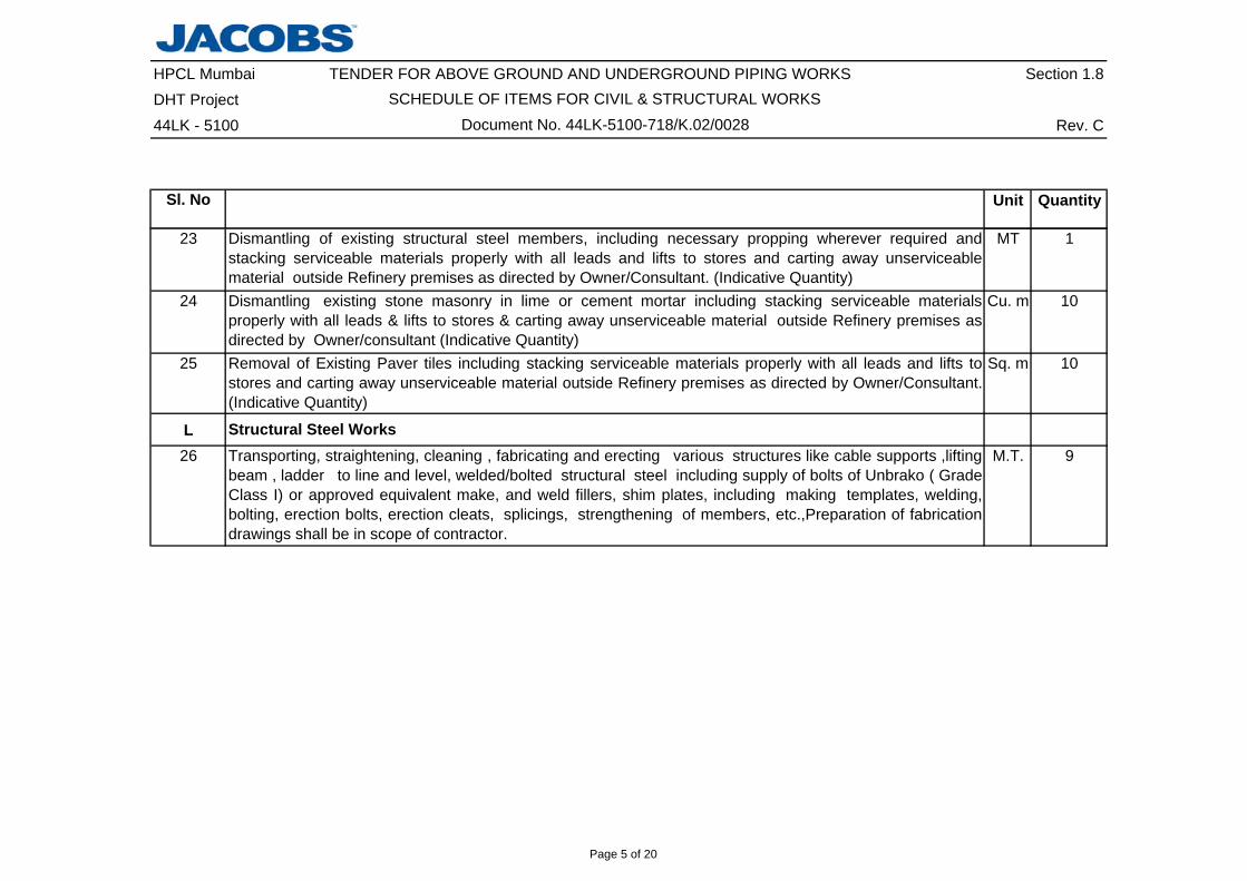
23 MT 1
24 Cu. m 10
25 Sq. m 10
L26 M.T. 9
Removal of Existing Paver tiles including stacking serviceable materials properly with all leads and lifts tostores and carting away unserviceable material outside Refinery premises as directed by Owner/Consultant.(Indicative Quantity)
Transporting, straightening, cleaning , fabricating and erecting various structures like cable supports ,liftingbeam , ladder to line and level, welded/bolted structural steel including supply of bolts of Unbrako ( GradeClass I) or approved equivalent make, and weld fillers, shim plates, including making templates, welding,bolting, erection bolts, erection cleats, splicings, strengthening of members, etc.,Preparation of fabricationdrawings shall be in scope of contractor.
Structural Steel Works
Dismantling of existing structural steel members, including necessary propping wherever required andstacking serviceable materials properly with all leads and lifts to stores and carting away unserviceablematerial outside Refinery premises as directed by Owner/Consultant. (Indicative Quantity)Dismantling existing stone masonry in lime or cement mortar including stacking serviceable materialsproperly with all leads & lifts to stores & carting away unserviceable material outside Refinery premises asdirected by Owner/consultant (Indicative Quantity)
Page 5 of 20

HPCL Mumbai TENDER FOR ABOVE GROUND AND UNDERGROUND PIPING WORKS Section 1.8DHT Project44LK - 5100 Rev. C
Sl. No Unit Quantity
SCHEDULE OF ITEMS FOR CIVIL & STRUCTURAL WORKSDocument No. 44LK-5100-718/K.02/0028
27 Sq. m 25
28 Sq. m 10
N
29 RM 40
GratingsProviding, transporting and fabricating as per the specifications, Top coated G.I.grating & treads of theapproved design and pattern and erecting & fixing of fabricated grating on operating floors, platforms, stairlandings & treads, etc., including supply of all fixtures like edge plates for treads, clips, studs, bolts, etc,including nosing for the treads etc., complete, as per drawings, specifications & as directed byOwner/Consultant. (Layout drawing to be submitted by Contractor) (Structural steel to be supplied byContractor) (weight basis = 50 Kg/m2 for grating )All gratings,nut and bolts shall be galvanized as per
30mm thick (Indicative Quantity)
Top coated hot dipped galvanized grating shall be of M.S. Steel. Galvanization shall be done in accordancewith IS 2629 & tested as per IS 2633 & IS 6745. Quality of zinc coating shall be minimum 900 g/sq.m ofsurface area .Fixing of gratings shall be by welding. Touch up repairs shall be done to portions of surfacewhere galvanizing is damaged. After galvanizing grating shall be applied with epoxy paint as per thefollowing painting system. Apply one coat of epoxy etch primer / wash primer @ 8-10 microns DFT per coat .Each primer/wash primer shall be 2 pack poly-vinyl butyal resin medium cured with phosphoric acid solutionpigmented with zinc tetroxy chromate.Apply one coat of epoxy zinc phosphate primer @ 60 microns DFT percoat . Epoxy zinc phosphate primer shall be based on Poly amide cured 2 pack epoxy with a minimum of 20% zinc phosphate by weight in the dry film. Apply one finish coat of poly-urethane paint @ 50 microns DFTper coat based on acrylic modified 2 pack poly urethane . Total DFT of paint shall be min. 118 microns abovethe zinc coating.
25mm thick
HandrailingSupplying, fabricating, erecting M.S. pipe hand railing with top rail and verticals as 40 NB & midrail as32mm NB Medium duty pipes, including bends, posts, etc., complete as per specifications, drawing & asdirected by Owner/Consultant. (Spacing of hand railing post not exceeding 1.5m)
M
Height of railing 1050mm
Page 6 of 20

HPCL Mumbai TENDER FOR ABOVE GROUND AND UNDERGROUND PIPING WORKS Section 1.8DHT Project44LK - 5100 Rev. C
Sl. No Unit Quantity
SCHEDULE OF ITEMS FOR CIVIL & STRUCTURAL WORKSDocument No. 44LK-5100-718/K.02/0028
O
30 M.T. 9
31 Rm 4032
M.T 1
P33 Each 2
34 Sq. m 3880
35 Sq. m 3880
Providing and fixing of M.S. Anchor bolts conforming to IS:2002, Grade B, in position including supply andfixing of template etc. complete , as per drawing and specification and direction of owner / consultant.
Conducting Soaked CBR test as per IS 2720 PART 31-1990 on filled up soil location as per drawing& doneas per specification & directed by owner/ consultant.
Structural Steel Painting & Shot BlastingSupplying & applying Paint to structural steel upto 15 m height for structural steel & handrailing. Workcomprises of surface preparation by Shot blasting to Sa 2 1/2 Swedish standard SIS-05-5900 & Paintingwith one coat 50 micron DFT of zinc rich epoxy(stripe coat of epoxy HB MIO) with one coat 100 DFT Midcoatof MIO 2 pack epoxy (stripe coat of HB epoxy) with one coat 100 DFT inter coat of High build 2 pack epoxy(stripe coat of acrylic aliphatic PU) with one coat 50 DFT finish coat of Acrylic Modified 2 Pack PU(Recoatable)as per specifications and drawing and as directed by the Owner/Consultant including cleaningthe surface of dust and loose particles, touching up of damaged primer coat, all labour, scaffolding, tools,consumables, etc. complete.
Providing and laying 50mm thick premixed carpet bitumen layer in two layers above the W.B.M layer of roadportion, in 35mm and 15mm thickness respectively. First layer consists of 25mm and down size stonemetal at the rate of 5.5 m3/100m2. Also inclusive of 60/70 bitumen at the rate of 260kg/100m2. Secondlayer consists of 12mm and downstone metal @ 2.0 m3/100 m2 and 60/70 bitumen of 110 kg/100 m2,including applying tackcoat consisting of 60/70 bitumen @ 100kg/100m2 thorough cleaning, spreadingnew metal as required, levelling, rolling and dressing of W.B.M. surface, heating the bitumen, mixing thesame with metal, spreading, rolling with 10 tons capacity rollers, all all materials, labour etc. complete as perdrgs. and specifications and as directed by the Owner/Consultant.
To surface of structural steel fabricated out of RSJ angles, channels, builtup sections, etc.,
To Handrailing
Providing and laying seal coat 10mm thick over premix carpet course of road portion using bitumen 60/70@ 100 kg/100 m2 of surface area and mixing with stone chips of size 6mm @ 0.92m3/100m2 of surfacearea as per correct grade and camber and rolling sufficiently with 8 to 10T smooth wheel roller etc, completeas per specifications and as directed by the Owner/Consultant.
Asphalt & Concrete road
Page 7 of 20

HPCL Mumbai TENDER FOR ABOVE GROUND AND UNDERGROUND PIPING WORKS Section 1.8DHT Project44LK - 5100 Rev. C
Sl. No Unit Quantity
SCHEDULE OF ITEMS FOR CIVIL & STRUCTURAL WORKSDocument No. 44LK-5100-718/K.02/0028
36 Cu. m 1100
37 Cu. m 1038 Cu. m 970
39 Cu. m 1040 Cu. m 235
41 Cu. m 100
42 Cu. m 80
Same as item no P 38 but with excavated metals
Same as item no P 36 but with excavated metals
Providing & laying to required camber Granular Sub-base including compacting, watering etc. complete asper drawing, specification & as directed by Engineer in Charge.
Providing & laying to required camber Granular Base wet mix macadam for road/paving portion, comprisingof coarse aggregate 53 & down size as per specification including preparation of mix in approved mixingplant with controlled addition of water ,spreading with paver finisher or motor grader & rolling with 10 M.Troller in layers of compacted thickness as per drawing.The work shall include the test involved in thespecification & other work complete as per drawing, specification & as directed by Engineer in Charge.
Providing & laying 60 mm thick Dense bituminous macadam over prepared granular base. Densebituminous macadam comprising of bitumen,coarse aggregate ,fine aggregate , anti stripping agent as perspecification , including Spreading of mix with self propelled paver finisher & rolling with 10 M.T roller, inlayer of compacted thickness as per drawing.The work shall include the test involved in the specification &other work complete as per drawing, specification & as directed by Engineer in Charge. Providing & laying 25 mm thick Semi- Dense bituminous concrete over prepared dense bituminousmacadam.Semi- Dense bituminous concrete comprising of bitumen,coarse aggregate ,fine aggregate , antistripping agent as per specification , including Spreading of mix with self propelled paver finisher & rollingwith 10 M.T roller, in layer of compacted thickness as per drawing.The work shall include the test involved inthe specification & other work complete as per drawing, specification & as directed by owner/consultant. Providing and laying plain or reinforced self-finished / broomer finish concrete of Grade M35 conforming toIS:456:2000 with 20mm and down size graded stone aggregates and mixing by mechanical mixers forroadwork in alternate bays, including tamping, compacting by internal and surface vibrators, providingsmooth shuttering, providing camber to the road surface, providing joints in the road, curing, tarring the sidesof slab with hot bitumen, proper pond curing etc., also including applying cement slurry (2.75 kg/m2) prior toplacing concrete, complete as per the drawings and specifications and as directed by the Owner/Consultant.(Reinforcement shall be paid separately).
Page 8 of 20
HPCL Mumbai TENDER FOR ABOVE GROUND AND UNDERGROUND PIPING WORKS Section 1.8DHT Project44LK - 5100 Rev. C
Sl. No Unit Quantity
SCHEDULE OF ITEMS FOR CIVIL & STRUCTURAL WORKSDocument No. 44LK-5100-718/K.02/0028
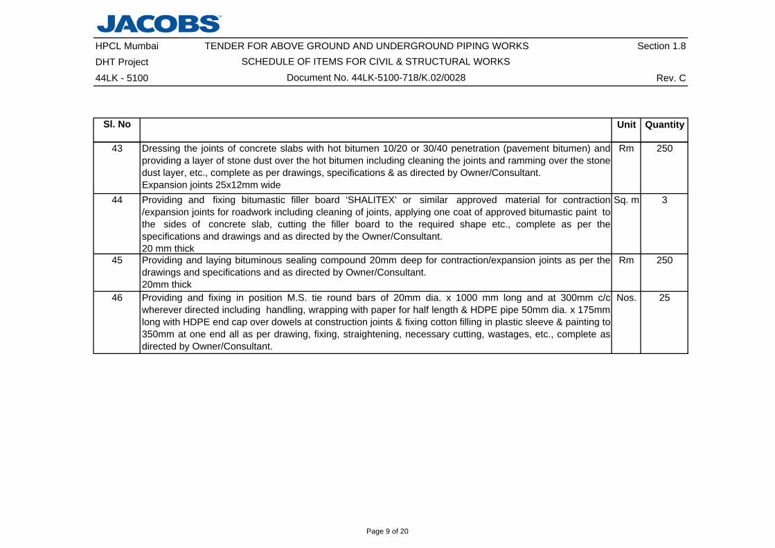
43 Rm 250
44 Sq. m 3
45 Rm 250
46 Nos. 25
Providing and laying bituminous sealing compound 20mm deep for contraction/expansion joints as per thedrawings and specifications and as directed by Owner/Consultant.20mm thick
Dressing the joints of concrete slabs with hot bitumen 10/20 or 30/40 penetration (pavement bitumen) andproviding a layer of stone dust over the hot bitumen including cleaning the joints and ramming over the stonedust layer, etc., complete as per drawings, specifications & as directed by Owner/Consultant.Expansion joints 25x12mm wideProviding and fixing bitumastic filler board ‘SHALITEX’ or similar approved material for contraction/expansion joints for roadwork including cleaning of joints, applying one coat of approved bitumastic paint tothe sides of concrete slab, cutting the filler board to the required shape etc., complete as per thespecifications and drawings and as directed by the Owner/Consultant.20 mm thick
Providing and fixing in position M.S. tie round bars of 20mm dia. x 1000 mm long and at 300mm c/cwherever directed including handling, wrapping with paper for half length & HDPE pipe 50mm dia. x 175mmlong with HDPE end cap over dowels at construction joints & fixing cotton filling in plastic sleeve & painting to350mm at one end all as per drawing, fixing, straightening, necessary cutting, wastages, etc., complete asdirected by Owner/Consultant.
Page 9 of 20

HPCL Mumbai TENDER FOR ABOVE GROUND AND UNDERGROUND PIPING WORKS Section 1.8DHT Project SCHEDULE OF ITEMS FOR PIPING & EQUIPMENT ERECTION WORKS44LK - 5100 Rev. C
Sl. No Unit Quantity
A
1 No 4
2 CS Ecentric Reducer, Thickness >10 mm and <= 20 mm, Size 32" x 30" No 2
3 No 1
B
a)b)c)d)
Item Description
Carbon Steel Aboveground Piping (Non IBR)
All work as specified in this document and relevant technical specifications as applicable.
Rates to include the followingsAll required consumables and labour, etc.
Fabrication, welding and installation of aboveground piping (as per Piping specification) including transportationof all piping items from OWNER's/CONTRACTOR's storage point, as applicable, to work site/work shop;fabrication including cutting, edge preparation, (inclusive of grinding the edges of pipe, fittings, flanges etc. tomatch with the mating edges of uneven/different thickness wherever required); fitup, bending, preheatingwherever required, welding, threading, and laying of pipes of all types and thickness over sleepers, overhead onracks and at all elevations, connecting with equipment nozzles, strainers, steam traps, orifice assemblies, spraynozzles, rotameters, tappings for pressure gauges, thermowells, sample connections, springs, sample coolersetc. and fixing of gaskets, bolts, nuts including application of torque wherever required & all other inlineinstruments and fittings, like elbows, reducers, tees,vents, drains, alignment, cleaning & flushing bywater/compressed air, hydrostatic, pneumatic, vacuum, spark testing and any other type of testing as specifieddraining, drying by compressed air, including hook-up of new lines with existing lines (if required), stacking of
CS Ecentric Reducer, Thickness >10 mm and <= 20 mm, Size 30" x 28"
Fabrication of Piping Specials from Pipes (Supplied by CONTRACTOR)
Work at all elevations including scaffolding, as required.
Fabrication of the following specials from pipes of all types & thickness including transportation of materials toContractor's storage point/ workshop, cutting, fitup, edge preparing, welding, bending, testing (including DP/MP)and inspection as per specs etc., supply of all necessary equipment, consumables, labour, supervision etc. Thework shall be carried out as per the specifications, drawings and instructions of Engineer-in-Charge.
servicable/unservicable materials and disposal of the unservicable material including return of all unused / scarppipes to OWNER's storage point, completing all such works in all respects as per the specifications, drawingsand instructions of Engineer-in-Charge.
CS Concentric Reducer, Thickness >10 mm and <= 20 mm, Size 52" x 42"
Dismantling of Special Material & instruments before hydrotest & reinstallment of the same after hydrotest.
Document No. 44LK-5100-718/K.02/0028
Page 10 of 20

HPCL Mumbai TENDER FOR ABOVE GROUND AND UNDERGROUND PIPING WORKS Section 1.8DHT Project SCHEDULE OF ITEMS FOR PIPING & EQUIPMENT ERECTION WORKS44LK - 5100 Rev. C
Sl. No Unit QuantityItem Description
Document No. 44LK-5100-718/K.02/0028
e)
f)g)
h)i)
j)
k)4 Meter 195
5 Meter 195
Material: ASTM A 106 GR.B,SMLS, ASME B-36.10, ASTM A 672 GR.B60 CL.12, EFSW, ASME B-36.1O Welded.Thickness <= 10 mm12" Pipe
Fabrication, Installation of Reinforcement pads (as per branch table included in the enquiry) & pneumatictesting of RF Pads.
Hydrotesting, Draining, Flushing, Drying, cleaning by compressed air, target Plate/Card Board Blasting, asapplicable, reinstallation of control valves, safety valves, final box up of the piping system, preparation offlange history sheet, depressurising the system, inertising the system by inert gas if required, making thesystem ready for pre commissioning.
Material: ASTM A 106 GR.B,SMLS, ASME B-36.10, ASTM A 672 GR.B60 CL.12, EFSW, ASME B-36.1O Welded.Thickness <= 10 mm16" Pipe
Supply & use of teflon tape only as jointing material for threaded/screwed connections. (If required Sealwelding for the joints also will have to be carried out).
DP Test of 10% of all weld joints by each welder.
Preparation of final marked up drawings (As Built Drawings).
Carrying out tensioning of bolted joints on all types of piping as called for in technicalspecification/instructions of Engineer-in-Charge including supply of all materials, recording devices,instruments etc.
Preparation of temporary arrangements/connections required for water flushing.
Page 11 of 20

HPCL Mumbai TENDER FOR ABOVE GROUND AND UNDERGROUND PIPING WORKS Section 1.8DHT Project SCHEDULE OF ITEMS FOR PIPING & EQUIPMENT ERECTION WORKS44LK - 5100 Rev. C
Sl. No Unit QuantityItem Description
Document No. 44LK-5100-718/K.02/0028
C
a)b)c)
d)e)f) Providing cowls/covers/temporary caps over Pipes.g)
6 Material: ASTM A 106 GR.B,SMLS,ASME B-36.10, Thickness <=10mm, 1" Pipe Meter 10
7 Material: ASTM A 106 GR.B,SMLS,ASME B-36.10, Thickness <=10mm, 1.5" Pipe Meter 10
8 Material: ASTM A 106 GR.B,SMLS,ASME B-36.10, Thickness <=10mm, 2" Pipe Meter 45
9 Material: ASTM A 106 GR.B,SMLS,ASME B-36.10, Thickness <=10mm, 12" Pipe Meter 425
10 Material: ASTM A 672 GR.B60 CL.12,EFSW,ASME B-36.10, Thickness <=10mm, 16" Pipe Meter 425
All required consumables and labour, etc.
Assembly and erection of underground piping system, including piping fittings such as Elbows, Reducers,Flanges, Tees, Half couplings, Reinforcement pad etc.
Carbon Steel Underground Piping (Non IBR)
Hydrotesting of RCC Chambers.
Preparation of final mark up and 'As Built' drawings.
Fabrication, welding and installation of underground piping (as per Piping specification) including transportationof all material from OWNER's/CONTRACTOR's storage point, as applicable, to fabrication yard/shop/work site,proper storage, cutting of pipes, if required, edge preparation, bevelling, bending, fit up, pre heating, if required,providing all branch connections, reinforcement pads, threading etc, welding all fittings and specials, erection atsite to required alignment and level, welding the same after laying, installation of flanges, tapping for otheronline instruments if required, stub connections etc. fixing of nuts and bolts, gaskets and washers, Nondestructive testing as per specification, hydrostatic testing of the system, flushing, drying the piping withcompressed air, stacking of servicable/unservicable materials and disposal of the unservicable materialincluding return of all unused / scarp pipes to OWNER's storage point.
DP Test of 10% of all weld joints by each welder.
Rates to include the followings
All work as specified in this document and relevant technical specifications as applicable.
Page 12 of 20

HPCL Mumbai TENDER FOR ABOVE GROUND AND UNDERGROUND PIPING WORKS Section 1.8DHT Project SCHEDULE OF ITEMS FOR PIPING & EQUIPMENT ERECTION WORKS44LK - 5100 Rev. C
Sl. No Unit QuantityItem Description
Document No. 44LK-5100-718/K.02/0028
D
a)b)c)
d)e)f)
11Meter 10
12Meter 40
13Meter 90
14Meter 1220
15Meter 75
Material: IS 1239-I (BLACK), DIM STD AS PER IS 1239-I, C WELDED/ IS-3589 GR.330, DIM STD AS PER IS-3589,WELDED, Thickness <= 10 mm, 6" PipeMaterial: IS 1239-I (BLACK), DIM STD AS PER IS 1239-I, C WELDED/ IS-3589 GR.330, DIM STD AS PER IS-3589,WELDED, Thickness <= 10 mm, 8" Pipe
Rates to include the followings
Assembly and erection of underground piping system, including piping fittings such as Elbows, Reducers,Flanges, Tees, Half couplings, Reinforcement pad etc.
Fabrication, welding and installation of cement lined CS underground piping (as per Piping specification)including transportation of piping items from CONTRACTOR's storage point/yard to workshop/work site insideRefinery premises, proper storage, fabrication including cutting, edge preparation, bevelling, bending, fit up, preheating, if required, providing all branch connections, reinforcement pads, threading etc, welding all fittings andspecials, erection at site in excavated trenches to required alignment and level, welding the same after laying,installation of flanges, tapping for other online instruments if required, stub connections etc. fixing of nuts andbolts, gaskets and washers, Non destructive testing as per specification, hydrostatic testing of the system,flushing, drying the piping with compressed air, stacking of servicable/unservicable materials and disposal ofthe unservicable material including return of all unused / scarp pipes to OWNER's storage point.
Material: IS 1239-I (BLACK), DIM STD AS PER IS 1239-I, C WELDED/ IS-3589 GR.330, DIM STD AS PER IS-3589,WELDED, Thickness <= 10 mm, 4" Pipe
All work as specified in this document and relevant technical specifications as applicable.
Preparation of final mark up and 'As Built' drawingsDP Test of 10% of all weld joints by each welder.
All required consumables and labour, etc.
Cement Lined Carbon Steel Underground Piping (Non IBR)
Material: IS 1239-I (BLACK), DIM STD AS PER IS 1239-I, C WELDED/ IS-3589 GR.330, DIM STD AS PER IS-3589,WELDED, Thickness <= 10 mm, 10" Pipe
Hydrotesting of RCC Chambers.
Material: IS 1239-I (BLACK), DIM STD AS PER IS 1239-I, C WELDED/ IS-3589 GR.330, DIM STD AS PER IS-3589,WELDED, Thickness <= 10 mm, 12" Pipe
Page 13 of 20

HPCL Mumbai TENDER FOR ABOVE GROUND AND UNDERGROUND PIPING WORKS Section 1.8DHT Project SCHEDULE OF ITEMS FOR PIPING & EQUIPMENT ERECTION WORKS44LK - 5100 Rev. C
Sl. No Unit QuantityItem Description
Document No. 44LK-5100-718/K.02/0028
16Meter 10
17Meter 255
18Meter 5
19Meter 10
20 Meter 10
21 Meter 25
22 Meter 15
23 Meter 190
24 Meter 25
25 Meter 1640
E
Rates to include the followingsa) All required consumables and labour, etc.b) Work at all elevations.c) Repeat inspection test due to Contractor’s fault such as weld joints requiring repair etc.
Material: IS 1239-I (BLACK), DIM STD AS PER IS 1239-I, C WELDED/ IS-3589 GR.330, DIM STD AS PER IS-3589,WELDED, Thickness <= 10 mm, 18" PipeMaterial: IS 1239-I (BLACK), DIM STD AS PER IS 1239-I, C WELDED/ IS-3589 GR.330, DIM STD AS PER IS-3589,WELDED, Thickness <= 10 mm, 20" PipeMaterial: IS 1239-I (BLACK), DIM STD AS PER IS 1239-I, C WELDED/ IS-3589 GR.330, DIM STD AS PER IS-3589,WELDED, Thickness <= 10 mm, 24" Pipe
Material: IS-3589 GR.330, DIM STD AS PER IS-3589,WELDED, Thickness > 10 mm and <= 20 mm, 30" Pipe
Material: IS-3589 GR.330, DIM STD AS PER IS-3589,WELDED, Thickness > 10 mm and <= 20 mm, 32" Pipe
Material: IS-3589 GR.330, DIM STD AS PER IS-3589,WELDED, Thickness > 10 mm and <= 20 mm, 56" Pipe
Conducting liquid penetrant test of piping weld joints over and above the 10% LPT of total welding joints byeach welder included in the scope of works for Piping, including supply of consumables, labour and supervisionas per specification and direction of Engineer-in-Charge.
Material: IS 1239-I (BLACK), DIM STD AS PER IS 1239-I, C WELDED/ IS-3589 GR.330, DIM STD AS PER IS-3589,WELDED, Thickness <= 10 mm, 16" Pipe
Material: IS-3589 GR.330, DIM STD AS PER IS-3589,WELDED, Thickness > 10 mm and <= 20 mm, 42" Pipe
Material: IS-3589 GR.330, DIM STD AS PER IS-3589,WELDED, Thickness > 10 mm and <= 20 mm, 52" Pipe
Material: IS-3589 GR.330, DIM STD AS PER IS-3589,WELDED, Thickness > 10 mm and <= 20 mm, 28" Pipe
Liquid Penetrant Inspection/Dye Penetrant Inspection
Page 14 of 20

HPCL Mumbai TENDER FOR ABOVE GROUND AND UNDERGROUND PIPING WORKS Section 1.8DHT Project SCHEDULE OF ITEMS FOR PIPING & EQUIPMENT ERECTION WORKS44LK - 5100 Rev. C
Sl. No Unit QuantityItem Description
Document No. 44LK-5100-718/K.02/0028
26 InchDia 1500
F
27 InchDia 7000
G
28 Cu.m 180
H
Rates to include the followingsa) Work at all elevations.b) Temporary arrangement required for executing the job.
Providing and supplying all required materials supported with necessary test certificates, carrying out shotblasting and painting of piping systems as per General Specification for Shop and Field Painting (44LK-5100-00-V.02-0002-04-A4) including supply of all consumables, tools, tackles, and providing covered shed etc.Completing the work in all respect as per specifications, drawings and instructions of Engineer-in-Charge.
Radiography - Weld Joints
Cement Lining
Painting of Piping
Carrying out cement lining for pipes & pipe fittings at shop (to be arranged by Contractor outside Refinerypremises) as per standard specification for Cement Lined Piping (Document No. 44LK-5100/L.02/001/A4)attached with the bidding document, completion of work in all respects as per drawing, specification &instructions of Engineers-in-Charge.
Performance of radiographic inspection on piping of all types & thickness including providing or hiring of allnecessary equipment including but not limited to necessary chemicals, films, radiographic source, cameras,penetrameters, scaffoldings, dark rooms, viewers and whatever else even though not expressly mentioned butrequired to required to perform the work as per specifications and instructions of Engineer-in-Charge.Radiograps shall be submitted to the Engineer-in-Charge. (Repeat Radiography due to CONTRACTOR's faultand for additional radiography necessitaited due to poor performance of CONTRACTOR's welders shall bedone at CONTRACTOR's cost) While taking radiographs of welds joints, overlaps are to be provided as per theapplicable Codes. Overlaps of weld length shall not be measured for billing purpose and only circumfrentialweld length of joints as calculated shall be considered for payment. No payments shall be made forRadiographs in case of weld joints require repair.
Cement Lining of Pipes & Pipe Fittings
Radiography of weld joints in pipes of various sizes
Per inch dia per pass of weld
Page 15 of 20
HPCL Mumbai TENDER FOR ABOVE GROUND AND UNDERGROUND PIPING WORKS Section 1.8DHT Project SCHEDULE OF ITEMS FOR PIPING & EQUIPMENT ERECTION WORKS44LK - 5100 Rev. C
Sl. No Unit QuantityItem Description
Document No. 44LK-5100-718/K.02/0028
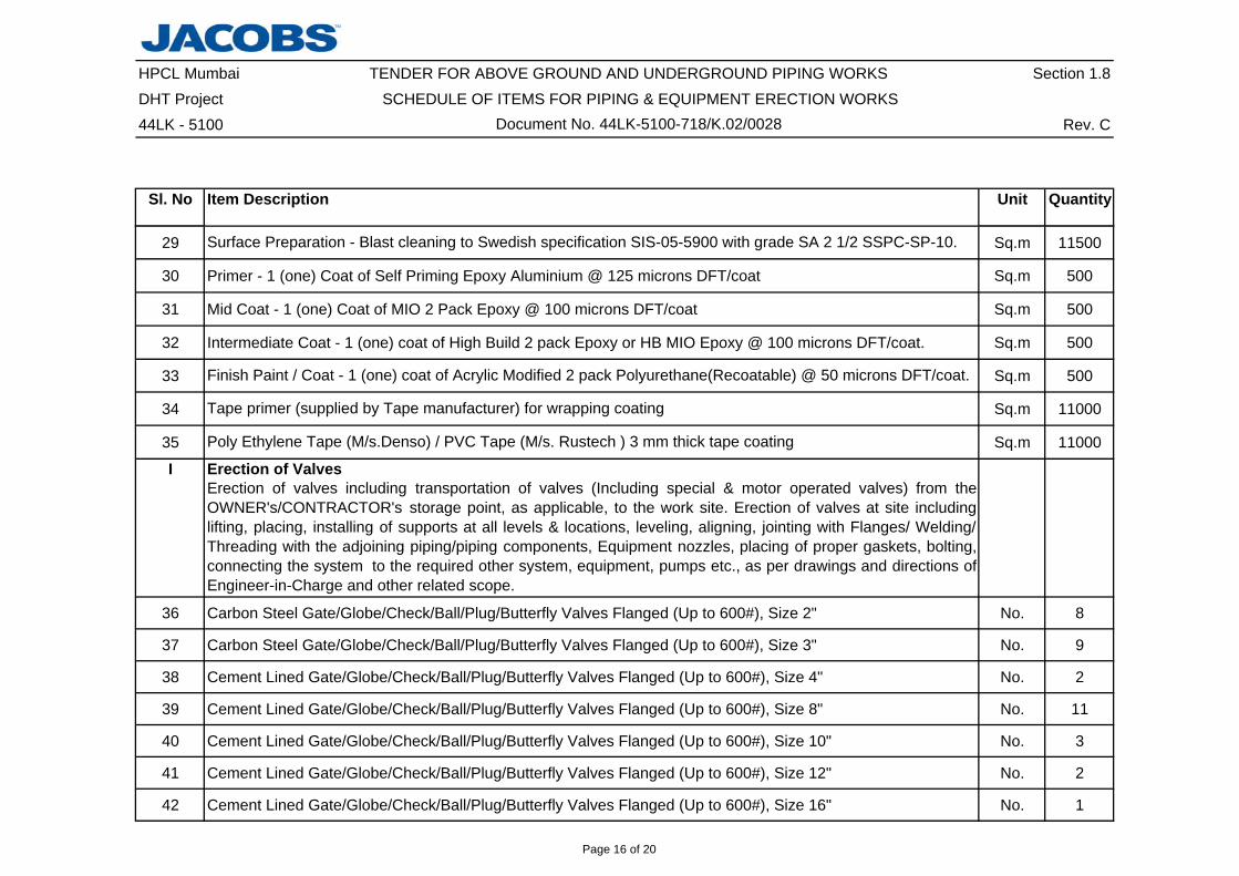
29 Sq.m 11500
30 Primer - 1 (one) Coat of Self Priming Epoxy Aluminium @ 125 microns DFT/coat Sq.m 500
31 Mid Coat - 1 (one) Coat of MIO 2 Pack Epoxy @ 100 microns DFT/coat Sq.m 500
32 Intermediate Coat - 1 (one) coat of High Build 2 pack Epoxy or HB MIO Epoxy @ 100 microns DFT/coat. Sq.m 500
33 Sq.m 500
34 Sq.m 11000
35 Sq.m 11000
I Erection of Valves
36 Carbon Steel Gate/Globe/Check/Ball/Plug/Butterfly Valves Flanged (Up to 600#), Size 2" No. 8
37 Carbon Steel Gate/Globe/Check/Ball/Plug/Butterfly Valves Flanged (Up to 600#), Size 3" No. 9
38 Cement Lined Gate/Globe/Check/Ball/Plug/Butterfly Valves Flanged (Up to 600#), Size 4" No. 2
39 Cement Lined Gate/Globe/Check/Ball/Plug/Butterfly Valves Flanged (Up to 600#), Size 8" No. 11
40 Cement Lined Gate/Globe/Check/Ball/Plug/Butterfly Valves Flanged (Up to 600#), Size 10" No. 3
41 Cement Lined Gate/Globe/Check/Ball/Plug/Butterfly Valves Flanged (Up to 600#), Size 12" No. 2
42 Cement Lined Gate/Globe/Check/Ball/Plug/Butterfly Valves Flanged (Up to 600#), Size 16" No. 1
Erection of valves including transportation of valves (Including special & motor operated valves) from theOWNER's/CONTRACTOR's storage point, as applicable, to the work site. Erection of valves at site includinglifting, placing, installing of supports at all levels & locations, leveling, aligning, jointing with Flanges/ Welding/Threading with the adjoining piping/piping components, Equipment nozzles, placing of proper gaskets, bolting,connecting the system to the required other system, equipment, pumps etc., as per drawings and directions ofEngineer-in-Charge and other related scope.
Poly Ethylene Tape (M/s.Denso) / PVC Tape (M/s. Rustech ) 3 mm thick tape coating
Tape primer (supplied by Tape manufacturer) for wrapping coating
Finish Paint / Coat - 1 (one) coat of Acrylic Modified 2 pack Polyurethane(Recoatable) @ 50 microns DFT/coat.
Surface Preparation - Blast cleaning to Swedish specification SIS-05-5900 with grade SA 2 1/2 SSPC-SP-10.
Page 16 of 20

HPCL Mumbai TENDER FOR ABOVE GROUND AND UNDERGROUND PIPING WORKS Section 1.8DHT Project SCHEDULE OF ITEMS FOR PIPING & EQUIPMENT ERECTION WORKS44LK - 5100 Rev. C
Sl. No Unit QuantityItem Description
Document No. 44LK-5100-718/K.02/0028
43 Cement Lined Gate/Globe/Check/Ball/Plug/Butterfly Valves Flanged (Up to 600#), Size 18" No. 4
44 Cement Lined Gate/Globe/Check/Ball/Plug/Butterfly Valves Flanged (Up to 600#), Size 24" No. 1
45 Cement Lined Gate/Globe/Check/Ball/Plug/Butterfly Valves Flanged (Up to 600#), Size 30" No. 6
46 Cement Lined Gate/Globe/Check/Ball/Plug/Butterfly Valves Flanged (Up to 600#), Size 32" No. 3
47 Cement Lined Gate/Globe/Check/Ball/Plug/Butterfly Valves Flanged (Up to 600#), Size 42" No. 1
48 Carbon Steel Gate/Globe/Check/Ball/Plug Valves SCRF (800# and above), Size 0.5" No. 28
49 Carbon Steel Gate/Globe/Check/Ball/Plug Valves SCRF (800# and above), Size 0.75" No. 16
50 Carbon Steel Gate/Globe/Check/Ball/Plug Valves SCRF (800# and above), Size 1" No. 4
J
a) All required consumables and labour, etc.b)c) Supply of materials like packers, sleeves, grouting materials etc.d) Supports for all types of Pipes.e) Site welding and modification during erection, if required.
51 Pipe Supports - Rolled Section of Carbon Steel (IS: 2062) MT 1052 MT 2Same as Item No. J 51 above but without supply of structural steel and using pipes (Free issue material) for
trunion supports. Quoted rates to include collection of material from OWNER's storage point.
Work at all elevations.
Pipe SupportsFabrication of pipe supports like shoes, cradles, hangers, clamps (of all sizes/thicknesses manufactured byforming method using die), turn buckles, saddles, guides, special supports, pads, T post etc. of all types,Erection(at all elevations) including all necessary equipments, consumables, labour, returning surplus materialsand scrap etc. to OWNER's storage points and completing work as per drawings, specifications and instructionsof Engineer-in-charge. Rates to include the followings
Page 17 of 20

HPCL Mumbai TENDER FOR ABOVE GROUND AND UNDERGROUND PIPING WORKS Section 1.8DHT Project SCHEDULE OF ITEMS FOR PIPING & EQUIPMENT ERECTION WORKS44LK - 5100 Rev. C
Sl. No Unit QuantityItem Description
Document No. 44LK-5100-718/K.02/0028
K
53 MT 10
L
54 MT 10
M
55 MT 10
N
56 MT 10
Supplying, Cleaning the surface of dust and loose particles, touching up of damaged primer coat, including alllabour, scaffolding, tools, consumables & applying 1 (one) coat of High Build 2 pack Epoxy or HB MIO Epoxy @100 microns DFT/coat of approved make & quality and colour / shade as per drawings, specifications & asdirected by the Engineer-in-Charge.
Pipe Supports - Rolled Section of Carbon Steel (IS: 2062)
Finish PaintSupplying, Cleaning the surface of dust and loose particles including all labour, scaffolding, tools, consumables& applying 1 (one) coat of Acrylic Modified 2 pack Polyurethane(Recoatable) @ 50 microns DFT/coat ofapproved make & quality and colour / shade as per drawings, specifications & as directed by the Engineer-in-Charge.
Pipe Supports - Rolled Section of Carbon Steel (IS: 2062)
Pipe Supports - Rolled Section of Carbon Steel (IS: 2062)
Intermediate Coat
Surface Preparation & PrimerSurface Preparation of fabricated pipe supports and spring supports by Blast Cleaning as per Swedish standard-SIS-05 5900 (SA 2 1/2) & applying shop primer 1 (one) Coat of Zn Rich Epoxy @ 50 microns DFT/coat ofapproved make as per specifications & as directed by the Engineer-in-Charge.
Pipe Supports - Rolled Section of Carbon Steel (IS: 2062)
Mid CoatSupplying, Cleaning the surface of dust and loose particles, touching up of damaged primer coat, including alllabour, scaffolding, tools, consumables & applying 1 (one) Coat of MIO 2 Pack Epoxy @ 100 microns DFT/coatof approved make & quality and colour / shade as per drawings, specifications & as directed by the Engineer-in-Charge.
Page 18 of 20

HPCL Mumbai TENDER FOR ABOVE GROUND AND UNDERGROUND PIPING WORKS Section 1.8DHT Project SCHEDULE OF ITEMS FOR PIPING & EQUIPMENT ERECTION WORKS44LK - 5100 Rev. C
Sl. No Unit QuantityItem Description
Document No. 44LK-5100-718/K.02/0028
O Erection of Rotary Equipment
57 All type of Pumps with Drivers and all accessories. MT 65
P Anchor Fastners
58 8 mm Diameter, 100 mm Long No 50
59 10 mm Diameter, 100 mm Long No 50
60 12 mm Diameter, 100 mm Long No 50
61 8 mm Diameter, 150 mm Long No 50
62 10 mm Diameter, 150 mm Long No 50
63 12 mm Diameter, 150 mm Long No 50
Q
Providing and fixing Electroplated Steel (heavy duty) Mechanical Anchor Fastners of Hilti or approvedequivalent and installed as per manufacturer’s specification, drawing and as directed by Engineer-in-Charge.
Transportation of Rotating Equipment & miscellaneous items from OWNER’s storage points to worksite/CONTRACTOR's stores/location shown in the equipment layouts or plot plans, unloading, unloading ofequipments at their respective places wherever direct installation is possible, assembly of sub-assemblies,placing the equipments on foundations including chipping & dressing of foundations, grouting (including supplyand application of non-shrink grout material) providing and placing packing, shims, leveling, alignment ofequipment with pipe and without pipe, bolt tightening and final alignment of equipment, preparation for no loadrun, flushing and filling of lubricant, replacement of gland packing with mechanical seals, completing the work inall respects as per drawings, technical specifications and instructions of Engineer-in-Charge till satisfactory startup, test run and hand over.
Modification WorksCutting, bevelling, fitup, welding of different sizes of CS(IBR/NON IBR)/AS IBR/SS/Cladded piping of all typesand thicknessess in shop, in position, on ground/overhead on rack and at all elevations; transportation of pipes,fittings, flanges etc from owner's storage point to work site/ work shop, making necessary scaffoldings,consumables, machinery, tools, tackles, labour and supervision including attending repairs for completing thework as per the instruction of Engineer-in-Charge.
Page 19 of 20

HPCL Mumbai TENDER FOR ABOVE GROUND AND UNDERGROUND PIPING WORKS Section 1.8DHT Project SCHEDULE OF ITEMS FOR PIPING & EQUIPMENT ERECTION WORKS44LK - 5100 Rev. C
Sl. No Unit QuantityItem Description
Document No. 44LK-5100-718/K.02/0028
64 InchDia 500
65 InchDia 1000
66 InchDia 1250
R
This manpower shall be deployed only against specific instruction of the Engineer-in-Charge. The quoted rates shall be used for the services not included in the scope of work of the contractor.
67 Man-day 100
68 Man-day 100
69 Man-day 100
70 Man-day 50
Flame Cutting CS Piping IBR/Non IBR
Khalasi/Helper/Unskilled Worker/Gas Cutter/Painter/Grinder
Fitup and Welding CS Piping IBR/Non IBR
Bevelling CS Piping IBR/Non IBR
Millwright Fitter /Tig Welder
Manpower SupplyProviding skilled/unskilled manpower with all the tools & tackles, consumables, brooms, dial indicators, laseralignment instruments, supervision, safety, PPEs etc. for carrying out activities assigned by Owner/Engineer-in-Charge and completing the work as per the instruction. One Shift/Man-day consisting of 12 hrs per day. Quotedrates shall be inclusive of PPEs, wages, allowances, taxes, overheads, necessary supervision etc
Fitter/Skilled Manpower/ Welder etc
Rigger
Page 20 of 20

\\nmumfil01\Construction\44LK 5100 HPCL DHT\Civil & Structural Works - OSBL\Inputs\osbl tender\Standard specificatios\Specifications for Earthwork_1101.doc
Page 1 of 7
HINDUSTAN PETROLEUM CORPORATION LIMITED MUMBAI REFINERY
DHT PROJECT – OSBL FACILITIES
TITLE : SPECIFICATIONS FOR EARTHWORK
DOCUMENT NO. : 44LK-5100-00/C.02/1101/A4
Rev No. Issue Date Pages Rev Description Prepared
By
Checked
By
Approved
By
A 25/10/2008 7 ISSUED FOR TENDER DK SSP MBR
Jacobs Pages 2 of 7 Specification for Earthwork HPCL, Mumbai Standard Specification 44LK5100 Doc.no.44LK-5100-00/C.02/1101/A4
\\nmumfil01\Construction\44LK 5100 HPCL DHT\Civil & Structural Works - OSBL\Inputs\osbl tender\Standard specificatios\Specifications for Earthwork_1101.doc
TABLE OF CONTENTS 1.0 PURPOSE 2.0 SCOPE 3.0 TECHNICAL REQUIREMENTS 3.1 CLASSIFICATION OF SOIL 3.1.1 Soft / Loose Soil 3.1.2 Hard / Dense Soil 3.1.3 Soft / Disintegrated Rock 3.1.4 Hard Rock ( General Blasting Permitted) 3.1.5 Hard Rock (Old Controlled Blasting Permitted) 3.1.6 Hard Rock (Blasting Prohibited) 3.2 MATERIAL FOR BACKFILLING 3.3 SETTING OUT 3.4 EARTHWORK IN EXCAVATION 3.5 BLASTING IN HARD ROCK 3.6 SHORING AND STRUTTING 3.6.1 General 3.7 BACKFILLING IN PLINTHS AND AROUND FOUNDATIONS 3.7.1 General 3.8 DISPOSAL OF SURPLUS EARTH 3.8.1 General 3.9 SANDFILLING IN PLINTHS AND FOUNDATIONS 3.9.1 General 3.10 HARD CORE / RUBBLE SOLING 3.10.1 General

Jacobs HPCL, Mumbai Specification for Earthwork Pages 3 of 7 44LK5100 Standard Specification Doc.no.44LK-5100-00/C.02/1101/A4
\\nmumfil01\construction\44lk 5100 hpcl dht\civil & structural works - osbl\inputs\osbl tender\standard specificatios\specifications for earthwork_1101.doc
1.0 PURPOSE The purpose of this standard is to define specifications to be followed for Earthwork.
2.0 SCOPE
This Specification establishes the classification of soils, constructional and performance requirements for earthwork in excavation and filling. In case of conflict between the clauses of this specification and those in the Indian Standards, this specification shall govern.
3.0 TECHNICAL REQUIREMENTS 3.1 CLASSIFICATION OF SOIL The various types of soil shall be classified as follows: 3.1.1 Soft / Loose Soil This shall be all those soils, which yield to the ordinary application of, pick and shovel, rake or any
other ordinary digging implement. Soils such as gravel, sand, silt, loam, clay, peat, vegetable or organic soil, turf etc. are included in this classification.
3.1.2 Hard / Dense Soil This shall include soils, which require the close application of pick, jumper or scarifier to loosen
them. Stiff clays, gravels and cobble stones are included in such soils. 3.1.3 Soft / Disintegrated Rock This classification shall include laterite and hard conglomerate. Rocks or boulders than can be
quarried or split with a crowbar shall also be included. 3.1.4 Hard Rock (General Blasting Permitted) This classification shall include Rocks and Boulders that require blasting for excavation. 3.1.5 Hard Rock (Old Controlled Blasting Permitted) Hard rocks that require blasting, but for the excavation of which general blasting is prohibited for
any reason, shall be included in this category. The method of controlled blasting shall be subject to the approval of Owner / Consultant.
3.1.6 Hard Rock (Blasting Prohibited) This shall include hard rocks that require blasting for excavation (i.e. as in category included at
3.1.5) but where blasting is prohibited due to any reason and hence excavation has to be carried out by chiseling, wedging or any other approved method.
3.2 MATERIAL FOR BACKFILLING
Material used in the backfilling of excavation in foundations, trenches and elsewhere shall consist of any one of the following materials in each location.
a) Soil b) Stone / gravel c) Sand d) Lean Concrete e) Selected earth from heaps or brought from borrows areas

Jacobs Pages 4 of 7 Specification for Earthwork HPCL, Mumbai Standard Specification 44LK5100 Doc.no.44LK-5100-00/C.02/1101/A4
\\nmumfil01\Construction\44LK 5100 HPCL DHT\Civil & Structural Works - OSBL\Inputs\osbl tender\Standard specificatios\Specifications for Earthwork_1101.doc
The material shall be free of roots, hard lumps, rubbish or any foreign organic material. All material shall be used only after the approval of Owner / Consultant.
3.3 SETTING OUT The contractor shall be responsible for the accurate and proper setting out of the work with
regard to lines and levels of reference, and with regard to the correctness of dimensions, alignments and levels of the work. The contractor shall, at his own cost, provide all necessary instruments, labour, material and equipment for this purpose. Should any error be discovered, at any time, during the progress of work or thereafter, in the dimensions, alignment or level of part or all of work, the contractor shall at his own expense rectify the errors to the satisfaction of the Owner / Consultant. Any checking of line or level by the Owner / Consultant shall in no way relieve the contractor of his responsibilities.
The contractor shall prior to start of work layout one or more permanent bench marks at a central
location from which all levels for the earthwork shall be set. All labour and materials for setting levels shall be at contractor's cost. Permanent benchmarks shall be made up of masonry pillars with a neatly plastered top and leveled as per the directions of Owner / Consultant. The benchmarks shall be well connected with a triangular grid system or other bench marks and the entire arrangement approved by the Owner / Consultant.
3.4 EARTHWORK IN EXCAVATION Excavation shall be carried out to the lines and levels shown on drawing and the excavated
material shall be removed to soil heaps on site or transported for use in filing on the site or otherwise stacked for reuse as directed.
The sides of the excavation may, depending upon the site conditions pertaining at that time, be
cut vertical, sloping or shored and strutted to hold the face of the earth as approved and directed by Owner / Consultant.
The contractor shall remove all vegetation etc. obtained during excavation. Excavated material shall not be deposited closer than 1.5 M from the top edge of the excavation. Foundation pits / trenches shall be excavated to a depth 150 mm short of the full depth. The final
150mm shall be excavated just prior to concreting. Alternately and at the discretion of the Owner / Consultant the full depth may be excavated and the bed covered with a 75 mm thick layer of lean concrete of 1:5:10 nominal mix. (Or of such thickness and mix as are specified on drawings) after compacting the sub base.
If the bottom of the excavation, has in the opinion of the Owner / Consultant, deteriorated due to
exposure to water or atmosphere, the contractor shall remove the deteriorated material to such depth and width as directed by the Owner / Consultant and shall replace the same with lean concrete of 1:5:10 mix. The costs of all such excavation and concreting shall be borne by contractor.
In case contractor excavates to a depth greater than the depth required, the contractor shall at his
own expense fill upto required level with lean concrete 1:5:10 mix or as directed by the Owner / Consultant.
The contractor shall at his own cost provide suitable drainage arrangement to prevent surface
water from any source, from entering the excavation. The contractor shall at his own cost make all arrangements necessary for dewatering the
accumulated / seeping water, from any source, in the excavated pits, trenches etc. for maintaining the pit dry for carrying out the works.

Jacobs HPCL, Mumbai Specification for Earthwork Pages 5 of 7 44LK5100 Standard Specification Doc.no.44LK-5100-00/C.02/1101/A4
\\nmumfil01\construction\44lk 5100 hpcl dht\civil & structural works - osbl\inputs\osbl tender\standard specificatios\specifications for earthwork_1101.doc
In case of excavation to be carried out adjacent and below the foundation level of adjoining
structures, precautionary measures as directed by Owner / Consultant, such as pinning, shoring and strutting shall be carried out, prior to commencing excavations.
In case the bottom of excavation at the required level is in the opinion of the Owner / Consultant
unsuitable due to being soft or loose soil, the excavation shall be continued to a firm and suitable ground and the difference in levels made up with lean concrete of grade 1:5:10.
In case where during excavation the sides collapse due to a reason not attributable to the
contractor, the Owner / Consultant shall at his discretion admit payment for any additional resultant excavation.
Any obstacles such as buried pipes, cables etc. met with during excavation shall be reported to
the Owner / Consultant who shall give directions regarding protection / removal of the same. The contractor at his own expense shall take all measures necessary to prevent accidents on
account of open excavations such as fencing, lighting and other suitable preventive measures. Concreting in foundations shall not commence prior to the excavations being approved by the
Owner / Consultant. For excavation in rock the specification of earthwork shall apply. Special care shall be taken to
prevent excavations beyond the width / depth required when excavating in rock. Any additional depth excavated shall be compensated by filling with lean concrete 1:5:10 at no additional cost to the owner.
3.5 BLASTING IN HARD ROCK
Where hard rock requiring blasting is encountered the contractor shall inform the owner / consultant and seek his approval. The contractor shall obtain a license from the District Authorities for obtaining, storing the explosives and for carrying out blasting operations as per Explosives Rules 1940 and as amended till date. The contractor shall buy all explosives, fuses, and detonators from licensed dealers only. Prior to the use of such explosives, the contractor shall be liable for their secure custody and accounting. The Owner / Consultant shall be provided access to check the contractors stock and accounts. The contractor shall be solely responsible for any accident or mishap to workmen, life or property due to blasting operations.
Blasting shall not be done within 200m of an existing (previously constructed or under construction) structure without the specific approval of the Owner / Consultant for such close proximity operation.
All blasting shall be carried out by trained personnel under the supervision of a responsible
authorised agent of the contractor, who is conversant with all the rules for blasting. Blasting shall be carried out during specified hours only. Proper precautions shall be taken to ensure safety during such operations such as providing red flags prominently displayed around the area to be blasted and securing the withdrawal of all personnel, apart from these lighting the fuse, to a safe distance of not less than 200 meters from the blast.
Blasting shall be carried out using gunpowder. Gelatine or dynamite or any other high explosive
shall only be used in special cases and with the approval of Owner / Consultant. 3.6 SHORING AND STRUTTING 3.6.1 General Shoring and strutting of the sides to hold the vertical / inclined faces of the pits and trenches shall
only be done when so approved and directed by Owner / Consultant.

Jacobs Pages 6 of 7 Specification for Earthwork HPCL, Mumbai Standard Specification 44LK5100 Doc.no.44LK-5100-00/C.02/1101/A4
\\nmumfil01\Construction\44LK 5100 HPCL DHT\Civil & Structural Works - OSBL\Inputs\osbl tender\Standard specificatios\Specifications for Earthwork_1101.doc
The shoring shall be of close or open timbering type based on the site conditions and subject to the approval of the Owner / Consultant.
The strutting shall not be spaced more than 1.5 m apart and the shoring planks shall be held tight
by means of wedges. The arrangements of shoring and strutting shall be got approved from the Owner / Consultant prior to start of work. The arrangement shall be sound and safe and any approval obtained from Owner / Consultant shall not reduce the responsibility of the contractor in any manner.
The shoring and strutting shall be kept in position until all the work involving the excavation is
completed and approved by the Owner / Consultant. 3.7 BACKFILLING IN PLINTHS AND AROUND FOUNDATIONS / FILLING 3.7.1 General
Backfilling around completed foundations, pits, structures, trenches and in plinth shall be carried out to the levels and lines shown on the drawings, including any trimming of the surface where required.
The backfilling shall be carried out with selected and approved excavated material or in case the
excavated earth does not yield sufficient quantity of suitable material, suitable earth from other sources shall be imported upon the instruction of the Owner / Consultant.
The filling shall be done in layers of 200 mm (maximum) compacted thickness. Each layer shall
be watered, rolled and rammed using manual methods or mechanical compactors to obtain 90% Proctor density.
Filling under slabs / paving / roads / tanks etc shall be done as per the compaction requirements specified for the item.
Backfilling around liquid retaining structures shall be undertaken only after satisfactory completion
and approval of hydrotest. Backfilling around pipes shall be done only after the Owner / Consultant has approved the results of testing against leakage.
Backfilling work around structures shall be taken up only after obtaining permission of Owner /
Consultant. 3.8 DISPOSAL OF SURPLUS EARTH 3.8.1 General
Surplus earth and soil from excavation shall be removed from the construction area to the area out side the refinery premises in BMC approved land as directed by the Owner / Consultant.
3.9 SANDFILLING IN PLINTHS AND FOUNDATIONS 3.9.1 General The sand used for filling shall be clean, hard and free from organic, deleterious matter and dust
and shall be approved by Owner / Consultant. Filling shall be carried out in layers of maximum thickness 200 mm compacted and shall be
compacted either mechanically or by saturation to obtain 95% Modified Proctor maximum dry density to the specified level. Compaction by flooding may be permitted at the discretion of the Owner / Consultant provided the required compaction is achieved.
Filling in and around any work shall commence only after obtaining the permission of Owner /
Consultant.

Jacobs HPCL, Mumbai Specification for Earthwork Pages 7 of 7 44LK5100 Standard Specification Doc.no.44LK-5100-00/C.02/1101/A4
\\nmumfil01\construction\44lk 5100 hpcl dht\civil & structural works - osbl\inputs\osbl tender\standard specificatios\specifications for earthwork_1101.doc
3.10 HARD CORE / RUBBLE SOLING 3.10.1 General
Hard core shall be of broken stones, which are sound, hard and free from dust, flakes and other impurities.
Hard core shall be laid by placing broken stones of required height vertically. Interspaces shall be
hand packed with smaller sized stones followed by blinding with approved quality murrum / sand. Consolidation shall be done with a rammer / roller in conjunction with watering. The hard core shall be dressed to the specified grade, level and thickness.

\\nmumfil01\Construction\44LK 5100 HPCL DHT\Civil & Structural Works - OSBL\Inputs\osbl tender\Standard specificatios\Specifications for Plain and Reinforced Cement
Concrete_1102.doc
Page 1 of 18
HINDUSTAN PETROLEUM CORPORATION LIMITED
MUMBAI REFINERY
DHT PROJECT – OSBL FACILITIES
TITLE : SPECIFICATIONS FOR PLAIN AND
REINFORCED CEMENT CONCRETE
DOCUMENT NO. : 44LK-5100-00/S.02/1102/A4
Rev No. Issue Date Pages Rev Description Prepared
By
Checked
By
Approved
By
A
25/10/2008 18 ISSUED FOR TENDER DK SSP MBR

Jacobs
Pages 2 of 18 Specification for Plain & Reinforced Cement Concrete HPCL, Mumbai
Standard Specification 44LK5100
Doc.no.44LK-5100-00/S.02/1102/A4
\\nmumfil01\Construction\44LK 5100 HPCL DHT\Civil & Structural Works - OSBL\Inputs\osbl tender\Standard specificatios\Specifications for Plain and Reinforced Cement
Concrete_1102.doc
TABLE OF CONTENTS
1.0 PURPOSE
2.0 SCOPE
3.0 TECHNICAL REQUIREMENTS
3.1 MATERIALS
3.2 TYPES AND GRADES
3.3 PROPORTIONING
3.4 MIXING
3.5 REINFORCEMENT : CUTTING, BENDING, PLACING AND FIXING
3.6 TRANSPORTATION AND PLACING
3.7 COMPACTION
3.8 EMBEDDED ITEMS IN CONCRETE
3.9 CONSTRUCTION JOINTS
3.10 CURING
3.11 PROTECTION OF IMMATURE CONCRETE
3.12 CUBE TESTING FOR STRENGTH OF CONCRETE
3.13 TESTING OF STRUCTURES
3.14 FINISHING TO CONCRETE
3.15 MINOR REPAIR OF DEFECTIVE CONCRETE
3.16 GROUTING
3.17 FORMWORK
3.18 STAGING / SCAFFOLDING
3.19 PRECAST CONCRETE
4.0 RELATED DOCUMENTATION
5.0 ATTACHMENTS

Jacobs
HPCL, Mumbai Specification for Plain & Reinforced Cement Concrete Pages 3 of 18
44LK5100 Standard Specification
Doc.no.44LK-5100-00/S.02/1102/A4
\\nmumfil01\Construction\44LK 5100 HPCL DHT\Civil & Structural Works - OSBL\Inputs\osbl tender\Standard specificatios\Specifications for Plain and Reinforced Cement
Concrete_1102.doc
1.0 PURPOSE The purpose of this document is to state the requirements of material, workmanship and
construction procedure to be followed during the execution of plain and reinforced cement concrete works.
2.0 SCOPE
This specification establishes the requirements of materials, mixing, placing, curing etc. of all types of concrete, cast-in-situ as well as precast, used in various structures, at any locations such as foundations, floors, roofs, tanks, etc., both above ground and underground. Any special requirements as shown or noted on the drawings shall govern over the provisions of this specification.
2.1 The construction of plain and reinforced concrete works shall also be in accordance with IS:456
and the other codes mentioned therein. In case of conflict between the clauses of this specification and those in the IS:456, this specification shall govern.
3.0 TECHNICAL REQUIREMENTS 3.1 MATERIALS 3.1.1 Aggregate a. General
Coarse and fine aggregate for concrete shall conform to IS:383. Aggregates shall consist of sand, gravel, stones, either crushed or uncrushed, or a suitable combination of them. Aggregates shall be obtained from a source known to produce aggregates satisfactory for concrete. The source of the aggregate shall be approved by the Owner / Consultant. The aggregates shall be chemically inert, strong, hard, dense, durable, clean and free of adherent coatings, vegetable matter, injurious amounts of alkalis and other deleterious substances. Elongated and flaky pieces shall not be used. When directed by the Owner / Consultant, the aggregates shall be washed by the contractor before use in the works. Washing of aggregates shall be done away from the project site.
b. Deleterious Materials
The aggregates shall not contain harmful materials that affect the strength or durability of concrete or cause corrosion of the reinforcement. Materials that could have such adverse effects are iron, pyrites, coal, lignite, mica, shale or similar laminated material, clay, soft fragments, sulphates, chlorides, sea shells, organic impurity etc. Further aggregates that react with the alkalis of cement shall not be used. Materials that pass 75 micron IS sieve shall also be classified as deleterious. The total of all deleterious materials present in coarse aggregate, crushed or uncrushed, and in uncrushed fine aggregate shall not exceed five percent by weight, whereas for crushed fine aggregates it shall not exceed two percent by weight. The quantities of deleterious materials in the aggregates shall be determined in accordance with IS:2386 (Part II) - Methods of test for aggregates for concrete. The maximum quantities shall not exceed the limits defined in Table 1 of IS:383.

Jacobs
Pages 4 of 18 Specification for Plain & Reinforced Cement Concrete HPCL, Mumbai
Standard Specification 44LK5100
Doc.no.44LK-5100-00/S.02/1102/A4
\\nmumfil01\Construction\44LK 5100 HPCL DHT\Civil & Structural Works - OSBL\Inputs\osbl tender\Standard specificatios\Specifications for Plain and Reinforced Cement
Concrete_1102.doc
c. Fine Aggregates
Fine aggregate is the aggregate which passes 4.75 mm IS sieve, but of which only a maximum of 10% passes through 150 micron I.S. sieve. The fine aggregate shall conform to the requirements of grading Zones I, II and III given in table 4 of IS 383. Fine aggregates conforming to grading Zone IV shall not normally be used, unless tests have been made by the contractor to determine the suitability of the aggregate with the proposed mix proportions and are duly approved by the Owner / Consultant. The grading of fine aggregates shall be determined in accordance with IS-2386 (Pt.1). Fine aggregates shall consist of natural sand obtained due to the natural disintegration of rock and which is deposited by rivers, streams or glacial agencies, or crushed stone sand or crushed gravel sand. the use of sea sand shall not be allowed. The source of sand shall also be free from the tidal effects of backwaters of sea.
The volume of sand used in nominal mixes shall be adjusted to cater for the effects of bulking when measurement is by loose volume. The percentage bulking shall be determined by laboratory tests as and when directed by the Owner / Consultant.
d. Coarse Aggregate
Coarse aggregate is aggregate, most of which is retained on 4.75 mm I.S. sieve. It shall have a specific gravity (saturated surface dry basis) of not less than 2.6 coarse aggregates shall consist of crushed or uncrushed stone or gravel conforming to above mentioned clauses. They may be supplied as single sized or as graded aggregates conforming to table 1 of IS:383. The use of "All-in-Aggregates" may be permitted by the Owner / Consultant provided they meet the requirements of IS:383. Rounded aggregates such as gravel, shall be preferred over angular varieties.
e. Sampling and Testing
The Owner / Consultant may require the contractor to carry out tests at the contractors expense, in accordance with IS-2386 - Methods of test for aggregates of concrete. Sampling shall be carried out as per IS-2430.
f. Storage of Aggregates
The contractor shall at all times maintain sufficient quantities of fine and coarse aggregates so as to permit placement at the required rate. The aggregate shall be stored on hard, firm ground having sufficient slope to provide adequate drainage to water. All necessary care shall be taken to prevent the intrusion of foreign matter. Aggregate shall be stored at site in such a manner so as to obtain segregation based on type, grade and source. Any aggregate becoming wet at site due to rain or other means, or delivered wet shall not be used for at least twenty four hours to obtain adequate drainage. Alternately, the water content of the mix shall be suitably adjusted and the same approved by the Owner / Consultant.
3.1.2 Cement a. General
Cement shall be ordinary Portland cement conforming to IS:269-1989 for grade 33 cement, IS:8112-1989 for grade 43 cement, IS 12269 for grade 53 cement, hydrophobic cement conforming to IS:8043, Portland Slag cement conforming to IS:455 or Sulphate Resistant cement conforming to IS:12330, as specified, or as directed by the Owner / Consultant. Portland Pozzolana cement, when permitted by Owner / consultant shall conform to IS:1489. High Alumina
Jacobs
HPCL, Mumbai Specification for Plain & Reinforced Cement Concrete Pages 5 of 18
44LK5100 Standard Specification
Doc.no.44LK-5100-00/S.02/1102/A4
\\nmumfil01\Construction\44LK 5100 HPCL DHT\Civil & Structural Works - OSBL\Inputs\osbl tender\Standard specificatios\Specifications for Plain and Reinforced Cement
Concrete_1102.doc
cement, conforming to IS:6452 shall be used only if specified and in accordance with manufacturer's recommendations. Grade 53 cement shall be used with caution with due consideration to higher heat of hydration and cracks on concrete surface. If used proper curing to be done.
Grade 53 cement shall not be used in concrete for water retaining structures. b. Storage at Site
The cement shall be stored in a dry, weather-tight building which is well ventilated. It shall be stacked in such a manner so as to prevent deterioration due to moisture, or warehouse deterioration as also permit access for routine inspection. Stacks shall be segregated on the basis of type and brand. stacks shall not be more than twelve bags high. All approved and accepted cement shall be stored in batches with date of receipt prominently displayed. the cement shall be used in the same sequence as of receipt. For any individual structure only one brand per type of cement shall be used. The contractor shall maintain a daily register logging the type, date of receipt source as also the daily consumption and balance. This register shall be available to the Owner / consultant for verification. The capacity of the contractors cement go down shall be commensurate with the requirements of the construction schedule. Storage and stacking of construction materials and components at site shall conform to IS:4082.
c. Testing
The Owner / Consultant may at his discretion require each consignment of cement (supplied by Client or by contractor) to be tested for any or all of the tests required by the relevant IS codes. The costs of all such tests shall be borne by the contractor. However, cement required for testing can be considered in preparation of reconciliation statement in case supply is by Client.
d. Rejection
The Owner / Consultant may reject any cement, not withstanding the manufacturers certificate, on account of test results, or deteriorated cement on account of ingress of moisture or foreign matter, or cement reclaimed from leaking containers or by cleaning bags. Such defective and rejected cement shall be promptly removed from the site by the contractor, at his own expense.
3.1.3 Reinforcement
All reinforcement shall conform to one of the following:
1. IS:1786 Epoxy coated high Strength deformed bars TMT Fe-500 for concrete reinforcement 2. IS:432 Part 1 Mild steel round bars.
3. IS:1566 Hard drawn steel wire fabric.
Bending of steel reinforcement shall be in accordance with IS:2502. Reinforcement steel shall be free from scales, dust, rust, paint, oil, grout or any other coating that affect bond with concrete. Welded mesh fabric shall be made of hard drawn steel wire, the wires being electrically cross welded at every intersection such that a homogenous wire mat is obtained.
3.1.4 Water
Water used for cement concrete, curing, grout, mortar, plaster and for washing of coarse aggregate shall be clear and free from harmful amounts of oils, acids, alkalis, organic matter, sugar, vegetable matter and any other harmful substance in such amount that may reduce the

Jacobs
Pages 6 of 18 Specification for Plain & Reinforced Cement Concrete HPCL, Mumbai
Standard Specification 44LK5100
Doc.no.44LK-5100-00/S.02/1102/A4
\\nmumfil01\Construction\44LK 5100 HPCL DHT\Civil & Structural Works - OSBL\Inputs\osbl tender\Standard specificatios\Specifications for Plain and Reinforced Cement
Concrete_1102.doc
strength and durability of the structure / work. Potable water shall generally be considered acceptable for mixing and curing of concrete, mortar and plaster. Owner / Consultant may require that the contractor prove at his own cost, that the concrete prepared with the water proposed to be used shall have a 28 day compressive strength not less than 90% of the strength of concrete prepared using distilled water as also that the water used is free from harmful chemicals mentioned above. Solid limits should be as per Table 1 of IS 456:2000
Owner / Consultant may require that the contractor prove at his own cost, that the concrete
prepared with the water proposed to be used shall have initial setting time not differing by ± 30 min from initial setting time of control test block prepared with the same cement and distilled water.
3.1.5 Admixtures
Admixtures shall be chloride free and conform to IS 9103 and their use shall generally be governed by the requirements of IS 456. Accelerators, retarders ( excluding retarding action of water reducers ) and air entraining agents shall be used with the prior approval of Owner / Consultant. Water proofing compounds shall conform to IS:2645 and shall be used appropriately so as not to impair concrete strength. Water reducers / plasticisers shall be used in correct doses, as recommended by the manufacturer and shall be composed of sulphonated melamine or napthalene formaldehyde condensate
3.2 TYPES AND GRADES
Unless otherwise specified or mentioned in drawings, all plain concrete for blinding, levelling, bedding and encasing shall be of nominal mix type of following minimum grades :- � Levelling / blinding concrete under water
retaining structures, sumps, pits, chambers - M15
� Levelling / blinding concrete elsewhere - M15 � Pipe encasing concrete - M20
Note : The M number is a mix designation and does not relate directly to the strength of the concrete in
the above.
Unless otherwise specified or mentioned in drawings, reinforced concrete in foundation, including piles, and superstructure shall be of design mix type of following minimum grades :-
Structural concrete - M35 Fireproofing concrete - M20
Note : The M number is the characteristic crushing strength of 150 mm cubes at 28 days (ref. IS:456) in the above.
3.3 PROPORTIONING 3.3.1 Constituent Proportions
Water, cement and aggregates shall be mixed together in appropriate proportions to meet the requirements of strength, durability and workability.

Jacobs
HPCL, Mumbai Specification for Plain & Reinforced Cement Concrete Pages 7 of 18
44LK5100 Standard Specification
Doc.no.44LK-5100-00/S.02/1102/A4
\\nmumfil01\Construction\44LK 5100 HPCL DHT\Civil & Structural Works - OSBL\Inputs\osbl tender\Standard specificatios\Specifications for Plain and Reinforced Cement
Concrete_1102.doc
Nominal Mix Concrete shall be prepared without preliminary test by adopting the proportions of materials as specified in the table below. Only graded coarse aggregates shall be used. All the requirements of IS:456 for nominal mix concrete shall also apply.
Concrete Grade Maximum qty of water per 50 Kg of cement (litres)
Maximum qty of dry aggregates by weight (the sum of weights of fine and coarse aggregate) (Kilogram) per 50 Kg of cement
Ratio of fine to coarse aggregate (by weight)
(M7.5)
(M10)
(M15)
(M20)
45
34
32
30
625
480
330
250
See Note
Note: The ratio of fine to coarse aggregate shall generally be 1:2, but subject to a lower limit of 1:2.5 and an upper limit of 1:1.5. As the grading of the fine aggregates become finer and the maximum size of the coarse aggregate becomes larger, the ratio should be adjusted from the upper limit to the lower limit.
Design Mix Concrete shall be designed to achieve requisite workability and characteristic strength
not less than the specified strength according to procedure given in Indian Standard Recommended Guidelines for concrete mix design IS : 10262. Preliminary mix design shall be established well ahead of start of work. The Owner / Consultant shall sanction the use of the concrete mix based on verification of the strength of concrete as also the workability for the particular placement condition. Such a sanction shall in no way absolve the contractor of his responsibility of providing concrete of the prescribed strength. If subsequent routine cube tests during execution show strengths lower than permitted, the Owner / Consultant shall order fresh trial mixes to be made by the contractor. Such changes in mix design shall not constitute grounds / basis for any alteration in LSTK price.
3.3.2 Water Cement Ratio
After the design mix has been approved by the Owner / Consultant, the prescribed water - cement ratio shall be maintained. The contractor shall at frequent intervals determine the water content of the aggregates and thus adjust the amount of mixing water so as to maintain the specified water - cement ratio.
Water cement ratio shall not exceed 0.5 for structural concrete. 3.3.3 Workability
The design mix concrete proportions shall be determined such that adequate workability is available for the placing condition and the compaction means available. Plasticisers shall be used as required, but not exceeding limits specified in IS:456.
3.3.4 Batching
For the purpose of proportioning the various constituents of concrete, the quantity of both cement, coarse and fine aggregates shall be determined by weight. The cement should preferably be weighed at site and not in bags. In case the weight of cement is determined on the basis of weight of cement in a bag, with the bag forming the unit of measurement, a sufficient number of bags should be weighed periodically to assess the net weight of cement per bag. Solid
Jacobs
Pages 8 of 18 Specification for Plain & Reinforced Cement Concrete HPCL, Mumbai
Standard Specification 44LK5100
Doc.no.44LK-5100-00/S.02/1102/A4
\\nmumfil01\Construction\44LK 5100 HPCL DHT\Civil & Structural Works - OSBL\Inputs\osbl tender\Standard specificatios\Specifications for Plain and Reinforced Cement
Concrete_1102.doc
admixtures, if used, shall be measured by weight and liquid or paste admixtures shall be measured by volume or weight. Water may be measured by weight or by volume in calibrated tanks. All measuring devices shall be maintained in a clean serviceable condition and their calibration checked periodically. Batching plant, conforming to IS:4925, shall preferably be used.
The grading of coarse and fine aggregates shall be checked at frequent intervals to ensure that
the grading meets the requirements of the mix design. The grading of aggregates shall be obtained by blending aggregates of different sizes in the right proportions.
The quantity of water to be added shall be adjusted on account of variations in the moisture
content in both fine and coarse aggregates as given in IS:2386 Pt.III. Similarly the weights of aggregates shall also be adjusted due to variation in moisture contents. Ice shall be added during hot weather concreting.
No substitution of materials or change in the established mix proportions (excepting those made
to account for the variation in moisture content) shall be permitted without additional tests to prove to the satisfaction of the Owner / Consultant the adequacy of concrete strength and quality.
3.3.5 Cement Content
Minimum cement content shall be as per IS:456. Cement content more than 350 Kg/m3 shall be
allowed only with prior approval of Owner / Consultant. 3.4 MIXING
Concrete shall be mixed in an approved type of mechanical concrete mixer till such time that there is an uniform distribution of the materials and the mass is homogenous and uniform in colour and consistency. In case of segregation after unloading from the mixer, the concrete shall be re-mixed. Hand mixing shall not be accepted.
3.4.1 Equipment
The mixers shall comply with IS : 1791 and shall be maintained in satisfactory operating condition. All care shall be taken to keep the mixer drum free of hardened concrete. The blades shall be replaced when they are worn down by more than 10% of their depth. Should any mixers performance be unsatisfactory on account of waste of material, leakage of mortar or inadequate mixing in specified time, the mixer shall be removed from operation until it is repaired to the satisfaction of the Owner / Consultant.
3.4.2 Mixing Time The minimum Mixing time shall be as indicated below. Mixer Capacity Minimum Mixing Time
2 m3 & less 1.5 min.
3 m3 2.5 min.
5 m3 3 min.
Mixing time shall be computed from the time when all solid materials have been poured into the revolving drum with the further provision that the entire mixing water shall be added prior to the elapse of one-fourth the mixing time. Excessive mixing shall not be permitted.

Jacobs
HPCL, Mumbai Specification for Plain & Reinforced Cement Concrete Pages 9 of 18
44LK5100 Standard Specification
Doc.no.44LK-5100-00/S.02/1102/A4
\\nmumfil01\Construction\44LK 5100 HPCL DHT\Civil & Structural Works - OSBL\Inputs\osbl tender\Standard specificatios\Specifications for Plain and Reinforced Cement
Concrete_1102.doc
3.5 REINFORCEMENT : CUTTING, BENDING, PLACING AND FIXING Cold twisted deformed bars shall be bent cold. Plain bars of size 25 mm and above may be bent
hot if approved by the Owner / Consultant. Bars bent hot shall not be heated beyond cherry red colour (850°C) and shall be allowed to cool slowly without quenching after being bent. Bars that develop cracks or splits due to the process of bending shall be rejected. Bars bent incorrectly shall not be allowed to be re-bent and shall be rejected. When bars are temporarily bent at construction joints, care shall be taken to provide the minimum stipulated radius for the bend. Further, when the bar is bent back into position, care shall be taken that no concrete is damaged.
Prior to placing reinforcement it shall if necessary be cleaned of all loose rust, scales, oil, grease,
paint etc. the reinforcement shall be placed in position as shown in drawings. Bars crossing each other shall be securely tied at such points with two strands of 16 SWG black soft annealed binding wire. Crossing bars shall not be tack welded.
Specified covers for beams and slabs shall be provided by means of precast covers blocks
having the same cement and sand ratio as the concrete mix of size 40 mm x 40 mm and having a thickness equal to the specified cover and shall be securely placed between the bar and the form. In case of successive layers of bars, the distance between two such layers shall be maintained by the provision of M.S.Spacer bar at such intervals that the bars do not sag, but in no case further than 1 to 1.2 M centres. In case of deep rafts and pile caps suitable chairs shall be provided to maintain distances and levels.
As far as possible only full lengths of bars shall be used but in case this is not feasible the bars
shall be lapped at points where the bending moment is minimum as also shear force is not maximum. The laps shall have sufficient length to transfer the full stress. The overlapping bars shall be tied with two strands of 16 SWG black soft annealed binding wire. Laps shall be staggered along the span / height of the member.
Welding of reinforcement shall be carried out only after obtaining the approval of the Owner / Consultant. In such cases the welding shall conform to the provisions of IS:2751 and IS: 9417. Tests to prove that the welds transmit the full strength of a bar shall be conducted. Not more than 50% of bars to be lapped at any cross section.
Tolerances for placement of reinforcement are as follows: 1. Cover + 3mm; - 0 mm 2. Position in elements having a) Effective depth of 200 mm & less + 10 mm b) Effective depth greater than 200 mm + 15 mm 3.6 TRANSPORTATION AND PLACING 3.6.1 Approval for Pouring
Prior to pouring concrete, the programme for placing, with a detailed stepwise scheme of transporting and placing the concrete, mentioning equipment being deployed, location, procedure and methods shall be submitted to the Owner / Consultant for approval, at least 48 hours prior to concreting.
3.6.2 Transportation
Concrete shall be transported from the mixer to the pouring location as rapidly as practicable taking all care to avoid segregation and loss of constituents, and maintenance of the required workability, before initial setting time of cement. Buckets, hoists, containers or conveyors which are mortar leak-proof shall be employed for this purpose. Truck mounted transit mixers shall be used where the distance between batching plant and placement location is large. All equipment

Jacobs
Pages 10 of 18 Specification for Plain & Reinforced Cement Concrete HPCL, Mumbai
Standard Specification 44LK5100
Doc.no.44LK-5100-00/S.02/1102/A4
\\nmumfil01\Construction\44LK 5100 HPCL DHT\Civil & Structural Works - OSBL\Inputs\osbl tender\Standard specificatios\Specifications for Plain and Reinforced Cement
Concrete_1102.doc
shall be maintained in a good and clean condition by thoroughly clearing them after each period of placement. During hot or cold weather, care shall be taken to avoid evaporation loss of water or loss of heat by suitable means.
3.6.3 Placing
a.) Chutes
Open troughs and chutes shall be equipped with baffles and be of short lengths to prevent segregation. The slope of the chute shall not be less than 1 vertical to 3 horizontal, nor more than 1 vertical to 2 horizontal. Chutes shall be designed such that the concrete at the lower end passes through a funnel shaped pipe or drop chute thus causing a certain degree of re-mixing. Alternately they should discharge into a hopper from which concrete is further conveyed in wheel barrows. In case drop chutes are used the maximum lateral flow of the discharged concrete shall be limited to one meter. When drop chutes are swung from the vertical, the bottom two segments must be vertical in order to prevent segregation. No water shall be added at any point of the chute system to facilitate movement of concrete. Concrete shall not be permitted to fall freely for a height of more than 1.5 m nor to strike the forms at an angle. all chutes, troughs and pipes shall be flushed with water at the end of each run to keep them clean and free from coatings of hardened concrete. Water used for flushing shall be discharged well away from the structure.
The use of long troughs, chutes and pipes shall be permitted only with the specific written approval of Owner / Consultant. In case the conveying arrangement produces unsatisfactory results, the Owner / Consultant may withdraw the permission for their use.
b.) Pouring
Prior to placing concrete in foundation, all the soil surfaces upon which or against which the concrete is to be placed, shall be thoroughly compacted. The excavation shall be free from all water and debris. Soft or yielding soils shall be removed and replaced with appropriate selected soils or lean concrete compacted to the desired density. When concrete comes in direct contact with absorptive soil, the surface of the soil shall be thoroughly moistened prior to placing concrete. No concrete shall be placed prior to the inspection and approval by Owner / Consultant of the formwork, scaffolding, placement of reinforcement and embedded items etc. any water collected over formwork or bedding surfaces shall be removed. Concrete shall be discharged by means of vertical drop only. The drop height shall not exceed 1.5 m in any stage of delivery until the concrete comes to reset in the forms. To avoid re-handling of concrete, it should be deposited as near as possible to its final position. Concrete shall be placed in horizontal layers of thickness not exceeding 300 mm. Individual units of deposit such as bucket loads shall be spotted at regular intervals over the layer to aid in the spreading of a layer of uniform thickness and consistency. In case any tendency to segregation is noticed, it shall be corrected by shovelling aggregate into mortar and not mortar over aggregate. All care shall be taken to prevent the formation of stone pockets or mortar accumulations in corners of formwork. In case they are formed they shall be removed and refilled ensuring bondage with the earlier concrete. Concrete shall be deposited in such manner so as to cause no disturbance to reinforcement or formwork. All temporary bracings for the formwork within the area to be concreted shall be removed once the level of concrete within the form ensures stability of the form. Under no circumstances should the temporary bracing be left within the concrete. Once concreting has begun it shall be carried out in a single continuous operation until the completion of all the work for that particular section or between construction joints has been completed. The location of construction joints, other than those shown on drawing shall be previously approved by the Owner / Consultant.

Jacobs
HPCL, Mumbai Specification for Plain & Reinforced Cement Concrete Pages 11 of 18
44LK5100 Standard Specification
Doc.no.44LK-5100-00/S.02/1102/A4
\\nmumfil01\Construction\44LK 5100 HPCL DHT\Civil & Structural Works - OSBL\Inputs\osbl tender\Standard specificatios\Specifications for Plain and Reinforced Cement
Concrete_1102.doc
When concrete is to be placed in roof slabs, the entire slab and beams (or portion between expansion joints for large roofs) shall be covered in one single operation without joints or breaks. Concreting in extreme temperatures, above 40°C or below 5°C shall be carried out as per procedure given in IS : 7861. Pumps shall be employed where required.
c. Concreting Under Water
Prior to start of work, the contractor shall submit to the Owner / Consultant for his approval, the
proposed method, equipment, materials and proportions of mix. The concrete mix shall have a ratio of fine to coarse aggregate varying between 1:1.5 of 1:2 and
the additional cement content over that required for dry placement shall be a minimum of 10 percent. The concrete shall have a slump of not less than 100mm and not more than 180mm.
Concrete shall be deposited continuously until it reaches the required height. Concrete shall
deposited either by tremie, drop bottom bucket or by grouting as indicated in clauses 14.2.4 (a), (b) and (d) of IS : 456.
3.7 COMPACTION 3.7.1 Vibrators
No concrete work shall commence prior to ensuring that adequate number of vibrators are available. Each layer of concrete shall be compacted with immersion type mechanical vibrating equipment with an operational frequency between 8000 to 12000 cpm. The use of form vibrators shall be permitted at the sole discretion of Owner / Consultant. The use of surface vibrators such as beam type or screed board type may be permitted by Owner / Consultant for slabs & sections of thickness less than 200 mm. Vibrators shall in no case be used for the transport of concrete within forms.
3.7.2 Method of Compaction
Each layer of concrete shall be compacted using the mechanical vibrators in conjunction with hand spading and tamping. Immersion type vibrators shall be inserted at intervals of around 600 mm, the spacing adjusted to provide overlap with the area vibrated through insertions. The exact spacing shall depend upon the mix proportions and performance of equipment. The duration of vibration shall be limited to the time necessary to produce satisfactory consolidation without causing segregation. Minimum vibration time shall be 20 seconds per 0.1m
2 of exposed
surface. The concrete shall be worked around reinforcement, embedded items and into corners of formwork. The vibrator shall penetrate the layer being placed as also the layer below while it is still plastic so as to avoid a cold joint between layers and ensure homogeneity and a good bond. Care shall also be taken while the layer is advancing horizontally to ensure bond and homogeneity between successive batches by means of vibrators. The vibrators shall not come in contact with either the formwork or the reinforcing steel.
3.8 EMBEDDED ITEMS IN CONCRETE
The contractor shall fabricate and / or fix all the M.S. inserts, anchor bolts, anchor plates, pipe sleeves, pipe spouts, electrical conduits, junction boxes, pockets, holes for grouting etc. as per relevant drawings at locations and elevations as shown on drawings. In case laying if electrical conduits etc. is within the scope of a separate agency, the contractor shall fully co-ordinate with

Jacobs
Pages 12 of 18 Specification for Plain & Reinforced Cement Concrete HPCL, Mumbai
Standard Specification 44LK5100
Doc.no.44LK-5100-00/S.02/1102/A4
\\nmumfil01\Construction\44LK 5100 HPCL DHT\Civil & Structural Works - OSBL\Inputs\osbl tender\Standard specificatios\Specifications for Plain and Reinforced Cement
Concrete_1102.doc
such agencies extending the facilities required. Pockets to be provided as per drawing for foundation.
3.9 CONSTRUCTION JOINTS 3.9.1 General
Construction joints shall be minimum in number and provided only at locations shown on approved drawings. Any additional construction joint required due to constraints of equipment, time etc. shall be provided only after obtaining the approval of Owner / Consultant. The joints where provided, should be at right angles to the direction of main reinforcement. Provisions of Cl. 13.4 of IS:456 shall be followed.
The preferred location for joints in columns shall be at an elevation of 100 to 150 mm below the soffit of the deepest beam framing there. Joints shall be avoided for slabs and beams. If found unavoidable the joint shall be vertical and at a location approved by Owner / Consultant.
Vertical joints shall be obtained through the use of a stop board having slots for the longitudinal
reinforcement. A trapezoidal or triangular fillet shall be nailed to the board to form a key. Any concrete which has flowed through the stop board shall be cleaned immediately after the initial set.
Construction of grade slabs and paving shall be in chess board pattern, i.e. alternate panels
(size approx. 7.5 m X 7.5 m) in each direction should be cast and cured and then remaining panels are to be cast after curing of the previously cast panels.
When concreting is taken up at surface which has not fully hardened, the wet surface shall be
scrubbed with wire brushes to remove all laitance, care being taken to avoid disturbance of aggregates. The surface shall then be thoroughly wetted, with all free water on the forms being completely removed. The surface shall now be coated with neat cement slurry and a layer of concrete of 150 mm thickness shall then be placed and well rammed against the old concrete, care being taken to fill corners and other areas having small clearances. This shall be followed by concrete placement and compaction in the regular fashion.
When concreting is taken up against a surface which has hardened, the surface shall be
roughened using wire brushes and compressed air so as to expose the coarse aggregate. The surface shall then be swept clean, wetted, and the excess water removed from the form. Vertical joints shall receive a coat of neat cement slurry whereas horizontal joints shall be covered with a 10mm to 15 mm cement sand mortar having the same proportions as the cement and sand in the concrete mix. Concreting in the normal fashion shall immediately follow.
Reinforcing rods shall be extended a minimum of 50 diameters beyond the construction joint. In
the case of columns the portion of columns between the stopping off level and the top of slab shall be concreted with the beam. A minimum period of two hours must elapse after depositing concrete in columns before placing of concrete in beams, girders or slabs thereon. Beams, girders, brackets, column capitals and branches shall be considered as part of the floor system and shall be monolithically placed.
3.9.2 Expansion Joint
Pre-moulded bituminous filler board (Shalitex of STP or approved equivalent make) is to be provided in construction joints which are also expansion joints. Top of joint shall be sealed with an approved flexible joint sealing compound.
3.10 CURING
All concrete shall be cured by covering with a layer of sacking, canvass, hessian or other similar material which will hold moisture for long periods. The covering should not stain or disfigure the

Jacobs
HPCL, Mumbai Specification for Plain & Reinforced Cement Concrete Pages 13 of 18
44LK5100 Standard Specification
Doc.no.44LK-5100-00/S.02/1102/A4
\\nmumfil01\Construction\44LK 5100 HPCL DHT\Civil & Structural Works - OSBL\Inputs\osbl tender\Standard specificatios\Specifications for Plain and Reinforced Cement
Concrete_1102.doc
concrete. The covering layer shall be kept continuously wet, starting 8 hours after placement (4 hours in hot weather) for a minimum period of 7 days. For concrete using low heat cement, supersulphated or high alumina cements, the period shall be modified as per manufacturers specifications.
For the curing of flat surfaces, the curing for the first 24 hours shall be with a covering as mentioned above followed by ponding for the balance period. A minimum water depth of 25mm shall be maintained continuously. In special cases curing compounds of approved make may be used in place of moist curing if so permitted by Owner / Consultant. The compounds shall be applied to the surface of the concrete soon after the concrete has set.
3.11 PROTECTION OF IMMATURE CONCRETE
Approved means shall be adopted to prevent immature concrete from damage due to debris, backfilling, vibrations, floatation, loading abrasion, deleterious matter or any other influence that may impair the strength and durability of concrete. Concrete placed below ground level shall be protected from falling earth. The concrete shall be prevented from coming in contact with the earth or ground water for the first three days after placement. The ground water level shall be lowered to an approved level by suitable means to prevent floatation or flooding.
3.12 CUBE TESTING FOR STRENGTH OF CONCRETE Samples shall be drawn as per IS 1199 and cubes made as per IS 516. The drawing of samples
should be spread over the entire period of concreting as also over the various mixing units. The minimum frequency of sampling shall be as follows, but at least one sample shall be drawn per shift.
Volume of concrete in the work (m
3) Minimum number of samples
1 - 5 1 6 - 15 2 16 - 30 3 31 - 50 4 50 and over 4 plus one per additional unit of 50 m
3
A minimum of six cubes shall be prepared from each sample, three for testing after 28 days and three for testing after 7 days. Additional cubes should be taken if so advised by the Owner / Consultant for carrying out compressive strength check on concrete cured by accelerated methods as laid down in IS 9013. The specimens shall be tested as per IS 516. The 28 days compressive strength specified in IS 456 Table 2 shall be the criteria for acceptance or rejection of concrete. In case the concrete is rejected the contractor shall be required to dismantle all such defective portion of work along with the other work structurally connected with the same. The Owner / Consultant shall solely decide the quantity of work or the part of structure to be dismantled.
The test strength of the sample shall be the average of the strength of three specimens. With the
individual strengths of specimens not varying by more than + 15 percent of the average.
Standard deviation shall be calculated as per IS 456. 3.13 TESTING OF STRUCTURES Should the 28 days cube strengths results be such that the concrete does not conform to the
limits set by the acceptance criteria, or should the Owner / Consultant have other doubts about

Jacobs
Pages 14 of 18 Specification for Plain & Reinforced Cement Concrete HPCL, Mumbai
Standard Specification 44LK5100
Doc.no.44LK-5100-00/S.02/1102/A4
\\nmumfil01\Construction\44LK 5100 HPCL DHT\Civil & Structural Works - OSBL\Inputs\osbl tender\Standard specificatios\Specifications for Plain and Reinforced Cement
Concrete_1102.doc
the adequacy of the strength of the structure due to poor workmanship, honeycombing, inadequate cover, premature removal of forms, improper curing, etc., the Owner / consultant may ask the contractor to perform either in-situ testing of concrete or a load test on the structure. In-situ tests may comprise all or one of the following. Rebound hammer test, ultrasonic test, removal of cores or any other test specified by Owner / Consultant. The necessity for the tests and their number be at the sole discretion of Owner / Consultant.
3.14 FINISHING TO CONCRETE The face of concrete intended to be rendered shall be left with a rough finish so as to form a key.
The top surface of slab which is not intended to be covered with other materials, shall be levelled and floated to a smooth finish to the levels and falls shown on the drawing. The floating shall not be done in such a manner which would bring excess fines to the surface. Any other surface not in contact with the shutters shall also be smoothed with a wooden float.
Surfaces which are not to be plastered nor receive any other treatment may be provided one coat of cement wash if so directed by Owner / Consultant.
3.15 MINOR REPAIR OF DEFECTIVE CONCRETE After the striking of the formwork, all concrete work shall be inspected for defects. The Owner /
Consultant shall at his discretion permit repair of such defective work or reject it. No extra payment shall be permitted for the rectification, dismantling and reconstruction of structures or part thereof.
Rectification of burrs and uneven faces shall be achieved by rubbing them smooth with a carborundum stone. This and other repair work shall be performed as soon as possible after the striking of forms so that the concrete has not hardened completely. Areas of segregation, stone pockets and other damaged areas shall be chipped and all loose material removed with compressed air or by washing, taking care to remove all water from the concrete. For larger repairs concrete shall be chipped out to a depth of 100-150mm. Loose mortar shall be scrubbed out using wire brushes. Based on the assessment of Owner / Consultant additional reinforcement shall be spliced onto existing reinforcement.
Bonding of old concrete with the repair material shall be achieved by wetting the chipped out
surface and either sprinkling dry cement on the wet surface or by brushing in a coat of rich cement grout (1 cement = 1 sand) followed by the patch mortar for surface repairs, or patch concrete for larger repairs. Epoxy bondage of such repairs may also be permitted by Owner / Consultant. In such cases the epoxy shall be applied strictly in accordance with the manufacturers instructions.
The cement mortar / concrete shall have the same proportions as those of the parent concrete.
The source of cement should be the same as that used in the parent concrete. The appropriate shade of concrete / mortar shall be obtained by blending with white Portland cement. The water cement ratio shall be as low as practicable and the cavity shall be filled and well compacted.
The repaired area shall be cured by covering with a wet saturated material, for a period of 24
hours. The subsequent curing of the repair by sprinkling water shall continue for at least 10 days. 3.16 GROUTING Grouting should be as per document no. 44LK-5100-00/S.02/1119/A4

Jacobs
HPCL, Mumbai Specification for Plain & Reinforced Cement Concrete Pages 15 of 18
44LK5100 Standard Specification
Doc.no.44LK-5100-00/S.02/1102/A4
\\nmumfil01\Construction\44LK 5100 HPCL DHT\Civil & Structural Works - OSBL\Inputs\osbl tender\Standard specificatios\Specifications for Plain and Reinforced Cement
Concrete_1102.doc
3.17 FORMWORK 3.17.1 General
Formwork shall be of plywood or steel with smooth inner surfaces giving a finish quality such that plastering to finished concrete is not required except as in 3.14 above. Rough timber formwork shall not be used.
3.17.2 Formwork Requirements
The Owner / Client may require the contractor to prepare designs and drawings for formwork and submit them for approval. It shall be the responsibility of the contractor to design and provide the formwork such that it is rigidly constructed, of approved material, is true to shape and dimensions shown on drawings, has a smooth and even surface and is capable of carrying without excessive deflections, the loads on account of the dead-weight of concrete, working loads of men and equipment, weight of curing water, wind load and the side pressure due to the green concrete. For horizontal forms, the operating load over and above the dead weight of all material and equipment shall be 200 kg / m
2 minimum. The forms should be provided with adequate vertical
and diagonal bracing. Formwork shall withstand the effects of vibrations without distortions.
Tolerances for formwork shall be as follows. Dimensions of components Max. Deviation 1) Cross section of columns and beams - 6mm +12mm 2) Footing dimensions in plan -12mm +50mm 3) Thickness of footing +0.05 times specified thickness 4) Eccentricity of footing 0.02 times the width of footing in the direction of the deviation subject to maximum 50 mm.
Joints in formwork shall be sufficiently tight to prevent the leakage of cement slurry. Faulty joints shall be caulked with good clay and jute or other approved means. The preferred system of holding the forms together shall be by way of clamps. Where nails are used, they should be left partly projecting to aid in their easy withdrawal. In the case of tie rods and bolts the cavities caused in concrete shall be made good. Shuttering shall be provided for the top surfaces of sloping concrete and anchored to prevent flotation when the slope exceeds 30°. Formwork shall be cambered as described below unless otherwise specified. Forms for beams and slabs having a span of 6 m and more shall be provided with a camber of 1 in 500. Cantilevers shall have a camber of 1 in 100 of the projected length.
3.17.3 Inspection of Forms
Prior to placing reinforcement bars the contractor shall get his formwork approved by the Owner / Consultant. The Owner / Consultant shall inspect the forms to ensure that they are properly placed, sufficiently rigid, water-tight, clean and free of foreign matter and properly treated. In case the forms are found not satisfactory either before or during the pour, all concreting shall cease until the defects are corrected to the satisfaction of Owner / Consultant. In the case of walls and columns, temporary openings shall be provided at the base to facilitate cleaning and inspections.

Jacobs
Pages 16 of 18 Specification for Plain & Reinforced Cement Concrete HPCL, Mumbai
Standard Specification 44LK5100
Doc.no.44LK-5100-00/S.02/1102/A4
\\nmumfil01\Construction\44LK 5100 HPCL DHT\Civil & Structural Works - OSBL\Inputs\osbl tender\Standard specificatios\Specifications for Plain and Reinforced Cement
Concrete_1102.doc
3.17.4 Treatment of Forms
Single coat of approved mould releasing agents of SIKA or approved equivalent make shall be applied to the faces of shuttering after it is cleaned properly. Concrete to be poured only after the coat has dried.
3.17.5 Reuse of Forms
Prior to reuse of forms they shall be scraped, cleaned, repaired and retreated. The Owner / Consultant may debar reuse of forms after inspection in case they are found unserviceable.
3.17.6 Removal / Stripping Time of Forms / Staging
No forms shall be removed or staging struck without the approval of the Owner / Consultant. All formwork shall be removed without shock or vibration and without damaging the new concrete. The side forms should have been so fixed that while removing them the supporting forms and posts are not disturbed. Under no circumstances should the supporting forms be struck until the concrete reaches a strength of at least twice the stress in the concrete at the time of striking.
While determining the time of removal of forms, the character and location of structure and adjoining construction / work processes, the weather and the mix and type of cement should be considered. For normal structures in ordinary Portland cement the time of removal of forms shall be as specified in IS 456. For cantilever construction the formwork shall remain till counter acting or bearing down structures have been erected and have attained sufficient strength (Minimum 14 days). For other types of cements the stripping time shall be modified as per manufacturers literature / owners directions. The number of props left under shall be sufficient to cater for the dead weight of concrete as also further construction / curing loads. Formwork at re-entrant angles shall be removed as soon as practicable to avoid shrinkage cracks due to restraint provided.
3.18 STAGING / SCAFFOLDING
All staging / scaffolding shall be designed by contractor and submitted to the Owner / Consultant for review. Double scaffolding having two set of vertical supports shall be provided. In case two sets of vertical supports are not feasible due to site constraints, the horizontal member of the scaffolding shall be provided support by making a hole in the adjoining masonry wall in the header course only. Only one header shall be removed per member to be supported and Owner / Consultants shall be consulted to ensure that such openings do not occur at critical locations endangering masonry in any way. Such holes shall be filled up immediately on removal of the scaffolding / staging.
The scaffolding / staging should have sufficient underpinning and be provided with adjustable bases to cater for uneven ground. Diagonal braces should be provided at regular intervals between adjacent rows of uprights from top to bottom. Similarly a system of horizontal bracings shall be provided to resist rocking.
The scaffolding / staging shall be regularly checked for plumbness. All nuts and bolts shall be fully tightened and in case of steel tube staging clamps and coupling shall be fully tight.

Jacobs
HPCL, Mumbai Specification for Plain & Reinforced Cement Concrete Pages 17 of 18
44LK5100 Standard Specification
Doc.no.44LK-5100-00/S.02/1102/A4
\\nmumfil01\Construction\44LK 5100 HPCL DHT\Civil & Structural Works - OSBL\Inputs\osbl tender\Standard specificatios\Specifications for Plain and Reinforced Cement
Concrete_1102.doc
3.19 PRECAST CONCRETE 3.19.1 General
Precast concrete shall comply generally with specification for reinforced concrete works. In addition to that, the following requirements shall be met with : The casting yard or platform shall have firm foundation and the surface levelled and nicely finished. Suitable serial number and date of casting shall be impressed on each unit. No precast unit shall be erected before 21 days from the date of casting. The units shall be stored, transported and placed in such a manner that they are not overstressed. Coarse aggregates shall not be larger than 20 mm size and graded downwards to 6mm. The reinforcement and lifting hooks as shown on the drawings shall be provided for each panel. The reinforcing steel shall conform strictly to relevant Indian Standard Specifications. The use of welded wire fabric in place of reinforcement, shall be allowed with prior approval of the Owner / Consultant. The mix of concrete for the panels shall comply with the requirements indicated on the drawings and in no case shall be less than M35.
3.19.2 Construction
All precast panels shall be cast in steel or plywood formwork in order to provide a smooth finish. Forms shall be treated with mould releasing of SIKA or approved equivalent make to prevent adhesion to concrete. All inserts shall be properly laid, checked and shall be approved by Owner / Consultant before any concreting work is started. Concrete shall be mechanically mixed. Concrete shall be placed in one operation per each panel. Under no circumstances, shall the work be interrupted before completion of an entire panel. Concrete shall be properly vibrated preferably by form type vibrator. It shall be the responsibility of the contractor to see that all inserts remain in position while concreting is being done. The panels shall be of uniform thickness as shown in the drawings. The panels, which do not conform to the size and shape as shown in the drawing shall be rejected. No panel shall be removed from the mould until sufficiently matured to ensure that no damage is done.
3.19.3 Curing
All panels shall be cured for 7 days in a water tank. Thereafter, they shall be stored in a shed and allowed to dry out for a minimum period of 28 days.
3.19.4 Erection
All panels shall be erected using the lifting hooks provided for purpose of erection. During erection, care shall be exercised to see that no damage is done to the panel. After the panels are placed in position, all joints shall be grouted by 1:1 cement grout to form a flush surface. In case the design requires continuity of reinforcement, this shall be achieved by lapping of bars, grouting of reinforcement in aperture, sleeving threading of reinforcement or by welding. Other types of connections such as joints with structural steel inserts or resin adhesives may also be used.
The top surface of precast concrete units shall be marked suitably to aid correct erection. Unless
otherwise specified, the exposed surfaces of precast members shall be finished smooth with 1 cement : 3 sand mortar. However, surfaces used as walkways shall be given a non-skid finish.

Jacobs
Pages 18 of 18 Specification for Plain & Reinforced Cement Concrete HPCL, Mumbai
Standard Specification 44LK5100
Doc.no.44LK-5100-00/S.02/1102/A4
\\nmumfil01\Construction\44LK 5100 HPCL DHT\Civil & Structural Works - OSBL\Inputs\osbl tender\Standard specificatios\Specifications for Plain and Reinforced Cement
Concrete_1102.doc
4.0 RELATED DOCUMENTATION 44LK-5100-00/C.02/1112/A4 Specifications for Concrete paving 44LK-5100-00/S.02/1104/A4 Specifications for Reinforced Cement Concrete in liquid
retaining structures 44LK-5100-00/S.02/1119/A4 Specifications for Structural Steelwork 5.0 ATTACHMENTS Nil

\\nmumfil01\Construction\44LK 5100 HPCL DHT\Civil & Structural Works - OSBL\Inputs\osbl tender\Standard specificatios\Specifications for Ready mix concrete_1103.doc
Page 1 of 7
HINDUSTAN PETROLEUM CORPORATION LIMITED MUMBAI REFINERY
DHT PROJECT – OSBL FACILITIES
TITLE : SPECIFICATIONS FOR READY MIX CONCRETE
DOCUMENT NO. : 44LK-5100-00/S.02/1103/A4
Rev No. Issue Date Pages Rev Description Prepared
By
Checked
By
Approved
By
A 25/10/2008 7 ISSUED FOR TENDER DK SSP MBR

Jacobs Pages 2 of 7 Specification for Ready Mixed Concrete HPCL, Mumbai Standard Specification 44LK5100 Doc.no.44LK-5100-00/S.02/1103/A4
\\nmumfil01\Construction\44LK 5100 HPCL DHT\Civil & Structural Works - OSBL\Inputs\osbl tender\Standard specificatios\Specifications for Ready mix concrete_1103.doc
TABLE OF CONTENTS 1.0 SCOPE 2.0 READY-MIXED CONCRETE 3.0 MATERIALS 4.0 CONCRETE TYPE AND GRADE 5.0 MEASURMENT AND STORAGE OF MATERIALS 6.0 PLANT AND MACHINERY 7.0 BASIS OF SUPPLY 8.0 TEMPRATURE 9.0 SAMPLING AND TESTING 10.0 MANUFACTURER’S RECORDS AND CERTIFICATE 11.0 COMPACTION

Jacobs HPCL, Mumbai Specification for Ready Mixed Concrete Pages 3 of 7 44LK5100 Standard Specification Doc.no.44LK-5100-00/S.02/1103/A4
\\nmumfil01\Construction\44LK 5100 HPCL DHT\Civil & Structural Works - OSBL\Inputs\osbl tender\Standard specificatios\Specifications for Ready mix concrete_1103.doc
1.0 SCOPE
This specification establishes the materials, mixing, placing, curing etc. of ready – mixed concrete used in various structures, at any locations such as foundations, floors, roofs, tanks, etc., both above ground and underground. Any special requirements as shown or noted on the drawings shall govern over the provisions of this specification .This specification shall be applicable for concrete grade above M-20
2.0 READY- MIXED CONCRETE
Ready - mixed concrete refers to the concrete manufactured and delivered to the site in a plastic condition and requiring no further treatment before being placed in the position in which it is to set and harden. The specification given herein covers the requirements only for the manufacture and transportation of ready-mixed concrete . For placing, compaction, curing , protection of concrete after delivery, construction joint, expansion joint , form work etc. the same specification as for Plain and reinforced cement concrete (44LK-5100-00/S.02/1102 ) shall apply. The ready-mixed concrete shall conform generally to IS:4926 .Where IS code does not provide for any clause, International code (ASTM C-94 ) shall be referred to. In addition to these requirements, the ready-mixed concrete shall generally comply with the requirements of IS:456. Unless specified otherwise, the min. quantity of cement and the details regarding proportioning and works control shall be in accordance with IS:456.
2.1 TYPES
Ready-mixed concrete shall be mixed and delivered to the point designated by the Owner / Consultant by means of one of the following combinations of operations:
i) Centrally-Mixed Concrete ii) Truck-Mixed Concrete iii) Shrink-Mixed Concrete
The Mixers and Agitators shall be operated within the limits of capacity and speed of rotation designated by the manufacturer of the equipment. 2.2 Centrally-Mixed Concrete :
The concrete produced by completely mixing cement, aggregates, admixtures, if any and water at a stationary central mixing plant and transported to the point of delivery either in a truck agitator, or a truck mixer operating at agitating speed, or in non agitating equipment approved by the Owner / Consultant and meeting the requirements as per clause 9.3.4. The concrete shall conform to the following: The mixing time shall be counted from the time all the solid materials are in the drum. The batch shall be so charged into the mixer that some water will enter in advance of the cement and aggregate, and all water shall be in the drum by the end of the first one fourth of the specified mixing time. When a truck mixer or truck agitator is used for transporting concrete that has been completely mixed in a stationary mixer, any turning during transportation shall be at the speed designated by the manufacturer of the equipment as agitating speed.
2.3 Truck-Mixed Concrete:
The concrete produced by placing cement, aggregates and admixtures, if any, other than those to be added with mixing water, in a truck mixer at the batching plant and then adding water (along with admixtures, if any, to be added with mixing water) . The mixing is carried out entirely

Jacobs Pages 4 of 7 Specification for Ready Mixed Concrete HPCL, Mumbai Standard Specification 44LK5100 Doc.no.44LK-5100-00/S.02/1103/A4
\\nmumfil01\Construction\44LK 5100 HPCL DHT\Civil & Structural Works - OSBL\Inputs\osbl tender\Standard specificatios\Specifications for Ready mix concrete_1103.doc
in the truck –mixer either during the journey or on arrival at the site of delivery. No water shall be added to the aggregate and cement until the mixing of cement commences.
When a truck mixer or agitator is approved for mixing or delivery of concrete, no water from the truck water system or elsewhere shall be added after the initial introduction of mixing water for the batch except when on arrival at site, the slump of the concrete is less than that specified. Such additional water to bring the slump within required limits shall be injected into the mixer under such pressure and direction of flow that the requirements for uniformity are met with. The drum or blades shall be turned an additional 30 revolutions or more if necessary, at mixing speed, until the uniformity of the concrete is within these limits. Water shall not be added to the batch at any later time.
Unless otherwise agreed to by the Owner / Consultant, when a truck mixer or agitator is used for transporting concrete, the concrete shall be delivered to the site of work and discharge shall be completed within 11/2 hrs ( when prevailing temperature is above 20
0 C) and within 2hrs ( when
prevailing temperature is at or below 200
C ) of adding the mixing water to the dry mix of cement and aggregate or of adding the cement to the aggregate , whichever is earlier.
2.4 Shrink-Mixed Concrete:
The concrete produced by first mixing partially in a stationary mixer and then mixing completely in a truck mixer. Initial mixing is done to shrink concrete to reduce volume in truck The concrete shall conform to the following: The time of partial mixing shall be minimum required to intermingle the ingredients. After transfer to a truck mixer the amount of mixing at the designated mixing speed will be that necessary to meet the requirements for uniformity of concrete. Additional turning of the mixer, if any, shall be at designated agitating speed.
3.0 MATERIALS 3.1 Cement (Refer doc No. 44LK-5100-00/S.02/1102) 3.2 Aggregates (Refer doc No. 44LK-5100-00/S.02/1102) 3.3 Reinforcement (Refer doc No. 44LK-5100-00/S.02/1102)
3.4 Water (Refer doc No. 44LK-5100-00/S.02/1102)
3.5 Admixtures (Refer doc No. 44LK-5100-00/S.02/1102) 4.0 CONCRETE TYPE AND GRADES Ready mix Concrete grade above M-20 (Refer doc No. 44LK-5100-00/S.02/1102) 4.1 Water cement ratio (Refer doc No. 44LK-5100-00/S.02/1102) 5.0 MEASUREMENT AND STORAGE OF MATERIALS
Measurement and storage of materials shall be done in accordance with the requirements of IS:456
6.0 PLANT AND MACHINERY 6.1 Batching Plant :
Bins with adequate separate compartments shall be provided in the batching plant for fine and for each required size of coarse aggregate. Each bin compartment shall be designed and operated so as to discharge efficiently and freely , with minimum segregation, into the weighing hopper.

Jacobs HPCL, Mumbai Specification for Ready Mixed Concrete Pages 5 of 7 44LK5100 Standard Specification Doc.no.44LK-5100-00/S.02/1103/A4
\\nmumfil01\Construction\44LK 5100 HPCL DHT\Civil & Structural Works - OSBL\Inputs\osbl tender\Standard specificatios\Specifications for Ready mix concrete_1103.doc
Precision control shall be established for discharging the desired quantity of ingredients as well as mixing water for making the concrete..
6.2 Mixers and Agitators :
Mixers may be stationery mixers or truck mixers . Agitators may be truck mixers or truck agitators.
The capacity of the drum of container in terms of the volume of mixed concrete and the mixing speeds of the drum or paddles shall be displayed on the mixers / agitators. When the concrete is Truck mixed or Shrink mixed, the volume of mixed concrete shall not exceed 63% of the total volume of the drum or container. When the concrete is central mixed , the volume of concrete in the truck mixer or agitator shall not exceed 80% of the total volume of the drum or container. All stationery and truck mixers shall be capable of combining the ingredients of the concrete within the specified time or the number of revolutions into a thoroughly mixed and uniform mass and of discharging the concrete so that the uniformity requirements are met with. The agitator shall be capable of maintaining the mixed concrete in a thoroughly mixed and uniform mass and of discharging the concrete meeting the uniformity requirements. Mixers and agitators shall be examined or weighed routinely to detect changes in condition due to accumulation of hardened concrete or mortar and examined to detect wear of blades and corrective action as required shall be taken.
6.3 Pumps :
Concrete Pumps shall be provided by the manufacturer so that the concrete can be pumped in a horizontal or vertical direction as required by the Owner / Consultant.
6.4 Non agitating Equipment :
If approved by the Owner / Consultant, Central-Mixed concrete may be transported in suitable non agitating equipment subject to the following limitations: i) Bodies of non agitating equipment shall be smooth, watertight, metal containers equipped
with gates that will permit control of the discharge of the concrete. Covers shall be provided for protection against the weather when required by the Owner / Consultant.
ii) The concrete shall be delivered to site of the work in a thoroughly mixed and uniform
mass and discharged meeting the uniformity requirements. 7.0 BASIS OF SUPPLY
The Ready-Mixed Concrete shall be manufactured and supplied on either of the following basis as approved by the Owner / Consultant : i) Specified strength based on 28-day compressive strength of 15-cm cubes tested in
accordance with IS:456.(Under special circumstances and with the prior approval of Owner / Consultant, 28-day or 7-day flexural strength of concrete may be considered instead of the compressive strength as specified above)
ii) Specified mix proportion
7.1 Concrete manufactured and supplied on the basis of specified strength
In this case, the responsibility for the design of mix shall be that of the manufacturer and the concrete shall be manufactured conforming to the specifications furnished by the Owner /

Jacobs Pages 6 of 7 Specification for Ready Mixed Concrete HPCL, Mumbai Standard Specification 44LK5100 Doc.no.44LK-5100-00/S.02/1103/A4
\\nmumfil01\Construction\44LK 5100 HPCL DHT\Civil & Structural Works - OSBL\Inputs\osbl tender\Standard specificatios\Specifications for Ready mix concrete_1103.doc
Consultant regarding type of cement, type and size of aggregates, admixtures to be used, acceptable strength of supplied concrete, required slump or compacting factor , testing requirements etc. Tolerances- The applicable tolerances shall be as follows: i) Consistency or Workability :- The slump shall not differ from the specified value by
+/- 10 mm for a specified slump of 75 mm or less and +/- 25 mm when the specified slump is greater than 75 mm. Ref. may be made to clause 7.2.1 of IS:4926.
ii) Aggregates :- Ref. may be made to clause 7.2.2 of IS:4926 7.2 Concrete manufactured and supplied on the basis of mix proportion
In this case, the responsibility for the design of mix shall be that of the Owner / Consultant and the concrete shall be manufactured conforming to the specifications furnished by the Owner / Consultant regarding type of cement, type and size of aggregates, admixtures to be used, proportions of the mix including max. water cement ratio, min. mixing time after addition of water etc. Tolerances- The applicable tolerances shall be as follows: i) Cement Content : The cement content ,as shown by the samples taken, shall not be less
than 95% of that specified. ii) Ratio of coarse to fine aggregates : The ratio of coarse to fine aggregates, as indicated
by the samples taken, shall neither exceed nor fall below the ratio specified by more than 10 %.
iii) Water / Cement Ratio : +/- 5% of the specified value. iv) Consistency or Workability : The slump shall not differ from the specified value by
+/- 10 mm for a specified slump of 75 mm or less and +/- 25 mm when the specified slump is greater than 75 mm. Ref. may be made to clause 8.2.4 of IS:4926.
8.0 TEMPERATURE
The temperature of the concrete at the time and place of delivery shall be not less than 50 C. No
concrete shall be delivered ,when the site temperature is less than 2.50 C and the thermometer
reading is falling, unless otherwise instructed by Owner / Consultant. The temperature of the concrete shall not exceed 5
0 C above the prevailing shade temperature,
when the shade temperature is over 200
C. The temperature of concrete mass on delivery shall not exceed 40
0 C.
9.0 SAMPLING AND TESTING
Adequate facilities shall be provided by the manufacturer so that the Owner / Consultant can inspect the materials used, the process of manufacture and the methods of delivery of concrete. Manufacturer shall provide adequate facilities so that the Owner / Consultant shall take samples of the materials used.
9.1 Sampling and Testing – Unless otherwise specified, the sampling and testing of concrete shall be done in accordance with the relevant requirements of IS:456, IS:1199 and IS:516. 9.2 Consistency or Workability --Unless otherwise specified, the tests for consistency or workability shall be carried out in accordance with requirements of IS:1199.

Jacobs HPCL, Mumbai Specification for Ready Mixed Concrete Pages 7 of 7 44LK5100 Standard Specification Doc.no.44LK-5100-00/S.02/1103/A4
\\nmumfil01\Construction\44LK 5100 HPCL DHT\Civil & Structural Works - OSBL\Inputs\osbl tender\Standard specificatios\Specifications for Ready mix concrete_1103.doc
9.3 Strength Test -- The compressive and flexural strength tests shall be carried out in accordance
with requirements of IS:516. The acceptance criteria for concrete whether supplied on the basis specified strength or on the basis of mix proportion, shall conform to the requirements of Table 5 and other requirements of IS:456. 9.4 Concrete Uniformity Requirements – For tests and requirements regarding concrete uniformity, refer to Appendix-A of IS:4926. 10.0 MANUFACTURER’S RECORDS AND CERTIFICATES
The manufacturer shall keep batch records of the quantities by mass of all the solid materials, of the total amount of water used in mixing and of the results of all tests. The manufacturer shall furnish certificates, at agreed intervals, giving this information to the Owner / Consultant. The manufacturer shall furnish to the Owner / Consultant with each batch of concrete before unloading at site, a delivery ticket which gives relevant certified information concerning the said concrete including name of the ready-mixed plant, date, truck number, Owner / Consultant’s identification, job description, designation of the concrete, amount of concrete in m
3, information
required for calculating the total mixing water added and any other information as required by the Owner / Consultant.
11.0 COMPACTION (Refer doc No. 44LK-5100-00/S.02/1102)

\\nmumfil01\Construction\44LK 5100 HPCL DHT\Civil & Structural Works - OSBL\Inputs\osbl tender\Standard specificatios\Specifications for Masonry and Plastering_1105.doc
Page 1 of 9
HINDUSTAN PETROLEUM CORPORATION LIMITED MUMBAI REFINERY
DHT PROJECT – OSBL FACILITIES
TITLE : SPECIFICATIONS FOR MASONRY AND PLASTERING
DOCUMENT NO. : 44LK-5100-00/A.02/1105/A4
Rev No. Issue Date Pages Rev Description Prepared
By
Checked
By
Approved
By
A 25/10/2008 9 ISSUED FOR TENDER DK SSP MBR
Jacobs Pages 2 of 9 Specification for Masonary & Plastering HPCL, Mumbai Standard Specification 44LK5100 Doc.no.44LK-5100-00/A.02/1105/A4
\\nmumfil01\Construction\44LK 5100 HPCL DHT\Civil & Structural Works - OSBL\Inputs\osbl tender\Standard specificatios\Specifications for Masonry and Plastering_1105.doc
TABLE OF CONTENTS 1.0 PUPOSE
2.0 SCOPE 3.0 TECHNICAL REQUIREMENTS 3.1 MATERIALS 3.1.1 Cement 3.1.2 Bricks 3.1.3 Reinforcement 3.1.4 Sand (Fine aggregates) and Water 3.2 PROPORTIONING OF CEMENT MORTAR 3.2.1 General 3.2.2 Mixing 3.2.3 Consistency 3.3 CONSTRUCTION OF BRICKWORK 3.3.1 General 3.3.2 Brick walls with cavity 3.3.3 Brick walls with Insulation 3.3.4 115 thk Brick walls 3.4 RANDOM RUBBLE MASONRY 3.4.1 General 3.4.2 Fitting 3.4.3 Size of stones 3.4.4 Through stone 3.4.5 Break of joints 3.4.6 Quoins 4.0 PLASTERING 4.1 PREPARATORY WORK 4.2 SAND-FACED PLASTER (ORDINARY OR WATER PROOF) 4.2.1 Plaster - First coat 4.2.2 Plaster – Second coat 4.3 SMOOTH PLASTER WITH NEERU 4.3.1 Plaster - First coat 4.3.2 Plaster – Second coat 4.4 SMOOTH CEMENT PLASTER ( ORDINARY OR WATERPROOF) 4.5 POINTING 4.5.1 Surface preparation
Jacobs HPCL, Mumbai Specification for Masonary & Plastering Pages 3 of 9 44LK5100 Standard Specification Doc.no.44LK-5100-00/A.02/1105/A4
\\nmumfil01\construction\44lk 5100 hpcl dht\civil & structural works - osbl\inputs\osbl tender\standard specificatios\specifications for masonry and plastering_1105.doc
4.5.2 Construction 4.6 CURING

Jacobs Pages 4 of 9 Specification for Masonary & Plastering HPCL, Mumbai Standard Specification 44LK5100 Doc.no.44LK-5100-00/A.02/1105/A4
\\nmumfil01\Construction\44LK 5100 HPCL DHT\Civil & Structural Works - OSBL\Inputs\osbl tender\Standard specificatios\Specifications for Masonry and Plastering_1105.doc
1.0 PURPOSE The purpose of this standard is to define specifications to be followed for Masonry and Plastering
works. 2.0 SCOPE OF WORK The work covered shall consist of providing and installing the above works as shown in the
drawings and in accordance with the specifications and shall generally conform to IS-2212 and IS-1905.
3.0 TECHNICAL REQUIREMENTS 3.1 MATERIALS 3.1.1 Cement Cement shall be delivered to the site in manufacturer’s standard packages; mortar shall be
prepared in batches as required and shall be used before initial set takes place, but, in no case later than 30 minutes.
Storage heaps, stacks or bins shall be so located as to avoid being disturbed or shall be
barricaded to protect these materials from damage by construction operations. Cement and aggregates shall be stored in such a manner as to prevent deterioration or intrusion
of foreign matter. The use of caked or hardened cement will not be permitted. Bagged cement, stored for more than six months, shall be tested before use. Storage methods shall be approved by the Owner / Consultants.
3.1.2 Bricks Bricks shall be of standard size, table molded, made of clay and of first class locally available
quality approved by the Owner / Consultants. The sizes of bricks shall be as available locally. The bricks shall generally conform to IS-1077 or local standards, if any.
All exposed exterior bricks shall be similar in texture colour, range and appearance. Faces of
exposed bricks shall be free from chips, pits, blemishes, broken edges and corners. Bricks shall give a ringing sound when struck with a mallet. No brick after 24 hours immersion in water shall absorb more than 20% of its own weight of water. The bricks shall be of best quality locally available.
Brick sample as approved shall be thoroughly burnt, but not over-burnt and with uniform colour.
Rejected bricks shall be removed from site of work immediately without asking for any compensation.
3.1.3 Reinforcement Reinforcement shall be placed as shown on the drawings, and conform to the specifications as
detailed under the relevant chapter. 3.1.4 Sand (Fine Aggregates) & Water Refer 44LK-5100-00/S.02/1102/A4

Jacobs HPCL, Mumbai Specification for Masonary & Plastering Pages 5 of 9 44LK5100 Standard Specification Doc.no.44LK-5100-00/A.02/1105/A4
\\nmumfil01\construction\44lk 5100 hpcl dht\civil & structural works - osbl\inputs\osbl tender\standard specificatios\specifications for masonry and plastering_1105.doc
3.2 PROPORTIONING OF CEMENT MORTAR 3.2.1 General Cement and sand shall be mixed in the required proportion by volume for all exterior and interior
brick masonry walls. The sand shall be measured in boxes of suitable size. The cement, shall, however not be actually measured, but a bag of cement of 50 kg shall be taken as 0.0347 cu.m.
The mortar shall be as specified in the drawing. 3.2.2 Mixing The measured quantity of sand shall be leveled and cement bags emptied on top. The cement
and sand shall be thoroughly mixed with each other in a dry state by being turned over, backwards and forwards several times until the mixture is of a uniform colour. The mixture shall be made into the form of a frustum of a hollow cone, and water poured into the hollow and the mix dropped into water from the sides gradually turned and mixed until mortar of the required consistency is formed. The mixing shall be done on wooden / steel / concrete platforms, raised above grade.
3.2.3 Consistency A minimum quantity of water shall be added to ensure that the mixed mortar can be used without
risk of joints remaining unfilled. In other words, the mortar shall be firm enough not to run out, and yet be capable of easy spreading.
Mortar shall be mixed on in such quantities, which can be readily used and shall be used as soon
as possible, after mixing, and before it has begun to set, and in any case, within 30 minutes after water is added to the dry mixture.
3.3 CONSTRUCTION OF BRICK WORK 3.3.1 General Every brick shall be thoroughly soaked in water before using, till bubble cease. No half or broken
bricks and blocks shall be used except as closures. The closures shall be horizontal and the wall raised plumb. Joints shall not be more than 10 mm thick. Each unit shall be adjusted to its final position in the wall while the mortar is still soft and plastic. Any unit which is disturbed after mortar has stiffed shall be removed and re-laid with fresh mortar. The bond pattern shall be as approved and kept plumb throughout. Chases, all gap and raked out joints shall be kept free from mortar or other debris. Spaces around metal doorframes and other built-up items shall be solidly filled with mortar. Anchors, wall plugs, accessories, flashing and other items required to be built-in with masonry shall be provided in the walls as the work progresses.
The unfinished work shall be stepped back for joining with new work. Toothing may be resorted to
only if specifically approved. Before the new work is started, all loose mortar shall be removed and the exposed joint thoroughly cleaned before the laying of new work.
All brickwork shall be maintained wet for at least 7 days. All joints shall be raked out while the mortar is still green to a depth of 12 mm to assure a good
key for plaster. Double scaffolding shall be provided for construction and piercing of walls for scaffolding shall not
be permitted. The contractor shall be responsible for any damage or injury resulting from poor scaffolding.
Brickwork shall be raised uniformly, and no part, at any time, shall be raised more than 900 mm
above adjoining work.

Jacobs Pages 6 of 9 Specification for Masonary & Plastering HPCL, Mumbai Standard Specification 44LK5100 Doc.no.44LK-5100-00/A.02/1105/A4
\\nmumfil01\Construction\44LK 5100 HPCL DHT\Civil & Structural Works - OSBL\Inputs\osbl tender\Standard specificatios\Specifications for Masonry and Plastering_1105.doc
Brickwork shall be carried out as per relevant IS-2212. The bond shall be English or such other bond as may be specified and shall be carried out throughout the work.
At all angles forming junction of any two walls, the brick shall at each alternate layers be carried
out in a manner to thoroughly unite the work. At every 3rd layer cement water shall be applied for proper bonding alongwith cement mortar.
3.3.2 Brick Walls With Cavity
Two separate tiers or walls shall be built as shown on the drawings. 115mm thick walls shall be built-in stretcher bonds. The cavity air gap shall be 20 mm for walls with insulation and 30 mm for walls without insulation.
3.3.3 Brick Walls With Insulation Two separate tiers or walls shall be built. 230 thick wall shall be in English Bond and 115 thick
wall shall be in stretcher bond. 20mm thick approved insulation board shall be built-in. One tier shall be carried up not more than 5 courses than the other tier. The insulation board shall be given one coat of bitumen paint on all sides or dipped in bitumen and allowed to dry before installation into the brickwork. The joints of insulation board shall be mortared in cement mortar 1:3 and any space between the insulation board and brickwork shall be grouted in cement mortar 1:3. Suitable metal tiers or bonding units shall be used and approved.
3.3.4 115mm Thick Brick Walls These walls shall generally be used as partition walls. The brick used for these walls shall be
selected and shall have reasonably uniform size. No broken bricks shall be used. These walls shall normally be constructed in cement mortar 1:4 and shall have 2 nos. of 6mm dia., M.S. rods running through the length of the wall at every 4th layer and shall be provided with RCC standard of 230mm x 115mm at every 3 metres and at corners unless otherwise specified. The RCC standards so provided shall have 4 nos. of 6mm dia. vertical rods with 6mm dia. rings at 150mm c / c spacing. The binders in the brickwork shall run through such standards. The partition walls when constructed with RCC shall be constructed in two stages i.e. in the first stage, the brick work with binders shall be constructed leaving the gaps equal to and at locations of the RCC standards and the RCC standards shall be concreted in the second stage.
The further height can be constructed only after the first portion is set. The gap between the two
portions shall be minimum 24 hours. The soaking of bricks prior to construction, thickness of cement mortar joints, racking of joints
and curing shall be as specified elsewhere in this chapter. Brickwork shall be raised uniformly, and no part, at any time, shall be raised more than 900mm above adjoining work.
3.4 RANDOM RUBBLE MASONRY 3.4.1 General The stone to be used shall be obtained from the quarries approved by Engineer-in-charge. It shall
be hard durable and tough and each stone must be laid in the work on its natural quarry bed. Dumb-bell shaped bond stones or headers shall not be allowed on the work. The mortar shall be of proportion specified and the masonry work shall be kept wet while in progress till the mortar is properly set. All masonry built with cement shall be kept especially well watered. Should the mortar become dry white or powdery for want of proper curing, the work shall be pulled down and re-built by the Contractor without any extra cost. The masonry work as far as possible shall be carried up at one uniform level throughout, but where breaks are unavoidable the joint will be made in good long steps so as to prevent cracks arising between the new and old work and whenever walls are meeting, care shall be taken to bond into the main walls.

Jacobs HPCL, Mumbai Specification for Masonary & Plastering Pages 7 of 9 44LK5100 Standard Specification Doc.no.44LK-5100-00/A.02/1105/A4
\\nmumfil01\construction\44lk 5100 hpcl dht\civil & structural works - osbl\inputs\osbl tender\standard specificatios\specifications for masonry and plastering_1105.doc
3.4.2 Fitting The face stones shall be laid absolutely without pinning on the face. Every stone shall be carefully
fitted so as to form neat close joints and if necessary, the edges shall be dressed with a chisel so as to ensure close joints work. Joints not to exceed 10mm in thickness.
3.4.3 Size of Stones The stones shall be roughly dressed and uniformly colored and of pretty equal size on the face. It
shall be carefully laid and solidly bedded in mortar, and shall tail aback and bond well into the backing and shall not be greater height than either breadth of face or length of tail into the work.
3.4.4 Through Stone
One header or through stone shall be inserted in at least every square metre of the face and shall run right through the wall it is not more than 0.6 M thick. If it is more than 0.6 M thick a line of headers shall be laid from face to back, which shall overlap each other at least 150mm.
3.4.5 Break of Joints The stones shall be arranged to break joints as much as possible and long vertical lines shall be
carefully avoided in the face work. 3.4.6 Quoins
The quoins, which shall be of same height as the course in which they occur, shall be formed of stones at least 450mm long laid stretcher and header alternately. They should be laid square on their beds, which should be fair, dressed to a depth of at least 100mm.
4.0 PLASTERING 4.1 PREPARATORY WORK Surfaces to be plastered shall be thoroughly cleaned of all dust, moss, oil, loose mortar. Joints
shall be raked to a depth of 12.5mm min. care shall be taken not to damage masonry edges while raking. All surfaces of concrete, old plaster and stone shall be roughened sufficiently for bond. Soft or crumbling brickwork and other surfaces shall be dismantled and re-made if required. All surfaces to be plastered shall be thoroughly wetted for 24 hours before commencing plaster and shall be kept damp during the progress of work. Wetting should be uniform and shall be ensured by damping evenly any dry patches before applying plaster. All preparatory work will be inspected by the Owner / Consultants and plastering shall not be commenced, until all the preparatory works are approved by the Owner / Consultants.
4.2 SAND-FACED PLASTER (ORDINARY OR WATER PROOF) 4.2.1 Plaster - First Coat The first coat shall consist of mixes as stated. The first coat shall be 12mm thick. Guide strips
150mm wide and of suitable length will be first put up on the surface for the first coat. These guide strips shall be brought to absolutely plumb vertically and to the same plane horizontally although. These guide strips shall be put up sufficiently earlier, so that at the time of the commencement of plaster, these guide strips shall be brought to a level plane. The plastered surface then shall be firmly pressed onto a uniform plumb and plane and then sufficiently scratched to receive the second coat. The proportions of mortar for the first coat will be either of the following, as specified.
- Cement Mortar - 1 cement : 4 sand by volume

Jacobs Pages 8 of 9 Specification for Masonary & Plastering HPCL, Mumbai Standard Specification 44LK5100 Doc.no.44LK-5100-00/A.02/1105/A4
\\nmumfil01\Construction\44LK 5100 HPCL DHT\Civil & Structural Works - OSBL\Inputs\osbl tender\Standard specificatios\Specifications for Masonry and Plastering_1105.doc
4.2.2 Plaster - Second Coat The first coat shall be kept wet for 48 hours and then the second coat shall commence. Sand
used for the second coat shall be sieved. Sand passing through "3mm sieve shall be taken for the second coat. The sand shall be of uniform size so that when shifted through a sieve of 50 meshes per 25mm, not more than 10% shall pass through.
The second coat shall be 8mm thick roughly. Excess water should not be added to this mortar.
The second coat shall be struck uniformly over the first scratched coat and firmly pressed and leveled using a batten. The surface shall then be firmly traveled and sponge floated to remove excess moisture and to bring the sand to the surface. The surface thus prepared shall be uniformly roughened for texture by running a fine wire brush lightly over the surface, if necessary. The proportions of mortar for the second coat will be either of the following, as specified :
- Cement Mortar - 1 cement : 4 sand by volume The surface of plaster shall be kept moist for at least 7 days and shall be protected from sunrays. 4.3 SMOOTH PLASTER WITH NEERU 4.3.1 Plaster - First Coat All internal surfaces including ceilings shall be thoroughly cleaned and wetted 24 hours in
advance. Uniform section of surfaces shall be maintained. Before commencement, the surfaces shall be made uniformly damp, but not very wet. All corners shall be finished with 15mm radius and brought to true lines and levels. Guide strips of the thickness of the first coat ( 12mm for 20 thk plaster, 10mm for 15 thk plaster, 8mm for 12 thk plaster) shall have been put on (as in the case of exterior plaster) in advance, so that these guide strips 150mm wide by 1 meter shall be plumb, leveled to one plane. Guide strips should have been sufficiently hardened at the commencement of plaster. All preparatory works shall be carried out in advance for the inspection and approval by the Owner / Consultants. The First coat shall be applied to the prepared surfaces uniformly. This coat shall be of same thicknesses as the guide strips given above. This coat shall be firmly stuck, leveled and planed and shall be well trowelled. After bringing this coat to the uniform plane, it shall be scratched. Mix proportion for first coat: 1 cement : 4 sand by volume
4.3.2 Plaster - Second Coat The second coat shall be 8mm for 20 thk plaster, 5mm for 15 thk plaster and 4mm for 12 thk
plaster. Finishing coat shall consist of lime paste plaster. The second coat shall be applied immediately after the first coat has obtained the initial set (4 hours).
The second coat shall be well trowelled into the first coat. Trowel marks shall be removed and
the surface made plain, even and level. The surface shall then be cured for 7 days. The curing shall commence after an initial period for which the surface is allowed to shed its
excess moisture. Mix proportion for 2
nd coat : 1 cement : 4 sand by volume
4.3.3 Ceiling Plaster:
This shall have same mix proportion as above. It shall have similar preparatory work as first coat of walls, and application shall be same as the second coat for walls. However It shall be 6 mm thick (min.).
4.4 SMOOTH CEMENT PLASTER (ORDINARY OR WATERPROOF)

Jacobs HPCL, Mumbai Specification for Masonary & Plastering Pages 9 of 9 44LK5100 Standard Specification Doc.no.44LK-5100-00/A.02/1105/A4
\\nmumfil01\construction\44lk 5100 hpcl dht\civil & structural works - osbl\inputs\osbl tender\standard specificatios\specifications for masonry and plastering_1105.doc
The preparatory work will be similar to that described above. This shall consist of 2 coats as described under 4.3 above except for the following:
i) The thickness of first coat of plaster on concrete surface (other than water retaining or
underground storage areas) would be around 12mm for 20 thk plaster, 10mm for 15 thk plaster, 8mm for 12 thk plaster.
ii) Second coat will consist of thick cement slurry consisting of 1:4 proportion of cement
applied to a thickness upto maximum and trowelled smooth (8mm for 20 thk plaster, 5mm for 15 thk plaster, 4mm for 12 thk plaster).
iii) For water retaining structures, or underground storages, such as basement, lift pits, etc.,
for external sand face / smooth plaster of Buildings waterproofing plaster may be used as called out. Approved waterproofing agents may be mixed into the above mixes in proportion and manner recommended by the Manufacturer’s. The total thickness of such plaster shall not be less than specified in the drawings.
4.5 POINTING 4.5.1 Surface Preparation All joints to be pointed shall be raked out to a depth of at least 12mm. The ranking shall be done
carefully and on no account shall any chipping of the masonry be permitted. In new work, the ranking out shall be done when the mortar in the joints is still green and fresh.
Before pointing is commenced, the whole raked surface shall be properly cleaned with wire
brushes, washed with water and kept well wetted. 4.5.2 Construction Unless otherwise indicated, the mix for pointing shall be one part of cement to three parts of
sieved sand, properly worked with sufficient water to produce a smooth paste. This mix shall be pushed into the joints, and superfluous mortar properly removed with a trowel. Pointing lines shall be regular and uniform in breadth, and shall be finished flush, raised or sunk as specified.
When specially ordered, pointing shall be done as masonry progresses, otherwise, pointing shall
be done at the completion of the whole work. Pointed surfaces shall be kept wet for 7 days. 4.6 CURING All plasterwork shall be kept damp continuously for a minimum period of 7 days after the
application of the final coat. To prevent excessive evaporation on the sunny or windward sides of buildings in hot dry weather, matting or gunny bags should be hung over the outside of the plaster and kept moist. Should the plaster crack through neglect of watering or for any other fault of contractor, the plaster shall be removed, and redone at his cost.

\\\\nmumfil01\Construction\44LK 5100 HPCL DHT\Civil & Structural Works - OSBL\Inputs\osbl tender\Standard specificatios\Specifications for Structural Steelwork_1119.doc
Page 1 of 17
HINDUSTAN PETROLEUM CORPORATION LIMITED
MUMBAI REFINERY
DHT PROJECT – OSBL FACILITIES
TITLE : SPECIFICATIONS FOR STRUCTURAL STEELWORK
DOCUMENT NO. : 44LK-5100-00/S.02/1119/A4
Rev No. Issue Date Pages Rev Description Prepared
By
Checked
By
Approved
By
A 25/10/2008 17 ISSUED FOR TENDER DK SSP MBR
Jacobs
Pages 2 of 17 Specification for Structural Steel Work HPCL, Mumbai
Standard Specification 44LK5100
Doc.no.44LK-5100-00/S.02/1119/A4
\\nmumfil01\Construction\44LK 5100 HPCL DHT\Civil & Structural Works - OSBL\Inputs\osbl tender\Standard specificatios\Specifications for Structural Steelwork_1119.doc
CONTENTS
1.0 PURPOSE
2.0 SCOPE OF WORK
3.0 TECHNICAL REQUIREMENTS
3.1 GENERAL
3.2 STRUCTURAL STEEL
3.3 FABRICATION DRAWINGS
3.4 FABRICATION
3.5 FABRICATION PROCEDURE
3.6 SHOP ERECTION
3.7 INSPECTION AND TESTING OF STRUCTURES
3.8 SHOP PAINTING
3.9 PACKING AND TRANSPORTATION
3.10 FIELD ERECTION
3.11 SAFETY & SECURITY DURING ERECTION
3.12 FIELD CONNECTIONS
3.13 GROUTING
3.14 PAINTING AFTER ERECTION
4.0 RELATED DOCUMENTATION
5.0 ATTACHMENTS

Jacobs
HPCL, Mumbai Specification for Structural Steel Work Pages 3 of 17
44LK5100 Standard Specification
Doc.no.44LK-5100-00/S.02/1119/A4
\\nmumfil01\Construction\44LK 5100 HPCL DHT\Civil & Structural Works - OSBL\Inputs\osbl tender\Standard specificatios\Specifications for Structural Steelwork_1119.doc
1.0 PURPOSE
The purpose of this document is to state the requirements of material, workmanship and construction procedure to be followed during the execution of structural steelworks.
2.0 SCOPE OF WORK This specification covers the requirements for material, storage, fabrication, assembly,
testing/examination, transportation and erection of all types of bolted and welded structural steel work for general construction work. Fabrication of structure shall also include fabricating
a. Built up section / plate girders, made out of rolled section or by plates. b. Compound section made out of rolled sections.
Drawings will be made by Contractor himself.
3.0 TECHNICAL REQUIREMENTS 3.1 GENERAL
a. The requirements set forth in IS 800 for general construction in steel and IS 9595 & IS 801 for
use of cold formed light guage steel members; IS 806 for use of steel tubes in general building construction for the design, fabrication and erection of structural steel for buildings shall be followed for structural steel work, unless otherwise specified.
b. In cases of conflict between this specification and the above Indian Standards, this specification
shall govern. 3.2 MATERIALS 3.2.1 Structural Steel
The Structural steel shall conform to IS:2062 (Weldable quality) unless specified otherwise. Carbon steel pipes shall conform to IS:1161 of Grade YST-240 or higher.
3.2.2 Electrodes for metal arc welding Covered electrodes for metal arc welding of structural steel shall conform to IS:814. Bare wire electrodes for submerged arc welding of structural steel shall conform to IS:7280. The
combination of wire and flux shall comply with IS:3613. Filler rods and wires for gas welding shall conform to IS:1278. Filler rods and bare electrodes for
gas shielded arc welding of structural steel shall conform to IS:6419. 3.2.3 Bolts and Nuts
Bolts and nuts (including lock nuts) shall conform to IS:1363, IS:1364, IS:1367, IS:3640, IS:3460, IS:3757, IS:6623 and IS:6639 as applicable. Washers shall conform to IS:5369, IS:5370, IS:5372, IS:5374, IS:6610 and IS:6649 as applicable.
3.2.4 Receipt and storing of materials All sections shall be checked on receipt to ensure that they are free from surface defects such as
pitting, twists, cracks and laminations. They shall be arranged by grade and quality and by lot. Every section shall be marked for identification and the manufacturers certificate for every lot giving details of chemical analysis and mechanical characteristics shall be kept in record.

Jacobs
Pages 4 of 17 Specification for Structural Steel Work HPCL, Mumbai
Standard Specification 44LK5100
Doc.no.44LK-5100-00/S.02/1119/A4
\\nmumfil01\Construction\44LK 5100 HPCL DHT\Civil & Structural Works - OSBL\Inputs\osbl tender\Standard specificatios\Specifications for Structural Steelwork_1119.doc
Welding wires and electrodes shall be segregated by quality and lots and stored inside a dry, enclosed room as per recommendations of IS:9595. All care shall be taken to keep the electrodes in perfectly dry condition to ensure weld metal soundness and satisfactory operations. Manufacturers certificates for electrodes shall also be logged into the records.
Bolts, nuts and washers shall be sorted out by grade, type and diameter and the manufacturers
quality / test certificates shall be maintained for record purpose. 3.2.5 Material Testing
The contractor is required to provide manufacturers quality certificate for every item of material supplied by him. In case such certificates are not available, the contractor shall at his own cost carry out all such tests as are required by Owners / consultant at an approved Test House and submit the test results for approval. The approval of such material shall however be entirely at the discretion of the Owner / Consultant.
The Contractor shall ensure that all materials brought to site are duly approved. Rejected
materials shall not be used and shall be removed from site. Any material doubtful in quality for which specific tests are to be carried out as per the instruction of Owner / Consultant, shall be separately stacked and properly identified and shall not be used.
3.2.6 Storage and preparation The storage yard for fabricated steel parts shall be prepared in advance and got approved by the
Owner / Consultant before the steel structures start arriving from the shop. All materials shall be set at least 150 mm clear from ground on wooden or steel blocks for
protection against direct contact with the ground and to permit drainage of water. Steps shall be taken to prevent warping of items during handling at all stages. 3.2.7 Deviations
Use of materials other than those specified above shall be allowed, with prior approval, only where Contractor can prove technical advantage to the Owner.
3.3 FABRICATION DRAWINGS Fabrication and erection shall be carried out based on drawings thoroughly checked, stamped
“Approved for Fabrication” and signed by the contractors own responsible engineer. Unchecked and unstamped drawings shall not be used for purpose of proceeding with the work
The contractor shall directly issue to site / shop the fabrication and erection drawing in the correct
order, simultaneously submitting three copies to Owner / Consultant for their review. The Owner / Consultant shall at his sole discretion review part or whole of all, some or none of the drawings.
Review of drawings by Owner / Consultant shall in no way relieve the contractor of his
responsibility for correctness in the execution of the work, and the contractor shall be required to modify / rectify the structure at any stage of the work in case owner / consultant bring to his attention any mistake / omission in the fabrication drawing and the fabrication based on this drawing or that the work does not conform to good engineering practice. All such modifications / rectifications shall be made at no extra cost to the owner.
Fabrication drawings shall be drawn to scale and shall convey the information clearly and adequately. Following information shall be furnished on such drawings : – Reference to design drawing number (along with revision number) based on which fabrication
drawing has been prepared.
Jacobs
HPCL, Mumbai Specification for Structural Steel Work Pages 5 of 17
44LK5100 Standard Specification
Doc.no.44LK-5100-00/S.02/1119/A4
\\nmumfil01\Construction\44LK 5100 HPCL DHT\Civil & Structural Works - OSBL\Inputs\osbl tender\Standard specificatios\Specifications for Structural Steelwork_1119.doc
– Structural layout, elevations and sections (with distinct erection marking of all members).
– Framing plans, member sizes, orientation and elevations.
– Layout and detailing of rain water pipes and gutters showing all necessary levels, connections
and provisions wherever required.
– Detailing of shop / field joints, connections, splices for required strength and erection.
– Location, type, size and dimensions of welds and bolts.
– Shapes and sizes of edge preparation for welding.
– Details of shop and field joints / welds.
– Bill of materials / D.O.D Lists.
– Quality of structural steel, plates etc., welding electrodes, bolts, nuts and washers to be used.
– Erection assemblies identifying all transportable parts and sub-assemblies with special erection instructions, if required.
– Method of erection and special precautions to be taken during erection as required.
The Contractor shall additionally ensure accuracy of the following and shall be solely responsible for the same : – Provisions for erection and erection clearances. – Marking of members – Cut length of members – Matching of joints and holes. – Provisions kept in the members for other interconnected members. – Bill of materials / D.O.D Lists.
Connections, splices and other details where not shown on the design drawings shall be suitably designed and shown on the fabrication drawings based on good engineering practice developing full member strength. Design calculations for such connections/splices shall be submitted to the Owner / Consultant, if called for. Any substitution or change in section shall be allowed only when prior written approval of the Owner / Consultant has been obtained. Fabrication drawings shall be updated incorporating all such substitutions/changes by the Contractor at no extra cost. In case during execution of the work, the Owner / Consultant on review of drawings considers any modifications/substitutions necessary to meet the design parameters/good engineering practice, these shall be brought to the notice of the Contractor who shall incorporate the same in the drawings and works without any extra cost to the Owner. The Contractor will be totally responsible for the correctness of the detailed fabrication drawings and execution of the work. Contractor shall incorporate all the revisions made in the design drawings during the course of execution of work in his fabrication drawings and resubmit the drawings at no extra cost. All fabrication shall be carried out only as per the final AFC drawings. The Contractor shall supply two prints each of the final / as built drawings alongwith their transparencies to Owner / Consultant for reference and record.
Jacobs
Pages 6 of 17 Specification for Structural Steel Work HPCL, Mumbai
Standard Specification 44LK5100
Doc.no.44LK-5100-00/S.02/1119/A4
\\nmumfil01\Construction\44LK 5100 HPCL DHT\Civil & Structural Works - OSBL\Inputs\osbl tender\Standard specificatios\Specifications for Structural Steelwork_1119.doc
The contractor is required to update the fabrication drawings to include revisions made in design drawings during the course of work at no extra cost. The Contractor shall also supply two prints of as built drawings, along with their transparencies at no extra cost.
3.4 FABRICATION 3.4.1 General All fabrication shall be done as per specifications, IS:800, IS:9595 and other relevant IS codes on
the basis of stamped and signed “Good for Construction” fabrication drawings. The contractor shall prior to starting any fabrication ensure that the fabrication yard is levelled and
firm enough to take weight of structures and equipment. Any defective fabrication or material pointed out at any stage shall be replaced by the contractor
free of cost. 3.5 FABRICATION PROCEDURE 3.5.1 Straightening All materials shall be straight and free from twists. If straightening or flattening is necessary, it
shall be done by a process approved by the Owner / Consultant, and in a manner that will not damage the material properties. Sharp kinks or bends shall be a cause for rejection. The specified camber wherever necessary shall be provided.
Bending of rolled steel section and plates shall be done by Cold Process to shapes, as shown in
drawings. 3.5.2 Clearance The erection clearance for members having end cleats or plates shall not be more than 2 mm at
each end, whereas for other types of end connections it shall not be more than 3 mm at each end. If for any reason a greater end clearance is required, suitable seating, approved by Owner / Consultant shall be provided.
3.5.3 Cutting
Prior to cutting, all members shall be properly marked showing the requisite cut length / width, connection provisions e.g., location and dimensions of holes, welds, cleats, etc. Marking for cutting shall be done judiciously so as to avoid wastages or unnecessary joints as far as practicable. Marking shall be done by placing the members on horizontal supports/pads in order to ensure accuracy. Marking accuracy shall be limited to + 1 mm. Cutting may be affected by shearing, cropping or sawing. Gas cutting by mechanically controlled torch shall be permitted for mild steel. Hand flame cutting may be permitted subject to the approval of the Owner / Consultant. Except where the material is subsequently joined by welding, no loads shall be transmitted into metal through a gas cut surface. Shearing, cropping and gas cutting shall be clean, square, free from any distortion & burrs and should the Owner / Consultant find it necessary, the edges shall be ground afterwards, to make the same straight and uniform at no extra cost to the Owner. Cutting tolerances shall be as follows :-
a. For member connected at both ends : ± 1 mm

Jacobs
HPCL, Mumbai Specification for Structural Steel Work Pages 7 of 17
44LK5100 Standard Specification
Doc.no.44LK-5100-00/S.02/1119/A4
\\nmumfil01\Construction\44LK 5100 HPCL DHT\Civil & Structural Works - OSBL\Inputs\osbl tender\Standard specificatios\Specifications for Structural Steelwork_1119.doc
b. Elsewhere : ± 3 mm 3.5.4 Holing Holes for compound or built up section passing through more than one thickness shall preferably
be drilled after the members are assembled and tightly clamped or bolted together. In case the thickness of metal for each component is less than 16 mm, the holes may be punched prior to assembly provided the holes are punched 3 mm smaller in diameter than the required size and reamed after assembly to the required diameter. Dynamically loaded structures shall not be holed by punching. In case the material is not more than 12 mm thick and the connection is not a splice, the hole may be punched full size except in holes for close tolerance bolts or barrel bolts.
Holes may be drilled in one operation through two or more parts and the burrs removed from
each part after drilling. Holes not drilled through all the thicknesses in one operation shall be drilled to a smaller size and reamed out after assembly.
Holes for close tolerance bolts and barrel bolts shall be drilled through all the thicknesses in one
operation and subsequently reamed to size after firmly holding the parts together with the aid of tacking bolts or clamps.
Finished holes for black bolts of high strength and high strength friction grip bolts shall not have a
diameter more than 2 mm the diameter of the bolt passing through them or as specified in fabrication drawings.
Holes for bolts shall not be formed by gas cutting. To facilitate the grouting, holes shall be provided in column base / seating plates exceeding
300 mm width for the escape of entrapped air. To avoid accumulation of water inside column base or boxed type construction suitable
reverse U-type holes shall be provided at junction of base plate and column section in vertical gusset plates to drain collected water out.
3.5.5 Bending Bending of plates, flats and sections shall be carried out on bending rolls or in presses. Cold process bending may be accepted when bending radius is equal to or more than
- 25 times member thickness for plates and flats. - 25h or 25b for rolled steel beams and channels according to the bending plane. - 45b for angle
where, h = section height b = flange width When bending radius is less than that as indicated above, bending shall be done on hot metal by
heating the member up to 8500 C (Light red radiance). Bending shall be discontinued when
temperature drops below 5000 C.
Accuracy of bending operations shall be checked by means of templates and the clearance
between member and template shall not be more than + 1 mm. Bent member shall not have cracks or deep indentations from bending equipment. 3.5.6 Assembly The component parts shall be aligned and assembled in such a fashion that they are not twisted
or damaged in any way and have the prescribed camber. The clamps, jigs and other fixtures

Jacobs
Pages 8 of 17 Specification for Structural Steel Work HPCL, Mumbai
Standard Specification 44LK5100
Doc.no.44LK-5100-00/S.02/1119/A4
\\nmumfil01\Construction\44LK 5100 HPCL DHT\Civil & Structural Works - OSBL\Inputs\osbl tender\Standard specificatios\Specifications for Structural Steelwork_1119.doc
shall be placed so as to cause no imbalance which would result in twisting / incorrect positioning of members. Due attention shall be paid to welding shrinkage and distortion.
3.5.7 Bolting All turned and fitted bolts shall be parallel throughout the barrel within the tolerance of 0.125 mm,
unless otherwise specified and faces of heads and nuts bearing on steel work shall be machined. All such bolts shall be provided with washers not less than 3 mm thick, so that when the nut is
tightened, it shall not bear the unthreaded body of the bolt and the threaded portion of the bolt should not be within the thickness of the parts bolted together. The threaded portion of each bolt shall project through the nut by at least one thread. Square tapered washers shall be provided for all heads and nuts bearing on bevelled surface. Flat washers shall be circular in shape. The bolts, nuts and washers, etc., shall be thoroughly cleaned and dipped in linseed oil.
The bolts shall be of Class I make or equal conforming to the above specifications. All nuts and bolts shall be tightened in a staggered pattern and where more than four bolts in any
joints they shall be tightened from centre to outwards. Every bolted connection shall have atleast 2 bolts.
3.5.8 Bracings
Guys wires and temporary bracing shall be used wherever necessary to withstand the loads due to erection. Such members shall be left in place as long as may be required for safety.
3.5.9 Welding
a. General Welding of steel shall be in accordance with IS:816, IS:819, IS:1024, IS:1261, IS:1323 and
IS:9595 as applicable. Welds shall be made only by Qualified Welding Operators who have been previously qualified by tests by the Owner / Consultant. Evidence of welder’s qualification tests shall be produced if required by the Owner / Consultant. Owner / Consultant may reject any welder found not suitable during actual work.
Welding wire and electrodes shall be sorted separately by quantities and lots inside a dry and
enclosed room, and as per instruction given by the Owner / Consultant. Electrodes shall be low hydrogen type.
Both the structural members and the welding operation / process shall be adequately protected
from rain, strong winds or snow during welding. The Contractor shall provide necessary supervision to ensure that all welding is carried out in conformity with the specification and relevant IS codes. The contractor shall make all necessary infrastructure available such as requisite number of welding sets, cutting and grinding equipment, test equipment and all consumables as required.
b. Preparation of members for welding
Edge preparation of fusion faces for welding shall be carried out as per details given in IS:9595 or
as shown on drawings. All tolerances for such work shall be as per IS:9595. The bevelling of such faces shall be checked by the Owner / Consultant.
Surfaces to be welded shall be cleared to ensure that they are free from loose scales, slag, rust,
grease, paint and other foreign matter, and shall be maintained. Preheating of members shall be necessary when the base metal temperature (based on ambient
temperature) is less than the temperature required for that welding procedure. The preheating shall be done in such a manner that the part on which weld metal is to be deposited is above the

Jacobs
HPCL, Mumbai Specification for Structural Steel Work Pages 9 of 17
44LK5100 Standard Specification
Doc.no.44LK-5100-00/S.02/1119/A4
\\nmumfil01\Construction\44LK 5100 HPCL DHT\Civil & Structural Works - OSBL\Inputs\osbl tender\Standard specificatios\Specifications for Structural Steelwork_1119.doc
specified temperature for a distance of 75 mm on either side of the weld line. The temperature shall be measured on the face opposite to the face being heated. In case access is limited to only the face being heated, the source of heat shall be removed and sufficient time allowed to elapse for heat equalisation prior to measurement. (1 minute per 25 mm of plate thickness).
Column splices and butt joints of compression members shall be accurately ground and close
butted over the entire section to ensure full contact for load transmission. The tolerance for such work shall be maximum 0.2 mm. In the case of column bases and caps the ends of the section along with connected gussets, stiffeners, angles, channels etc. shall be ground so as to ensure a minimum contact area of 90%. The fitting of angles and channels should be sufficiently accurate to limit the reduction in thickness on account of grinding to 2 mm. The ends of bearing stiffeners shall be ground so as to fit tightly at both top and bottom. Slab bases and cap plates shall be accurately ground over bearing surfaces to ensure minimum 90% contact area with columns.
c. Welding Processes
Any one or more of the following welding processes may be used.
i. Manual Metal Arc Welding Process.
ii. Submerged Arc Welding Process.
iii. Gas Metal Arc Welding Process.
iv. Flux cored Arc Welding Process.
The Contractor shall submit the welding procedure and the consumables proposed to be used to the Owner / Consultant for approval. Combination of processes or electrodes may be permitted only with the specific approval of the Owner / Consultant.
d. Approval & Testing of Welders The Contractor shall satisfy the Owner / Consultant that the welders are suitable for the work
upon which they will be employed. For this purpose the welders shall have satisfied the relevant requirements of ISS:7318. If the welders will be working to approved welding procedures, they shall have satisfied the relevant requirements of IS:7310.
Adequate means of identification shall be provided to enable each weld to be traced to the welder
by whom it was made. The Contractor shall intimate the Owner / Consultant sufficiently in advance, the commencement of tests, to enable him to be present to witness the same.
e. Approval and Testing of Welding Procedures
The Contractor shall carry out procedure tests in accordance with IS:7307 to demonstrate by
means of a specimen weld of adequate length on steel representative of that to be used, that he can make welds with the welding procedure to be used for the work to the complete satisfaction of the Owner / Consultant. The test weld shall include weld details from the actual construction and it shall be welded in a manner simulating the most unfavourable instances of fit-up, electrode condition etc., which are anticipated to occur on the particular fabrication. Where material analysis are available, the welding procedure shall be carried out on material with the highest carbon equivalent value.
After welding, but before the relevant tests given in IS:7307 are carried out, the test weld shall be
held as long as possible at room temperature, but in any case not less than 72 hours and shall then be examined for cracking. The examination procedure shall be sufficiently rigorous to be capable of revealing significant defects in both parent metal and weld metal.

Jacobs
Pages 10 of 17 Specification for Structural Steel Work HPCL, Mumbai
Standard Specification 44LK5100
Doc.no.44LK-5100-00/S.02/1119/A4
\\nmumfil01\Construction\44LK 5100 HPCL DHT\Civil & Structural Works - OSBL\Inputs\osbl tender\Standard specificatios\Specifications for Structural Steelwork_1119.doc
After establishing the welding method, the Contractor shall finally submit to the Owner / Consultant for his approval of the welding procedure specification in standard format given in IS:9595 before starting the fabrication.
f. Sequence of Welding
i. The direction of welding shall be from points relatively fixed with respect to each other
towards points having more flexibility.
ii. Welding shall be carried out continuously to completion with the required number of runs.
iii. For compound section splices, each component part shall be spliced prior to welding with other component parts.
iv. Welds shall progress in a sequence that will balance the applied heat so as to reduce
distortion.
v. Joints having more shrinkage shall be welded prior to joints having less shrinkage.
vi. The sequence causing minimum distortion or shrinkage shall be chosen.
g. Welding Technique
The fusion faces shall be properly aligned and the gap set to the distance specified. The root pass of butt joint shall be done such that full penetration is achieved as also complete fusion of root edges.
On completing each run the weld and the parent metal shall be cleared by wire brushing and light
chipping to remove all slag and splatters. Visible defects if any such as cracks, cavities etc. shall be removed to sound metal prior to depositing subsequent run of weld.
All full penetration butt welds shall be completed by gouging / chipping the back of the joint and
depositing a seal run of weld metal. Alternatively a backing strip shall be provided. All care shall be taken to prevent any kind of movement, shock or vibration of components during
welding to prevent weld cracks.
h. Inspection and Testing of Welds The method of inspection shall be according to IS:822 and extent of inspection and testing shall
be in accordance with the relevant applicable standard or, in the absence of such a standard, as specified by the Owner / Consultant. Welds shall not be painted or otherwise obscured until they have been inspected, approved and accepted.
The Owner / Consultant or his representative shall have access to the Contractor’s work at all
reasonable times and the Contractor shall provide him with all facilities necessary for inspection during all stages of fabrication and erection with, but not limited to, the following objectives.
i. To check the conformity with the relevant standards and suitability of various welding
equipments and their performance.
ii. To witness / approve the welding procedure qualification.
iii. To witness / approve the welders performance qualification.
iv. To check whether shop/field welding being executed is in conformity with the relevant specifications and codes of practice.

Jacobs
HPCL, Mumbai Specification for Structural Steel Work Pages 11 of 17
44LK5100 Standard Specification
Doc.no.44LK-5100-00/S.02/1119/A4
\\nmumfil01\Construction\44LK 5100 HPCL DHT\Civil & Structural Works - OSBL\Inputs\osbl tender\Standard specificatios\Specifications for Structural Steelwork_1119.doc
Inspection and testing of all fabricated structures shall be carried out by the Contractor by any, or, a combination of all the following methods as directed by the Owner / Consultant and no separate payment shall be made, unless otherwise mentioned, for inspection and testing of welds/fabricated structures :
The various types of tests shall be :
i. Visual Inspection 100% welds shall be visually inspected to ascertain absence of the following defects.
- Surface cracks in weld or parent metal, or undercut, burning, overheating of parent metal. - Blow holes, exposed porosity in the weld or unfused welds. - Defects in the profile such as excessive convexity or concavity, unequal leg lengths
incompletely filled grooves, excessive penetration beeds, root grooves etc. - Distortion due to welding and misalignment.
ii. Mechanical Tests
Tensile load tests, bend tests, impact tests etc. shall be carried out as per the standard. iii. Radiographic Testing Radiographic examination shall be carried out only in special cases for random joints as
directed by the Owner / Consultant. The Contractor shall not be paid any extra for such examination. The Contractor shall make necessary arrangement at his own expense for providing the radiographic equipment, films and all other necessary materials required for carrying out the examination. The tests shall be carried in the presence of the Owner / Consultant by employing approved testing procedure in accordance with IS:822. The Contractor shall fulfil all the statutory safety requirements while handling X-ray and Gamma-ray equipment and provide the Owner / Consultant all the necessary facilities at site such as dark room, film viewer etc., to enable him to examine the radiographs. When full strength butt weld / full penetration bevelled weld shall be tested minimum 10% joints / length of weld can be considered for testing.
Iv Magnetic Particle / Dye Penetrator / Ultrasonic Tests The examination shall be done at random as directed by the Owner / Consultant. Whenever
such tests are directed, the tests shall be carried out on joints chosen by him. The tests shall be carried out by employing approved testing procedure in accordance with IS:822.
i. Repair of Welds
No repair of defective welds shall be carried out without proper permission of the Owner /
Consultant and his approval for the corrective procedure.
Welds not complying with the acceptance requirements (as specified by IS codes & the Owner / Consultant), as revealed during inspection & testing of welds or erection or in-situ condition, shall be corrected either by removing & replacing or as follows : a. Excessive convexity – Reduced to size by removal of excess weld metal. b. Shrinkage cracks, cracks in - Defective portions removed down to sound metal and
parent plates and craters and rewelded. c. Under cutting - Additional weld metal deposited.

Jacobs
Pages 12 of 17 Specification for Structural Steel Work HPCL, Mumbai
Standard Specification 44LK5100
Doc.no.44LK-5100-00/S.02/1119/A4
\\nmumfil01\Construction\44LK 5100 HPCL DHT\Civil & Structural Works - OSBL\Inputs\osbl tender\Standard specificatios\Specifications for Structural Steelwork_1119.doc
d. Improperly fitted / - Welding cut & edges suitably prepared and parts misaligned parts rewelded.
e. Members distorted by the heat - Member straightened by mechanical means or by of welding careful application of limited amount of heat. (temperature of such area not to exceed 650 degree Centigrade dull red heat). In removing defective parts of a weld, gouging, chipping, oxygen cutting or grinding shall not
extend into the parent metal to any substantial amount beyond the depth of weld penetration, unless cracks or other defects exist in the parent metal. The weld or parent metal shall not be undercut in chipping, grinding, gouging or oxygen cutting.
Any fabricated structure or its component which, in the opinion of Owner / Consultant, is defective and/or beyond any corrective action shall be removed forthwith from the site as instructed by the Owner / Consultant without any extra claim. The Owner reserves the right to recover any compensation due to any loss arising out of such rejections.
3.5.10 Splicing Splicing of built up / compound / latticed sections shall be done in such a fashion that each
component of the section is joined in a staggered manner. Where no butt weld is used for splicing, the meeting ends of two pieces of joist/channel/built up
section shall be ground flush for bearing on each other and suitable flange and web splice plates shall be designed and provided for the full strength of the flange / web of the section and welds designed accordingly.
Where full strength butt weld is used for splicing (after proper edge preparation of the web and
flange plates) of members fabricated out of joist/channel/angles/built up section, additional flange and web plates shall be provided, over and above the full strength butt welds, to have 40% strength of the flange and web.
Where a cover plate is used over a joist/channel section the splicing of the cover plate and
channel/joist sections shall be staggered by minimum 500 mm. Extra splice plate shall be used for the cover plate.
Prior approval shall be obtained by the Contractor for locations of splices where not shown on
design drawings. Only a single splice at approved locations shall be allowed for members up to a length of 6 to 7 m. Maximum two numbers of splices shall be allowed for members exceeding this length.
In case full strength butt weld is used to connect opposing ends at a joint, additional flange and
web splice plates shall be provided capable of carrying 20% strength of the flange and web. 3.6 SHOP ERECTION The steel work shall be temporarily erected in the shop to determine the accuracy of the fit. The
extent of erection shall be either complete or as directed by Owner / Consultant. 3.7 INSPECTION AND TESTING OF STRUCTURES Materials and workmanship at all times shall be subject to inspection by the Owner / Consultant.
All inspection as far as possible shall be made at the place of fabrication and the contractor shall co-operate with the Owner / Consultant’s Inspector and permit access for inspection to all places where work is being done. The contractor shall supply free to the Owner / Consultant all necessary gauges and templates necessary for inspection. However, such inspection shall not relieve the contractor of his responsibility to furnish satisfactory work.

Jacobs
HPCL, Mumbai Specification for Structural Steel Work Pages 13 of 17
44LK5100 Standard Specification
Doc.no.44LK-5100-00/S.02/1119/A4
\\nmumfil01\Construction\44LK 5100 HPCL DHT\Civil & Structural Works - OSBL\Inputs\osbl tender\Standard specificatios\Specifications for Structural Steelwork_1119.doc
Materials of workmanship, not conforming to provisions of the specifications, may be rejected at any time when defects are found during the progress of work.
The contractor shall obtain approval from the Owner / Consultant of all fabricated items prior to
commencement of their erection. However, any such approval shall not absolve the Contractor from his responsibility of correctness and workmanship of the entire work.
3.8 SHOP PAINTING Refer FEG Painting / coating specification. however, primer application to steel members which
are to be fireproofed by vermiculite based material, shall be as per the vendor’s specifications. 3.9 PACKING AND TRANSPORTATION Loading and transportation shall be done in accordance with transport rules prevailing at that
location. Items shall be packed to protect them from damage / distortion. Small parts shall be securely wired to their main members.
Loose items such as Bolts, nuts and washers shall be packed in crates. 3.10 FIELD ERECTION Plant & Equipment The suitability and capacity of all plant and equipment used shall be to the complete satisfaction
of the Owner / Consultant. Storing & Handling All steel work shall be so stored and handled at site so that the members are not subjected to
excessive stresses and any damage. Setting Out Prior to setting out of the steel work, the Contractor shall get himself satisfied about the
correctness of levels, alignment, location of existing concrete pedestals/columns/brackets and holding down bolts/pockets provided therein. Any minor modification in the same including chipping, cutting and making good, adjusting the anchor bolts etc., if necessary, shall be carried out by the Contractor at his own expense. The positioning and levelling of all steel work including plumbing of columns and placing of every part of the structure with accuracy shall be in accordance with the drawings and to the complete satisfaction of the Owner / Consultant.
Tolerances Tolerances for erection of steel work shall be in accordance with Table further & IS:7215
whichever is more stringent.

Jacobs
Pages 14 of 17 Specification for Structural Steel Work HPCL, Mumbai
Standard Specification 44LK5100
Doc.no.44LK-5100-00/S.02/1119/A4
\\nmumfil01\Construction\44LK 5100 HPCL DHT\Civil & Structural Works - OSBL\Inputs\osbl tender\Standard specificatios\Specifications for Structural Steelwork_1119.doc
ERECTION TOLERANCES Tolerances allowed in the Erection of Structural Steel Buildings frames shall be as follows :
Component Description Variation allowed
Main Columns and Roof Posts
a)
Shifting of column axes at foundation level with respect to true axes.
- in Longitudinal direction
+ 5 mm
- in Lateral direction
+ 5 mm
b)
Out of plumbness of column axis from true vertical as measured at the top.
- For a column up to and including 30 m ht.
+ 25 mm or + H/1000 ( whichever is less )
- For a column greater than 30 m height
+ 35 mm or + H/1200 ( whichever is less )
c) Deviation in straightness in longitudinal and transverse planes of column at any point along the height.
+ 10 mm or + H/1000 ( whichever is less )
d)
For an individual column deviation of any bearing or resisting level from levels shown on the drawings.
+ 5 mm
e)
Difference in the erected positions of adjacent pairs of columns across the width of the building prior to placing of truss / beams with respect to true distance.
+ 5 mm

Jacobs
HPCL, Mumbai Specification for Structural Steel Work Pages 15 of 17
44LK5100 Standard Specification
Doc.no.44LK-5100-00/S.02/1119/A4
\\nmumfil01\Construction\44LK 5100 HPCL DHT\Civil & Structural Works - OSBL\Inputs\osbl tender\Standard specificatios\Specifications for Structural Steelwork_1119.doc
f)
For adjacent pairs of columns either across the width of building or longitudinally, level diffe-rence allowed between bearing or seating level supposed to be at the same level.
+ 5 mm
Component Description Variation allowed
Trusses
a)
Deviation at centre of span of upper chord member from vertical plane running through centre of bottom chord.
1/250 of the height of truss in mm at centre of span or + 15 mm whichever is less.
b)
Lateral displacement of top chord at centre of span from vertical place running through centre of supports.
1/1500 of span of truss in mm or + 10 mm (whichever is less).
c)
Lateral shift in location of purlin from its true vertical position.
+ 10 mm
d)
Lateral shift in location of purlin from true position.
+ 5 mm
e)
Deviation in difference of bearing levels of truss from the true difference.
+ 1/1200 of span of truss in mm or + 20 mm (whichever is less)
Crane, Gantry, Girders and
Rails
Shift in the centre line of crane rail with respect to centre line of web of gantry girder
+ (half web thickness plus 2 mm)
Shift of alignment of crane rail w.r.t. true axis of crane rail
+ 5 mm
Deviation in crane track gauge with respect to true gauge
i)
For gauge upto 15 m
+ 5 mm
ii) For gauge more than 15 m + 10 mm
Deviation in the crane rail level at any point from true level
+ 10 mm
Difference in levels between crane track rails (across the bay) at
i) Supports 15 mm ii) Midspan 20 mm
Relative shift of crane rail surface (at a joining in plan and elevation)
2 mm

Jacobs
Pages 16 of 17 Specification for Structural Steel Work HPCL, Mumbai
Standard Specification 44LK5100
Doc.no.44LK-5100-00/S.02/1119/A4
\\nmumfil01\Construction\44LK 5100 HPCL DHT\Civil & Structural Works - OSBL\Inputs\osbl tender\Standard specificatios\Specifications for Structural Steelwork_1119.doc
3.11 SAFETY & SECURITY DURING ERECTION The CONTRACTOR shall comply with IS:7205 for necessary safety and adhere to safe erection
practices and guard against any hazardous as well as unsafe working conditions during all stages of erection.
During erection, the steel work shall be securely bolted or otherwise fastened and when
necessary, temporarily braced/guyed to provide for all loads to be carried by the structure during erection till the completion, including those due to the wind, erection equipment and its operation etc., at no extra cost to the Owner. For the purpose of guying, the Contractor shall not use other structure in the vicinity without prior written permission of the Owner / Consultant.
No permanent bolting or welding shall be done until proper alignment has been achieved.
Proper access, platform and safety arrangement shall be provided for working and inspection, (at no extra cost to the Owner) whenever required.
3.12 FIELD CONNECTIONS Field Bolting Field bolting shall be carried out with the same care as required for shop bolting. Field Welding All field assembly and welding shall be executed in accordance with the requirements for shop assembly and welding. Holes for all erection bolts – where removed after final erection shall be plugged by welding. Alternatively, erection bolts may be left and secured.
3.13 GROUTING Prior to positioning of structural columns/girders/trusses over the concrete pedestals/columns/brackets, all laitance and loose material shall be removed by wire brushing and chipping. The bearing concrete surfaces shall be sufficiently levelled, hacked with flat chisels to make them rough, cleaned (using compressed air) and made thoroughly wet. All pockets for anchor bolts shall also be similarly cleaned and any excess water removed. Thereafter, the structural member shall be erected, aligned and plumbed maintaining the base plates/shoe plates at the levels shown in the drawings, with necessary shims/pack plates/wedges. After final alignment and plumbing of the structure, the forms shall be constructed alround and joints made tight to prevent leakage. Grouting (under the base plates/shoe plates including grouting of sleeves & pockets) shall be done with non-shrink grout having compressive strength (28 days) not less than 40 N/mm
2. Non shrink grout shall be of free flow premix type and of
approved quality and make. It shall be mixed with water in proportion as specified by the manufacturer. Ordinary 1:2 cement/sand mortar grout shall be used only for small, isolated structures e.g., operating platforms not supporting any equipment, pipe supports, cross overs, stairs & ladders. The thickness of grout shall be as shown on the drawings but not less than 25 mm nor more than 40 mm in any case. The grout mixture shall be poured continuously (without any interruption till completion) by grouting pumps from one side of the base plate and spread uniformly with flexible steel strips and rammed with rods, till the space is filled solidly and the grout mixture carried to the other side of the base plate. The grout mixture shall be allowed to harden for a period as decided by the Owner / Consultant. At the end of this period, the shims/wedges/pack plates may be removed and anchor bolts tightened uniformly. The alignment of the structure shall now be rechecked and if found correct,

Jacobs
HPCL, Mumbai Specification for Structural Steel Work Pages 17 of 17
44LK5100 Standard Specification
Doc.no.44LK-5100-00/S.02/1119/A4
\\nmumfil01\Construction\44LK 5100 HPCL DHT\Civil & Structural Works - OSBL\Inputs\osbl tender\Standard specificatios\Specifications for Structural Steelwork_1119.doc
the voids left by the removal of shims/wedges/pack plates (if removed) must be filled up with a similar mixture of grout. In case after checking, serious misalignment is indicated, the grout shall be removed completely and fresh grouting done after making appropriate correction of alignment.
3.14 PAINTING AFTER ERECTION
Painting shall be as per attached specification.
4.0 RELATED DOCUMENTATION
44LK-5100-00/V.02/0002/A4 - Painting specification
5.0 ATTACHMENTS
Nil
HINDUSTAN PETROLEUM CORPORATION LIMITED
MUMBAI REFINERY
DHT PROJECT
PART : II
SECTION : B.6.2
TITLE : PIPING MATERIAL SPECIFICATIONS
DOCUMENT NO : 44LK-5100-00/L.02/0101/A4
Rev
No.
Issue
Date
Total
Pages
Rev Description Prepared By
(PIPING)
Checked By
(PIPING)
Approved By
(PIPING)
A 29.09.08 25 Issued for Comments VAK/ASJ DRP/PUP PVS/RMP
0 06.10.08 25 Issued for Feed VAK/ASJ DRP/PUP PVS/RMP
1 29.12.08 25 Issued for Feed VAK/ASJ DRP/PUP PVS/RMP
2 21.07.09 25 Issued for Feed
(As Amendment – 2)
VAK/ASJ DRP/PUP PVS/RMP
3 18.01.10 38
New Specs Added as
per revamp package
VAK/ASJ
DRP/PUP
PVS/RMP
4
04.05.10
100
Only applicable Specs
issued for OSBL
VAK/ASJ
DRP/PUP
PVS/RMP
5
13.07.10
93
Only applicable Specs
issued for OSBL
Mechanical Tender
ASJ
DRP/PUP
PVS/RMP

:
Remarks
UOP - B1A1
(WITHOUT
HYDROGEN)
ISSUED FOR OSBL
MECHANICAL
TENDER
UOP - B1A1
ISSUED FOR OSBL
MECHANICAL
TENDER
UOP - B1A2
(WITHOUT
HYDROGEN)
ISSUED FOR OSBL
MECHANICAL
TENDER
ISSUED FOR OSBL
MECHANICAL
TENDER
ISSUED FOR OSBL
ISSUED FOR
OSBL MECHANICAL
TENDER
ISSUED FOR OSBL
MECHANICAL
TENDER
ISSUED FOR OSBL
MECHANICAL
TENDER
ISSUED FOR OSBL
MECHANICAL
TENDER
UOP - B1A4
(WITHOUT
HYDROGEN)
ISSUED FOR OSBL
MECHANICAL
TENDER
ISSUED FOR OSBL
MECHANICAL
TENDER
ISSUED FOR OSBL
MECHANICAL
TENDER
ISSUED FOR OSBL
MECHANICAL
TENDER
UOP - B2A1
(WITHOUT
HYDROGEN)
ISSUED FOR OSBL
MECHANICAL
TENDER
UOP- MS-12
ISSUED FOR OSBL
MECHANICAL
TENDER
RICH AMINE, SOUR WATER, NACE SERVICE
9 A22A 150 1.5 IBR CARBON STEEL
STEAM (IBR), BOILER FEED WATER (IBR) &
CONDENSATE RETURN (IBR), LOW PRESSURE STEAM
SUPPLY, LOW PRESSURE STEAM SUPPLY FROM
EXISTING HEADER FOR BOILER START-UP
7 A16A
NON NACE & STRESS RELIEVED, MILD CORROSIVE SOUR
SERVICES & AMINE CAUTIC (STRESS RELIEVED ZONE)
CARBON STEEL
5 A11A 150 3.0
150 4.5
-150
A10A 150 1.5
CARBON STEEL
NON CORROSIVE / FLAMMABLE / NON FLAMMABLE /
NON LETHAL- HYDROCARBONS, AROMATICS,
AMMONIA, SWEET GAS, FLUSHING OIL AND OTHER
UTILITIES - MP CONDENSATE, INTRUMENT AIR; PLANT
AIR; NITROGEN, AMMONIA GAS ETC ABOVE CLASS
'A1A', FUEL OIL
(HSFO & LSFO)
- SS 304 DEMINERALIZED WATER
SEA COOLING WATER SUPPLY & RETURN, FIRE WATER.CARBON STEEL & CARBON
STEEL CEMENT LINEDCARBON STEEL
MILD TO MODERATE CORROSIVE PROCESS SERVICE -
FLAMMABLE / NON FLAMMABLE & NON LETHAL - HGVO,
VGO, RCO, SLOP, VR, CAUSTIC (NO STRESS RELIEF
ZONE)
3.0
Piping Class
A5A
PIPING MATERIAL SPECIFICATION INDEX
Project - Location : DHT- MUMBAIClient : HINDUSTAN PETROLEUM CORP.LTD.
Revision
HYDROGEN AND HYDROGEN BEARING HYDROCARBONS
(NOTE 62) - FLAMMABLE,TOXIC/NON-TOXIC BUT NON-
LETHAL, FUEL GAS
CARBON STEEL
: 5
NON CORROSIVE/ FLAMMABLE/
NON FLAMMABLE/ NON LETHAL -
PROCESS & HYDROCARBONS; LUBE OIL
BEFORE FILTER; AMMONIA,
STEAM & CONDENSATE (NON IBR);
UTILITIES- PLANT AIR, NITROGEN, WATER - BEYOND
A3A, CBD (A/G & U/G - REFER NOTE 124), BEARING
COOLING WATER SUPPLY & RETURN, UTILITY WATER,
RAW WATER TO DM WATER PLANT FEED, POLISHED
CONDENSATE POLISHING UNIT TO BOILER, PURE
CONDENSATE, SUSPECT CONDENSATE TO
CONDENSATE POLISHING UNIT, FLUSHING OIL
Service
1
Sr. No
Sheet No.
2 150
A1A
B1A 300
13 A5Y 150
4
Doc. Number : 44LK-5100-00/L.02/0101/A4
HYDROGEN
SERVICE
-
1.5
1.5
HC FLARE
CARBON STEEL HYDROCARBON FLARE LINE
150 - CARBON STEEL
Spl. Reqt.RatingC.A.
MM
CARBON STEEL
IBR SERVICE CARBON STEEL
Basic Material
CARBON STEEL
-
-
NACE
- CARBON STEEL
1.5
3.0
10 A35A
1.5
0
150 0
STEAM(IBR), BOILER FEED WATER(IBR) & CONDENSATE
( IBR), MEDIUM PRESSURE STEAM SUPPLY
ENGG. Contractor : JACOBS ENGINEERING INDIA PVT. LTD
3 A9A 150
B2A 300
HIGH CORROSIVE NONLETHAL HYDROCARBONS - LIQ /
VAP / GAS., ACID FLARE LINE
12
150 6.0 NACE CARBON STEEL
8 A19A
15
A3K
14
NACE CARBON STEEL
HC + H2 + H2O + H2S + MDEA (NACE), FLARE, CLOSED
BLOW DOWN, AMINE BLOW DOWN, SOUR WATER
SERVICE
6 A14A 150 3.0
11 A52A 150 3.0 HYDROGEN CARBON STEEL PROCESS WITH HYDROGEN, HYDROGEN
5
Page 1 of 2 .
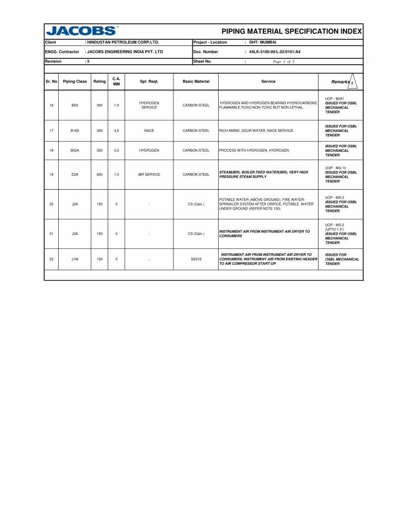
:
RemarksPiping Class
PIPING MATERIAL SPECIFICATION INDEX
Project - Location : DHT- MUMBAIClient : HINDUSTAN PETROLEUM CORP.LTD.
Revision : 5
ServiceSr. No
Sheet No.
Doc. Number : 44LK-5100-00/L.02/0101/A4
Spl. Reqt.RatingC.A.
MMBasic Material
ENGG. Contractor : JACOBS ENGINEERING INDIA PVT. LTD
5
UOP - B2A1
ISSUED FOR OSBL
MECHANICAL
TENDER
ISSUED FOR OSBL
MECHANICAL
TENDER
ISSUED FOR OSBL
MECHANICAL
TENDER
UOP - MS-13
ISSUED FOR OSBL
MECHANICAL
TENDER
UOP - MS-2
ISSUED FOR OSBL
MECHANICAL
TENDER
UOP - MS-2
(UPTO 1.5")
ISSUED FOR OSBL
MECHANICAL
TENDER
ISSUED FOR
OSBL MECHANICAL
TENDER
- SS316
INSTRUMENT AIR FROM INSTRUMENT AIR DRYER TO
CONSUMERS, INSTRUMENT AIR FROM EXISTING HEADER
TO AIR COMPRESSOR START-UP
22 J1M 150 0
NACE CARBON STEEL RICH AMINE, SOUR WATER, NACE SERVICE.
B5A 30016
60019 IBR SERVICE1.5D2A
17 B16A 300 4.5
- CS (Galv.)
POTABLE WATER (ABOVE GROUND), FIRE WATER-
SPRINKLER SYSTEM AFTER ORIFICE, POTABLE WATER
UNDER GROUND (REFER NOTE 130)
HYDROGEN AND HYDROGEN BEARING HYDROCARBONS -
FLAMMABLE,TOXIC/NON-TOXIC BUT NON-LETHAL.
HYDROGEN
SERVICECARBON STEEL
20 J2A 150 0
STEAM(IBR), BOILER FEED WATER(IBR), VERY HIGH
PRESSURE STEAM SUPPLYCARBON STEEL
1.5
- CS (Galv.)INSTRUMENT AIR FROM INSTRUMENT AIR DRYER TO
CONSUMERS21 J3A 150 0
HYDROGEN CARBON STEEL PROCESS WITH HYDROGEN, HYDROGEN18 B52A 300 3.0
Page 2 of 2 .

SPECIAL NOTES
REFER JACOBS STD. 44LK-5100-0350, VF3.
SW NIPPLE WITH VALVE TO SPEC. AS PER 44LK-5100-0354
AS PER P& ID OR 0.75". REFER JACOBS STD. 44LK-5100-0351, V4.
FLANGED, REFER JACOBS STD. 44LK-5100-0353.
AS PER P& ID OR 0.75". REFER JACOBS STD. 44LK-5100-0351, D4.
SW COUPLNG
REFER JACOBS STD. 44LK-5100-0350, DF3.
BUTT WELDED
-29.0
PRESS 16.1720.03
TEMP
PIPE JOINTS 1.5" AND BELOW
1. NDT REQUIREMENT SHALL BE AS PER JACOBS STANDARD 44LK-5100-00/L.02/0103/A4.
NON CORROSIVE / FLAMMABLE / NON FLAMMABLE / NON LETHAL- PROCESS & HYDROCARBONS;
ITEM
CARBON DIOXIDE; WATER - BEYOND A3A; CBD (A/G AND U/G- REFER NOTE 124), BEARING COOLING WATER SUPPLY & RETURN,
SIZE
ALLMAINT. JOINTS FLANGED, TO BE KEPT MINIMUM
A. CODEDESCRIPTION
9.84 8.78 7.7318.28 14.06
204.0
SERVICE
3 . FOR STRAINERS AND SPACER & BLINDS,REFER JACOBS STANDARD DRAWINGS.
20.03
93.0 316.0260.0
CONDENSATE, SUSPECT CONDENSATE TO CONDENSATE POLISHING UNIT, FLUSHING OIL
11.95
ON LINES >= 2"
0.75"
TEMP. CONN. 1.5"
PRESS. CONN.
VENTS ON LINES <=1.5"
ON LINES >= 2"
ON LINES <=1.5"DRAINS
2" AND ABOVE
: 2
TEMPERATURE ( Deg. C ) AND PRESSURE ( Kg/Sq. cm g ) RATINGS
38.0
REVISION
371.0149.0 343.0
Project - Location
PIPING MATERIAL SPECIFICATION
ClientRATING : 150 #
BASIC MATERIAL : CARBON STEEL
PIPE CLASS: HINDUSTAN PETROLEUM CORP. LTD.
CORR. ALLOWANCE
PMC
Document No.: 1.5 MM
SPECIAL REQUIREMENT : - : JACOBS ENGINEERING. INDIA PVT. LTD.
: 44LK-5100-00/L.02/0101/A4A1A
Page 1 of 4
: DHT MUMBAI
LUBE OIL BEFORE FILTER; AMMONIA; STEAM & CONDENSATE (NON IBR); UTILITIES - PLANT AIR; NITROGEN;
4 . FOR RESTRICTION ON THE USE OF BALL, PLUG & BUTTERFLY VALVES, REFER GENERAL NOTES.
2 . USE PIPE OF CLASS 22 INSTEAD OF CLASS 12 IF PIPE THICKNESS EXCEEDS 19.05 MM.
9 . ALL UNDERGROUND PIPING SHALL BE PROVIDED WITH CORROSION RESISTANCE PROTECTION AS PER APPLICABLE SPECIFICATION.
DEPTH OF COVER FOR UNDER GROUND PIPING FOR ADDITIONAL / MISSING SIZES.
UTILITY WATER, RAW WATER TO DM WATER PLANT FEED, POLISHED CONDENSATE POLISHING UNIT TO BOILER, PURE
NOTES
7 . ASBESTOS FREE GASKETS AND STEM PACKING SHALL BE USED FOR VALVES.
8 . THICKNESS TO BE CALCULATED BY THE DETAIL ENGINEERING CONTRACTOR BASED ON SOIL PROPERTIES AND
5 . GATE VALVES OF SIZE 26" AND ABOVE SHALL BE IN ACCORDANCE WITH BS-1414 AND FLANGE ENDS SHALL BE
IN ACCORDENCE WITH B16.47B
6 . NON DESTRUCTIVE EXAMINATION REQUIREMENT FOR CARBON STEEL PIPING CLASSES SHALL BE STRINGENT OF
JACOBS STANDARD 44LK-5100-00/L.02/0103/A4 & LICENSOR'S REQUIREMENT.
2

T 48
T R 46
T R R 44
T R R R 42
T R R R R 40
T R R R R R 38
T R R R R R R 36
T R R R R R R R 34
T R R R R R R R R 32
T R R R R R R R R R 30
T R R R R R R R R R R 28
T R R R R R R R R R R R 26
T R R R R R R R R R R R R 24
22
T R R R R R R R R R R R R R 20
T R R R R R R R R R R R R R R 18
T R R R R R R R R R R R R R R R 16
T R R R R R R R R R R R R R R R R 14
T R R R R R R R R R R R R R R R R R 12
T R R R R R R R R R R R R R R R R R R 10
T P R R R R R R R R R R R R R R R R R R 8
T P P P R R R R R R R R R R R R R R R R R 6
5
T P P P P R R R R R R R R R R R R R R R R R 4
3½
T P P P P P R R R R R R R R R R R R R R R R R 3
2½
T P P P P P R R R R R R R R R R R R R R R R R R 2
T T H H H H H H H H H H H H H H H H H H H H H H H 1½
1¼
T T H H H H H H H H H H H H H H H H H H H H H H H H 1
T T T H H H H H H H H H H H H H H H H H H H H H H H H ¾
T T T T H H H H H H H H H H H H H H H H H H H H H H H H ½
¼
¼ ½ ¾ 1 1¼
1½ 2 2½ 3 3½ 4 5 6 8 10
12
14
16
18
20
22
24
26
28
30
32
34
36
38
40
42
44
46
48
CODE DESCRIPTION
F SADDLE FUSED JT T TEES
H H. COUPLING W WELDOLETS
P PIPE TO PIPE I INSTRUMENT TEE
R REINFORCED X REFER NOTES
S SOCKOLETS L SWEEPOLET
J THREADOLET
A1A: JACOBS ENGINEERING. INDIA PVT. LTD.
PIPING MATERIAL SPECIFICATION
Client
SPECIAL REQUIREMENT PMC
RATING : 150 # : HINDUSTAN PETROLEUM CORP. LTD. PIPE CLASS
BRANCH CONNECTIONS
Project - Location: DHT MUMBAI
: 44LK-5100-00/L.02/0101/A4Document No.
RUN PIPE NB
BR
AN
CH
PIP
E N
B
BASIC MATERIAL : CARBON STEEL
REVISION : 2
: -
: 1.5 MMCORR. ALLOWANCE
Page 2 of 4

Note
No
2
2
BE, E.FS.W
ASTM A 234 GR.WPB-W
BE, E.FS.W
BW, 1.5D
SW, 3000
SW, 3000
ASTM A 234 GR.WPB
PIP PIPE 28.000 36.000 STD B-36.10 ASTM A 672 GR.B60 CL.12
B-16.9
B-16.11 ASTM A 105
ASTM A 105
M B-16.9
B-16.11
M, M
REDC
REDC REDUC.CONC 02.000
TEQ
ELB45 ELBOW.45 0.500 01.500
ELB90 ELBOW.90 02.000 14.000
0.500 01.500 B-16.11
ELB45 ELBOW.45 16.000 48.000 ASTM A 234 GR.WPB-W BW, 1.5D
ELB90 ELBOW.90
PIP PIPE 02.000 06.000
8.0 B-36.10 ASTM A 672 GR.B60 CL.12
SPECIAL REQUIREMENT
PIP 0.500PIPE
: - PMC
Input
Id.
Document No.CORR. ALLOWANCE : 1.5 MM
REVISION : 2
Lower
Size
(Inch)
Upper
Size
(Inch)
ASTM A 672 GR.B60 CL.12 BE, E.FS.W6.0 B-36.10
S20
S10
STD
Project - Location
Pipe Group
: JACOBS ENGINEERING. INDIA PVT. LTD.
BASIC MATERIAL
ASTM A 106 GR.B PE, SEAMLESS01.500
Item
Type
XS
DescriptionCommodity
CodeMaterialDmn. STD
Sch/
Thk
PIP PIPE 08.000 12.000
B-36.10 ASTM A 106 GR.B BE, SEAMLESS
B-36.10
B-36.10 ASTM A 106 GR.B BE, SEAMLESS
ASTM A 106 GR.B BE, SEAMLESSB-36.10
0.750
PIPE 14.000 14.000
PIPE 22.000 26.000
16.000 20.000
M B-36.10 ASTM A 106 GR.B PBE, SEAMLESS
PIP
NIP NIPPLE 01.000
NIP NIPPLE 0.500
PIP
PIP PIPE
01.500 M B-36.10 ASTM A 106 GR.B PBE, SEAMLESS
M B-16.5 ASTM A 105FLG FLNG. WN 0.500 24.000 150, RF / 125AARH
FLG FLNG. WN 26.000 48.000 M B-16.47-B ASTM A 105 150, RF / 125AARH
FLB FLNG.BLIND 0.500 24.000 B-16.5 ASTM A 105 150, RF / 125AARH
FLB FLNG.BLIND 26.000 48.000 B-16.47-B ASTM A 105 150, RF / 125AARH
ASME
B-16.48ASTM A 105 150, FF / 125AARHFEF FLNG.FIG.8 0.500 08.000
FEF SPCR&BLND 10.000 24.000ASME
B-16.48ASTM A 105 150, FF / 125AARH
26.000 48.000 MNF 'STD ASTM A 516 GR.70 150, FF / 125AARH
M
T.EQUAL 0.500 01.500
TEQ T.EQUAL 02.000 14.000
BW
M B-16.9 ASTM A 234 GR.WPB BW
M B-16.9 ASTM A 234 GR.WPB-WTEQ T.EQUAL 16.000 48.000
02.000 14.000
TRED T.RED 0.500 01.500
TRED T.RED
Flange Group
ELB90 ELBOW.90 16.000 48.000 M
FEF SPCR&BLND
B-16.9
BWREDE REDUC.ECC 02.000 14.000 B-16.9 ASTM A 234 GR.WPB
BW
SWGC SWAGE.CONC 0.500 03.000
03.000
M, M BS-3799 ASTM A 105 PBE
BS-3799 ASTM A 105 PBE
BW
BW
BW
BW
SW,3000
ASTM A 234 GR.WPB-W BW, 1.5D
ASTM A 105 SW, 3000
BW, 1.5D
ASTM A 234 GR.WPB-W
B-16.11 ASTM A 105
M, M
REDE
TRED T.RED 16.000 48.000 M, M
SWGE SWAGE.ECC 0.500
Fitting Group
ASTM A 234 GR.WPB-WM, M
M, M
14.000
M, M B-16.9 ASTM A 234 GR.WPB
ASTM A 234 GR.WPB
B-16.9
M, M
PIPING MATERIAL SPECIFICATION
: DHT MUMBAI
Client : HINDUSTAN PETROLEUM CORP. LTD.RATING
: CARBON STEEL
: 150 #
A1A: 44LK-5100-00/L.02/0101/A4
M: TO MATCH PIPE SCHEDULE.
PIPE CLASS
REDUC.ECC 16.000 48.000 B-16.9
REDUC.CONC 16.000 48.000 B-16.9
B-16.9
ELB45 ELBOW.45 02.000 14.000 M B-16.9 ASTM A 234 GR.WPB
PIP PIPE 40.000 48.000 XS B-36.10 ASTM A 672 GR.B60 CL.12 BE, E.FS.W 2
2
Page 3 of 4

Note
No
SPECIAL REQUIREMENT : - PMC
Input
Id.
Document No.CORR. ALLOWANCE : 1.5 MM
REVISION : 2
Lower
Size
(Inch)
Upper
Size
(Inch)
Project - Location
: JACOBS ENGINEERING. INDIA PVT. LTD.
BASIC MATERIAL
Item
TypeDescription
Commodity
CodeMaterialDmn. STD
Sch/
Thk
PIPING MATERIAL SPECIFICATION
: DHT MUMBAI
Client : HINDUSTAN PETROLEUM CORP. LTD.RATING
: CARBON STEEL
: 150 #
A1A: 44LK-5100-00/L.02/0101/A4
PIPE CLASS
5
PLV VLV.PLUG 0.500 24.000 BS-5353BODY-ASTM A105/ A 216 GR.WCB,
TRIM-PLUG HARDENED
FLGD, 150, B-16.5,
RF/125AARH, Tag No.
55301
M: TO MATCH PIPE SCHEDULE.
CAP CAP 02.000 48.000
GAS GASKET 0.500 24.000B-16.20,
ANSI B16.5SP.WND SS 316+ GRAFIL SPIRAL, 150
GAS GASKET 26.000 48.000B-16.20-
ANSI B 16.47 BSP.WND SS 316+ GRAFIL + I RING SPIRAL, 150
MNF' STDB : A 516 GR.70,
INT : SS304
CONE TYPE, 150,
FF / 125AARHTSR STRNR.TEMP 01.500 24.000
PSR STRNR.PERM 0.500 01.500 MNF' STD B : A 105; INT: SS 304 SW, Y-TYPE, 800
PSR STRNR.PERM 02.000 14.000 M MNF' STDB : A 234 GR.WPB;
INT : SS 304BW, T- TYPE
CPLF CPLNG.FULL 0.500 01.500
01.500
B-16.11 ASTM A 105 SW, 3000
Valves Group
B-16.11 ASTM A 105 SW, 3000CPLH CPLNG.HALF 0.500
API-602 BODY- ASTM A 105, TRIM- 8SW, 800, 3000,
B-16.11, Tag No. 51001GAV VLV. GATE 0.500 01.500
GAV VLV. GATE 02.000 42.000 API-600BODY- ASTM A 216 GR.WCB,
TRIM- 8
FLGD, 150, B-16.5,
RF/125AARH, Tag No.
51301
BS-5352 BODY- ASTM A 105, TRIM- 8SW, 800, 3000,
B-16.11, Tag No. 52001
16.000
GLV VLV. GLOBE 0.500 01.500
GLV VLV. GLOBE 02.000
BS-1868
BS-1873BODY- ASTM A 216 GR.WCB,
TRIM-8
FLGD, 150, B-16.5,
RF/125AARH, Tag No.
52301
BS-5352 BODY- ASTM A 105, TRIM-8
CHV VLV.CHECK 02.000 24.000
24.000
BLV VLV.BALL 0.500 16.000 BS-5351BODY - ASTM A105/ A 216 GR.WCB,
TRIM- BODY SEAT-RPTFE
FLGD, 150, B-16.5,
RF/125AARH, Tag No.
54301
WAFL, 150, B-16.5,
WAF/125AARH, Tag No.
56301
BS-5155BODY- ASTM A 105/ A 216GR.WCB,
TRIM- 13%CR.STEEL
FLGD, 150, B-16.47 B,
RF/125AARH, Tag No.
56315
Bolt Group
BFV VLV.BTRFLY 26.000 48.000
API 609 /
BS-5155
BODY- ASTM A 105/ A 216GR.WCB,
TRIM- 13%CR.STEEL
PLV/1 VLV.PLUG 0.500
BFV VLV.BTRFLY 03.000
B : A 105; T: 13% CR:
S : SS 304
FLGD, THRMDNMC, 150,
RF / 125 AARH
0.500 48.000BOLT : A 193 GR.B7,
NUT : A 194 GR.2H
Trap/Strainer Group
CHV VLV.CHECK 0.500 01.500
BODY- ASTM A 216 GR.WCB,
TRIM- 8
FLGD, 150, B-16.5,
RF/125AARH, Tag No.
53301
SW, 800, 3000,
B-16.11, Tag No. 53001
B-16.9 ASTM A 234 GR.WPB BW
B-18.2
TRP
BS-5353
TRAP.STEAM 0.500 01.500 MNF' STD
M MNF' STDB : A 234 GR.WPB;
INT : SS 304BW, T- TYPEPSR STRNR.PERM 16.000 24.000
Gasket Group
BOS BOLT. STUD
36.000
Fitting Group
BODY- ASTM A105/ A 216 GR.WCB,
TRIM- PLUG HARDENED
FLGD, 150, B-16.5,
RF/125AARH, Tag No.
55315
M
G3V VLV.PISTON 0.500 01.500 MNF' STDBODY- ASTM A 105/,
TRIM- 13%CR.STEEL
SW, 800, 3000, B 16.11,
Tag No. 64001
G3V VLV.PISTON 02.000 08.000 MNF' STDBODY- ASTM A 216GR.WCB,
TRIM- 13%CR.STEEL
FLGD, 150, B-16.5 ,
RF/125AARH, Tag No.
64301
2
2
2
2
2
2
2
2
2
2
2
2
2
Page 4 of 4

AS PER P& ID OR 0.75". REFER JACOBS STD. 44LK-5100-0351, V1.
FLANGED, REFER JACOBS STD. 44LK-5100-0353.
BUTT WELDED
SPECIAL NOTES
2 . FOR STRAINERS AND SPACER & BLINDS,REFER JACOBS STANDARD DRAWINGS.
3 . FOR RESTRICTION ON THE USE OF BALL, PLUG & BUTTERFLY VALVES, REFER GENERAL NOTES.
PRESS 16.17#### 14.06
REFER JACOBS STD. 44LK-5100-0350, VC1.
SW, SH HVY NIPPLE WITH GATE VALVE TO SPEC. AS PER 44LK-5100-0354
FLANGED, TO BE KEPT MINIMUM
DESCRIPTION
1.5" AND BELOW
2" AND ABOVE
REFER JACOBS STD. 44LK-5100-0350, DF3.
18.28
-29.0
HYDROGEN AND HYDROGEN BEARING HYDROCARBONS (NOTE 62) - FLAMMABLE,TOXIC/NON-TOXIC BUT NON-LETHAL, FUEL GAS
204.0
ITEM A. CODESIZE
4 . FOR HYDROGEN SERVICE,CARBON STEEL PIPING MATERAILS WITH WALL THICKNESS3/8 INCH AND OVER SHALL BE NORMALISED.
SERVICE
20.03
93.0 ####
####
TEMP
ON LINES >= 2"
0.75"
TEMP. CONN. 1.5"
PRESS. CONN.
ON LINES <=1.5"
ON LINES >= 2"
ON LINES <=1.5"DRAINS
VENTS
: 2
TEMPERATURE ( Deg. C ) AND PRESSURE ( Kg/Sq. cm g ) RATINGS
38.0
REVISION
149.0
Project - Location
PIPING MATERIAL SPECIFICATION
ClientRATING : 150 #
BASIC MATERIAL : CARBON STEEL
PIPE CLASS: HINDUSTAN PETROLEUM CORP. LTD.
CORR. ALLOWANCE
PMC
Document No.: 1.5 MM
SPECIAL REQUIREMENT: HYDROGEN SERVICE : JACOBS ENGINEERING. INDIA PVT. LTD.
: 44LK-5100-00/L.02/0101/A4A5A
Page 1 of 4
: DHT MUMBAI
NOTES
7 . ASBESTOS FREE GASKETS AND STEM PACKING SHALL BE USED FOR VALVES.
6 . NON DESTRUCTIVE EXAMINATION REQUIREMENT FOR CARBON STEEL PIPING CLASSES SHALL BE STRINGENT OF
JACOBS STANDARD 44LK-5100-00/L.02/0103/A4 & LICENSOR'S REQUIREMENT.
1. NDT REQUIREMENT SHALL BE AS PER JACOBS STANDARD 44LK-5100-00/L.02/0103/A4.
5 . ANY MEDIUM CONTAINING HYDROGEN GAS WITH A PARTIAL PRESSURE OF 100 PSI & ABOVE SHALL BE CONSIDERED AS HYDROGEN SERVICE.
ALLMAINT. JOINTS
AS PER P& ID OR 0.75". REFER JACOBS STD. 44LK-5100-0351, D4.
SW COUPLNG 3000 LBS.PIPE JOINTS
2

48
44
42
40
36
34
32
30
26
T 24
T R 22
T R R 20
T R R R 18
T R R R R 16
T R R R R R 14
T R R R R R R 12
T R R R R R R R 10
T P R R R R R R R 8
T P P P R R R R R R 6
5
T P P P P R R R R R R 4
3½
T P P P P P R R R R R R 3
2½
T P P P P P R R R R R R R 2
T T H H H H H H H H H H H H 1½
1¼
T T H H H H H H H H H H H H H 1
T T T H H H H H H H H H H H H H ¾
T T T T H H H H H H H H H H H H H ½
¼
¼ ½ ¾ 1 1¼
1½ 2 2½ 3 3½ 4 5 6 8 10
12
14
16
18
20
22
24
26
30
32
34
36
40
42
44
48
CODE DESCRIPTION
F SADDLE FUSED JT T TEES
H H. COUPLING W WELDOLETS
P PIPE TO PIPE I INSTRUMENT TEE
R REINFORCED X Refer Notes
S SOCKOLETS L SWEEPOLET
J
RUN PIPE NB
BR
AN
CH
PIP
E N
B
Page 2 of 4
BRANCH CONNECTIONS
BASIC MATERIAL : CARBON STEEL
REVISION : 2
: HYDROGEN
SERVICE
: 1.5 MMCORR. ALLOWANCE
A5AProject - Location: DHT MUMBAI
: 44LK-5100-00/L.02/0101/A4Document No.
: JACOBS ENGINEERING. INDIA PVT. LTD.
THREADOLET
PIPING MATERIAL SPECIFICATION
Client
SPECIAL REQUIREMENT PMC
RATING : 150 # : HINDUSTAN PETROLEUM CORP. LTD. PIPE CLASS

Note
No
M B-16.9 ASTM A 234 GR.WPB
PIPE CLASS
BW, 1.5D
Fitting Group
Flange Group
FEF SPCR&BLND
REDE B-16.9REDUC.ECC 16.000 24.000
M
M, M
B-16.9
PIPING MATERIAL SPECIFICATION
: DHT MUMBAI
Client : HINDUSTAN PETROLEUM CORP. LTD.RATING
: CARBON STEEL
: 150 #
A5A: 44LK-5100-00/L.02/0101/A4
M, M
REDUC.CONC 16.000 24.000 B-16.9M, M
B-16.9 ASTM A 234 GR.WPB
ASTM A 234 GR.WPB-W
B-16.9 ASTM A 234 GR.WPB
BW
BW
ASTM A 234 GR.WPB BW
CPLH CPLNG.HALF 0.500 1.500 B-16.11 ASTM A 105 SW, 3000
B-16.11 ASTM A 105 SW, 3000CPLF CPLNG.FULL 0.500 1.500
CAP CAP 2.000 24.000
SWGE SWAGE.ECC 0.500 3.000
REDE REDUC.ECC
M, M BS-3799 ASTM A 105 PBE
BS-3799 ASTM A 105 PBE
SWGC SWAGE.CONC 0.500 3.000
BW2.000 14.000 M, M
BWASTM A 234 GR.WPB-W
REDC REDUC.CONC 2.000 14.000
TRED T.RED 2.000 14.000
TRED T.RED 0.500 1.500 B-16.11 ASTM A 105 SW, 3000
TEQ T.EQUAL 16.000 24.000 M B-16.9 ASTM A 234 GR.WPB-W BW
M B-16.9 ASTM A 234 GR.WPB BWTEQ T.EQUAL 2.000 14.000
TEQ T.EQUAL 0.500 1.500 B-16.11 ASTM A 105 SW, 3000
10.000 24.000ASME
B-16.48ASTM A 105 150, FF/125AARH
M ASTM A 234 GR.WPB-W
FEF FLNG.FIG.8 0.500 8.000ASME
B-16.48ASTM A 105 150, FF/125AARH
150, RF/125AARH
FLB FLNG.BLIND 0.500 24.000 B-16.5 ASTM A 105 150, RF/125AARH
FLG FLNG. WN 0.500 24.000
M B-36.10 ASTM A 106 GR.B PBE, SEAMLESS
M B-16.5 ASTM A 105
NIP NIPPLE 0.500 1.500
PIPE 22.000 24.000PIP 8.0 B-36.10 ASTM A 672 GR.B60 CL.32 BE, E.FS.W
ASTM A 672 GR.B60 CL.32 BE, E.FS.WB-36.10
S10
PIP PIPE 16.000 20.000
B-36.10 ASTM A 106 GR.B BE, SEAMLESS
B-36.10
DescriptionCommodity
CodeMaterialDmn. STD
Sch/
Thk
B-36.10
S20 B-36.10
Item
Type
STD
XS
6.0
6.000
8.000 12.000
Project - Location
: HYDROGEN
SERVICEPMC
PIP PIPE
Input
Id.
Document No.CORR. ALLOWANCE : 1.5 MM
Pipe Group
: JACOBS ENGINEERING. INDIA PVT. LTD.
BASIC MATERIAL
ASTM A 106 GR.B PE, SEAMLESS
REVISION : 2
Lower
Size
(Inch)
Upper
Size
(Inch)
1.500
SPECIAL REQUIREMENT
PIP PIPE 2.000
PIP 0.500PIPE
ASTM A 106 GR.B BE, SEAMLESS
ASTM A 106 GR.B BE, SEAMLESS
PIP PIPE 14.000 14.000
BW, 1.5D
ELB90 ELBOW.90
B-16.9
ELB45 ELBOW.45 2.000 14.000
ELB45 ELBOW.45 16.000 24.000
0.500 1.500 B-16.11 ASTM A 105 SW, 3000
ELB90 ELBOW.90 2.000 14.000 M B-16.9 ASTM A 234 GR.WPB BW, 1.5D
ELB90 ELBOW.90 16.000 24.000 M B-16.9 ASTM A 234 GR.WPB-W BW, 1.5D
ELB45 ELBOW.45 0.500 1.500 B-16.11 ASTM A 105 SW, 3000
24.000
M, M B-16.9 ASTM A 234 GR.WPB BW
M, M
M: TO MATCH PIPE SCHEDULE.
B-16.9 ASTM A 234 GR.WPB-W BW
M, M
REDC
TRED T.RED 16.000
Page 3 of 4
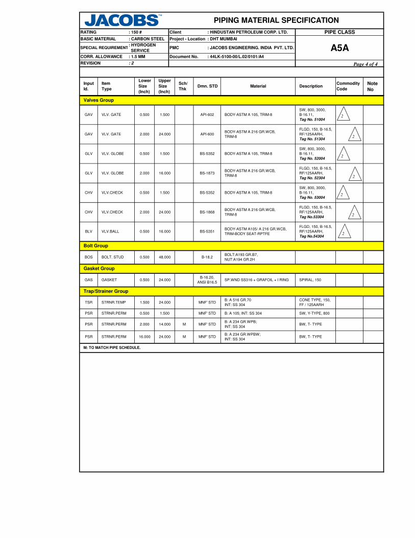
Note
No
PIPE CLASS
PIPING MATERIAL SPECIFICATION
: DHT MUMBAI
Client : HINDUSTAN PETROLEUM CORP. LTD.RATING
: CARBON STEEL
: 150 #
A5A: 44LK-5100-00/L.02/0101/A4
DescriptionCommodity
CodeMaterialDmn. STD
Sch/
Thk
Item
Type
Project - Location
: HYDROGEN
SERVICEPMC
Input
Id.
Document No.CORR. ALLOWANCE : 1.5 MM
: JACOBS ENGINEERING. INDIA PVT. LTD.
BASIC MATERIAL
REVISION : 2
Lower
Size
(Inch)
Upper
Size
(Inch)
SPECIAL REQUIREMENT
M MNF' STDB: A 234 GR.WPBW;
INT: SS 304BW, T- TYPEPSR STRNR.PERM 16.000 24.000
Gasket Group
BOS BOLT. STUD B-18.2
BODY-ASTM A 216 GR.WCB,
TRIM-8
FLGD, 150, B-16.5,
RF/125AARH,
Tag No.53304
SW, 800, 3000,
B-16.11,
Tag No. 52004
SW, 800, 3000,
B-16.11,
Tag No. 53004
FLGD, 150, B-16.5,
RF/125AARH,
Tag No. 52304
GLV VLV. GLOBE
CHV VLV.CHECK 0.500 1.500
BLV
0.500 48.000BOLT:A193 GR.B7,
NUT:A194 GR.2H
Bolt Group
VLV.BALLBODY-ASTM A105/ A 216 GR.WCB,
TRIM-BODY SEAT-RPTFE
FLGD, 150, B-16.5,
RF/125AARH,
Tag No.54304
CHV VLV.CHECK 2.000 24.000 BS-1868
0.500
BS-5352
16.000 BS-5351
BODY-ASTM A 105, TRIM-8
2.000 16.000 BS-1873BODY-ASTM A 216 GR.WCB,
TRIM-8
GLV VLV. GLOBE 0.500 1.500 BS-5352 BODY-ASTM A 105, TRIM-8
API-600BODY-ASTM A 216 GR.WCB,
TRIM-8
FLGD, 150, B-16.5,
RF/125AARH,
Tag No. 51304
GAV VLV. GATE 2.000 24.000
Valves Group
API-602 BODY-ASTM A 105, TRIM-8
SW, 800, 3000,
B-16.11,
Tag No. 51004
GAV VLV. GATE 0.500 1.500
PSR STRNR.PERM 2.000 14.000 M MNF' STDB: A 234 GR.WPB;
INT: SS 304BW, T- TYPE
MNF' STD B: A 105; INT: SS 304 SW, Y-TYPE, 800PSR STRNR.PERM 0.500 1.500
TSR STRNR.TEMP 1.500 24.000 MNF' STDB: A 516 GR.70
INT: SS 304
CONE TYPE, 150,
FF / 125AARH
Trap/Strainer Group
B-16.20,
ANSI B16.5SP.WND SS316 + GRAFOIL + I RING SPIRAL, 150GAS GASKET 0.500 24.000
M: TO MATCH PIPE SCHEDULE.
2
2
2
2
2
2
2
Page 4 of 4
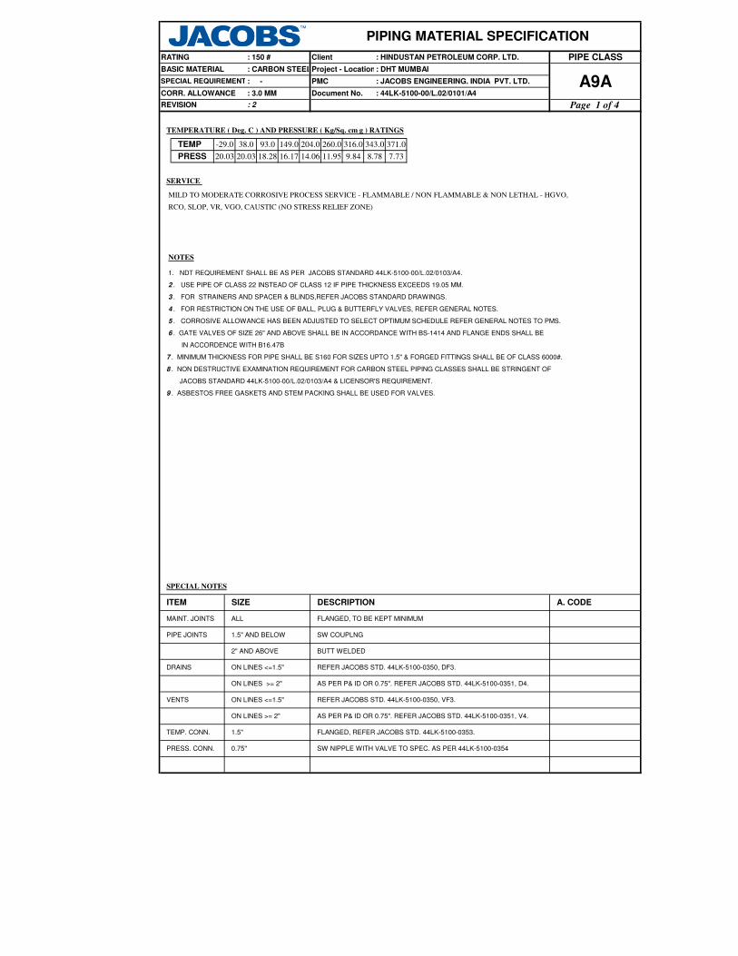
SPECIAL NOTES
REFER JACOBS STD. 44LK-5100-0350, VF3.
SW NIPPLE WITH VALVE TO SPEC. AS PER 44LK-5100-0354
AS PER P& ID OR 0.75". REFER JACOBS STD. 44LK-5100-0351, V4.
FLANGED, REFER JACOBS STD. 44LK-5100-0353.
AS PER P& ID OR 0.75". REFER JACOBS STD. 44LK-5100-0351, D4.
SW COUPLNG
REFER JACOBS STD. 44LK-5100-0350, DF3.
BUTT WELDED
-29.0
PRESS 16.1720.03
TEMP
PIPE JOINTS 1.5" AND BELOW
1. NDT REQUIREMENT SHALL BE AS PER JACOBS STANDARD 44LK-5100-00/L.02/0103/A4.
MILD TO MODERATE CORROSIVE PROCESS SERVICE - FLAMMABLE / NON FLAMMABLE & NON LETHAL - HGVO,
ITEM SIZE
ALLMAINT. JOINTS FLANGED, TO BE KEPT MINIMUM
A. CODEDESCRIPTION
9.84 8.78 7.7318.28 14.06
204.0
SERVICE
3 . FOR STRAINERS AND SPACER & BLINDS,REFER JACOBS STANDARD DRAWINGS.
20.03
93.0 316.0260.0
11.95
ON LINES >= 2"
0.75"
TEMP. CONN. 1.5"
PRESS. CONN.
VENTS ON LINES <=1.5"
ON LINES >= 2"
ON LINES <=1.5"DRAINS
2" AND ABOVE
: 2
TEMPERATURE ( Deg. C ) AND PRESSURE ( Kg/Sq. cm g ) RATINGS
38.0
REVISION
371.0149.0 343.0
Project - Location
PIPING MATERIAL SPECIFICATION
ClientRATING : 150 #
BASIC MATERIAL : CARBON STEEL
PIPE CLASS: HINDUSTAN PETROLEUM CORP. LTD.
CORR. ALLOWANCE
PMC
Document No.: 3.0 MM
SPECIAL REQUIREMENT : - : JACOBS ENGINEERING. INDIA PVT. LTD.
: 44LK-5100-00/L.02/0101/A4A9A
Page 1 of 4
: DHT MUMBAI
RCO, SLOP, VR, VGO, CAUSTIC (NO STRESS RELIEF ZONE)
4 . FOR RESTRICTION ON THE USE OF BALL, PLUG & BUTTERFLY VALVES, REFER GENERAL NOTES.
2 . USE PIPE OF CLASS 22 INSTEAD OF CLASS 12 IF PIPE THICKNESS EXCEEDS 19.05 MM.
5 . CORROSIVE ALLOWANCE HAS BEEN ADJUSTED TO SELECT OPTIMUM SCHEDULE REFER GENERAL NOTES TO PMS.
NOTES
9 . ASBESTOS FREE GASKETS AND STEM PACKING SHALL BE USED FOR VALVES.
7 . MINIMUM THICKNESS FOR PIPE SHALL BE S160 FOR SIZES UPTO 1.5" & FORGED FITTINGS SHALL BE OF CLASS 6000#.
6 . GATE VALVES OF SIZE 26" AND ABOVE SHALL BE IN ACCORDANCE WITH BS-1414 AND FLANGE ENDS SHALL BE
IN ACCORDENCE WITH B16.47B
8 . NON DESTRUCTIVE EXAMINATION REQUIREMENT FOR CARBON STEEL PIPING CLASSES SHALL BE STRINGENT OF
JACOBS STANDARD 44LK-5100-00/L.02/0103/A4 & LICENSOR'S REQUIREMENT.

72
64
60
56
52
48
46
44
42
40
38
T 36
R 34
T R 32
T R R 30
T R R R 28
T R R R R 26
T R R R R R 24
22
T R R R R R R 20
T R R R R R R R 18
T R R R R R R R R 16
T R R R R R R R R R 14
T R R R R R R R R R R 12
T R R R R R R R R R R R 10
T R R R R R R R R R R R R 8
T R R R R R R R R R R R R R 6
5
T P R R R R R R R R R R R R R 4
3½
T P P R R R R R R R R R R R R R 3
2½
T P P P R R R R R R R R R R R R R 2
T T H H H H H H H H H H H H H H H H 1½
1¼
T T H H H H H H H H H H H H H H H H H 1
T T T H H H H H H H H H H H H H H H H H ¾
T T T T H H H H H H H H H H H H H H H H H ½
¼
¼ ½ ¾ 1 1¼
1½ 2 2½ 3 3½ 4 5 6 8 10
12
14
16
18
20
22
24
26
28
30
32
34
36
38
40
42
44
46
48
52
56
60
64
72
Page 2 of 4
: DHT MUMBAI
: JACOBS ENGINEERING. INDIA PVT. LTD.
PIPE CLASS
A9A
: HINDUSTAN PETROLEUM CORP. LTD.
Project - Location
: 44LK-5100-00/L.02/0101/A4
PMC
Document No.
REVISION : 2
ClientRATING : 150 #
PIPING MATERIAL SPECIFICATION
BR
AN
CH
PIP
E N
B
H
BASIC MATERIAL : CARBON STEEL
SPECIAL REQUIREMENT
CORR. ALLOWANCE : 3.0 MM
: -
R REINFORCED X
P
SWEEPOLET
THREADOLET
Refer Notes
T
IPIPE TO PIPE
WELDOLETSH. COUPLING W
INSTRUMENT TEE
J
S SOCKOLETS L
TEESSADDLE FUSED JTF
CODE
RUN PIPE NB
DESCRIPTION
BRANCH CONNECTIONS

Note
No
7
2
7
7
7
7
SWGE SWAGE.ECC 0.500 03.000 M, M
PIPING MATERIAL SPECIFICATION
BS-3799 ASTM A 105
ClientRATING : 150 #
PBE
M, M BS-3799 ASTM A 105 PBESWGC SWAGE.CONC 0.500 03.000
REDE REDUC.ECC 16.000 36.000 M, M B-16.9 ASTM A 234 GR.WPB- W BW
REDE REDUC.ECC 02.000 14.000 B-16.9 ASTM A 234 GR.WPB BW
BW
M, M B-16.9
REDC REDUC.CONC
REDC REDUC.CONC 02.000 14.000
B-16.9
BW
ASTM A 234 GR.WPB- W
ASTM A 234 GR.WPB
TRED T.RED 16.000 36.000 M, M B-16.9 ASTM A 234 GR.WPB-W BW
M, M B-16.9 ASTM A 234 GR.WPB BW
B-16.11 ASTM A 105 SW, 6000TRED 01.500
TRED T.RED 02.000 14.000
ASTM A 234 GR.WPB-W BW
M14.000
TEQ T.EQUAL 16.000 36.000 M B-16.9
B-16.9 ASTM A 234 GR.WPB BW
BW, 1.5D
TEQ T.EQUAL 0.500 01.500 B-16.11 ASTM A 105 SW, 6000
36.000 M B-16.9 ASTM A 234 GR.WPB-W
B-16.9 ASTM A 234 GR.WPB BW, 1.5D
MNF'STD ASTM A 516 GR.70 150, FF/125AARHFEF SPCR&BLND 26.000 36.000
ASME
B-16.48ASTM A 105 150, FF/125AARHFEF SPCR&BLND 10.000 24.000
ASME
B-16.48ASTM A 105 150, FF/125AARHFEF FLNG.FIG.8 0.500 08.000
B-16.47-B ASTM A 105 150, RF/125AARHFLB FLNG.BLIND 26.000 36.000
FLB FLNG.BLIND 0.500 24.000 B-16.5 ASTM A 105 150, RF/125AARH
24.000
FLG FLNG. WN 26.000 36.000 M B-16.47-B ASTM A 105 150, RF/125AARH
B-16.5 ASTM A 105 150, RF/125AARH
M B-36.10 ASTM A 106 GR.B PBE, SEAMLESS
Flange Group
FLG 0.500
NIP NIPPLE 01.500
BE, E.FS.WSTD B-36.10ASTM A 672
GR.B60 CL.12
0.500
ELB90 ELBOW. 90 0.500
8.0PIP PIPE 16.000 24.000
MFLNG. WN
14.000
12.000
Fitting Group
PIP PIPE
Pipe Group
ASTM A 106 GR.BPIPE
PIP PIPE 02.000 B-36.1002.000
: CARBON STEELBASIC MATERIAL
DescriptionCommodity
CodeMaterial
Project - Location
SPECIAL REQUIREMENT : - PMC
Input
Id.
PIP PIPE
Item
Type
XS
S160
Lower
Size
(Inch)
Upper
Size
(Inch)
PIP 0.500 01.500
CORR. ALLOWANCE : 3.0 MM
Dmn. STD
REVISION : 2
Document No.
Sch/
Thk
ASTM A 106 GR.B BE, SEAMLESS
PE, SEAMLESS
STD B-36.10
B-36.10
03.000 06.000 ASTM A 106 GR.B BE, SEAMLESS
ASTM A 106 GR.B BE, SEAMLESS
ASTM A 106 GR.B BE, SEAMLESS
ASTM A 672
GR.B60 CL.12
B-36.10
PIP PIPE 26.000 36.000
S2008.000
PIP PIPE 14.000 S10 B-36.10
BE, E.FS.WB-36.10
01.500 SW, 6000ASTM A 105B-16.11
ELB90 ELBOW. 90 02.000 14.000 M B-16.9 ASTM A 234 GR.WPB BW, 1.5D
M B-16.9 ASTM A 234 GR.WPB-W BW, 1.5DELB90 ELBOW. 90 16.000 36.000
SW, 600001.500
14.000 M
36.000
M, M
M, M
ELBOW.45 02.000
ELB45 ELBOW.45
ELB45
M: TO MATCH PIPE SCHEDULE
ELB45 ELBOW.45 0.500
16.000
16.000
TEQ T.EQUAL 02.000
T.RED 0.500
B-16.11
A9A
: HINDUSTAN PETROLEUM CORP. LTD.
: DHT MUMBAI
: JACOBS ENGINEERING. INDIA PVT.LTD.
: 44LK-5100-00/L.02/0101/A4
PIPE CLASS
ASTM A 105
2
2
2
2
2
2
Page 3 of 4

Note
No
PIPING MATERIAL SPECIFICATION
ClientRATING : 150 #
: CARBON STEELBASIC MATERIAL
DescriptionCommodity
CodeMaterial
Project - Location
SPECIAL REQUIREMENT : - PMC
Input
Id.
Item
Type
Lower
Size
(Inch)
Upper
Size
(Inch)
CORR. ALLOWANCE : 3.0 MM
Dmn. STD
REVISION : 2
Document No.
Sch/
Thk
A9A
: HINDUSTAN PETROLEUM CORP. LTD.
: DHT MUMBAI
: JACOBS ENGINEERING. INDIA PVT.LTD.
: 44LK-5100-00/L.02/0101/A4
PIPE CLASS
7
7
6
0.500
BLV VLV.BALL 0.500 16.000
BS-5352
BOLT: A 193 GR.B7,
NUT: A 194 GR.2H
24.000
Bolt Group
B-18.2
PLV VLV.PLUG 0.500
36.000
M: TO MATCH PIPE SCHEDULE
BS-5353
BODY-ASTM A105 /
A 216 GR.WCB,
TRIM-PLUG HARDENED
FLGD, 150, B-16.5,
RF/125AARH, Tag No. 55301
Gasket Group
BOS BOLT. STUD
FLGD, 150, B-16.5,
RF/125AARH, Tag No. 54301
BS-1868BODY-ASTM A 216 GR.WCB,
TRIM- SS304, STELLITED
FLGD, 150, B-16.5,
RF/125AARH, Tag No. 53301
BS-5351
BODY- ASTM A 105/
A 216 GR.WCB,
TRIM-BODY SEAT-RPTFE
CHV VLV.CHECK 02.000 24.000
CHV VLV.CHECK 0.500 01.500 BS-5352BODY-ASTM A 105,
TRIM- SS304, STELLITED
SW, 800, 3000, B-16.11,
Tag No. 53001
BS-1873BODY-ASTM A 216 GR.WCB,
TRIM- SS304, STELLITED
FLGD, 150, B-16.5,
RF/125AARH, Tag No. 52301
01.500
GLV VLV. GLOBE 02.000 16.000
GLV VLV. GLOBE
API-602
API-600BODY-ASTM A 216 GR.WCB,
TRIM- SS304, STELLITED
FLGD, 150, B-16.5,
RF/125AARH, Tag No. 51301
BODY-ASTM A 105,
TRIM- SS304, STELLITED
GAV VLV. GATE 0.500 01.500
Valves Group
BODY-ASTM A 105,
TRIM- SS304, STELLITED
SW, 800, 3000,
B-16.11, Tag No. 51001
B-16.11 ASTM A 105 SW, 6000CPLH CPLNG.HALF 0.500 01.500
CPLF CPLNG.FULL 0.500 01.500 B-16.11 ASTM A 105 SW, 6000
M MNF'STDB:A 234 GR.WPB-W;
INT: SS 304BW, T- TYPEPSR STRNR.PERM 16.000 24.000
PSR STRNR.PERM 02.000 14.000 M MNF'STDB: A 234 GR.WPB;
INT: SS304BW, T- TYPE
MNF' STDB: A 105;
INT: SS 304SW, Y-TYPE, 800PSR STRNR.PERM 0.500 01.500
Trap/Strainer Group
TSR STRNR.TEMP 01.500 24.000 MNF' STDB: A 516 GR.70;
INT: SS 304
CONE TYPE, 150,
FF/125AARH
GAS GASKET 26.000 36.000
B-16.20-
ANSI
B 16.47 B
SP.WND SS316 + GRAFOIL +
I RINGSPIRAL, 150
B-16.20,
ANSI B16.5SP.WND SS316 + GRAFOIL SPIRAL, 150GAS GASKET 0.500 24.000
M B-16.9 ASTM A 234 GR.WPB BWCAP CAP 02.000 36.000
SW, 800, 3000,
B-16.11, Tag No. 520010.500
42.000GAV VLV. GATE 02.000
Fitting Group
2
2
2
2
2
2
2
2
2
2
Page 4 of 4

Project - Location
19.57 16.12
1 NDT REQUIREMENT SHALL BE AS PER JOB SPECIFICATION 44LK-5100-00/L.02/0103/A4.
: DHT MUMBAI
A10A: JACOBS ENGINEERING. INDIA PVT. LTD.
: 44LK-5100-00/L.02/0101/A4
PIPING MATERIAL SPECIFICATION
ClientRATING : HINDUSTAN PETROLEUM CORP. LTD. PIPE CLASS: 150 #
A. CODEDESCRIPTION
FLANGED, TO BE KEPT MINIMUM
SW COUPLING
REFER JACOBS STD. 44LK-5100-0350, DF3.
Page 1 of 5
BUTT WELDED
2 FOR RESTRICTION ON USE OF BALL, PLUG & BUTTERFLY VALVES, REFER GENERAL NOTES TO PMS.
ON LINES ≤ 1.5"
2" AND ABOVE
AS PER P& ID OR 0.75". REFER JACOBS STD. 44LK-5100-0351, V4.
AS PER P& ID OR 0.75". REFER JACOBS STD. 44LK-5100-0351, D4.
PMC
Document No.
FLANGED, REFER JACOBS STD. 44LK-5100-0353.
SW NIPPLE WITH VALVE TO SPEC. AS PER 44LK-5100-0354
REFER JACOBS STD. 44LK-5100-0350, VF3.
ALL
18.04
3 GATE VALVES OF SIZE 26" AND ABOVE SHALL BE IN ACCORDANCE WITH BS-1414 AND FLANGE ENDS SHALL BE IN ACCORDANCE
NOTES
WITH ASME B 16.47 SERIES B.
19.98
SPECIAL NOTES
: CARBON STEEL
: NON IBRSPECIAL REQUIREMENT
38 10050
PRESS
BASIC MATERIAL
14.07 12.34
-29
ITEM
ON LINES ≥ 2"
0.75"
TEMP. CONN. 1.5"
PRESS. CONN.
SIZE
DRAINS
PIPE JOINTS 1.5" AND BELOW
19.98
MAINT. JOINTS
HC FLARE
REVISION
VENTS ON LINES ≤ 1.5"
ON LINES ≥ 2"
TEMPERATURE ( Deg. C ) AND PRESSURE ( Kg/Sq. cm g ) RATINGS
SERVICE
CORR. ALLOWANCE : 1.5 MM
250200150TEMP
: 2

T 48
T R 44
T R R 42
T R R R 40
T R R R R 36
34
T R R R R R 32
T R R R R R R 30
T R R R R R R R 26
T R R R R R R R R 24
22
T R R R R R R R R R 20
T R R R R R R R R R R 18
T R R R R R R R R R R R 16
T R R R R R R R R R R R R 14
T R R R R R R R R R R R R R 12
T P R R R R R R R R R R R R R 10
T P P P R R R R R R R R R R R R 8
T P P P P R R R R R R R R R R R R 6
5
T P P P P P R R R R R R R R R R R R 4
3½
T P P P P P P R R R R R R R R R R R R 3
2½
T P P P P P P P P R R R R R R R R R R R 2
T T H H H H H H H H H H H H H H H H H H H 1½
1¼
T T H H H H H H H H H H H H H H H H H H H H 1
T T T H H H H H H H H H H H H H H H H H H H H ¾
T T T T H H H H H H H H H H H H H H H H H H H H ½
¼
¼ ½ ¾ 1 1¼
1½ 2 2½ 3 3½ 4 5 6 8 10
12
14
16
18
20
22
24
26
30
32
34
36
40
42
44
48
CODE DESCRIPTION
F SADDLE FUSED JT T TEES
H H. COUPLING W WELDOLETS
P PIPE TO PIPE I INSTRUMENT TEE
R REINFORCED X REFER NOTES
S SOCKOLETS L SWEEPOLET
J THREADOLET
RUN PIPE NB
BR
AN
CH
PIP
E N
B
Page 2 of 5
BASIC MATERIAL : CARBON STEEL
REVISION : 2
: NON IBR
: 1.5 MMCORR. ALLOWANCE
BRANCH CONNECTIONS
Project - Location : DHT MUMBAI
: 44LK-5100-00/L.02/0101/A4Document No.
: JACOBS ENGINEERING. INDIA PVT. LTD.
PIPING MATERIAL SPECIFICATION
Client
SPECIAL REQUIREMENT PMC
RATING : 150 # : HINDUSTAN PETROLEUM CORP. LTD. PIPE CLASS
A10A
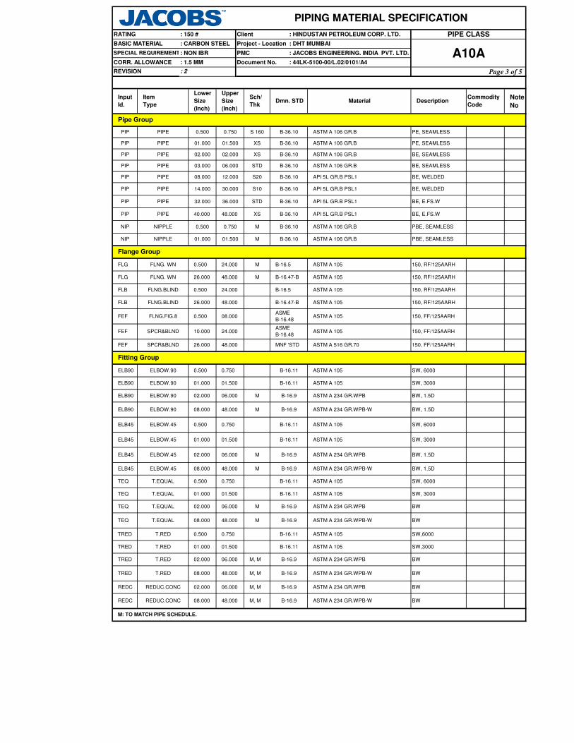
Note
No
SW, 3000ELB45 ELBOW.45 01.000 01.500 B-16.11 ASTM A 105
PIPE CLASS
Fitting Group
REDUC.CONC 08.000 48.000
PIPING MATERIAL SPECIFICATION
: DHT MUMBAI
Client : HINDUSTAN PETROLEUM CORP. LTD.RATING
: CARBON STEEL
: 150 #
A10A: 44LK-5100-00/L.02/0101/A4
B-16.9 ASTM A 234 GR.WPB-WM, M
M: TO MATCH PIPE SCHEDULE.
BW
BW
TRED T.RED 08.000 48.000 M, M B-16.9 ASTM A 234 GR.WPB-W BW
TEQ T.EQUAL 08.000 48.000
SPCR&BLND
B-16.9 ASTM A 234 GR.WPB-W BW, 1.5D
M B-16.9 ASTM A 234 GR.WPB-W BW
02.000 06.000
Flange Group
ELB90 ELBOW.90 08.000 48.000 M
FEF
B-16.9 ASTM A 234 GR.WPB
TRED T.RED 01.000 01.500
06.000 M, M
REDC REDUC.CONC
TRED T.RED 0.500 0.750 B-16.11 ASTM A 105 SW,6000
TEQ T.EQUAL 02.000 06.000 M B-16.9 ASTM A 234 GR.WPB BW
B-16.11 ASTM A 105 SW, 3000TEQ T.EQUAL 01.000 01.500
TEQ T.EQUAL 0.500 0.750 B-16.11 ASTM A 105 SW, 6000
26.000 48.000 MNF 'STD ASTM A 516 GR.70 150, FF/125AARH
M B-16.9
FEF SPCR&BLND 10.000 24.000ASME
B-16.48ASTM A 105 150, FF/125AARH
ASME
B-16.48ASTM A 105 150, FF/125AARHFEF FLNG.FIG.8 0.500 08.000
FLB FLNG.BLIND 26.000 48.000 B-16.47-B ASTM A 105 150, RF/125AARH
150, RF/125AARH
FLB FLNG.BLIND 0.500 24.000 B-16.5 ASTM A 105 150, RF/125AARH
48.000 M B-16.47-B ASTM A 105
FLG FLNG. WN 0.500 24.000 150, RF/125AARH
FLG FLNG. WN 26.000
01.500 M B-36.10 ASTM A 106 GR.B PBE, SEAMLESS
M B-16.5 ASTM A 105
PIP
NIP NIPPLE 01.000
NIP NIPPLE 0.500
PIP
M B-36.10 ASTM A 106 GR.B PBE, SEAMLESS0.750
PIPE 14.000 30.000
PIPE 32.000 36.000
S10 B-36.10 API 5L GR.B PSL1 BE, WELDED
API 5L GR.B PSL1 BE, WELDEDB-36.10
STD
PIP PIPE 08.000 12.000
B-36.10 ASTM A 106 GR.B BE, SEAMLESS
B-36.10
DescriptionCommodity
CodeMaterialDmn. STD
Sch/
Thk
B-36.10
XS B-36.10
Item
Type
XS
S 160
S20
01.500
02.000 02.000
Project - Location
: NON IBR PMC
PIP PIPE
Input
Id.
Document No.CORR. ALLOWANCE : 1.5 MM
Pipe Group
: JACOBS ENGINEERING. INDIA PVT. LTD.
BASIC MATERIAL
ASTM A 106 GR.B PE, SEAMLESS
REVISION : 2
Lower
Size
(Inch)
Upper
Size
(Inch)
0.750
SPECIAL REQUIREMENT
PIP PIPE 01.000
PIP 0.500PIPE
ASTM A 106 GR.B BE, SEAMLESS
ASTM A 106 GR.B PE, SEAMLESS
PIP PIPE 03.000 06.000
ELB45 ELBOW.45 02.000 06.000 ASTM A 234 GR.WPB BW, 1.5D
ELB90 ELBOW.90 0.500 0.750 B-16.11 ASTM A 105 SW, 6000
ELB90 ELBOW.90 01.000 01.500 B-16.11 ASTM A 105 SW, 3000
ELB90 ELBOW.90 02.000 06.000 M B-16.9 ASTM A 234 GR.WPB BW, 1.5D
ELB45 ELBOW.45 0.500 0.750 B-16.11 ASTM A 105 SW, 6000
ELB45 ELBOW.45 08.000 48.000
B-16.11 ASTM A 105 SW,3000
M B-16.9 ASTM A 234 GR.WPB-W BW, 1.5D
B-16.9 ASTM A 234 GR.WPB BW
M, M
REDC
TRED T.RED 02.000
STD B-36.10 API 5L GR.B PSL1 BE, E.FS.W
PIP PIPE 40.000 48.000 XS B-36.10 API 5L GR.B PSL1 BE, E.FS.W
Page 3 of 5

Note
No
PIPE CLASS
PIPING MATERIAL SPECIFICATION
: DHT MUMBAI
Client : HINDUSTAN PETROLEUM CORP. LTD.RATING
: CARBON STEEL
: 150 #
A10A: 44LK-5100-00/L.02/0101/A4
DescriptionCommodity
CodeMaterialDmn. STD
Sch/
Thk
Item
Type
Project - Location
: NON IBR PMC
Input
Id.
Document No.CORR. ALLOWANCE : 1.5 MM
: JACOBS ENGINEERING. INDIA PVT. LTD.
BASIC MATERIAL
REVISION : 2
Lower
Size
(Inch)
Upper
Size
(Inch)
SPECIAL REQUIREMENT
M: TO MATCH PIPE SCHEDULE.
M
REDUC.ECC 08.000 48.000
B-16.9 ASTM A 234 GR.WPB
24.000
B-16.9
B-16.9
CHV VLV.CHECK 0.500 01.500
0.500
CHV VLV.CHECK
M, M
Gasket Group
BOS BOLT. STUD B-18.2
BS-5353PLV VLV.PLUG
M, M
Fitting Group
BODY-ASTM A105/ A 216 GR.WCB,
TRIM-PLUG HARDENED
FLGD, 150, B-16.5,
RF/125AARH,
Tag No. 55301
BODY-ASTM A 216 GR.WCB,
TRIM- 8
FLGD, 150, B-16.5,
RF/125AARH,
Tag No. 53301
Valves Group
ASTM A 234 GR.WPB BW
BS-3799 ASTM A 105 PBE
0.500 48.000BOLT:A193 GR.B7,
NUT:A194 GR.2H
BFV VLV.BTRFLY 03.000
Bolt Group
BFV VLV.BTRFLY 26.000 48.000
API 609 /
BS-5155
BODY-ASTM A 105/ A 216GR.WCB,
TRIM-13%CR.STEEL
WAFL, 150, B-16.5,
WAF/125AARH,
Tag No. 56301
BS-5155BODY-ASTM A 105/ A 216GR.WCB,
TRIM-13%CR.STEEL
FLGD, 150,B-16.47 B,
RF/125AARH,
Tag No. 56315
24.000
BLV VLV.BALL 0.500 16.000 BS-5351BODY-ASTM A105/ A 216 GR.WCB,
TRIM-BODY SEAT-RPTFE
FLGD, 150, B-16.5,
RF/125AARH,
Tag No. 54301
02.000 24.000 BS-1868
BS-1873BODY-ASTM A 216 GR.WCB,
TRIM- 8
FLGD, 150, B-16.5,
RF/125AARH,
Tag No. 52301
BS-5352 BODY-ASTM A 105, TRIM-8
SW, 800, 3000,
B-16.11,
Tag No. 53001
GLV VLV. GLOBE 02.000 16.000
GLV VLV. GLOBE 0.500 01.500 BS-5352 BODY-ASTM A 105, TRIM-8
SW, 800, 3000,
B-16.11,
Tag No. 52001
API-600BODY-ASTM A 216 GR.WCB,
TRIM- 8
FLGD, 150, B-16.5,
RF/125AARH,
Tag No. 51301
GAV VLV. GATE 02.000 30.000
GAV VLV. GATE 0.500 01.500 API-602 BODY-ASTM A 105, TRIM-8
SW, 800, 3000,
B-16.11,
Tag No. 51001
CPLH CPLNG.HALF 01.000 01.500
B-16.11 ASTM A 105 SW, 6000
B-16.11 ASTM A 105 SW, 3000
CPLH CPLNG.HALF 0.500 0.750
CPLF CPLNG.FULL 01.000 01.500 B-16.11 ASTM A 105 SW, 3000
B-16.11 ASTM A 105 SW, 6000CPLF CPLNG.FULL 0.500 0.750
GAS GASKET 26.000 48.000
B-16.20-
ANSI B
16.47 B
SP.WND SS316+ GRAPHITE + I RING SPIRAL, 150
B-16.20,
ANSI B16.5SP.WND SS316+ GRAPHITE + I RING SPIRAL, 150GAS GASKET 0.500 24.000
CAP CAP 02.000 48.000
SWGE SWAGE.ECC 0.500 03.000
M, M BS-3799 ASTM A 105 PBE
M, M
SWGC SWAGE.CONC 0.500 03.000
BWREDE REDUC.ECC 02.000 06.000
REDE BWASTM A 234 GR.WPB-W
2
2
2
2
2
2
2
2
2
2
Page 4 of 5

Note
No
PIPE CLASS
PIPING MATERIAL SPECIFICATION
: DHT MUMBAI
Client : HINDUSTAN PETROLEUM CORP. LTD.RATING
: CARBON STEEL
: 150 #
A10A: 44LK-5100-00/L.02/0101/A4
DescriptionCommodity
CodeMaterialDmn. STD
Sch/
Thk
Item
Type
Project - Location
: NON IBR PMC
Input
Id.
Document No.CORR. ALLOWANCE : 1.5 MM
: JACOBS ENGINEERING. INDIA PVT. LTD.
BASIC MATERIAL
REVISION : 2
Lower
Size
(Inch)
Upper
Size
(Inch)
SPECIAL REQUIREMENT
M MNF'STDB:A234 GR.WPB;
INT: SS304BW, T- TYPEPSR STRNR.PERM 08.000 24.000
TRP TRAP.STEAM 0.500 01.500 MNF'STDB:A105; T:13%CR:
S: SS304
FLGD, THRMDNMC,
150,RF/125 AARH
Trap/Strainer Group
PSR STRNR.PERM 02.000 06.000 M MNF'STDB:A234 GR.WPB;
INT: SS304BW, T- TYPE
MNF'STD B:A105; INT: SS304 SW, Y-TYPE, 800PSR STRNR.PERM 00.500 01.500
TSR STRNR.TEMP 01.500 24.000 MNF'STDB:A516GR.70
INT:SS304
CONE TYPE, 150,
FF/125AARH
M: TO MATCH PIPE SCHEDULE.
Page 5 of 5

: HINDUSTAN PETROLEUM CORP. LTD.
Project - Location
PIPING MATERIAL SPECIFICATION
ClientRATING
BASIC MATERIAL
: 150 #
: CARBON STEEL
PIPE CLASS
: DHT MUMBAI
: JACOBS ENGINEERING. INDIA PVT. LTD.
TEMPERATURE ( Deg. C ) AND PRESSURE ( Kg/Sq. cm g ) RATINGS
19.57PRESS
3 GATE VALVES OF SIZE 26" AND ABOVE SHALL BE IN ACCORDANCE WITH BS-1414 AND FLANGE ENDS SHALL BE
NOTES
16.1218.0419.98 19.98
IN ACCORDANCE WITH ASME B16.47 SERIES B.
DESCRIPTION
4 MAXIMUM HARDNESS IN WELD JOINTS SHALL BE LIMITED TO 200 BHN
A. CODE
FLANGED, TO BE KEPT MINIMUMALL
SPECIAL NOTES
SIZE
TEMP
: 2
38 50-29 250100
DRAINS ON LINES ≤ 1.5"
1.5" AND BELOW
2" AND ABOVE
VENTS ON LINES ≤ 1.5"
ON LINES ≥ 2"
SW COUPLING
ON LINES ≥ 2"
0.75"
TEMP. CONN. 1.5"
PRESS. CONN.
ITEM
MAINT. JOINTS
150
1 FOR RESTRICTION ON USE OF BALL, PLUG & BUTTERFLY VALVES, REFER GENERAL NOTES TO PMS.
PIPE JOINTS
REVISION
SERVICE
HYDROCARBON FLARE LINE
2 NDT REQUIREMENT SHALL BE AS PER JOB SPECIFICATION 44LK-5100-00/L.02/0103/A4.
Page 1 of 4
PMC
Document No.
SPECIAL REQUIREMENT: NON IBR
CORR. ALLOWANCE : 3.0 MM
REFER JACOBS STD. 44LK-5100-0350, DF3.
BUTT WELDED
: 44LK-5100-00/L.02/0101/A4
14.07 12.34
A11A
200
SW NIPPLE WITH VALVE TO SPEC. AS PER 44LK-5100-0354
FLANGED, REFER JACOBS STD. 44LK-5100-0353.
REFER JACOBS STD. 44LK-5100-0350, VF3.
AS PER P& ID OR 0.75". REFER JACOBS STD. 44LK-5100-0351, V4.
AS PER P& ID OR 0.75". REFER JACOBS STD. 44LK-5100-0351, D4.

T 50
T R 48
46
T R R 44
T R R R 42
T R R R R 40
38
T R R R R R 36
34
T R R R R R R 32
T R R R R R R R 30
T R R R R R R R R 28
T R R R R R R R R R 26
T R R R R R R R R R R 24
22
T R R R R R R R R R R R 20
T R R R R R R R R R R R R 18
T R R R R R R R R R R R R R 16
T P R R R R R R R R R R R R R 14
T P P R R R R R R R R R R R R R 12
T P P P R R R R R R R R R R R R R 10
T P P P P R R R R R R R R R R R R R 8
T P P P P P R R R R R R R R R R R R R 6
5
T P P P P P P R R R R R R R R R P P R R 4
3½
T P P P P P P P R R R R R R R R R P P R R 3
2½
T P P P P P P P P R R R R R R R R R P P R R 2
T T H H H H H H H H H H H H H H H H H H H H H 1½
1¼
T T H H H H H H H H H H H H H H H H H H H H H H 1
T T T H H H H H H H H H H H H H H H H H H H H H H ¾
T T T T H H H H H H H H H H H H H H H H H H H H H H ½
¼
¼ ½ ¾ 1 1¼
1½ 2 2½ 3 3½ 4 5 6 8 10
12
14
16
18
20
22
24
26
28
30
32
34
36
38
40
42
44
46
48
50
CODE DESCRIPTION
F SADDLE FUSED JT T TEES
H H. COUPLING W WELDOLETS
P PIPE TO PIPE I INSTRUMENT TEE
R REINFORCED X REFER NOTES
S SOCKOLETS L SWEEPOLET
J THREADOLET
RUN PIPE NB
BRANCH CONNECTIONS
BR
AN
CH
PIP
E N
B
PIPING MATERIAL SPECIFICATION
ClientRATING : 150 # PIPE CLASS
Project - LocationBASIC MATERIAL
PMC
Document No.
REVISION : 2
: CARBON STEEL
SPECIAL REQUIREMENT
CORR. ALLOWANCE : 3.0 MM
: NON IBR A11A
Page 2 of 4
: HINDUSTAN PETROLEUM CORP. LTD.
: DHT MUMBAI
: JACOBS ENGINEERING. INDIA PVT. LTD.
: 44LK-5100-00/L.02/0101/A4
2

Note
No
A 672 GR.B60 CL.12
(200 BHN MAX)BE, E.F.S.W50.000 50.000 CALC. B-36.10
: DHT MUMBAI
A11A: JACOBS ENGINEERING. INDIA PVT. LTD.
: 44LK-5100-00/L.02/0101/A4
Project - Location
M: TO MATCH PIPE SCHEDULE
PIPING MATERIAL SPECIFICATION
ClientRATING : 150 # : HINDUSTAN PETROLEUM CORP. LTD. PIPE CLASS
REDE REDUC.ECC 16.000 50.000 M, M B-16.9 ASTM A 234 GR.WPB- W BW
REDE REDUC.ECC 02.000 14.000 M, M B-16.9 ASTM A 234 GR.WPB BW
M, M B-16.9 ASTM A 234 GR.WPB
M, M B-16.9 ASTM A 234 GR.WPB- W BW
REDC REDUC.CONC 02.000 14.000
BW
TRED T.RED 16.000 50.000
BW
M, M B-16.9 ASTM A 234 GR.WPB- W
TRED T.RED 02.000 14.000 M, M B-16.9 ASTM A 234 GR.WPB BW
B-16.11 ASTM A 105 SW,3000TRED T.RED 01.000 01.500
B-16.11 ASTM A 105 SW,6000TRED T.RED 00.500 00.750
M B-16.9 ASTM A 234 GR.WPB- W BW
M
TEQ T.EQUAL 16.000 50.000
B-16.9 ASTM A 234 GR.WPB BWTEQ T.EQUAL 02.000 14.000
B-16.11 ASTM A 105 SW, 3000T.EQUAL 01.000 01.500
TEQ T.EQUAL 00.500 00.750 B-16.11 ASTM A 105 SW, 6000
M B-16.9 ASTM A 234 GR.WPB-W BW, 1.5D
ELB45 ELBOW.45 02.000 14.000 M B-16.9 ASTM A 234 GR.WPB BW, 1.5D
150, FF/125AARH
ELB45 ELBOW.45 01.000 01.500 B-16.11 ASTM A 105 SW, 3000
00.750
150, FF/125AARH
FEF SPCR&BLND 26.000 50.000 MNF'STD ASTM A 516 GR.70
B-16.47-B ASTM A 105
SPCR&BLND 10.00 24.00ASME
B-16.48ASTM A 105
0.500 08.000
00.500 24.000
M
00.500 24.000
150, RF/125AARH
150, RF/125AARH
M ASTM A 105
ELB90 ELBOW. 90
ELB45 ELBOW.45
TEQ
PBE, SEAMLESS
B-16.5 ASTM A 105 150, RF/125AARH
150, RF/125AARH
Flange Group
FLG B-16.5
M B-36.10 ASTM A 106 GR.B PBE, SEAMLESS
NIP NIPPLE 00.75000.500
NIP NIPPLE 01.000 01.500
M B-36.10 ASTM A 106 GR.B
16.000 50.000
00.500
16.000 50.000
B-16.47-B ASTM A 105
PIP PIPE
REDC REDUC.CONC
FLNG. WN
FLG FLNG. WN
FLB FLNG.BLIND
FEF
26.000 50.000
26.000 50.000
FEF FLNG.FIG.8
PIP PIPE
FLB FLNG.BLIND
PIP PIPE
16.000 32.000
Commodity
Code
STD B-36.10
STD
Sch/
ThkMaterial
B-36.10
PMC
PE, SEAMLESSXS
S160
ASTM A 106 GR.B
PE, SEAMLESS
Dmn. STD Description
Upper
Size
(Inch)
: NON IBR
PIP PIPE
Item
Type
PIPE
PIP PIPE
CORR. ALLOWANCE : 3.0 MM
REVISION
: CARBON STEELBASIC MATERIAL
PIP 00.500 00.750
Input
Id.
Pipe Group
ASTM A 106 GR.B
SPECIAL REQUIREMENT
Lower
Size
(Inch)
: 2
Document No.
01.000 B-36.1001.500
XS B-36.1002.000 02.000
BE, SEAMLESS
A 672 GR.B60 CL.12
(200 BHN MAX)BE, E.F.S.W
ASTM A 106 GR.B BE, SEAMLESS
03.000 14.000 B-36.10 ASTM A 106 GR.B
SW, 6000ASTM A 105B-16.11
ELB90 ELBOW. 90 01.000 1.500 B-16.11 ASTM A 105 SW, 3000
ELB90 ELBOW. 90 02.000 14.000 M B-16.9 ASTM A 234 GR.WPB BW, 1.5D
ELB90 ELBOW. 90 16.000 50.000 M B-16.9 ASTM A 234 GR.WPB-W BW, 1.5D
ELB45 ELBOW.45 00.500 00.750
ASME
B-16.48ASTM A 105 150, FF/125AARH
Fitting Group
B-16.11 ASTM A 105 SW, 6000
PIP PIPE 36.000 48.000 XS B-36.10A 672 GR.B60 CL.12
(200 BHN MAX)BE, E.F.S.W
2
2
2
2
2
2
2
2
2
2
Page 3 of 4

Note
No
: DHT MUMBAI
A11A: JACOBS ENGINEERING. INDIA PVT. LTD.
: 44LK-5100-00/L.02/0101/A4
Project - Location
PIPING MATERIAL SPECIFICATION
ClientRATING : 150 # : HINDUSTAN PETROLEUM CORP. LTD. PIPE CLASS
Commodity
Code
Sch/
ThkMaterial
PMC
Dmn. STD Description
Upper
Size
(Inch)
: NON IBR
Item
Type
CORR. ALLOWANCE : 3.0 MM
REVISION
: CARBON STEELBASIC MATERIAL
Input
Id.
SPECIAL REQUIREMENT
Lower
Size
(Inch)
: 2
Document No.
3
24.000
Bolt Group
PLV VLV.PLUG 00.500 BS-5353
Gasket Group
BOS BOLT. STUDBOLT:A193 GR.B7,
NUT:A194 GR.2H
M B-16.9 ASTM A 234 GR.WPB BW
M: TO MATCH PIPE SCHEDULE
00.500 50.000 B-18.2
BODY-ASTM A105/ A 216
GR.WCB,
TRIM-PLUG HARDENED
FLGD, 150, B-16.5,
RF/125AARH,
Tag No. 55301
BLV VLV.BALL 00.500 16.000 BS-5351
BODY-ASTM A105/ A 216
GR.WCB,
TRIM-BODY SEAT-RPTFE
FLGD, 150, B-16.5,
RF/125AARH,
Tag No. 54301
CHV VLV.CHECK 02.000 24.000 BS-1868BODY-ASTM A 216 GR.WCB,
TRIM- 8
FLGD, 150, B-16.5,
RF/125AARH,
Tag No. 53301
BS-5352 BODY-ASTM A 105, TRIM-8
SW, 800, 3000,
B-16.11,
Tag No. 53001
CHV VLV.CHECK 00.500 01.500
GLV VLV. GLOBE 02.000 16.000 BS-1873BODY-ASTM A 216 GR.WCB,
TRIM- 8
FLGD, 150, B-16.5,
RF/125AARH,
Tag No. 52301
BS-5352BODY-ASTM A 105,
TRIM-8
SW, 800, 3000,
B-16.11,
Tag No. 52001
GLV VLV. GLOBE 00.500 01.500
Valves Group
GAV VLV. GATE 00.500 01.500 API-602BODY-ASTM A 105,
TRIM-8
SW, 800, 3000,
B-16.11,
Tag No. 51001
CPLH CPLNG.HALF 01.000 01.500 B-16.11 ASTM A 105 SW, 3000
B-16.11 ASTM A 105 SW, 6000CPLH CPLNG.HALF 00.500 00.750
CPLF CPLNG.FULL 01.000 01.500 B-16.11 ASTM A 105 SW, 3000
B-16.11 ASTM A 105 SW, 6000CPLF CPLNG.FULL 00.500 00.750
PSR STRNR.PERM 26.000 50.000 MB:A234GR.WPBW;
INT: SS304BW, T- TYPE
MB:A234GR.WPBW;
INT: SS304BW, T- TYPEPSR STRNR.PERM 16.000 24.000 MNF'STD
MB:A234GR.WPB;
INT: SS304BW, T- TYPEPSR STRNR.PERM 02.000 14.000
PSR STRNR.PERM 00.500 01.500
CONE TYPE, 150,
FF/125AARH
B:A105; INT: SS304 SW, Y-TYPE, 800
01.500 24.000 B:A516GR.70 INT:SS304
B-16.20-
ANSI B 16.47 B
SP.WND SS316+GRAPHITE+ I
RINGSPIRAL, 150GAS GASKET 26.000 50.000
B-16.20,
ANSI B16.5
SP.WND SS316+GRAPHITE+ I
RINGSPIRAL, 150GAS GASKET 00.500 24.000
CAP CAP 02.000 50.000
SWGE SWAGE.ECC 00.500 03.000 M, M BS-3799 ASTM A 105 PBE
M, M BS-3799 ASTM A 105 PBESWGC SWAGE.CONC 00.500 03.000
Fitting Group
GAV VLV. GATE 02.000 24.000 API-600BODY-ASTM A 216 GR.WCB,
TRIM- 8
FLGD, 150, B-16.5,
RF/125AARH,
Tag No. 51301
GAV VLV. GATE 26.000 50.000 API-600BODY-ASTM A 216 GR.WCB,
TRIM- 8
FLGD, 150, B-16.47 B,
RF/125AARH,
Tag No. 51301
MNF'STD
MNF'STD
MNF'STD
MNF'STD
Trap/Strainer Group
TSR STRNR.TEMP
2
2
2
2
2
2
2
2
2
2
2
2
2
Page 4 of 4

REFER JACOBS STD. 44LK-5100-0350, VF3.
SW NIPPLE WITH VALVE TO SPEC. AS PER 44LK-5100-0354
AS PER P& ID OR 0.75". REFER JACOBS STD. 44LK-5100-0351, V4.
FLANGED, REFER JACOBS STD. 44LK-5100-0353.
REFER JACOBS STD. 44LK-5100-0350, DF3.
BUTT WELDED
AS PER P& ID OR 0.75". REFER JACOBS STD. 44LK-5100-0351, D4.
SERVICE
65.0 238.0
20.04
-29.0
PRESS
152.0
20.04 19.17 16.0517.26
7. NDT REQUIREMENT SHALL BE AS PER JACOBS DOCUMENT NO. 44LK-5100-00/L.02/0103/A4.
4. ALL GIRTH WELD JOINT SHALL BE 100% RADIOGRAPHED & ALL TYPES OF WELD INCLUDING GIRTH WELDS SHALL BE WET
SW COUPLNG
ALL
A. CODE
PIPE JOINTS 1.5" AND BELOW
TEMP
MAINT. JOINTS
NOTES
12.78
FLANGED, TO BE KEPT MINIMUM
6. ALL PIPES & FITTINGS TO BE TESTED FOR BOTH NACE CONDITION.
RATING AS PER PIPING SPEC. SIZE OF THESE VALVES SHALL BE AS PER INSTRUMENT CONNECTION SPECIFICATION.
10. WALL THICKNESS OF BW FITTINGS SHALL BE EQUAL TO THOSE OF CONNECTED PIPES.
ITEM
HC + H2 + H2O + H2S + MDEA (NACE), FLARE, CLOSED BLOW DOWN, AMINE BLOW DOWN, SOUR WATER SERVICE
3. FOR PROCESS VENT & DRAINS, PROCESS LICENSOR'S GUIDELINES SHALL BE ALSO FOLLOWED.
1. FOR STRAINERS & SPACER & BLINDS, REFER JACOBS' STANDARD DRAWINGS.
DESCRIPTION
SPECIAL NOTES
SIZE
FLOURESCENT MP TESTED.
2. FOR RESTRICTION ON USE OF BALL, PLUG & BUTTERFLY VALVES, REFER GENERAL NOTES.
ON LINES >= 2"
0.75"
TEMP. CONN. 1.5"
PRESS. CONN.
VENTS ON LINES <=1.5"
ON LINES >= 2"
ON LINES <=1.5"DRAINS
2" AND ABOVE
TEMPERATURE ( Deg. C ) AND PRESSURE ( Kg/Sq. cm g ) RATINGS
38.0
REVISION
120.0
PIPING MATERIAL SPECIFICATION
ClientRATING : 150 # PIPE CLASS
: 3.0 MM
SPECIAL REQUIREMENT : NACE : JACOBS ENGINEERING. INDIA PVT. LTD.
: 44LK-5100-00/L.02/0101/A4
: 1
A14A
Page 1 of 4
: DHT MUMBAI
: HINDUSTAN PETROLEUM CORP. LTD.
CORR. ALLOWANCE
PMC
Document No.
Project - LocationBASIC MATERIAL : CARBON STEEL
8. MAXIMUM HARDNESS IN WELD JOINT SHALL BE LIMITED TO 200 BHN.
9. 1ST INSTRUMENT BLOCK VALVE FOR INSTRUMENT CONNECTION SHALL BE QUARTER TURN VALVE WITH END CONNECTION AND
5. NACE REQUIREMENT OF MR0175 SHALL BE MET.

48
44
42
40
36
34
32
30
26
24
22
20
18
16
T 14
T R 12
T R R 10
T R R R 8
T R R R R 6
5
T R R R R R 4
3½
T R R R R R R 3
2½
T R R R R R R R 2
T T H H H H H H H 1½
1¼
T T H H H H H H H H 1
T T T H H H H H H H H ¾
T T T T H H H H H H H H ½
¼
¼ ½ ¾ 1 1¼
1½ 2 2½ 3 3½ 4 5 6 8 10
12
14
16
18
20
22
24
26
30
32
34
36
40
42
44
48
CODE DESCRIPTION
F SADDLE FUSED JT T TEES
H H. COUPLING W WELDOLETS
P PIPE TO PIPE I INSTRUMENT TEE
R REINFORCED X REFER NOTES
S SOCKOLETS L SWEEPOLET
J THREADOLET
PIPING MATERIAL SPECIFICATION
Client
SPECIAL REQUIREMENT PMC
RATING : 150 # : HINDUSTAN PETROLEUM CORP. LTD. PIPE CLASS
A14AProject - Location: DHT MUMBAI
: 44LK-5100-00/L.02/0101/A4Document No.
: JACOBS ENGINEERING. INDIA PVT. LTD.
BRANCH CONNECTIONS
BASIC MATERIAL : CARBON STEEL
REVISION : 1
: NACE
: 3.0 MMCORR. ALLOWANCE
RUN PIPE NB
BR
AN
CH
PIP
E N
B
Page 2 of 4

Note
No
BE, SEAMLESS
BE, SEAMLESS
BE, SEAMLESS
BE, SEAMLESS
10
10
10
10
10
10
10
10
10
10
10
10
10
10
10
CHVVLV.CHECK
DUAL PLATE06.000 14.000 API 594
BODY-ASTM A 216 GR.WCB/
TRIM- 316L, STELLITED
150, WAFER, DUAL
PLATE, Tag No. 53312
CPLNG.FULL 00.750 01.000
ASTM A 105
ASTM A 105 150, RF/125AARH
ELB45
B-36.10 ASTM A 106 GR.B BBE, SEAMLESSM
ELBOW.45 00.500 14.000 M
M, M
CPLF CPLNG.FULL 01.500 01.500 B-16.11
CPLF
Fitting Group
TEQ T.EQUAL 00.500
ELB90 ELBOW.90 BW, SEAMLESSM ASTM A 234 GR.WPB
PIP PIPE 01.500
PIP PIPE 03.000
B-16.5 ASTM A 105 150, RF/125AARH
14.00000.500
B-16.9
B-16.9
ASTM A 234 GR.WPB BW, SEAMLESS
PIP 00.500PIPE
: JACOBS ENGINEERING. INDIA PVT. LTD.
BASIC MATERIAL
ASTM A 106 GR.B
REVISION : 1
Lower
Size
(Inch)
Upper
Size
(Inch)
00.500
SPECIAL REQUIREMENT
Project - Location
: NACE PMC
PIP PIPE
Input
Id.
Document No.CORR. ALLOWANCE : 3.0 MM
Pipe Group
00.750
DescriptionCommodity
CodeMaterialDmn. STD
Sch/
Thk
ASTM A 106 GR.B
Item
Type
XXS
01.000
B-36.10
S160 B-36.10
ASTM A 106 GR.BB-36.10
S80 B-36.10 ASTM A 106 GR.B
NIP NIPPLE 00.500 01.500
02.000
B-16.5
STD14.000
FLG FLNG. WN 00.500 14.000
FLB FLNG.BLIND 00.500 14.000
ASME
B-16.48ASTM A 105 150, FF/125AARH FEF FLNG.FIG.8 00.500 08.000
FEF SPCR & BLND 10.000 14.000
M B-16.9 ASTM A 234 GR.WPB BW, SEAMLESS
14.000 B-16.9
14.000
00.500
M, M B-16.9
00.500
00.500 14.000
M, M BW, SEAMLESS
ASTM A 234 GR.WPB
ASTM A 234 GR.WPB BW, SEAMLESS
ASTM A 234 GR.WPB
TRED T.RED
CPLH CPLNG.HALF
REDC REDUC.CONC
SWGC SWAGE.CONC
SWGE SWAGE.ECC
ASME
B-16.48150, FF/125AARH
B-16.9
B-16.11
B-16.11
M
M, M
00.500 03.000
REDE REDUC.ECC 14.000
M, M MSS-SP-95 ASTM A 234 GR.WPB BBE
00.500 03.000
CAP CAP 00.500 14.000
B-16.11 ASTM A 105 SW, CL.6000
ASTM A 105 SW, CL.9000
00.750 01.000
ASTM A 105 SW, CL.3000
B-16.11 ASTM A 105 SW, CL.9000
CPLF CPLNG.FULL 00.500 00.500
CPLH CPLNG.HALF 00.500 00.500
Valves Group
API-602BODY-ASTM A 216 GR.WCB/
TRIM- 316L, STELLITED
RF, 150, BB, OS&Y,
Tag No. 51310GAV VLV. GATE 00.500 01.500
GAV VLV. GATE 02.000 14.000 API-600BODY-ASTM A 216 GR.WCB/
TRIM- 316L, STELLITED
RF, 150, BB, OS&Y,
Tag No. 51311
GLV VLV. GLOBE 00.500 01.500BS EN ISO
15761
BODY-ASTM A 216 GR.WCB/
TRIM- 316L, STELLITED
RF, 150, BB, OS&Y,
Tag No. 52310
GLV VLV. GLOBE 02.000 14.000
BS-1868
BS-1873BODY-ASTM A 216 GR.WCB/
TRIM- 316L, STELLITED
RF, 150, BB, OS&Y,
Tag No. 52311
BS EN ISO
15761
BODY-ASTM A 216 GR.WCB/
TRIM- 316L, STELLITED
RF, 150, BC, LIFT,
Tag No. 53310
CHV VLV.CHECK 02.000 04.000
CHV VLV.CHECK 00.500 01.500
BODY-ASTM A 216 GR.WCB/
TRIM- 316L, STELLITED
RF, 150, BC, SWING,
Tag No. 53311
01.500
BW, SEAMLESS
BW, SEAMLESS
MSS-SP-95 ASTM A 234 GR.WPB BBE
PIPING MATERIAL SPECIFICATION
: DHT MUMBAI
Client : HINDUSTAN PETROLEUM CORP. LTD.RATING
: CARBON STEEL
: 150 #
A14A
B-16.9 ASTM A 234 GR.WPB
ASTM A 105 SW, CL.6000
B-16.11 ASTM A 105
PIPE CLASS
Flange Group
M: TO MATCH PIPE SCHEDULE.
: 44LK-5100-00/L.02/0101/A4
SW, CL.3000CPLH CPLNG.HALF 01.500
1
1
1
1
1
1
1
Page 3 of 4

Note
No
: JACOBS ENGINEERING. INDIA PVT. LTD.
BASIC MATERIAL
REVISION : 1
Lower
Size
(Inch)
Upper
Size
(Inch)
SPECIAL REQUIREMENT
Project - Location
: NACE PMC
Input
Id.
Document No.CORR. ALLOWANCE : 3.0 MM
DescriptionCommodity
CodeMaterialDmn. STD
Sch/
Thk
Item
Type
PIPING MATERIAL SPECIFICATION
: DHT MUMBAI
Client : HINDUSTAN PETROLEUM CORP. LTD.RATING
: CARBON STEEL
: 150 #
A14A
PIPE CLASS
: 44LK-5100-00/L.02/0101/A4
10
M: TO MATCH PIPE SCHEDULE.
GAS GASKET 0.500 14.000
Trap/Strainer Group
PSR STRNR.PERM 00.500 01.500
TSR STRNR.TEMP 01.500 14.000 M MNF'STD B:A516 GR.70; INT: SS316L FF, CONE TYPE, 150
4.5 MM B-16.20 SP.WND SS316L + GRAFIL SPIRAL, 150
MNF'STDB: A 105;
INT: SS316LBW, Y- TYPE
Bolt Group
0.500 14.000BOLT:A193 GR.B7M,
NUT:A194 GR.2HM150
M MNF'STDB:A234 GR.WPBS;
INT: SS304BW, T- TYPE, 150PSR STRNR.PERM 02.000 14.000
Gasket Group
BOS BOLT. STUD B-18.2
Page 4 of 4

Project - Location
19.57 16.12
1 NDT REQUIREMENT SHALL BE AS PER JOB SPECIFICATION 44LK5100-00/L.02/0103/A4.
: DHT MUMBAI
A16A: JACOBS ENGINEERING. INDIA PVT. LTD.
: 44LK-5100-00/L.02/0101/A4
PIPING MATERIAL SPECIFICATION
ClientRATING : HINDUSTAN PETROLEUM CORP. LTD. PIPE CLASS: 150 #
A. CODEDESCRIPTION
FLANGED, TO BE KEPT MINIMUM
SW COUPLING
REFER JACOBS STD. 44LK-5100-0350, DF3.
Page 1 of 4
BUTT WELDED
2 FOR RESTRICTION ON USE OF BALL, PLUG & BUTTERFLY VALVES, REFER GENERAL NOTES TO PMS.
ON LINES ≤ 1.5"
2" AND ABOVE
AS PER P& ID OR 0.75". REFER JACOBS STD. 44LK-5100-0351, V4.
AS PER P& ID OR 0.75". REFER JACOBS STD. 44LK-5100-0351, D4.
PMC
Document No.
FLANGED, REFER JACOBS STD. 44LK-5100-0353.
SW NIPPLE WITH VALVE TO SPEC. AS PER 44LK-5100-0354
REFER JACOBS STD. 44LK-5100-0350, VF3.
ALL
18.04
NOTES
19.98
SPECIAL NOTES
: CARBON STEEL
: NACESPECIAL REQUIREMENT
38 10050
PRESS
BASIC MATERIAL
14.07 12.34
-29
ITEM
ON LINES ≥ 2"
0.75"
TEMP. CONN. 1.5"
PRESS. CONN.
SIZE
DRAINS
PIPE JOINTS 1.5" AND BELOW
19.98
MAINT. JOINTS
RICH AMINE, SOUR WATER, NACE SERVICE.
REVISION
VENTS ON LINES ≤ 1.5"
ON LINES ≥ 2"
TEMPERATURE ( Deg. C ) AND PRESSURE ( Kg/Sq. cm g ) RATINGS
SERVICE
CORR. ALLOWANCE : 4.5 MM
250200150TEMP
: 2

T 14
T R 12
T R R 10
T R R R 8
T R R R R 6
5
T P P R R R 4
3½
T P P P R R R 3
2½
T P P P P P P R 2
T T H H H H H H H 1½
1¼
T T H H H H H H H H 1
T T T H H H H H H H H ¾
T T T T H H H H H H H H ½
¼
¼ ½ ¾ 1 1¼
1½ 2 2½ 3 3½ 4 5 6 8 10
12
14
CODE DESCRIPTION
F SADDLE FUSED JT T TEES
H H. COUPLING W WELDOLETS
P PIPE TO PIPE I INSTRUMENT TEE
R REINFORCED X REFER NOTES
S SOCKOLETS L SWEEPOLET
J THREADOLET
Page 2 of 4
BRANCH CONNECTIONS
REVISION : 2
CORR. ALLOWANCE
: HINDUSTAN PETROLEUM CORP. LTD.
: 44LK-5100-00/L.02/0101/A4Document No.: 4.5 MM
BASIC MATERIAL
: NACE
Project - Location: DHT MUMBAI
: JACOBS ENGINEERING. INDIA PVT. LTD.
BR
AN
CH
PIP
E N
B
RUN PIPE NB
A16A
PIPING MATERIAL SPECIFICATION
Client
SPECIAL REQUIREMENT PMC
RATING : 150 # PIPE CLASS
: CARBON STEEL

Note
No
REDE REDUC.ECC 02.000
SW, 6000ASTM A 105ELB45 ELBOW.45 0.750 01.500
: 150 #
BASIC MATERIAL
PIPE CLASSClient : HINDUSTAN PETROLEUM CORP. LTD.RATING
PIPING MATERIAL SPECIFICATION
: DHT MUMBAI
A16A: CARBON STEEL
B-16.11
M, M B-16.9 ASTM A 234 GR.WPB BW
BW
BS-3799 ASTM A 105 PBE
B-16.9 ASTM A 234 GR.WPB
M, M
M
CPLH CPLNG.HALF 0.750 01.500
M: TO MATCH PIPE SCHEDULE.
B-16.11 ASTM A 105 SW, 6000
B-16.11 ASTM A 105 SW, 9000
B-16.11 ASTM A 105 SW, 6000
CPLH CPLNG.HALF 0.500 00.500
CPLF CPLNG.FULL 0.750 01.500
CPLF CPLNG.FULL 0.500 00.500 B-16.11 ASTM A 105 SW, 9000
CAP CAP 02.000 14.000
SWGE SWAGE.ECC 0.500 03.000
M, M BS-3799 ASTM A 105 PBESWGC SWAGE.CONC 0.500 03.000
14.000
B-16.9 ASTM A 234 GR.WPB
Flange Group
BW
Fitting Group
REDC REDUC.CONC 02.000 14.000
TRED T.RED 0.750 01.500
TRED T.RED 0.500 00.500 B-16.11 ASTM A 105 SW,9000
TEQ T.EQUAL 02.000 14.000 M B-16.9 ASTM A 234 GR.WPB BW
B-16.11 ASTM A 105 SW, 6000TEQ T.EQUAL 0.750 01.500
TEQ T.EQUAL 0.500 00.500
M B-16.9
B-16.11 ASTM A 105 SW, 9000
ASTM A 234 GR.WPB BW, 1.5D
ASME
B-16.48ASTM A 105 150, FF/125AARHFEF SPCR&BLND 10.000 14.000
FEF FLNG.FIG.8 0.500 08.000ASME
B-16.48ASTM A 105 150, FF/125AARH
150, RF/125AARH
FLB FLNG.BLIND 0.500 14.000 B-16.5 ASTM A 105 150, RF/125AARH
FLG FLNG. WN 0.500 14.000
M B-36.10 ASTM A 106 GR.B PBE, SEAMLESS
M B-16.5 ASTM A 105
NIP NIPPLE 01.000 01.500
NIP NIPPLE 0.500 0.750 M B-36.10 ASTM A 106 GR.B PBE, SEAMLESS
PIP PIPE 14.000 14.000 STD B-36.10 ASTM A 106 GR.B BE, SEAMLESS
ASTM A 106 GR.B BE, SEAMLESS
B-36.10 ASTM A 106 GR.B BE, SEAMLESS
ASTM A 106 GR.B BE, SEAMLESSB-36.10
PIP PIPE 10.000 12.000
S 160 B-36.10
DescriptionCommodity
CodeMaterial
PE, SEAMLESS
: NACE PMC
STD B-36.10
Dmn. STD
B-36.10
S80
Sch/
Thk
STD
: JACOBS ENGINEERING. INDIA PVT. LTD.
PIP PIPE
Input
Id.
Document No.CORR. ALLOWANCE : 4.5 MM
Pipe Group
Item
Type
S 160
XXS
: 44LK-5100-00/L.02/0101/A4
SPECIAL REQUIREMENT
Project - Location
PIPE
Lower
Size
(Inch)
Upper
Size
(Inch)
B-36.10 ASTM A 106 GR.B
REVISION : 2
0.500
ASTM A 106 GR.B PE, SEAMLESS01.500PIP PIPE 0.750
PIP 0.500
02.000 02.000
PIP PIPE 03.000 04.000
ASTM A 106 GR.B BE, SEAMLESS
ELB45 ELBOW.45 02.000 14.000
ELB90 ELBOW.90 0.500 0.500 B-16.11 ASTM A 105 SW, 9000
ELB90 ELBOW.90 0.750 01.500 B-16.11 ASTM A 105 SW, 6000
ELB90 ELBOW.90 02.000 14.000 M B-16.9 ASTM A 234 GR.WPB BW, 1.5D
ELB45 ELBOW.45 0.500 0.500 B-16.11 ASTM A 105 SW, 9000
B-16.9 ASTM A 234 GR.WPB BW
M, M
TRED T.RED 02.000 14.000 M, M
PIP PIPE 06.000 08.000
B-16.11 ASTM A 105 SW,6000
Page 3 of 4

Note
No
: 150 #
BASIC MATERIAL
PIPE CLASSClient : HINDUSTAN PETROLEUM CORP. LTD.RATING
PIPING MATERIAL SPECIFICATION
: DHT MUMBAI
A16A: CARBON STEEL
DescriptionCommodity
CodeMaterial
: NACE PMC
Dmn. STDSch/
Thk
: JACOBS ENGINEERING. INDIA PVT. LTD.
Input
Id.
Document No.CORR. ALLOWANCE : 4.5 MM
Item
Type
: 44LK-5100-00/L.02/0101/A4
SPECIAL REQUIREMENT
Project - Location
Lower
Size
(Inch)
Upper
Size
(Inch)
REVISION : 2
PSR STRNR.PERM 08.000
CHV VLV.CHECK
GLV VLV. GLOBE 02.000 08.000
M MNF'STDB:A234 GR.WPB;
INT: SS316LBW, T- TYPE14.000
Gasket Group
BOS BOLT. STUD B-18.2
B:A105; T:SS316L:
S: SS316L
0.500
SW, 800, 9000,
B-16.11,
Tag No. 52011
Valves Group
BODY-ASTM A105/ A 216 GR.WCB,
TRIM-PLUG HARDENED
FLGD, THRMDNMC,
150,RF/125 AARH
FLGD, 150, B-16.5,
RF/125AARH,
Tag No. 53311
BS-1873BODY-ASTM A 216 GR.WCB,
TRIM- 316L, STELLITED
TRP TRAP.STEAM 0.500 01.500
PLV VLV.PLUG
BS-1868
MNF'STD
BS-535312.000
14.000
Bolt Group
BOLT:A193 GR.B7M,
NUT:A194 GR.2HM0.500
FLGD, 150, B-16.5,
RF/125AARH,
Tag No. 55311
CHV VLV.CHECK 02.000 14.000BODY-ASTM A 216 GR.WCB,
TRIM- 316L, STELLITED
FLGD, 150, B-16.5,
RF/125AARH,
Tag No. 52311
BS-5352BODY-ASTM A 105,
TRIM- 316L, STELLITED
SW, 800, 9000,
B-16.11,
Tag No. 53011
0.500 01.500
GLV VLV. GLOBE 0.500 01.500 BS-5352BODY-ASTM A 105,
TRIM- 316L, STELLITED
API-600BODY-ASTM A 216 GR.WCB,
TRIM- 316L, STELLITED
FLGD, 150, B-16.5,
RF/125AARH,
Tag No. 51311
VLV. GATE 0.500 01.500
GAV VLV. GATE 02.000 14.000
API-602BODY-ASTM A 105,
TRIM- 316L, STELLITED
SW, 800, 3000,
B-16.11,
Tag No. 51011
GAV
M MNF'STD B:A234 GR.WPB; INT: SS316L BW, T- TYPEPSR STRNR.PERM 02.000 06.000
PSR STRNR.PERM 0.500 01.500 MNF'STD B:A105; INT: SS316L SW, Y-TYPE, 800
Trap/Strainer Group
TSR STRNR.TEMP 01.500 14.000 MNF'STDB:A516GR.70
INT:SS316L
CONE TYPE, 150,
FF/125AARH
B-16.20,
ANSI B16.5SP.WND SS316+ GRAPHITE SPIRAL, 150GAS GASKET 0.500 14.000
M: TO MATCH PIPE SCHEDULE.
2
2
2
2
2
2
2
Page 4 of 4

7 . NON DESTRUCTIVE EXAMINATION REQUIREMENT FOR CARBON STEEL PIPING CLASSES SHALL BE STRINGENT OF
JACOBS STANDARD 44LK-5100-00/L.02/0103/A4 & LICENSOR'S REQUIREMENT.
8 . ASBESTOS FREE GASKETS AND STEM PACKING SHALL BE USED FOR VALVES.
4 . CORROSIVE ALLOWANCE HAS BEEN ADJUSTED TO SELECT OPTIMUM SCHEDULE REFER GENERAL NOTES TO PMS.
5 . BALL VALVES SHALL NOT BE USED IN CAUSTIC SERVICE.
6 . FOR MINIMUM THICKNESS FOR PIPE SHALL BE S160 FOR SIZES UPTO 1.5" & FORGED FITTINGS SHALL BE OF CLASS 6000#.
NOTES
2 . FOR STRAINERS AND SPACER & BLINDS,REFER JACOBS STANDARD DRAWINGS.
A19A
Page 1 of 5
: DHT MUMBAI
CORR. ALLOWANCE
PMC
Document No.: 3.0 MM
SPECIAL REQUIREMENT : - : JACOBS ENGINEERING. INDIA PVT. LTD.
: 44LK-5100-00/L.02/0101/A4
Project - Location
PIPING MATERIAL SPECIFICATION
ClientRATING : 150 #
BASIC MATERIAL : CARBON STEEL
PIPE CLASS: HINDUSTAN PETROLEUM CORP. LTD.
: 2
TEMPERATURE ( Deg. C ) AND PRESSURE ( Kg/Sq. cm g ) RATINGS
38.0
REVISION
371.0149.0 343.0
VENTS ON LINES ≤ 1.5"
ON LINES ≥ 2"
ON LINES ≤ 1.5"DRAINS
2" AND ABOVE
ON LINES ≥ 2"
0.75"
TEMP. CONN. 1.5"
PRESS. CONN.
20.03 11.95
3 . FOR RESTRICTION ON THE USE OF BALL, PLUG & BUTTERFLY VALVES, REFER GENERAL NOTES.
14.06
204.0
SERVICE
93.0 316.0260.0
9.84 8.78 7.73
A. CODEDESCRIPTION
SPECIAL NOTES
ALLMAINT. JOINTS FLANGED, TO BE KEPT MINIMUM
PIPE JOINTS 1.5" AND BELOW
1. NDT REQUIREMENT SHALL BE AS PER JACOBS STANDARD 44LK-5100-00/L.02/0103/A4.
NON NACE & STRESS RELIEVED, MILD CORROSIVE SOUR SERVICES & AMINE CAUTIC (STRESS RELIEVED ZONE)
ITEM SIZE
-29.0
PRESS 16.1720.03
TEMP
18.28
REFER JACOBS STD. 44LK-5100-0350, VF3.
SW NIPPLE WITH VALVE TO SPEC. AS PER 44LK-5100-0354
AS PER P& ID OR 0.75". REFER JACOBS STD. 44LK-5100-0351, V4.
FLANGED, REFER JACOBS STD. 44LK-5100-0353.
AS PER P& ID OR 0.75". REFER JACOBS STD. 44LK-5100-0351, D4.
SW COUPLING
REFER JACOBS STD. 44LK-5100-0350, DF3.
BUTT WELDED

72
64
60
56
52
48
46
44
42
40
38
T 36
R 34
T R 32
T R R 30
T R R R 28
T R R R R 26
T R R R R R 24
22
T R R R R R R 20
T R R R R R R R 18
T R R R R R R R R 16
T P R R R R R R R R 14
T P P R R R R R R R R 12
T P P P R R R R R R R R 10
T P P P P R R R R R R R R 8
T P P P P P R R R R R R R R 6
5
T P P P P P P R R R R R R R R 4
3½
T P P P P P P P R R R R R R R R 3
2½
T P P P P P P P P R R R R R R R R 2
T T H H H H H H H H H H H H H H H H 1½
1¼
T T H H H H H H H H H H H H H H H H H 1
T T T H H H H H H H H H H H H H H H H H ¾
T T T T H H H H H H H H H H H H H H H H H ½
¼
¼ ½ ¾ 1 1¼
1½ 2 2½ 3 3½ 4 5 6 8 10
12
14
16
18
20
22
24
26
28
30
32
34
36
38
40
42
44
46
48
52
56
60
64
72
CODE DESCRIPTION
F SADDLE FUSED JT T TEES
H H. COUPLING W WELDOLETS
P PIPE TO PIPE I INSTRUMENT TEE
R REINFORCED X REFER NOTES
S SOCKOLETS L SWEEPOLET
J THREADOLET
Page 2 of 5
: DHT MUMBAI
: JACOBS ENGINEERING. INDIA PVT. LTD.
PIPING MATERIAL SPECIFICATION
PIPE CLASS
A19AProject - Location
: 44LK-5100-00/L.02/0101/A4
: HINDUSTAN PETROLEUM CORP. LTD.
REVISION : 2
BASIC MATERIAL : CARBON STEEL
PMC
Document No.
ClientRATING : 150 #
BR
AN
CH
PIP
E N
B
RUN PIPE NB
SPECIAL REQUIREMENT
CORR. ALLOWANCE : 3.0 MM
: -

Note
No
4
ClientRATING : 150 #
PIPING MATERIAL SPECIFICATION
PIPE CLASS: HINDUSTAN PETROLEUM CORP. LTD.
SW,6000
M: TO MATCH PIPE SCHEDULE
ASTM A 234
GR.WPB- WBW
TRED T.RED 0.500 0.750 B-16.11 ASTM A 105
T.EQUAL 16.000 36.000 M
TEQ T.EQUAL 02.000 14.000 M B-16.9 ASTM A 234 GR.WPB BW
SW, 6000
TEQ T.EQUAL 01.000 01.500 B-16.11 ASTM A 105 SW, 3000
TEQ T.EQUAL 0.500 0.750
ASTM A 234
GR.WPB-WBW, 1.5D
SW, 3000
ELB45 ELBOW.45 02.000 14.000 M B-16.9 ASTM A 234 GR.WPB BW, 1.5D
ELB45 ELBOW.45 01.000 01.500
MNF'STDASTM A 516 GR.70
(NORMALISED)150, FF/125AARHFEF SPCR&BLND 26.000 36.000
ASME
B-16.48ASTM A 105 150, FF/125AARHFEF SPCR&BLND 10.000 24.000
ASME
B-16.48ASTM A 105 150, FF/125AARHFEF FLNG.FIG.8 0.500 08.000
B-16.47-B ASTM A 105 150, RF/125AARH
24.000
FLB FLNG.BLIND 26.000 36.000
ASTM A 105 150, RF/125AARH
B-16.5 ASTM A 105 150, RF/125AARH
26.000 36.000 M B-16.47-B
0.750
150, RF/125AARH
M B-36.10 ASTM A 106 GR.B PBE, SEAMLESS
Flange Group
FLG 0.500 24.000
STD B-36.10ASTM A 672
GR.B60 CL.22
XS B-36.10ASTM A 672
GR.B60 CL.22
MFLNG. WN
M B-36.10
NIPPLE 01.000 01.500
NIPPLE 0.500
B-16.5
PIP PIPE
ELB90 ELBOW. 90
PIP PIPE
NIP
NIP
FLG FLNG. WN
Fitting Group
0.500
FLB FLNG.BLIND 0.500
Pipe Group
ASTM A 106 GR.BPIPE
PIP PIPE 01.000 B-36.1001.500
: CARBON STEELBASIC MATERIAL
Description
Commodit
y
Code
Material
Project - Location
SPECIAL REQUIREMENT : - PMC
Input
Id.
PIP PIPE
Item
Type
XS
S160
Lower
Size
(Inch)
Upper
Size
(Inch)
PIP 0.500 0.750
CORR. ALLOWANCE : 3.0 MM
Dmn. STD
REVISION : 2
Document No.
Sch/
Thk
ASTM A 106 GR.B PE, SEAMLESS
PE, SEAMLESS
XS B-36.10
B-36.10
02.000 02.000 ASTM A 106 GR.B BE, SEAMLESS
ASTM A 672
GR.B60 CL.22BE, E.FS.W16.000
ASTM A 106 GR.B BE, SEAMLESS
ASTM A 672
GR.B60 CL.22
26.000
14.000
STD30.000 30.000 B-36.10
B-36.10
PIP PIPE 32.000 32.000
STD03.000
PIP PIPE
ASTM A 105B-16.11
BE, E.FS.W
ASTM A 106 GR.B
ASTM A 105
PBE, SEAMLESS
ELB90 ELBOW. 90 01.000 01.500 B-16.11 ASTM A 105
0.750 SW, 6000
SW, 3000
ELB90 ELBOW. 90 02.000 14.000 M B-16.9 ASTM A 234 GR.WPB BW, 1.5D
ELB90 ELBOW. 90 16.000 36.000 M B-16.9 ASTM A 234 GR.WPB-W BW, 1.5D
SW, 6000ELB45 ELBOW.45 0.500 0.750 B-16.11 ASTM A 105
B-16.11 ASTM A 105
B-16.11 ASTM A 105
TEQ
M B-16.9
B-16.9
ELB45 ELBOW.45 16.000 36.000
36.000 36.000
: JACOBS ENGINEERING. INDIA PVT.LTD.
: 44LK-5100-00/L.02/0101/A4
BE, E.FS.W
STD B-36.10
BE, E.FS.W
PIP PIPE
A19A: DHT MUMBAI
Page 3 of 5

Note
No
ClientRATING : 150 #
PIPING MATERIAL SPECIFICATION
PIPE CLASS: HINDUSTAN PETROLEUM CORP. LTD.
: CARBON STEELBASIC MATERIAL
Description
Commodit
y
Code
Material
Project - Location
SPECIAL REQUIREMENT : - PMC
Input
Id.
Item
Type
Lower
Size
(Inch)
Upper
Size
(Inch)
CORR. ALLOWANCE : 3.0 MM
Dmn. STD
REVISION : 2
Document No.
Sch/
Thk
: JACOBS ENGINEERING. INDIA PVT.LTD.
: 44LK-5100-00/L.02/0101/A4A19A
: DHT MUMBAI
BS-5353
BODY-ASTM A105/ A 216
GR.WCB,
TRIM-PLUG HARDENED
FLGD, 150, B-16.5,
RF/125AARH,
Tag No. 55313
24.000PLV VLV.PLUG 0.500
BFV VLV.BTRFLY 03.000
BLV VLV.BALL 0.500 16.000
FLGD, 150, B-16.5,
RF/125AARH,
Tag No. 54313
BS-1868BODY-ASTM A 216 GR.WCB,
TRIM- SS304, STELLITED
FLGD, 150, B-16.5,
RF/125AARH,
Tag No. 53313
BS-5351
BODY-ASTM A105/ A 216
GR.WCB,
TRIM-BODY
SEAT-RPTFE
SW, 800, 3000, B-16.11,
Tag No. 53013
CHV VLV.CHECK 02.000 24.000
BODY-ASTM A 216 GR.WCB,
TRIM- SS304, STELLITED
FLGD, 150, B-16.5,
RF/125AARH,
Tag No. 52313
CHV VLV.CHECK 0.500 01.500 BS-5352BODY-ASTM A 105,
TRIM- SS304, STELLITED
API-602
GLV VLV. GLOBE 02.000 16.000 BS-1873
GLV VLV. GLOBE BS-5352
Valves Group
BODY-ASTM A 105,
TRIM- SS304, STELLITED
SW, 800, 3000, B-16.11,
Tag No. 51013GAV VLV. GATE 0.500 01.500
B-16.11 ASTM A 105 SW, 3000CPLH CPLNG.HALF 01.000 01.500
CPLH CPLNG.HALF 0.500 0.750 B-16.11 ASTM A 105 SW, 6000
B-16.11 ASTM A 105 SW, 3000CPLF CPLNG.FULL 01.000 01.500
CPLF CPLNG.FULL 0.500 0.750 B-16.11 ASTM A 105 SW, 6000
M B-16.9 ASTM A 234 GR.WPB BWCAP CAP 02.000 36.000
SWGE SWAGE.ECC 0.500 03.000 M, M BS-3799 ASTM A 105 PBE
M, M BS-3799 ASTM A 105 PBESWGC SWAGE.CONC 0.500 03.000
REDE REDUC.ECC 16.000 36.000 M, M B-16.9ASTM A 234
GR.WPB- WBW
B-16.9 ASTM A 234 GR.WPB BWREDE REDUC.ECC 02.000 14.000 M, M
ASTM A 234 GR.WPB
M, M B-16.9ASTM A 234
GR.WPB- WBW
REDC REDUC.CONC 02.000 14.000
BW
TRED T.RED 16.000 36.000
BW
M, M B-16.9ASTM A 234
GR.WPB- W
TRED T.RED 02.000 14.000 M, M B-16.9 ASTM A 234 GR.WPB BW
B-16.11 ASTM A 105 SW,3000TRED T.RED 01.000 01.500
Fitting Group
B-16.9
REDC REDUC.CONC 16.000 36.000
M, M
WAFL, 150, B-16.5,
WAF/125AARH,
Tag No. 56313
VLV. GATE 02.000 24.000
0.500 01.500BODY-ASTM A 105,
TRIM- SS304, STELLITED
SW, 800, 3000, B-16.11,
Tag No. 52013
BS-5155
BODY-ASTM A105/
A 216 GR.WCB,
TRIM-SS304
24.000
GAV
M: TO MATCH PIPE SCHEDULE
API-600BODY-ASTM A 216 GR.WCB,
TRIM- SS304, STELLITED
FLGD, 150, B-16.5,
RF/125AARH,
Tag No. 51313
2
2
2
2
2
2
2
2
2
Page 4 of 5

Note
No
ClientRATING : 150 #
PIPING MATERIAL SPECIFICATION
PIPE CLASS: HINDUSTAN PETROLEUM CORP. LTD.
: CARBON STEELBASIC MATERIAL
Description
Commodit
y
Code
Material
Project - Location
SPECIAL REQUIREMENT : - PMC
Input
Id.
Item
Type
Lower
Size
(Inch)
Upper
Size
(Inch)
CORR. ALLOWANCE : 3.0 MM
Dmn. STD
REVISION : 2
Document No.
Sch/
Thk
: JACOBS ENGINEERING. INDIA PVT.LTD.
: 44LK-5100-00/L.02/0101/A4A19A
: DHT MUMBAI
M: TO MATCH PIPE SCHEDULE
Gasket Group
BOS BOLT. STUD 0.500 36.000 B-18.2BOLT:A193 GR.B7,
NUT:A194 GR.2H
Bolt Group
M MNF'STDB:A234 GR.WPBW;
INT: SS304BW, T- TYPEPSR STRNR.PERM 16.000 24.000
PSR STRNR.PERM 02.000 14.000 M MNF'STDB:A234 GR.WPB;
INT: SS304BW, T- TYPE
MNF' STD B:A105; INT: SS304 SW, Y-TYPE, 800PSR STRNR.PERM 0.500 01.500
Trap/Strainer Group
TSR STRNR.TEMP 01.500 24.000 MNF' STDB:A516 GR.70 (NORM);
INT:SS304
CONE TYPE, 150,
FF/125AARH
GAS GASKET 26.000 36.000
B-16.20-
ANSI
B 16.47 B
SP.WND SS316+GRAPHITE+
I RINGSPIRAL, 150
B-16.20,
ANSI B16.5SP.WND SS316+GRAPHITE SPIRAL, 150GAS GASKET 0.500 24.000
26.000 36.000 BS-5155
BODY-ASTM A 216
GR.WCB,
TRIM-SS304
FLGD, 150,
B-16.47-B, RF/125AARH,
Tag No. 56314
BFV VLV.BTRFLY
Valves Group
2
Page 5 of 5

Client
Project - Location
PMC
Document No.
MOREEVER,FOR FLANGES THE SULPHUR AND PHOSPHOROUS SHALL ALSO BE LIMITED TO 0.05%EACH
CORR. ALLOWANCE : 1.5 MM
: HINDUSTAN PETROLEUM CORP. LTD.
: DHT MUMBAI
: JACOBS ENGINEERING. INDIA PVT. LTD.
: 44LK-5100-00/L.02/0101/A4
PIPING MATERIAL SPECIFICATION
RATING
BASIC MATERIAL
: 150 #
: CARBON STEEL
PIPE CLASS
A22ASPECIAL REQUIREMENT: IBR SERVICE
DESCRIPTION
TEMPERATURE ( Deg. C ) AND PRESSURE ( Kg/Sq. cm g )RATINGS
Page 1 of 5
150TEMP
: 2
38
VENTS ON LINES ≤ 1.5"
ON LINES ≥ 2"
ON LINES ≤ 1.5"DRAINS
ON LINES ≥ 2"
0.75"
TEMP. CONN. 1.5"
PRESS. CONN.
-29 200
REVISION
3 ALL PIPES ,FITTINGS,VALVES,FLANGES,TRAPS AND STRAINERS SHALL BE TESTED AND TEST CERTIFICATE IN FORM III A FOR PIPE
14.07
SIZEITEM
19.98 16.12PRESS 19.57
A. CODE
2 FOR RESTRICTION ON USE OF BALL & PLUG VALVES, REFER GENERAL NOTES.
100
12.34
25050
5 USE PIPE OR CLASS 22 INSTEAD OF CLASS 12 IF PIPE THICKNESS EXCEEDS 19.05 MM.
NOTES
18.04
STEAM (IBR), BOILER FEED WATER (IBR) & CONDENSATE RETURN (IBR), LOW PRESSURE STEAM SUPPLY, LOW PRESSURE
19.98
1 NDT REQUIREMENT SHALL BE AS PER JOB SPECIFICATION 44LK-5100-00/L.02/0103/A4.
4 CARBON CONTENT SHALL NOT EXCEED 0.25% FOR ALL PIPES ,FITTINGS,LANGES ETC. THAT MAY REQUIRE WELDING.
SERVICE
STEAM SUPPLY FROM EXISTING HEADER FOR BOILER START-UP
REFER JACOBS STD. 44LK-5100-0350, VF3.
AS PER P& ID OR 0.75". REFER JACOBS STD. 44LK-5100-0351, V4.
SW NIPPLE WITH VALVE TO SPEC. AS PER 44LK-5100-0354
FLANGED, REFER JACOBS STD. 44LK-5100-0353.
FLANGED, TO BE KEPT MINIMUM
SW COUPLNG
REFER JACOBS STD. 44LK-5100-0350, DF3.
BUTT WELDED
PIPE JOINTS
AND FORM III C FOR OTHERS SHALL BE REQUIRED DULY COUNTERSIGNED BY IBR AUTHORITY OR ITS APPROVED REPRESENTATIVE
AS PER P& ID OR 0.75". REFER JACOBS STD. 44LK-5100-0351, D4.
1.5" AND BELOW
2" AND ABOVE
ALLMAINT. JOINTS
SPECIAL NOTES
2

T 36
T R 34
T R R 32
T R R R 30
T R R R R 28
T R R R R R 26
T R R R R R R 24
22
T R R R R R R R 20
T P R R R R R R R 18
T P P R R R R R R R 16
T P P P R R R R R R R 14
T P P P P R R R R R R R 12
T P P P P P R R R R R R R 10
T P P P P P P R R R R R R R 8
T P P P P P P P R R R R R R R 6
5
T P P P P P P P P R R R R R R R 4
3½
T P P P P P P P P P R R R R R R R 3
2½
T P P P P P P P P P P R R R R R R R 2
T T H H H H H H H H H H H H H H H H H 1½
1¼
T T H H H H H H H H H H H H H H H H H H 1
T T T H H H H H H H H H H H H H H H H H H ¾
T T T T H H H H H H H H H H H H H H H H H H ½
¼
¼ ½ ¾ 1 1¼
1½ 2 2½ 3 3½ 4 5 6 8 10
12
14
16
18
20
22
24
26
28
30
32
34
36
CODE DESCRIPTION
F SADDLE FUSED JT T TEES
H H. COUPLING W WELDOLETS
P PIPE TO PIPE I INSTRUMENT TEE
R REINFORCED X REFER NOTES
S SOCKOLETS L SWEEPOLET
J THREADOLET
PIPING MATERIAL SPECIFICATION
ClientRATING : 150 # PIPE CLASS: HINDUSTAN PETROLEUM CORP. LTD.
BRANCH CONNECTIONS
RUN PIPE NB
: 44LK-5100-00/L.02/0101/A4A22A
Page 2 of 5
: DHT MUMBAI
: JACOBS ENGINEERING. INDIA PVT. LTD.
Document No.
BR
AN
CH
PIP
E N
B
Project - Location
PMC
REVISION : 2
BASIC MATERIAL : CARBON STEEL
SPECIAL REQUIREMENT
CORR. ALLOWANCE : 1.5 MM
: IBR SERVICE

Note
No
Project - Location
A22A
PIPE CLASS: HINDUSTAN PETROLEUM CORP. LTD.
: DHT MUMBAI
: JACOBS ENGINEERING. INDIA PVT. LTD.
: 44LK-5100-00/L.02/0101/A4
SW,6000
PIPING MATERIAL SPECIFICATION
ClientRATING : 150 #
M, M B-16.9 ASTM A 234 GR.WPB- W BW
M: TO MATCH PIPE SCHEDULE
TRED T.RED 16.000 36.000
TRED T.RED 02.000 14.000 M, M B-16.9 ASTM A 234 GR.WPB BW
TRED T.RED 01.000 01.500 B-16.11 ASTM A 105 SW,3000
ASTM A 234 GR.WPB- W BW
TRED T.RED 00.500 00.750 B-16.11 ASTM A 105
16.000
TEQ T.EQUAL 02.000 14.000 M B-16.9 ASTM A 234 GR.WPB BW
SW, 6000
TEQ T.EQUAL 01.000 01.500 B-16.11 ASTM A 105 SW, 3000
ASTM A 234 GR.WPB-W BW, 1.5D
TEQ T.EQUAL 00.500 00.750 B-16.11 ASTM A 105
ELB45 ELBOW.45 02.000 14.000 M B-16.9 ASTM A 234 GR.WPB BW, 1.5D
B-16.11 ASTM A 105 SW, 3000ELB45 ELBOW.45 01.000 01.500
ASME
B-16.48ASTM A 105 150, FF/125AARHFEF SPCR&BLND 10.00 24.00
ASME
B-16.48ASTM A 105 150, FF/125AARH
24.000
FEF FLNG.FIG.8 00.500 08.000
FLB FLNG.BLIND
01.500
M00.750
M
00.500
NIP NIPPLE 01.000
PBE, SEAMLESS
150, RF/125AARH
PBE, SEAMLESS
Flange Group
FLG FLNG. WN
NIP NIPPLE
ELBOW. 90 00.500
B-16.5 ASTM A 105 150, RF/125AARH
00.500 01.500
00.500
36.000
14.000
M
Fitting Group
PIP PIPE
ELB90
03.000
PIP PIPE 16.000
Commodity
Code
STD B-36.10
STD
Sch/
ThkMaterial
B-36.10
PE, SEAMLESSXS
S160
Lower
Size
(Inch)
Upper
Size
(Inch)
: IBR SERVICE
PIP PIPE
Item
Type
PIPE
PIP PIPE
Description
: CARBON STEELBASIC MATERIAL
PIP 00.500 00.750
Input
Id.
Pipe Group
ASTM A 106 GR.B
SPECIAL REQUIREMENT
ASTM A 106 GR.B
PMC
CORR. ALLOWANCE : 1.5 MM
Dmn. STD
REVISION : 2
Document No.
PE, SEAMLESS
XS B-36.1002.000 02.000 ASTM A 106 GR.B BE, SEAMLESS
01.000 B-36.1001.500
ASTM A 672 GR.B60 CL.12 BE, E.FS.W
ASTM A 106 GR.B BE, SEAMLESSB-36.10
M B-16.5 ASTM A 105
B-36.10 ASTM A 106 GR.B
B-36.10 ASTM A 106 GR.B
00.750 SW, 6000ASTM A 105B-16.11
ELB90 ELBOW. 90 01.000 01.500 B-16.11 ASTM A 105 SW, 3000
ELB90 ELBOW. 90 02.000 14.000 M B-16.9 ASTM A 234 GR.WPB BW, 1.5D
ELB90 ELBOW. 90 16.000 36.000
ELB45 ELBOW.45 00.500 00.750 B-16.11 ASTM A 105 SW, 6000
M B-16.9 ASTM A 234 GR.WPB-W BW, 1.5D
TEQ
M
T.EQUAL 36.000 M
ELB45 ELBOW.45 16.000 36.000
FLG FLNG. WN 02.000 24.000 M B-16.5 ASTM A 105 150, RF/125AARH
B-16.9
B-16.9
FLG FLNG. WN 26.000 36.000 M B-16.47B ASTM A 105 150, RF/125AARH
FLB FLNG.BLIND 26.000 36.000 B-16.47B ASTM A 105 150, RF/125AARH
MNF' STD ASTM A 516 GR.70 150, FF/125AARHFEF SPCR&BLND 26.000 36.000
2
2
2
2
2
2
2
2
Page 3 of 5

Note
No
Project - Location
A22A
PIPE CLASS: HINDUSTAN PETROLEUM CORP. LTD.
: DHT MUMBAI
: JACOBS ENGINEERING. INDIA PVT. LTD.
: 44LK-5100-00/L.02/0101/A4
PIPING MATERIAL SPECIFICATION
ClientRATING : 150 #
Commodity
Code
Sch/
ThkMaterial
Lower
Size
(Inch)
Upper
Size
(Inch)
: IBR SERVICE
Item
TypeDescription
: CARBON STEELBASIC MATERIAL
Input
Id.
SPECIAL REQUIREMENT PMC
CORR. ALLOWANCE : 1.5 MM
Dmn. STD
REVISION : 2
Document No.
BODY-ASTM A 216 GR.WCB,
TRIM-13%CR STEEL
FLGD, 150, B-16.5,
RF/125AARH, Tag
No.64302
02.000 08.000 MNF' STD
BOS BOLT. STUD 00.500 36.000 B-18.2
Bolt Group
G3V VLV.PISTON 00.500 MNF' STDBODY-ASTM A 105, TRIM-
13%CR STEEL
SW,800, 3000,
B-16.11, Tag No.
64002
G3V VLV.PISTON
BOLT:A193 GR.B7,
NUT:A194 GR.2H
01.500
BS-5351
BODY-ASTM A105/
A 216 GR.WCB,
TRIM-BODY SEAT-PEEK
FLGD, 150, B-16.5,
RF/125AARH, Tag
No. 54302
BLV VLV.BALL 00.500 01.500
BS-1868BODY-ASTM A 216 GR.WCB,
TRIM- 8
FLGD, 150, B-16.5,
RF/125AARH, Tag
No. 53302
CHV VLV.CHECK 02.000 24.000
CHV VLV.CHECK 00.500 01.500 BS-5352BODY-ASTM A 105,
TRIM-8
SW, 800, 3000,
B-16.11, Tag No.
53002
BS-1873BODY-ASTM A 216 GR.WCB,
TRIM - 8
FLGD, 150, B-16.5,
RF/125AARH, Tag
No. 52302
GLV VLV. GLOBE 02.000 16.000
GLV VLV. GLOBE BS-5352BODY-ASTM A 105,
TRIM-8
SW, 800, 3000,
B-16.11, Tag No.
52002
API-602
SW, 800, 3000,
B-16.11, Tag No.
51002
GAV VLV. GATE 00.500 01.500
CPLH CPLNG.HALF 01.000 01.500 B-16.11 ASTM A 105 SW, 3000
B-16.11 ASTM A 105 SW, 6000CPLH CPLNG.HALF 00.500 00.750
CPLF CPLNG.FULL 01.000 01.500 B-16.11 ASTM A 105 SW, 3000
B-16.11 ASTM A 105 SW, 6000CPLF CPLNG.FULL 00.500 00.750
B-16.11 ASTM A 105 SCRF,3000
SWGE SWAGE.ECC 00.500 03.000 M, M BS-3799 ASTM A 105 PBE
M, M BS-3799 ASTM A 105 PBESWGC SWAGE.CONC 00.500 03.000
REDE REDUC.ECC 16.000 36.000 M, M B-16.9 ASTM A 234 GR.WPB- W BW
ASTM A 234 GR.WPB BWREDE REDUC.ECC 02.000 14.000 M, M
14.000 ASTM A 234 GR.WPB
Fitting Group
B-16.9 BW
M, M B-16.9
00.500 01.500
16.000 36.000
Valves Group
BODY-ASTM A 105,
TRIM-8
ASTM A 234 GR.WPB- W BW
B-16.9
REDC REDUC.CONC
REDC REDUC.CONC 02.000
GAV VLV. GATE 02.000 36.000 API-600BODY-ASTM A 216 GR.WCB,
TRIM- 8
FLGD, 150, B-16.5,
RF/125AARH, Tag
No. 51302
SCRF,6000
M, M
CAP
B-16.11 ASTM A 105
CAP CAP 01.000 01.500
CAP CAP 00.500 00.750
CAP 02.000 36.000 M B-16.9 ASTM A 234 GR.WPB BW
M: TO MATCH PIPE SCHEDULE
2
2
2
2
2
2
2
2
2
2
2
2
2
Page 4 of 5

Note
No
Project - Location
A22A
PIPE CLASS: HINDUSTAN PETROLEUM CORP. LTD.
: DHT MUMBAI
: JACOBS ENGINEERING. INDIA PVT. LTD.
: 44LK-5100-00/L.02/0101/A4
PIPING MATERIAL SPECIFICATION
ClientRATING : 150 #
Commodity
Code
Sch/
ThkMaterial
Lower
Size
(Inch)
Upper
Size
(Inch)
: IBR SERVICE
Item
TypeDescription
: CARBON STEELBASIC MATERIAL
Input
Id.
SPECIAL REQUIREMENT PMC
CORR. ALLOWANCE : 1.5 MM
Dmn. STD
REVISION : 2
Document No.
M: TO MATCH PIPE SCHEDULE
Gasket Group
PSR STRNR.PERM 02.000 24.000 MNF' STDB:A216 GR.WCB;
INT: SS304
FLGD,Y TYPE,
150,RF/125AARH
MNF' STD B:A105 ;INT: SS304 SW, Y- TYPE,800PSR STRNR.PERM 00.500 01.500
TSR STRNR.TEMP 02.000 24.000 MNF' STD B:A516GR,70; INT: SS304CONETYPE,
150,FF/125AARH
Trap/Strainer Group
TRP TRAP STEAM 00.500 01.500 MNF' STDB:A105; T;13%CR;S;
SS304
FLGD,THRMDNMC,
150,RF/125AARH
B-16.20,
ANSI B16.5SP.WND SS316+ GRAPHITE SPIRAL, 150GAS GASKET 00.500 36.000 2
Page 5 of 5

Page 1 of 4
NOTES
8.78
93
: DHT MUMBAI
A35A: JACOBS ENGINEERING INDIA PVT. LTD.
: 44LK-5100-00/L.02/0101/A4
SW COUPLING
REFER JACOBS STD. 44LK-5100-0350, DF3.
PIPING MATERIAL SPECIFICATION
ClientRATING : HINDUSTAN PETROLEUM CORP. LTD. PIPE CLASS: 150 #
SW NIPPLE WITH VALVE TO SPEC. AS PER 44LK-5100-0354
REFER JACOBS STD. 44LK-5100-0350, VF3.
SERVICE
BUTT WELDED
3 USE PIPE OF CLASS 22 INSTEAD OF CLASS 12 IF PIPE THICKNESS EXCEEDS 19.05MM.
2" AND ABOVE
5 THICKNESS SELECTED AS PER LICENSOR'S REQUIREMENT.
ALL
SPECIAL NOTES
1 NDT REQUIREMENTS SHALL BE AS PER JACOBS STANDARD 44LK-5100-00/L.02/0103/A4.
FLANGED, REFER JACOBS STD. 44LK-5100-0353.
2 RESTRICTION ON USE OF BALL, PLUG, BUTTERFLY VALVES, REFER GENERAL NOTES TO PMS.
ON LINES ≤ 1.5"
A. CODEDESCRIPTION
FLANGED, TO BE KEPT MINIMUM
AS PER P& ID OR 0.75". REFER JACOBS STD. 44LK-5100-0351, V4.
AS PER P& ID OR 0.75". REFER JACOBS STD. 44LK-5100-0351, D4.
204
4 CORROSION ALLOWANCE HAS BEEN ADJUSTED TO SELECT OPTIMUM SCHEDULE. REFER GENERAL NOTES TO PMS.
PRESS 20.03 7.7314.06 11.9516.17
: CARBON STEEL
: NACE PMC
Document No.
Project - Location
18.28 9.84
SPECIAL REQUIREMENT
38
BASIC MATERIAL
CORR. ALLOWANCE : 6 MM
: 3REVISION
TEMPERATURE ( Deg. C ) AND PRESSURE ( Kg/Sq. cm g ) RATINGS
316
ON LINES ≥ 2"
0.75"
TEMP. CONN. 1.5"
PRESS. CONN.
PIPE JOINTS 1.5" AND BELOW
20.03
MAINT. JOINTS
HIGH CORROSIVE NONLETHAL HYDROCARBONS - LIQ / VAP / GAS., ACID FLARE LINE
ITEM SIZE
VENTS
6 ASBESTOS FREE GASKETS & STEM PACKING SHALL BE USED FOR ALL VALVES.
ON LINES ≤ 1.5"
ON LINES ≥ 2"
DRAINS
TEMP 371149-29 343260
3

48
44
42
40
36
34
32
T 30
T R 26
T R R 24
22
T R R R 20
T R R R R 18
T R R R R R 16
T R R R R R R 14
T R R R R R R R 12
T R R R R R R R R 10
T R R R R R R R R R 8
T R R R R R R R R R R 6
5
T P R R R R P R R R R R 4
3½
T P P R R R R P R R R R R 3
2½
T P P P R R R R P P R R R R 2
T T H H H H H H H H H H H H H 1½
1¼
T T H H H H H H H H H H H H H H 1
T T T H H H H H H H H H H H H H H ¾
T T T T H H H H H H H H H H H H H H ½
¼
¼ ½ ¾ 1 1¼
1½ 2 2½ 3 3½ 4 5 6 8 10
12
14
16
18
20
22
24
26
28 30
32
34
36
40
42
44
CODE DESCRIPTION
F SADDLE FUSED JT T TEES
H H. COUPLING W WELDOLETS
P PIPE TO PIPE I INSTRUMENT TEE
R REINFORCED X REFER NOTES
S SOCKOLETS L SWEEPOLET
J THREADOLET
BR
AN
CH
PIP
E N
B
RUN PIPE NB
: DHT MUMBAI
Page 2 of 4REVISION : 3
BRANCH CONNECTIONS
CORR. ALLOWANCE
: JACOBS ENGINEERING INDIA PVT. LTD. A35A: 44LK-5100-00/L.02/0101/A4Document No.: 6 MM
BASIC MATERIAL
: NACE
: CARBON STEEL
PIPING MATERIAL SPECIFICATION
Client
SPECIAL REQUIREMENT PMC
RATING : 150 # PIPE CLASS: HINDUSTAN PETROLEUM CORP. LTD.
Project - Location
3

Note
No
5
5
4
4
M: TO MATCH PIPE SCHEDULE.
BW
BS-3799 ASTM A 105 PBE
B-16.9 ASTM A 234 GR.WPB
M, M
M
REDE REDUC.ECC 16.000 30.000 M, M B-16.9 ASTM A 234 GR.WPB-W BW
02.000
BW, 1.5DASTM A 234 GR.WPBELB45 ELBOW.45 02.000 14.000 M
ASTM A 234 GR.WPB-W BW
: 150 #
BASIC MATERIAL
PIPE CLASSClient : HINDUSTAN PETROLEUM CORP. LTD.RATING
PIPING MATERIAL SPECIFICATION
: DHT MUMBAI
A35A: CARBON STEEL
B-16.9
M, M B-16.9 ASTM A 234 GR.WPB BWREDE REDUC.ECC
CPLH CPLNG.HALF 0.500 01.500 B-16.11 ASTM A 105 SW, 9000
CPLF CPLNG.FULL 0.500 01.500 B-16.11 ASTM A 105 SW, 9000
CAP CAP 02.000 30.000
SWGE SWAGE.ECC 0.500 03.000
M, M BS-3799 ASTM A 105 PBESWGC SWAGE.CONC 0.500 03.000
14.000
B-16.9 ASTM A 234 GR.WPB
Flange Group
BW
Fitting Group
REDC REDUC.CONC 02.000 14.000
TRED T.RED 02.000 14.000
16.000 30.000
TRED T.RED 0.500 01.500 B-16.11 ASTM A 105 SW,9000
M B-16.9 ASTM A 234 GR.WPB-W BWTEQ T.EQUAL 16.000 30.000
ASTM A 234 GR.WPB BWTEQ T.EQUAL 02.000 14.000
TEQ T.EQUAL 00.500 01.500
ASTM A 105 150, FF/125AARHFEF SPCR&BLND 10.000 30.000ASME
B-16.48
FEF FLNG.FIG.8 0.500 08.000ASME
B-16.48ASTM A 105 150, FF/125AARH
150, RF/125AARH
FLB FLNG.BLIND 0.500 30.000 B-16.5 ASTM A 105 150, RF/125AARH
FLG FLNG. WN 0.500 30.000
M B-36.10 ASTM A 106 GR.B PBE, SEAMLESS
M B-16.5 ASTM A 105
NIP NIPPLE 0.500 01.500
PIP PIPE 16.000 24.000 XS B-36.10 ASTM A 672 GR.B60 CL.12 BE, E.FS.W
PIP PIPE 14.000 14.000 STD B-36.10 ASTM A 106 GR.B BE, SEAMLESS
ASTM A 106 GR.B BE, SEAMLESSB-36.10
ASTM A 106 GR.B BE, SEAMLESSB-36.10
PE, SEAMLESS
PIPE 10.000 12.000
B-36.10 ASTM A 106 GR.B BE, SEAMLESS
Description
Commodit
y
Code
MaterialDmn. STD
XS
Sch/
Thk
STD
XXS B-36.10
Item
Type
XXS
: 44LK-5100-00/L.02/0101/A4
ASTM A 106 GR.B
: NACE PMC : JACOBS ENGINEERING INDIA PVT. LTD.
ASTM A 106 GR.B0.500
Project - Location
PIPE
Lower
Size
(Inch)
Upper
Size
(Inch)
B-36.10
REVISION : 3
01.500PIP
Input
Id.
REDUC.CONC 16.000 30.000
SPECIAL REQUIREMENT
PIP PIPE
Document No.CORR. ALLOWANCE : 6 MM
Pipe Group
M, M B-16.9
02.000 02.000
01.500 B-16.11
M, M B-16.9
STD
PIP PIPE 03.000 06.000
PIP PIPE 08.000 08.000
PIP
BE, SEAMLESS
ELB45 ELBOW.45 16.000 30.000
ELB90 ELBOW.90 0.500 ASTM A 105 SW, 9000
ELB90 ELBOW.90 02.000 14.000 M B-16.9 ASTM A 234 GR.WPB BW, 1.5D
ELB90 ELBOW.90 16.000 30.000 M B-16.9 ASTM A 234 GR.WPB-W BW, 1.5D
ELB45 ELBOW.45 0.500 01.500 SW, 9000
ASTM A 234 GR.WPB
ASTM A 105 SW, 9000
ASTM A 234 GR.WPB-W BW, 1.5D
M, M
B-16.11 ASTM A 105
B-16.9
B-16.11
M
M B-16.9
REDC
BW
B-16.9 ASTM A 234 GR.WPB-W BW
M, M
TRED T.RED
PIP PIPE 26.000 30.000 STD B-36.10 ASTM A 672 GR.B60 CL.12 BE, E.FS.W 3
3
3
3
3
3
3
3
3
3
3
Page 3 of 4

Note
No
: 150 #
BASIC MATERIAL
PIPE CLASSClient : HINDUSTAN PETROLEUM CORP. LTD.RATING
PIPING MATERIAL SPECIFICATION
: DHT MUMBAI
A35A: CARBON STEEL
Description
Commodit
y
Code
MaterialDmn. STDSch/
Thk
Item
Type
: 44LK-5100-00/L.02/0101/A4
: NACE PMC : JACOBS ENGINEERING INDIA PVT. LTD.
Project - Location
Lower
Size
(Inch)
Upper
Size
(Inch)
REVISION : 3
Input
Id.
SPECIAL REQUIREMENT
Document No.CORR. ALLOWANCE : 6 MM
PSR STRNR.PERM 16.000
CHV VLV.CHECK
GLV VLV. GLOBE 02.000 16.000
M MNF'STD B:A234 GR.WPBW; INT: SS304 BW, T- TYPE30.000
Gasket Group
BOS BOLT. STUD B-18.230.0000.500
SW, 800, 3000,
B-16.11, Tag No.
52011
Valves Group
FLGD, 150, B-16.5,
RF/125AARH, Tag
No. 51002, Tag No.
53311
BS-1873BODY-ASTM A 216 GR.WCB,
TRIM-8
BS-1868
Bolt Group
BOLT: A 193 GR.B7M,
NUT: A 194 GR.2HM
CHV VLV.CHECK 02.000 30.000BODY-ASTM A 216 GR.WCB,
TRIM-8
0.500 01.500
FLGD, 150, B-16.5,
RF/125AARH, Tag
No. 52311
BS-5352BODY-ASTM A 105,
TRIM-8
SW, 800, 3000,
B-16.11, Tag No.
53011
GLV VLV. GLOBE 0.500 01.500 BS-5352BODY-ASTM A 105,
TRIM-8
API-600BODY-ASTM A 216 GR.WCB,
TRIM-8
FLGD, 150, B-16.5,
RF/125AARH, Tag
No. 51311
GAV VLV. GATE 02.000 30.000
GAV VLV. GATE 0.500 01.500 API-602BODY-ASTM A 105,
TRIM-8
SW, 800, 3000,
B-16.11, Tag No.
51011
M MNF'STD B:A234 GR.WPB; INT: SS304 BW, T- TYPE
MNF'STD B:A105; INT: SS304 SW, Y-TYPE, 800
PSR STRNR.PERM 02.000 14.000
PSR STRNR.PERM 0.500 01.500
Trap/Strainer Group
B-16.20,
ANSI B16.5SP.WND SS316+ GRAPHITE SPIRAL, 150GAS GASKET 0.500 30.000
M: TO MATCH PIPE SCHEDULE.
3
3
3
3
3
3
3
3
3
Page 4 of 4

4. FOR HYDROGEN SERVICE, CARBON STEEL PIPING MATERIALS WITH WALL THICKNESS 3/8 INCH AND OVER SHALL BE NORMALISED.
8. NON DESTRUCTIVE EXAMINATION REQUIREMENT FOR CARBON STEEL PIPING CLASSES SHALL BE STRINGENT OF
JACOBS STANDARD 44LK-5100-00/L.02/0103/A4 & LICENSOR'S REQUIREMENT.
10. POST WELD HET TREATMENT REQUIRED FOR ALL THICKNESSES.
3. FOR RESTRICTION ON THE USE OF BALL, PLUG & BUTTERFLY VALVES, REFER GENERAL NOTES.
6. THIS ITEM IS SOLELY FOR USE BY INSTRUMENTATION.
5. ANY MEDIUM CONTAINING HYDROGEN GAS WITH A PARTIAL PRESSURE OF 100 PSI & ABOVE SHALL BE CONSIDERED AS HYDROGEN SERVICE.
NOTES
A52A
Page 1 of 4
: DHT MUMBAI
CORR. ALLOWANCE
PMC
Document No.: 3.0 MM
SPECIAL REQUIREMENT : HYDROGEN SERVICE : JACOBS ENGINEERING. INDIA PVT. LTD.
: 44LK-5100-00/L.02/0101/A4
Project - Location
PIPING MATERIAL SPECIFICATION
ClientRATING : 150 #
BASIC MATERIAL : CARBON STEEL
PIPE CLASS: HINDUSTAN PETROLEUM CORP. LTD.
: 1
TEMPERATURE ( Deg. C ) AND PRESSURE ( Kg/Sq. cm g ) RATINGS
38.0
REVISION
149.0
VENTS ON LINES <=1.5"
ON LINES >= 2"
ON LINES <=1.5"DRAINS
2" AND ABOVE
ON LINES >= 2"
0.75"
TEMP. CONN. 1.5"
PRESS. CONN.
11.95
204.0
SERVICE
2. FOR STRAINERS AND SPACER & BLINDS,REFER JACOBS STANDARD DRAWINGS.
20.03
93.0 260.0
18.28 14.06
9. ASBESTOS FREE GASKETS AND STEM PACKING SHALL BE USED FOR VALVES.
SIZE
ALLMAINT. JOINTS FLANGED, TO BE KEPT MINIMUM
A. CODEDESCRIPTION
PIPE JOINTS 1.5" AND BELOW
1. NDT REQUIREMENT SHALL BE AS PER JACOBS STANDARD 44LK-5100-00/L.02/0103/A4.
PROCESS WITH HYDROGEN, HYDROGEN
ITEM
7. THICKNESS SELECTED AS PER LICENSOR'S REQUIREMENT.
-29.0
PRESS 16.1720.03
TEMP
SPECIAL NOTES
REFER JACOBS STD. 44LK-5100-0350, VF3.
SW NIPPLE WITH VALVE TO SPEC. AS PER 44LK-5100-0354
AS PER P& ID OR 0.75". REFER JACOBS STD. 44LK-5100-0351, V4.
FLANGED, REFER JACOBS STD. 44LK-5100-0353.
AS PER P& ID OR 0.75". REFER JACOBS STD. 44LK-5100-0351, D4.
SW COUPLNG
REFER JACOBS STD. 44LK-5100-0350, DF3.
BUTT WELDED

T 24
22T R 20
T R R 18T R R R 16
T P R R R 14T P P R R R 12
T P P P R R R 10T P P P P R R R 8
T P P P P P R R R 6
5T P P P P P P R R R 4
3½T P P P P P P P R R R 3
2½T P P P P P P P P R R R 2
T T H H H H H H H H H H H 1½
1¼T T H H H H H H H H H H H H 1
T T T H H H H H H H H H H H H ¾T T T T H H H H H H H H H H H H ½
¼
¼ ½ ¾ 1 1¼
1½ 2 2½ 3 3½ 4 5 6 8 10
12
14
16
18
20
22
24
Project - Location
: 44LK-5100-00/L.02/0101/A4
PMC
Document No.
Page 2 of 4
: DHT MUMBAI
: JACOBS ENGINEERING. INDIA PVT. LTD.
PIPE CLASS
A52A
BRANCH CONNECTIONS
DESCRIPTION
ClientRATING : 150 #
PIPING MATERIAL SPECIFICATION
: HINDUSTAN PETROLEUM CORP. LTD.
BR
AN
CH
PIP
E N
B
REVISION : 1
BASIC MATERIAL : CARBON STEEL
SPECIAL REQUIREMENT
CORR. ALLOWANCE : 3.0 MM
: HYDROGEN
SERVICE
J
S SOCKOLETS
T
IPIPE TO PIPE
R REINFORCED X
P
L SWEEPOLET
THREADOLET
TEESSADDLE FUSED JT
WELDOLETSH. COUPLING W
INSTRUMENT TEE
Refer Notes
CODE
RUN PIPE NB
F
H

Note
No
7
7
7
6
M B-16.9 ASTM A 234 GR.WPB BWCAP CAP 02.000 24.000
RATING : 150 #
CAP CAP 0.500
B-16.11 ASTM A 105 SW, 6000
CPLF CPLNG.FULL 0.500 1.500 B-16.11 ASTM A 105 SW, 6000
B-16.11 ASTM A 105 SCRF, 6000
PBESWGE SWAGE.ECC 0.500 03.000
M, M BS-3799 ASTM A 105 PBE
M, M BS-3799 ASTM A 105
M, M B-16.9ASTM A 234
GR.WPB- WBW
REDC REDUC.CONC 02.000 14.000
M, M BW
BW
BWASTM A 234 GR.WPBB-16.9M, M
M, M B-16.9 ASTM A 234 GR.WPB-W BWTRED T.RED 16.000 24.000
TRED T.RED 0.500 01.500
TRED T.RED 02.000 14.000
TEQ T.EQUAL 16.000 24.000
B-16.9 ASTM A 234 GR.WPB
SW, 6000B-16.11 ASTM A 105
M B-16.9 ASTM A 234 GR.WPB-W BW
M B-16.9 ASTM A 234 GR.WPBTEQ T.EQUAL 02.000 14.000
ASTM A 234 GR.WPB-W BW, 1.5D
SW, 6000
16.000 24.000
T.EQUAL 0.500 01.500 B-16.11
M B-16.9
150, FF/125AARH
ELB45 ELBOW.45 02.000 14.000
ASTM A 105B-16.11ELB90
ELB90 ELBOW. 90
150, FF/125AARH
FEF SPCR&BLND 10.000 24.000ASME
B-16.48ASTM A 105
FEF FLNG.FIG.8 0.500 08.000
FLB FLNG.BLIND 0.500 24.000
150, RF/125AARH
B-16.5 ASTM A 105 150, RF/125AARH
150, RF/125AARH
B-36.10 ASTM A 106 GR.B PBE, SEAMLESS
Flange Group
FLG
NIP NIPPLE 0.500 01.500
24.000
M
STD B-36.10
B-16.5 ASTM A 105
ASME
B-16.48ASTM A 105
B-16.5 ASTM A 105
MFLNG. SW
ELBOW. 90 0.500
24.000 MFLG
0.500 01.500
FLNG. WN 02.000
PIP PIPE 16.000
Fitting Group
01.500 SW, 6000
Pipe Group
ASTM A 106 GR.BPIPE
PIP PIPE 02.000 B-36.1002.000
: CARBON STEELBASIC MATERIAL
DescriptionCommodity
CodeMaterial
Project - Location
SPECIAL REQUIREMENT: HYDROGEN
SERVICEPMC
Input
Id.
PIP PIPE
Item
Type
XS
S160
Lower
Size
(Inch)
Upper
Size
(Inch)
PIP 0.500 0.750
CORR. ALLOWANCE : 3.0 MM
Dmn. STD
REVISION : 1
Document No.
Sch/
Thk
ASTM A 106 GR.B BE, SEAMLESS
PE, SEAMLESS
STD B-36.10
B-36.10
XS B-36.10 ASTM A 106 GR.B PE, SEAMLESS
03.000 14.000 ASTM A 106 GR.B BE, SEAMLESS
ASTM A 672
GR.B60 CL.32BE, E.FS.W
ASTM A 234 GR.WPB BW, 1.5D
ELB90 ELBOW. 90 16.000 24.000 M B-16.9 ASTM A 234 GR.WPB-W BW, 1.5D
BW, 1.5D
BW
ASTM A 105
ASTM A 105
M B-16.9 ASTM A 234 GR.WPB
B-16.11
M, M B-16.9ASTM A 234
GR.WPB- W
B-16.9 ASTM A 234 GR.WPB BWM, M
16.000 24.000
0.750
02.000 14.000
16.000 24.000
M: TO MATCH PIPE SCHEDULE
SWGC SWAGE.CONC
REDE REDUC.ECC
REDE REDUC.ECC
CPLH CPLNG.HALF
M B-16.9
REDC REDUC.CONC
ELB45 ELBOW.45 01.5000.500
ELB45 ELBOW.45
0.500 03.000
0.500 1.500
PIPING MATERIAL SPECIFICATION
A52A
: HINDUSTAN PETROLEUM CORP. LTD.
: DHT MUMBAI
: JACOBS ENGINEERING. INDIA PVT.LTD.
: 44LK-5100-00/L.02/0101/A4
PIPE CLASSClient
SW, 6000
TEQ
PIP PIPE 1.000 1.500
02.000 14.000
Page 3 of 4

Note
No
RATING : 150 #
Pipe Group
: CARBON STEELBASIC MATERIAL
DescriptionCommodity
CodeMaterial
Project - Location
SPECIAL REQUIREMENT: HYDROGEN
SERVICEPMC
Input
Id.
Item
Type
Lower
Size
(Inch)
Upper
Size
(Inch)
CORR. ALLOWANCE : 3.0 MM
Dmn. STD
REVISION : 1
Document No.
Sch/
Thk
PIPING MATERIAL SPECIFICATION
A52A
: HINDUSTAN PETROLEUM CORP. LTD.
: DHT MUMBAI
: JACOBS ENGINEERING. INDIA PVT.LTD.
: 44LK-5100-00/L.02/0101/A4
PIPE CLASSClient
6
6
M: TO MATCH PIPE SCHEDULE
Gasket Group
BOS BOLT. STUD
PSR STRNR.PERM 16.000
0.500
Bolt Group
24.000 B-18.2BOLT: A 193 GR.B7,
NUT: A 194 GR.2H
BLV VLV.BALL 0.500 16.000 BS-5351
BODY-ASTM A105/
A 216 GR.WCB,
TRIM - BODY SEAT-RPTFE
FLGD, 150, B-16.5,
RF/125AARH,
Tag No. 54304
BS-1868BODY-ASTM A 216 GR.WCB,
TRIM-8
FLGD, 150, B-16.5,
RF/125AARH,
Tag No. 53304
CHV VLV.CHECK 02.000 24.000
CHV VLV.CHECK 0.500 01.500 BS-5352BODY - ASTM A 105,
TRIM-8
SW, 800, 3000,
B-16.11, Tag No. 53004
BS-1873BODY-ASTM A 216 GR.WCB,
TRIM-8
FLGD, 150, B-16.5,
RF/125AARH,
Tag No. 52304
GLV VLV. GLOBE 02.000 12.000
GLV VLV. GLOBE BS-5352BODY-ASTM A 105,
TRIM-8
SW, 800, 3000,
B-16.11, Tag No. 52004
API-602SW, 800, 3000,
B-16.11, Tag No. 51004GAV VLV. GATE 0.500 01.500
BS-3799 ASTM A 105
BODY-ASTM A 105,
TRIM-8
UNN UNION 0.500 0.750
Fitting Group
BS-3799UNN UNION 0.500 1.500 ASTM A 105 SW, 6000
SCRF, 6000
M MNF' STDB: A 234 GR.WPB-W;
INT: SS 304BW, T- TYPE
MNF' STD B: A 105; INT: SS304 SW, Y-TYPE, 800
24.000
PSR STRNR.PERM 02.000 14.000 M MNF' STDB: A 234 GR.WPB;
INT: SS 304BW, T- TYPE
PSR STRNR.PERM 0.500 01.500
Trap/Strainer Group
B-16.20,
ANSI B16.5
SP.WND SS316 + GRAPHOIL
+ I RINGSPIRAL, 150GAS GASKET 0.500 24.000
API-600BODY-ASTM A 216 GR.WCB,
TRIM-8
FLGD, 150, B-16.5,
RF/125AARH,
Tag No. 51304
0.500 01.500
GAV
Valves Group
VLV. GATE 02.000 24.000
1
1
1
1
1
1
1
Page 4 of 4

DEMINERALIZED WATER
2 FOR RESTRICTION ON USE OF BALL, PLUG & BUTTERFLY VALVES, REFER GENERAL NOTES TO PMS.
FLANGED, REFER JACOBS STD. 44LK-5100-0353.
REFER JACOBS STD. 44LK-5100-0350, VF3.
AS PER P& ID OR 0.75". REFER JACOBS STD. 44LK-5100-0351, V4.
AS PER P& ID OR 0.75". REFER JACOBS STD. 44LK-5100-0351, D4.
SW NIPPLE WITH VALVE TO SPEC. AS PER 44LK-5100-0354
: 44LK-5100-00/L.02/0101/A4
11.42 10.71
A3K
200
PMC
Document No.
SPECIAL REQUIREMENT
CORR. ALLOWANCE : 0 MM
: JACOBS ENGINEERING. INDIA PVT. LTD.
DESCRIPTION
SERVICE
16.21 15.60
REVISION
: DHT MUMBAI
: NON IBR
100
Page 1 of 4
50
SIZEITEM A. CODE
NOTES
1 NDT REQUIREMENT SHALL BE AS PER JOB SPECIFICATION 44LK-5100-00/L.02/0103/A4.
ON LINES ≥ 2"
0.75"
TEMP. CONN. 1.5"
PRESS. CONN.
VENTS ON LINES ≤ 1.5"
ON LINES ≥ 2"
2" AND ABOVE
DRAINS ON LINES ≤ 1.5"
-29
PRESS 12.2416.21 13.56
REFER JACOBS STD. 44LK-5100-0350, DF3.
BUTT WELDED
FLANGED, TO BE KEPT MINIMUM
PIPE JOINTS
ALL
SPECIAL NOTES
1.5" AND BELOW
MAINT. JOINTS
SW COUPLING
PIPING MATERIAL SPECIFICATION
ClientRATING : 150 # PIPE CLASS: HINDUSTAN PETROLEUM CORP. LTD.
Project - LocationBASIC MATERIAL : SS 304
250150TEMP
: 3
TEMPERATURE ( Deg. C ) AND PRESSURE ( Kg/Sq. cm g ) RATINGS
38

CODE DESCRIPTION
F SADDLE FUSED JT T TEES
H H. COUPLING W WELDOLETS
P PIPE TO PIPE I INSTRUMENT TEE
R REINFORCED X REFER NOTES
S SOCKOLETS L SWEEPOLET
J THREADOLET
T 24
22
T R 20
T R R 18
T R R R 16
T R R R R 14
T R R R R R 12
T R R R R R R 10
T P R R R R R R 8
T P P R R R R R R 6
R 5
T P P P R R R R R R 4
3½
T P P P P P R R R R R 3
2½
T P P P P P P P R R R R 2
T T H H H H H H H H H H H 1½
1¼
T T H H H H H H H H H H H H 1
T T T H H H H H H H H H H H H ¾
T T T T H H H H H H H H H H H H ½
¼
¼ ½ ¾ 1 1¼
1½ 2 2½ 3 3½ 4 5 6 8 10
12
14
16
18
20
22
24
BRANCH CONNECTIONS
Page 2 of 4
A3K: 44LK-5100-00/L.02/0101/A4
: JACOBS ENGINEERING. INDIA PVT. LTD.
: DHT MUMBAI
PMC
Document No.
Project - Location
REVISION : 3
BASIC MATERIAL : SS 304
SPECIAL REQUIREMENT
CORR. ALLOWANCE : 0 MM
: NON IBR
PIPING MATERIAL SPECIFICATION
ClientRATING : 150 # PIPE CLASS: HINDUSTAN PETROLEUM CORP. LTD.
BR
AN
CH
PIP
E N
B
RUN PIPE NB

Note
No
ELB45 ELBOW. 45 02.000 08.000
TEQ
TRED T.RED 02.000
T.EQUAL
SW, 3000
Fitting Group
ELB90 ASTM A 182 GR. F304
BW, 1.5DELB90 ELBOW. 90 02.000 08.000
ELBOW. 90 00.500 01.500
Document No.
08.000
24.000
02.000
Upper
Size
(Inch)
Dmn. STD
PE, SEAMLESS80S
01.500
: SS 304BASIC MATERIAL
PIP 00.500 00.750
Input Id.
Pipe Group
ASTM A 312 TP 304
SPECIAL REQUIREMENT
PIP PIPE 02.000
Lower
Size
(Inch)
PIPE
PIP PIPE 01.000
Item
Type
: NON IBR PMC
CORR. ALLOWANCE : 0 MM
REVISION : 3
B-36.19
Commodity
Code
Sch/
ThkMaterial
B-36.19
Description
40S BE, SEAMLESS
ASTM A 312 TP 304 PE, SEAMLESS40S
B-36.19 ASTM A 312 TP 304
NIP NIPPLE
PIP PIPE
PIP
03.000
FLNG.SW
00.500
00.500
NIPPLE 01.000
PIPE 10.000
FEF FLNG.FIG.8 00.500
FLG FLNG. WN 02.000
00.500FLB FLNG.BLIND
01.500
M00.750
M PBE,SEAMLESS
Flange Group
FLG 01.500
24.000
M
M
NIP
ASME
B16.48
B-36.19
B-16.5 ASTM A 182 GR. F304
B-16.5 ASTM A 182 GR. F304
B-16.5 ASTM A 182 GR. F304
ASTM A 182 GR. F304
ASTM A 312 TP 304
ASTM A 403 Gr. WP304-S BW, 1.5DB-16.902.000 08.000 M
08.000 M B-16.9 ASTM A 403 Gr. WP304-S BW, 1.5D
BWASTM A 403 Gr. WP304-SREDC REDUC.CONC 02.000 08.000 M, M B-16.9
REDE REDUC.ECC 02.000 08.000 M, M B-16.9 ASTM A 403 Gr. WP304-S BW
M, M BS-3799 ASTM A 182 GR. F304 PBESWGC SWAGE.CONC 00.500 03.000
SWGE SWAGE.ECC 00.500 03.000 M, M BS-3799 ASTM A 182 GR. F304 PBE
CAP CAP 02.000 24.000 M B-16.9 ASTM A 403 Gr. WP304-S BW
CPLF CPLNG.FULL 00.500 01.500 B-16.11 ASTM A 182 GR. F304 SW, 3000
CPLH CPLNG.HALF 00.500 01.500 B-16.11 ASTM A 182 GR. F304 SW, 3000
PIPING MATERIAL SPECIFICATION
ClientRATING : 150 #
150, RF/125AARH
Project - Location
: HINDUSTAN PETROLEUM CORP. LTD. PIPE CLASS
: DHT MUMBAI
A3K: JACOBS ENGINEERING. INDIA PVT. LTD.
: 44LK-5100-00/L.02/0101/A4
PBE,SEAMLESSB-36.19 ASTM A 312 TP 304
TRED T.RED 00.500 01.500 B-16.11 ASTM A 182 GR. F304 SW, 3000
ELB45 ELBOW. 45 00.500 01.500 B-16.11 ASTM A 182 GR. F304 SW, 3000
TEQ T.EQUAL 00.500 01.500 SW, 3000
M B-16.9 ASTM A 403 Gr. WP304-S BW, 1.5D
M B-16.9 ASTM A 403 Gr. WP304-S
B-16.11
BE, SEAMLESS
150, RF/125AARH
150, RF/125AARH
150, FF/125AARH
M: TO MATCH PIPE SCHEDULE
08.000 10S B-36.19 ASTM A 312 TP 304
B-16.11 ASTM A 182 GR. F304
24.000 10S B-36.19 ASTM A 358 TP 304 CL.1 BE, E.FS.W
FEF SPCR&BLND 10.000 24.000ASME
B-16.48ASTM A 182 GR. F304 150,FF/125 AARH
ELB90 ELBOW. 90 10.000 24.000 M B-16.9ASTM A 403 GR.
WP304-WXBW, 1.5D
ELB90 ELBOW. 45 10.000 24.000 M B-16.9ASTM A 403 GR.
WP304-WXBW, 1.5D
TEQ T.EQUAL 10.000 24.000 M B-16.9ASTM A 403 GR.
WP-304-WXBW
TRED T.RED 10.000 24.000 M,M B-16.9 ASTM A 403 GR. WP-304-WX BW
REDC REDUC.CONC 10.000 24.000 M,M B-16.9 ASTM A 403 GR. WP-304-WX BW
REDE REDUC.ECC 10.000 24.000 M,M B-16.9 ASTM A 403 GR. WP-304-WX BW
3
Page 3 of 4

Note
No
Document No.
Upper
Size
(Inch)
Dmn. STD
: SS 304BASIC MATERIAL
Input Id.
SPECIAL REQUIREMENT
Lower
Size
(Inch)
Item
Type
: NON IBR PMC
CORR. ALLOWANCE : 0 MM
REVISION : 3
Commodity
Code
Sch/
ThkMaterial Description
PIPING MATERIAL SPECIFICATION
ClientRATING : 150 #
Project - Location
: HINDUSTAN PETROLEUM CORP. LTD. PIPE CLASS
: DHT MUMBAI
A3K: JACOBS ENGINEERING. INDIA PVT. LTD.
: 44LK-5100-00/L.02/0101/A4
GAV VLV. GATE
MNF'STD
MNF'STD
API-600BODY-ASTM A351 GR.CF8,
TRIM - SS304, STELLITED
FLGD,150, B-16.5,
RF/125AARH,
Tag No. 51345
02.000
TRP TRAP.STEAM 00.500 01.500B:A105;T:13%Cr.;
S:SS304
FLGD,THRMDNMC,
150,RF/125AARHMNF'STD
24.000
GAS GASKET 0.500 24.000B-16.20,
ANSI B16.5
SP.WND SS304 WITH GRAFOIL
FILLED WITH INNER RING
SS316 & OUTER RING CS(3mm
THK)
SPIRAL, 150
Trap/Strainer Group
TSR STRNR.TEMP 01.500 08.000B:A516GR.70
INT:SS304
CONE TYPE, 150,
FF/125AARH
B:A105; INT: SS304 SW, Y-TYPE, 800PSR STRNR.PERM 00.500 01.500 MNF'STD
PSR STRNR.PERM 02.000 08.000 MB:A234GR.WPB ;
INT: SS304BW, T- TYPE,150
Valves Group
GAV VLV. GATE 00.500 01.500 API-602BODY-A182 GR. F304,
TRIM - SS304, STELLITED
SW,800,3000,
B-16.11,
Tag No. 51045
GLV VLV. GLOBE 00.500 01.500 BS-5352BODY-A 182 GR. F304,
TRIM - SS304, STELLITED
SW, 800, 3000,
B-16.11,
Tag No. 52045
GLV VLV. GLOBE 02.000 08.000 BS-1873BODY-ASTM A351 GR.CF8M,
TRIM - SS304, STELLITED
FLGD,150, B-16.5,
RF/125AARH,
Tag No. 52345
CHV VLV.CHECK 00.500 01.500 BS-5352BODY-A 182 GR. F304,
TRIM - SS304, STELLITED
SW, 800, 3000,
B-16.11,
Tag No. 53045
CHV VLV.CHECK 02.000 24.000 BS-1868BODY-ASTM A351 GR.CF8,
TRIM - SS304, STELLITED
FLGD, 150, B-16.5,
RF/125AARH,
Tag No. 53345
BS-5351
BODY-ASTM A 351 GR. CF8/
ASTM A 182 GR.F304,
TRIM SEAT-RPTFE
FLGD, 150, B-16.5,
RF/125AARH,
Tag No. 54345
Bolt Group
M: TO MATCH PIPE SCHEDULE
0.500 24.000
Gasket Group
BOS BOLT. STUDBOLT:A193 GR.B8 CL.2,
NUT:A194 GR.8B-18.2
M: TO MATCH PIPE SCHEDULE
BLV VLV.BALL 00.500 16.000
PSR STRNR.PERM 10.000 24.000 M MNF'STDB:A234GR.WPB ;
INT: SS304BW, T- TYPE,150
Page 4 of 4

15 SCRD. NIPPLES SHALL BE USED FOR SCRD. VALVES AND INSTRUMENT CONNECTIONS ONLY. SCREWED CONNECTION SHALL BE AS PER ASME B16.11, 3000#.
FF, 125 AARH, AWWA C207 CL.D FLANGES.
12 AWWA C207 CL.D FLANGES SHALL BE OF HUB TYPE.
13 CORROSION ALLOWANCE SHALL BE 3.00MM FOR SIZES UP TO 2" AND NIL FOR SIZES 3" AND ABOVE.
6 FOR U/G STEEL PIPES, PIPE WALL THK.SHALL BE CALCULATED AS PER SERVICE REQUIREMENT BY USING APPLICABLE CODES AS
B 31.3 / 31.4, AWWA-M-11 AND API RP-1102 AND HIGHER OF THREE THK.
7 ALL PIPING COMPONENTS EXCEPT VALVES AND STRAINERS FOR SIZES 3" & ABOVE SHALL BE CEMENT LINED AT SITE.
8 VALVES AND Y-TYPE STRAINERS FOR SIZES 3" & ABOVE SHALL BE INTERNALLY CORO-COAT EXCEPT THE TRIMS.
1 NDT REQUIREMENT SHALL BE AS PER JOB SPECIFICATION 44LK-5100-00/L.02/0103/A4.
2 USE BUTTERFLY VALVES INSTEAD OF GATE VALVES FROM 10" ONWARDS IN WATER SERVICE AND UP TO 700C.
3 BUTTERFLY VALVES FOR THE SPEC ARE PN10 RATED WITH A MAXIMUM PRESSURE OF 10.2 KG/CM2G
5 BLIND FLANGES AND SPACER & BLINDS SPECIFIED TO MANUFACTURER'S STANDARD SHALL BE DESIGNED FOR 700C AND 6.6 KG/CM
2G TO SUIT 150#,
10 FOR SIZES >24", SPACER & BLIND SHALL BE DESIGNED BY THE MANUFACTURER AS PER ASME B 31.3
PIPE JOINTS
3" & ABOVE
BUTT WELDED
A. CODE
2" TO 2"
ITEM
PRESS. CONN. 3" AS PER INSTRUMENT HOOK UP.
VENTS ON LINES ≤ 2.5"
TEMP. CONN. 3" AS PER INSTRUMENT HOOK UP.
ON LINES ≥ 3" 3"
DRAINS ON LINES ≤ 2.5" AS PER P & ID
PIPING MATERIAL SPECIFICATION
Client
SIZE
SPECIAL NOTES
PRESS
Document No.
DESIGN PRESSURE FOR BUTTERFLY VALVES IS LIMITED UPTO 10 BAR.
Project - Location
TEMP
NOTES
10.5510.55
SEA COOLING WATER SUPPLY & RETURN, FIRE WATER.
65
ON LINES ≥ 3" 3"
AS PER P & ID
COLLAR JOINT
: 150 #
: C.S. & C.S. Cement Lined
: NON IBR
10.55
0.5" TO 1.5"
FLANGED
RATING
SPECIAL REQUIREMENT
BASIC MATERIAL
4 ALL BLIND FLANGES, FIG 8 FLANGES AND SPACER & BLINDS SHALL BE FRE-LINED FOR THE WETTED PORTIONS.
10.55 10.55
PMC
CORR. ALLOWANCE : 0 MM / 3MM (UP TO 2")
: 5
38 50
TEMPERATURE ( Deg. C ) AND PRESSURE ( Kg/Sq. cm g ) RATINGS
70
SW COUPLING
11 FOR SIZES ABOVE 30", TEMPERATURE AND PRESSURE RATINGS SHALL BE 700C & 6.6 KG/M
2G RESPECTIVELY.
0
SERVICE
9 FORGINGS ARE ACCEPTABLE INSTEAD OF PLATE MATERIAL FOR BLIND FLANGES AND SPACER & BLINDS.
ALL
DESCRIPTION
MAINTAINENCE
JOINTS
14 APPLICABLE FOR DRY CONDITION ONLY.
Page 1 of 5
: HINDUSTAN PETROLEUM CORP. LTD. PIPE CLASS
: DHT MUMBAI
A5Y: JACOBS ENGINEERING. INDIA PVT. LTD.
: 44LK-5100-00/L.02/0101/A4
REVISION

BRANCH CONNECTIONS
44
42
40
36
34
T 32
T R 30
T R R 28
T R R R 26
T R R R R 24
22
T R R R R R 20
T P R R R R R 18
T R P R R R R R 16
T P R P R R R R R 14
T P P R P R R R R R 12
T R P P R P R R R R R 10
T P R P P R P R R R R R 8
T P P R P P R P R R R R R 6
5
T P P P P P P P P R R R R R 4
3½
T P P P P P P P P P R R R R R 3
2½
T P P P P P P P P P P P P P P P 2
T T P P P P P P P P P P P P P P P 1½
1¼
T T T P P P P P P P P P P P P P P P 1
T T T T P P P P P P P P P P P P P P P ¾
T T T T T P P P P P P P P P P P P P P P ½
¼
¼ ½ ¾ 1 1¼
1½ 2 2½ 3 3½ 4 5 6 8 10
12
14
16
18
20
22
24
26
28
30
32
34
36
40
42
44
CODE DESCRIPTION
F SADDLE FUSED JT T TEES
H H. COUPLING W WELDOLETS
P PIPE TO PIPE I INSTRUMENT TEE
R REINFORCED X REFER NOTES
S SOCKOLETS L SWEEPOLET
J THREADOLET
PIPING MATERIAL SPECIFICATION
RATING : 150 # Client : HINDUSTAN PETROLEUM CORP. LTD. PIPE CLASS
SPECIAL REQUIREMENT
CORR. ALLOWANCE : 0 MM / 3MM (UP TO 2")
: NON IBR
BASIC MATERIAL : C.S. & C.S. Cement Lined
REVISION : 5
RUN PIPE NB
BR
AN
CH
PIP
E N
B
A5Y: JACOBS ENGINEERING. INDIA PVT. LTD.
: 44LK-5100-00/L.02/0101/A4
Page 2 of 5
PMC
Document No.
Project - Location : DHT MUMBAI
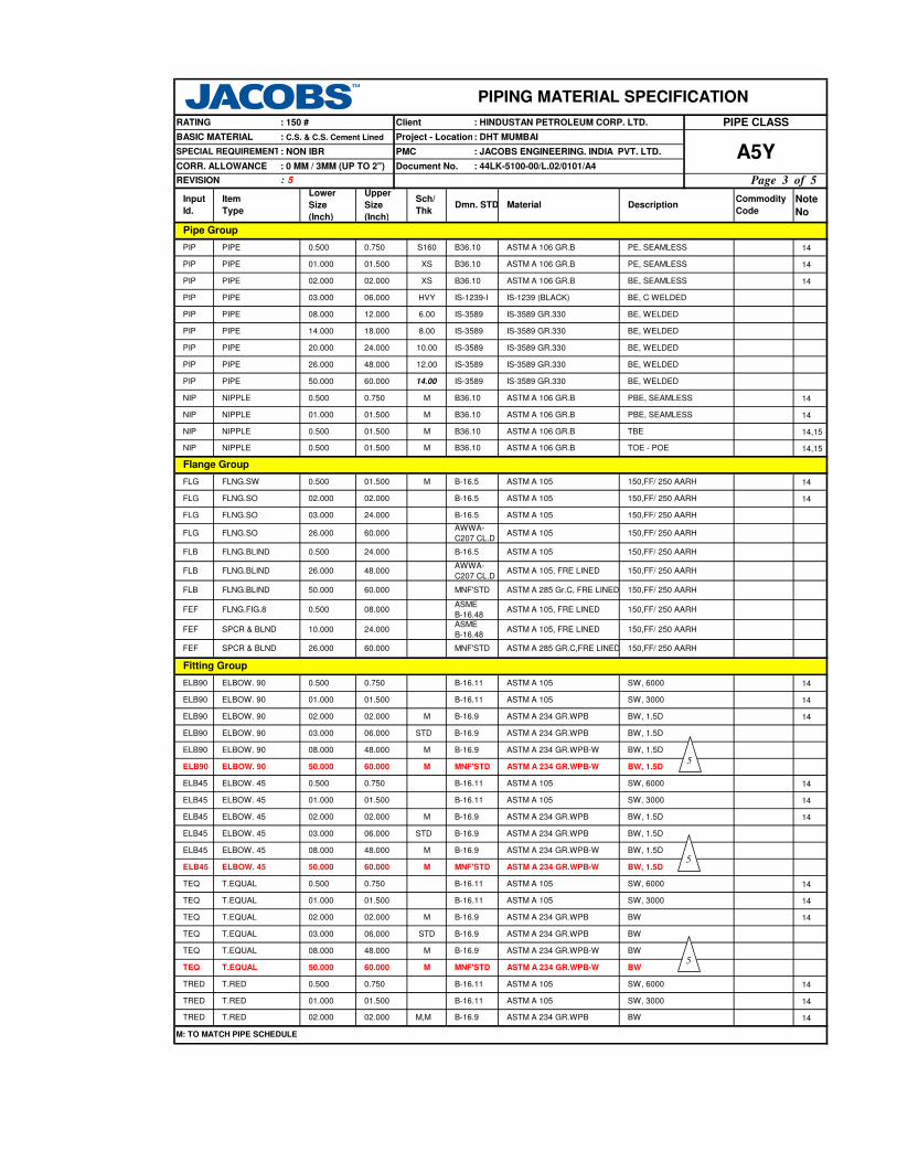
Note
No
14
14
14
14
14
14,15
14,15
14
14
14
14
14
14
14
14
14
14
14
14
14
14
NIP NIPPLE 0.500 01.500 M B36.10 ASTM A 106 GR.B TOE - POE
M B36.10 ASTM A 106 GR.B TBENIP NIPPLE 0.500 01.500
M MNF'STD ASTM A 234 GR.WPB-W BWTEQ T.EQUAL 50.000 60.000
ELB45 ELBOW. 45 50.000 60.000 M MNF'STD ASTM A 234 GR.WPB-W BW, 1.5D
M MNF'STD ASTM A 234 GR.WPB-W BW, 1.5DELB90 ELBOW. 90 50.000 60.000
M: TO MATCH PIPE SCHEDULE
ELB90 ELBOW. 90 08.000 48.000 M B-16.9 ASTM A 234 GR.WPB-W BW, 1.5D
ELB45 ELBOW. 45 08.000 48.000 M B-16.9 ASTM A 234 GR.WPB-W BW, 1.5D
M,M B-16.9 ASTM A 234 GR.WPB BWTRED T.RED 02.000 02.000
TEQ T.EQUAL 08.000 48.000 M B-16.9 ASTM A 234 GR.WPB-W BW
STD B-16.9 ASTM A 234 GR.WPB BWTEQ T.EQUAL 03.000 06.000
TEQ T.EQUAL 02.000 02.000 M B-16.9 ASTM A 234 GR.WPB BW
STD B-16.9 ASTM A 234 GR.WPB BW, 1.5DELB45 ELBOW. 45 03.000 06.000
ELB45 ELBOW. 45 02.000 02.000 M B-16.9 ASTM A 234 GR.WPB BW, 1.5D
FEF SPCR & BLND 10.000 24.000ASME
B-16.48ASTM A 105, FRE LINED 150,FF/ 250 AARH
ASME
B-16.48ASTM A 105, FRE LINED 150,FF/ 250 AARHFEF FLNG.FIG.8 0.500 08.000
FLB FLNG.BLIND 26.000 48.000AWWA-
C207 CL.DASTM A 105, FRE LINED 150,FF/ 250 AARH
FLB FLNG.BLIND 0.500 24.000
FLG FLNG.SO 03.000 24.000 B-16.5 ASTM A 105 150,FF/ 250 AARH
FLG FLNG.SO 26.000 60.000AWWA-
C207 CL.DASTM A 105 150,FF/ 250 AARH
12.00 IS-3589 IS-3589 GR.330 BE, WELDEDPIP PIPE 26.000 48.000
10.00 IS-3589 IS-3589 GR.330 BE, WELDEDPIP PIPE 20.000 24.000
8.00 IS-3589 IS-3589 GR.330 BE, WELDEDPIP PIPE 14.000 18.000
6.00 IS-3589 IS-3589 GR.330 BE, WELDEDPIP PIPE 08.000 12.000
PIP PIPE 03.000 06.000 HVY IS-1239-I IS-1239 (BLACK) BE, C WELDED
PIP PIPE 02.000 02.000
PIP PIPE 01.000 01.500
PE, SEAMLESS
BE, SEAMLESS
0.750
PE, SEAMLESS
ASTM A 106 GR.B PBE, SEAMLESS
XS B36.10 ASTM A 106 GR.B
XS B36.10 ASTM A 106 GR.B
S160 B36.10 ASTM A 106 GR.B
NIP NIPPLE 0.500 0.750
PIP PIPE 0.500
PIPING MATERIAL SPECIFICATION
ClientRATING : 150 #
TRED T.RED 0.500 0.750 B-16.11 ASTM A 105 SW, 6000
B-16.11 ASTM A 105 SW, 6000TEQ T.EQUAL 0.500 0.750
ELB45 ELBOW. 45 0.500 0.750
SW, 6000
B-16.11 ASTM A 105 SW, 6000
M B-16.9 ASTM A 234 GR.WPB
0.750 B-16.11 ASTM A 105
26.000 60.000
ELB90 ELBOW. 90 02.000 02.000
Fitting Group
ELB90 ELBOW. 90 0.500
BW, 1.5D
ELB90 ELBOW. 90 03.000 06.000 STD B-16.9 ASTM A 234 GR.WPB BW, 1.5D
Flange Group
FLG FLNG.SW 0.500 01.500 M
150,FF/ 250 AARHFEF SPCR & BLND
Dmn. STD DescriptionCommodity
CodeMaterial
Pipe Group
NIP 01.000
Lower
Size
(Inch)
Input
Id.
BASIC MATERIAL
SPECIAL REQUIREMENT
Item
Type
PMC
Project - Location
REVISION : 5
CORR. ALLOWANCE
: C.S. & C.S. Cement Lined
: NON IBR
: 0 MM / 3MM (UP TO 2")
NIPPLE PBE, SEAMLESS
Document No.
Sch/
Thk
Upper
Size
(Inch)
M B36.10
B36.1001.500 ASTM A 106 GR.BM
B-16.5 ASTM A 105 150,FF/ 250 AARH
MNF'STD ASTM A 285 GR.C,FRE LINED
B-16.5 ASTM A 105 150,FF/ 250 AARH
: HINDUSTAN PETROLEUM CORP. LTD. PIPE CLASS
: DHT MUMBAI
A5Y: JACOBS ENGINEERING. INDIA PVT. LTD.
: 44LK-5100-00/L.02/0101/A4
TRED T.RED 01.000 01.500 B-16.11 ASTM A 105 SW, 3000
B-16.11 ASTM A 105 SW, 3000TEQ T.EQUAL 01.000 01.500
ELB45 ELBOW. 45 01.000 01.500
ELBOW. 90 01.000 01.500
B-16.11 ASTM A 105 SW, 3000
B-16.11 ASTM A 105 SW, 3000ELB90
PIP PIPE 50.000 60.000 14.00 IS-3589 IS-3589 GR.330 BE, WELDED
FLB FLNG.BLIND 50.000 60.000 MNF'STD ASTM A 285 Gr.C, FRE LINED 150,FF/ 250 AARH
FLG FLNG.SO 02.000 02.000 B-16.5 ASTM A 105 150,FF/ 250 AARH
5
5
5
Page 3 of 5

Note
No
PIPING MATERIAL SPECIFICATION
ClientRATING : 150 #
Dmn. STD DescriptionCommodity
CodeMaterial
Lower
Size
(Inch)
Input
Id.
BASIC MATERIAL
SPECIAL REQUIREMENT
Item
Type
PMC
Project - Location
REVISION : 5
CORR. ALLOWANCE
: C.S. & C.S. Cement Lined
: NON IBR
: 0 MM / 3MM (UP TO 2") Document No.
Sch/
Thk
Upper
Size
(Inch)
: HINDUSTAN PETROLEUM CORP. LTD. PIPE CLASS
: DHT MUMBAI
A5Y: JACOBS ENGINEERING. INDIA PVT. LTD.
: 44LK-5100-00/L.02/0101/A4
14
14
14
14
14
14
14
14
14
14
14
TRED T.RED 50.000 60.000 M,M B-16.9 ASTM A 234 GR.WPB-W BW
Fitting Group
M: TO MATCH PIPE SCHEDULE
GAV VLV.GLOBE 02.000 16.000 BS-1873
BODY-ASTM A 216 Gr.WCB,
CORROCOATED
TRIM-BRONZE
FLGD, 150, B-16.5,
FF/250AARH, Tag No.
52385
BS-5155
BODY-ASTM A 216 Gr.WCB,
CORROCOATED
TRIM-BRONZE
FLGD, 150, AWWA C207,
FF/250AARH, Tag No.
56386
API-609/
BS-5155
FLGD, 150, B-16.5,WAF/
FF/250AARH, Tag No.
56385
IS:778 CL.2
BODY-IS 318 GR.2 LEADED
TIN BRONZE, TRIM-IS 320
ALLOY HT2
SCRF, CL.2, 3000,
B-1.20.1, Tag No. 53080
BODY-ASTM A 216 Gr.WCB,
CORROCOATED
TRIM-BRONZE
BFV VLV.BTRFLY 26.000 48.000
BFV VLV.BTRFLY 03.000 24.000
FLGD, 150, AWWA C207,
FF/250AARH, Tag No.
53386
BS-1868
BODY-ASTM A 216 Gr.WCB,
CORROCOATED
TRIM-BRONZE
CHV VLV.CHECK 0.500 01.500
CAP CAP 08.000 48.000 M B-16.9 ASTM A 234 GR.WPB BW
STD B-16.9 ASTM A 234 GR.WPB BWCAP CAP 03.000 06.000
CAP CAP 02.000 02.000 M B-16.9 ASTM A 234 GR.WPB BW
M,M MNF'STD IS-3589 GR.330 BWREDE REDUC.ECC 08.000 60.000
REDE REDUC.ECC 03.000 06.000STD,
STDB-16.9 ASTM A 234 GR.WPB BW
M,M B-16.9 ASTM A 234 GR.WPB BWREDE REDUC.ECC 02.000 02.000
REDC REDUC.CONC 08.000 60.000 M,M MNF'STD IS-3589 GR.330 BW
STD,
STDB-16.9 ASTM A 234 GR.WPB BWREDC REDUC.CONC 03.000 06.000
REDC REDUC.CONC 02.000 02.000 M,M B-16.9 ASTM A 234 GR.WPB BW
M,M B-16.9 ASTM A 234 GR.WPB-W BWTRED T.RED 08.000 48.000
TRED T.RED 03.000 06.000 STD B-16.9 ASTM A 234 GR.WPB BW
GAV
CPLF CPLNG.FULL 01.000 01.500 B-16.11 ASTM A 105
GAV
VLV.GLOBEGAV
FLGD,150, B16.5,
FF/250AARH, Tag No.
51385
BODY-ASTM A 216 Gr.WCB,
CORROCOATED
TRIM-BRONZE
API-60024.00002.000VLV.GATE
SCRF, CL.2, 3000,
B-1.20.1, Tag No. 52080
SWGC SWAGE.CONC 0.500 03.000
Valves Group
SW, 3000
CPLH CPLNG.HALF 01.000 01.500
VLV.CHECK API-594
0.500
CHV
VLV.GATE 0.500 01.500
26.000 48.000
01.500
SCRF, CL.2, 3000,
B-1.20.1, Tag No. 51080
IS:778 CL.2
BODY-IS 318 GR.2 LEADED
TIN BRONZE, TRIM-IS 320
ALLOY HT2
IS:778 CL.2
BODY-IS 318 GR.2 LEADED
TIN BRONZE, TRIM-IS 320
ALLOY HT2
FLGD, 150, B-16.5,
FF/250AARH, Tag No.
53385
BODY-ASTM A 105 / A216
GR.WCB, CORROCOATED
TRIM-BRONZE
B-16.11 ASTM A 105 SW, 6000
SW, 3000B-16.11 ASTM A 105
CPLF CPLNG.FULL 00.500 00.750
CAP CAP 0.500 0.750
M,M BS-3799 ASTM A 105 PBE
B-16.11 ASTM A 105 SW, 6000
CPLH CPLNG.HALF 00.500 00.750 B-16.11 ASTM A 105 SW, 6000
CAP CAP 01.000 01.500 B-16.11 ASTM A 105 SW, 3000
SWGE SWAGE.ECC 0.500 03.000 M,M BS-3799 ASTM A 105 PBE
CHV VLV.CHECK 02.000 24.000
5
Page 4 of 5

Note
No
PIPING MATERIAL SPECIFICATION
ClientRATING : 150 #
Dmn. STD DescriptionCommodity
CodeMaterial
Lower
Size
(Inch)
Input
Id.
BASIC MATERIAL
SPECIAL REQUIREMENT
Item
Type
PMC
Project - Location
REVISION : 5
CORR. ALLOWANCE
: C.S. & C.S. Cement Lined
: NON IBR
: 0 MM / 3MM (UP TO 2") Document No.
Sch/
Thk
Upper
Size
(Inch)
: HINDUSTAN PETROLEUM CORP. LTD. PIPE CLASS
: DHT MUMBAI
A5Y: JACOBS ENGINEERING. INDIA PVT. LTD.
: 44LK-5100-00/L.02/0101/A4
MNF'STDB:A216 GR.WCB (GALV);
INT: BRONZE
FLANGED, Y-TYPE,
150, FF/250AARH
Trap/Strainer Group
TSR STRNR.TEMP 03.000 24.000 MNF'STDB:A285 Gr.C GALV,
INT: BRONZE
CONE TYPE, 150,
FF/250AARH
PSR STRNR.PERM 03.000 24.000
GAS GASKET 26.000 60.000AWWA-
C207 CL.DBuna-N (Nitrile) FULLFACE, 150, 2MM
M: TO MATCH PIPE SCHEDULE
B-16.21-
ANSI B
16.5
16.000 B-18.2BOLT:A307 GR.B, GALV
NUT: A563 GR.B, GALV
Buna-N (Nitrile) FULLFACE, 150,2MM
Bolt Group
BOM BOLT.M/C 0.500
GAS GASKET 0.500 24.000
Gasket Group
B-18.2BOLT:A193 GR.B7,GALV
NUT: A194 GR.2H, GALVBOS BOLT.STUD 18.000 60.000
Page 5 of 5

NOTES
6 . ASBESTOS FREE GASKETS AND STEM PACKING SHALL BE USED FOR VALVES.
7 . RTJ FLANGE WITH OCTAGONAL RING GASKET SHALL BE USED FOR ROV IN MOUNDED BULLET AREA AS PER P&ID REQUIREMENT.
5 . NON DESTRUCTIVE EXAMINATION REQUIREMENT FOR CARBON STEEL PIPING CLASSES SHALL BE STRINGENT OF
JACOBS STANDARD 44LK-5100-00/L.02/0103/A4 & LICENSOR'S REQUIREMENT.
AMMONIA, SWEET GAS, FLUSHING OIL AND OTHER UTILITIES - MP CONDENSATE, INTRUMENT AIR; PLANT AIR;
3 . FOR RESTRICTION ON THE USE OF BALL, PLUG & BUTTERFLY VALVES, REFER GENERAL NOTES.
4 . CORROSIVE ALLOWANCE HAS BEEN ADJUSTED TO SELECT OPTIMUM SCHEDULE REFER GENERAL NOTES TO PMS.
B1A
Page 1 of 4
: DHT MUMBAI
CORR. ALLOWANCE
PMC
Document No.: 1.5 MM
SPECIAL REQUIREMENT : - : JACOBS ENGINEERING. INDIA PVT. LTD.
: 44LK-5100-00/L.02/0101/A4
Project - Location
PIPING MATERIAL SPECIFICATION
ClientRATING : 300 #
BASIC MATERIAL : CARBON STEEL
PIPE CLASS: HINDUSTAN PETROLEUM CORP. LTD.
: 2
TEMPERATURE ( Deg. C ) AND PRESSURE ( Kg/Sq. cm g ) RATINGS
38.0 399.0
REVISION
371.0149.0 427.0343.0
VENTS ON LINES <=1.5"
ON LINES >= 2"
ON LINES <=1.5"DRAINS
2" AND ABOVE
ON LINES >= 2"
0.75"
TEMP. CONN. 1.5"
PRESS. CONN.
42.18 35.50
204.0
SERVICE
2 . FOR STRAINERS AND SPACER & BLINDS,REFER JACOBS STANDARD DRAWINGS.
28.8252.02
93.0 316.0260.0
38.66 37.61 37.6147.45 44.64
SIZE
ALLMAINT. JOINTS FLANGED, TO BE KEPT MINIMUM
A. CODEDESCRIPTION
PIPE JOINTS 1.5" AND BELOW
1. NDT REQUIREMENT SHALL BE AS PER JACOBS STANDARD 44LK-5100-00/L.02/0103/A4.
NON CORROSIVE / FLAMMABLE / NON FLAMMABLE / NON LETHAL- HYDROCARBONS, AROMATICS,
ITEM
NITROGEN, AMMONIA GAS ETC ABOVE CLASS 'A1A', FUEL OIL (HSFO & LSFO)
-29.0
PRESS 46.0552.02
TEMP
SPECIAL NOTES
REFER JACOBS STD. 44LK-5100-0350, VF3.
SW NIPPLE WITH VALVE TO SPEC. AS PER 44LK-5100-0354
AS PER P& ID OR 0.75". REFER JACOBS STD. 44LK-5100-0351, V4.
FLANGED, REFER JACOBS STD. 44LK-5100-0353.
AS PER P& ID OR 0.75". REFER JACOBS STD. 44LK-5100-0351, D4.
SW COUPLNG
REFER JACOBS STD. 44LK-5100-0350, DF3.
BUTT WELDED
2

PMC : JACOBS ENGINEERING. INDIA PVT. LTD.
Document No. : 44LK-5100-00/L.02/0101/A4
BRANCH CONNECTIONS
48
46
44
42
40
38
36
34
32
30
28
26
24
22
T 20
T R 18
T R R 16
T R R R 14
T R R R R 12
T R R R R R 10
T R R R R R R 8
T R R R R R R R 6
5
T R R R R R R R R 4
3½
T P R R R R R R R R 3
2½
T P R R R R R R R R R 2
T T H H H H H H H H H H 1½
1¼
T T H H H H H H H H H H H 1
T T T H H H H H H H H H H H ¾
T T T T H H H H H H H H H H H ½
¼
¼ ½ ¾ 1 1¼
1½ 2 2½ 3 3½ 4 5 6 8 10
12
14
16
18
20
22
24
26
28
30
32
34
36
38
40
42
44
46
48
Page 2 of 4
: HINDUSTAN PETROLEUM CORP. LTD.
: DHT MUMBAI
PIPING MATERIAL SPECIFICATION
Client
SPECIAL REQUIREMENT
: 300 #
Project - Location
RATING PIPE CLASS
B1A: 1.5 MM
BASIC MATERIAL : CARBON STEEL
CORR. ALLOWANCE
: -
BR
AN
CH
PIP
E N
B
INSTRUMENT TEE
T
X
I
R
F SADDLE FUSED JT
P
REVISION : 2
J THREADOLET
WELDOLETS
S
H H. COUPLING
SOCKOLETS
PIPE TO PIPE
REINFORCED
L SWEEPOLET
W
Refer Notes
RUN PIPE NB
CODE DESCRIPTION
TEES

PMC : JACOBS ENGINEERING. INDIA PVT. LTD.
Document No. : 44LK-5100-00/L.02/0101/A4
Note
No
4
7
FLG FLNG. WN 02.000 24.000 M B-16.5 ASTM A 105 300, RF/125AARH
PIP PIPE 16.000 18.000 XS B-36.10 ASTM A 672 GR.B60 CL.12 BE, E.FS.W
STD B-36.10 ASTM A 106 GR.B BE, SEAMLESSPIP PIPE 12.000 14.000
CPLF 0.500 01.500 B-16.11 ASTM A 105 SW, 3000
B-16.5 ASTM A 105 300, RF/125AARH
PBE
FLG/30 FLNG. WN 02.000 24.000 M B-16.5 ASTM A 105 300, RTJ/63AARH
01.500
03.000
01.500
REDUC.CONC
02.000 14.000
14.000
CAP CAP 02.000
SWGE SWAGE.ECC 0.500
FLG
24.000 M, MREDE REDUC.ECC
M
M, M
24.000 M, M
M, M
PIPING MATERIAL SPECIFICATION
Client : HINDUSTAN PETROLEUM CORP. LTD.RATING : 300 # PIPE CLASS
24.000 M
M, M
BS-3799 ASTM A 105
BW
B-16.9 ASTM A 234 GR.WPB-W BW
PBE
B-16.9 ASTM A 234 GR.WPB
BS-3799 ASTM A 105
M, M B-16.9 ASTM A 234 GR.WPB BW
BW
B-16.9 BWASTM A 234 GR.WPB
B-16.9 ASTM A 234 GR.WPB-W
B-16.9 BW
M, M
REDE REDUC.ECC 02.000 14.000
SWGC SWAGE.CONC 0.500 03.000
16.000
TRED T.RED
24.000
14.000
TRED T.RED
B-16.11TRED T.RED 0.500 01.500 ASTM A 105 SW,3000
ASTM A 234 GR.WPB
TEQ T.EQUAL 16.000 24.000 M B-16.9 ASTM A 234 GR.WPB-W BW
M B-16.9 ASTM A 234 GR.WPB BWTEQ T.EQUAL 02.000 14.000
TEQ T.EQUAL 0.500 01.500 B-16.11 ASTM A 105 SW, 3000
ELB45 ELBOW.45 16.000 24.000 M B-16.9 ASTM A 234 GR.WPB-W BW, 1.5D
M B-16.9 ASTM A 234 GR.WPB BW, 1.5DELB45 ELBOW.45 02.000 14.000
ASTM A 105 300, FF/125AARH
ASTM A 105 300, FF/125AARH
B-16.11
24.000
ASME
B-16.48
ASTM A 105
Fitting Group
FEF SPCR & BLND
01.500 SW, 3000
10.000
01.500
B-16.5 ASTM A 105 300, RF/125AARH
Flange Group
ASME
B-16.48
SPECIAL REQUIREMENT
Project - Location
Lower
Size
(Inch)
Upper
Size
(Inch)
BASIC MATERIAL
: -
REVISION : 2
Sch/
Thk
Commodity
Code
: DHT MUMBAI
Material
Pipe Group
CORR. ALLOWANCE
: CARBON STEEL
: 1.5 MM
Dmn. STDInput
Id.
B1A
DescriptionItem
Type
FEF FLNG.FIG.8 0.500 08.000
M B-36.10 ASTM A 106 GR.B PBE, SEAMLESSNIP
ELB90 ELBOW.90 0.500
NIPPLE 0.500
FLB FLNG.BLIND 0.500
FLNG. SW 0.500
ELB90 ELBOW.90 02.000 14.000 M B-16.9 ASTM A 234 GR.WPB BW, 1.5D
B-16.9 ASTM A 234 GR.WPB-W BW, 1.5DELB90 ELBOW.90 16.000 24.000
ELB45 ELBOW.45 0.500 01.500
M
M,M B-16.9 BW
B-16.11 ASTM A 105 SW,3000
ASTM A 234 GR.WPB-W
CPLNG.FULL
16.000
16.000
REDC REDUC.CONC 02.000
REDC
M: TO MATCH PIPE SCHEDULE.
PIP PIPE 0.500 01.500 XS B-36.10 ASTM A 106 GR.B PE, SEAMLESS
PIP PIPE 02.000 06.000 STD B-36.10 ASTM A 106 GR.B BE, SEAMLESS
PIP PIPE 08.000 10.000 S30 B-36.10 ASTM A 106 GR.B BE, SEAMLESS
PIP PIPE 20.000 20.000 XS B-36.10 ASTM A 672 GR.B60 CL.12 BE, E.FS.W
0.500CPLNG.HALFCPLH SW, 3000ASTM A 105B-16.11
Page 3 of 4

PMC : JACOBS ENGINEERING. INDIA PVT. LTD.
Document No. : 44LK-5100-00/L.02/0101/A4
Note
No
PIPING MATERIAL SPECIFICATION
Client : HINDUSTAN PETROLEUM CORP. LTD.RATING : 300 # PIPE CLASS
SPECIAL REQUIREMENT
Project - Location
Lower
Size
(Inch)
Upper
Size
(Inch)
BASIC MATERIAL
: -
REVISION : 2
Sch/
Thk
Commodity
Code
: DHT MUMBAI
Material
CORR. ALLOWANCE
: CARBON STEEL
: 1.5 MM
Dmn. STDInput
Id.
B1A
DescriptionItem
Type
7
API-602BODY-ASTM A 105,
TRIM-8
SW,800,3000,B 16.11,
Tag No. 51001VLV. GATE 0.500 01.500
BLV VLV.BALL 0.500
GAV
CHV VLV.CHECK 02.000
GLV VLV. GLOBE 02.000
STUD:A193 GR.B7,
NUT:A194 GR.2H
Bolt Group
Gasket Group
BOS STUD / NUTS 0.500 24.000 B-18.2
24.000
BS-5351
BODY-ASTM A 105/A 216 GR.WCB,
TRIM - BODY SEAT - RPTFE16.000
BS-1868BODY-ASTM A 216 GR.WCB,
TRIM-8
FLGD,300,B-16.5,
RF/125AARH, Tag No.
53401
CHV VLV.CHECK 0.500 01.500 BS-5352BODY-ASTM A 105,
TRIM-8
SW,800,3000,B 16.11,
Tag No. 53001
BS-1873BODY-ASTM A 216 GR.WCB,
TRIM-8
FLGD,300,B-16.5,
RF/125AARH, Tag No.
52401
12.000
GLV VLV. GLOBE 0.500 01.500 BS-5352BODY-ASTM A 105,
TRIM-8
SW,800,3000,B 16.11,
Tag No. 52001
Valves Group
FLGD,300,B-16.5,
RF/125AARH, Tag No.
51401
GAV VLV. GATE 02.000 24.000 API-600BODY-ASTM A 216 GR.WCB,
TRIM-8
MNF'STD B:A105 ; INT: SS304 SW,Y TYPE,800
MNF'STD B:A105;T:13% CR; S: SS304FLGD,THRMDNMC,
300, RF/125AARH
MNF'STD B:A516 GR.70 ; INT: SS304CONE TYPE 300,
FF/125 AARH
PSR STRNR.PERM 0.500 01.500
TSR STRNR.TEMP 01.500 24.000
FLGD,300,B-16.5,
RF/125AARH, Tag No.
55401
M: TO MATCH PIPE SCHEDULE.
FLGD,300,B-16.5,
RF/125AARH, Tag No.
54401
PLV VLV.PLUG 0.500 24.000BS-5353
BODY-ASTM A 105/ A 216 GR.WCB,
TRIM-PLUG - HARDENED
Trap/Strainer Group
TRP TRAP STEAM 0.5000 1.500
M MNF'STDB:A234GR.WPB;
INT: SS304BW, T- TYPEPSR STRNR.PERM 02.000 14.000
PSR STRNR.PERM 16.000 24.000 M MNF'STDB:A234GR.WPBW;
INT: SS304BW, T- TYPE
B-16.20,
ANSI B16.5SOFT IRON OCT-RING, 300GAS/30 GASKET 02.000 24.000
CHV VLV.CHECK 0.500 01.500 MNF'STDBODY-ASTM A 105,
TRIM-8
FLGD,300,B-16.5,
RF/125AARH, Tag No.
53492
BLV VLV.BALL 0.500 01.000BS-5351
BODY-ASTM A 105/A 216 GR.WCB,
TRIM-SEAT- RPTFE
FLGD,300,B-16.5,
RF/125AARH, Tag No.
54492
B-16.20,
ANSI B16.5SP.WND SS316 + GRAFIL SPIRAL,300GAS GASKET 0.500 24.000
2
2
2
2
2
2
2
2
2
2
Page 4 of 4

AS PER P& ID OR 0.75". REFER JACOBS STD. 44LK-5100-0351, V1.
FLANGED, REFER JACOBS STD. 44LK-5100-0353.
BUTT WELDED
SPECIAL NOTES
2 . FOR STRAINERS AND SPACER & BLINDS,REFER JACOBS STANDARD DRAWINGS.
3 . FOR RESTRICTION ON THE USE OF BALL, PLUG & BUTTERFLY VALVES, REFER GENERAL NOTES.
PRESS 46.0552.02 44.64
REFER JACOBS STD. 44LK-5100-0350, VC1.
SW, SH HVY NIPPLE WITH GATE VALVE TO SPEC. AS PER 44LK-5100-0354
FLANGED, TO BE KEPT MINIMUM
DESCRIPTION
1.5" AND BELOW
2" AND ABOVE
REFER JACOBS STD. 44LK-5100-0350, DF3.
47.45
-29.0
HYDROGEN AND HYDROGEN BEARING HYDROCARBONS - FLAMMABLE,TOXIC/NON-TOXIC BUT NON-LETHAL.
204.0
ITEM A. CODESIZE
4 . FOR HYDROGEN SERVICE,CARBON STEEL PIPING MATERAILS WITH WALL THICKNESS3/8 INCH AND OVER SHALL BE NORMALISED.
SERVICE
52.02
93.0 260.0
42.18
TEMP
ON LINES >= 2"
0.75"
TEMP. CONN. 1.5"
PRESS. CONN.
ON LINES <=1.5"
ON LINES >= 2"
ON LINES <=1.5"DRAINS
VENTS
: 2
TEMPERATURE ( Deg. C ) AND PRESSURE ( Kg/Sq. cm g ) RATINGS
38.0
REVISION
149.0
Project - Location
PIPING MATERIAL SPECIFICATION
ClientRATING : 300 #
BASIC MATERIAL : CARBON STEEL
PIPE CLASS: HINDUSTAN PETROLEUM CORP. LTD.
CORR. ALLOWANCE
PMC
Document No.: 1.5 MM
SPECIAL REQUIREMENT : HYDROGEN SERVICE : JACOBS ENGINEERING. INDIA PVT. LTD.
: 44LK-5100-00/L.02/0101/A4B5A
Page 1 of 4
: DHT MUMBAI
NOTES
7 . ASBESTOS FREE GASKETS AND STEM PACKING SHALL BE USED FOR VALVES.
6 . NON DESTRUCTIVE EXAMINATION REQUIREMENT FOR CARBON STEEL PIPING CLASSES SHALL BE STRINGENT OF
JACOBS STANDARD 44LK-5100-00/L.02/0103/A4 & LICENSOR'S REQUIREMENT.
1 . NDT REQUIREMENT SHALL BE AS PER JACOBS STANDARD 44LK-5100-00/L.02/0103/A4.
5 . ANY MEDIUM CONTAINING HYDROGEN GAS WITH A PARTIAL PRESSURE OF 100 PSI & ABOVE SHALL BE CONSIDERED AS HYDROGEN SERVICE.
ALLMAINT. JOINTS
AS PER P& ID OR 0.75". REFER JACOBS STD. 44LK-5100-0351, D4.
SW COUPLNG 3000 LBS.PIPE JOINTS

48
44
42
40
36
34
32
30
26
T 24
T 22
T R R 20
T R R R 18
T R R R R 16
T R R R R R 14
T R R R R R R 12
T R R R R R R R 10
T R R R R R R R R 8
T R R R R R R R R R 6
5
T R R R R R R R R R R 4
3½
T R R R R R R R R R R R 3
2½
T R R R R R R R R R R R R 2
T T H H H H H H H H H H H H 1½
1¼
T T H H H H H H H H H H H H H 1
T T T H H H H H H H H H H H H H ¾
T T T T H H H H H H H H H H H H H ½
¼
¼ ½ ¾ 1 1¼
1½ 2 2½ 3 3½ 4 5 6 8 10
12
14
16
18
20
22
24
26
30
32
34
36
40
42
44
48
CODE DESCRIPTION
F SADDLE FUSED JT T TEES
H H. COUPLING W WELDOLETS
P PIPE TO PIPE I INSTRUMENT TEE
R REINFORCED X Refer Notes
S SOCKOLETS L SWEEPOLET
J
RUN PIPE NB
BR
AN
CH
PIP
E N
B
Page 2 of 4
BRANCH CONNECTIONS
BASIC MATERIAL : CARBON STEEL
REVISION : 2
: HYDROGEN
SERVICE
: 1.5 MMCORR. ALLOWANCE
B5AProject - Location: DHT MUMBAI
: 44LK-5100-00/L.02/0101/A4Document No.
: JACOBS ENGINEERING. INDIA PVT. LTD.
THREADOLET
PIPING MATERIAL SPECIFICATION
Client
SPECIAL REQUIREMENT PMC
RATING : 300 # : HINDUSTAN PETROLEUM CORP. LTD. PIPE CLASS

Note
No
M: TO MATCH PIPE SCHEDULE.
FLNG.WN 02.000 24.000 M B-16.5 ASTM A 105 300, RF/125AARH
B-16.9 ASTM A 234 GR.WPB
PIPE CLASS
BW, 1.5D
Fitting Group
Flange Group
FEF SPCR&BLND
FLG
10.000
REDE B-16.9REDUC.ECC 16.000 24.000
M
M, M
B-16.9
PIPING MATERIAL SPECIFICATION
: DHT MUMBAI
Client : HINDUSTAN PETROLEUM CORP. LTD.RATING
: CARBON STEEL
: 300 #
B5A: 44LK-5100-00/L.02/0101/A4
M, M
REDUC.CONC 16.000 24.000 B-16.9M, M
BW
BW
BW
ASTM A 234 GR.WPB BW
CPLH CPLNG.HALF 0.500 01.500 B-16.11 ASTM A 105 SW, 3000
B-16.11 ASTM A 105 SW, 3000CPLF CPLNG.FULL 0.500 01.500
CAP CAP 02.000 24.000
SWGE SWAGE.ECC 0.500 03.000
REDE REDUC.ECC
M, M BS-3799 ASTM A 105 PBE
BS-3799 ASTM A 105 PBE
SWGC SWAGE.CONC 0.500 03.000
BW02.000 14.000 B-16.9 ASTM A 234 GR.WPBM, M
BWASTM A 234 GR.WPB-W
ASTM A 234 GR.WPB-W
02.000 14.000 B-16.9 ASTM A 234 GR.WPB
TRED T.RED 02.000 14.000
TRED T.RED 0.500 01.500
M B-16.9 ASTM A 234 GR.WPB-W BW
B-16.11 ASTM A 105 SW, 3000
TEQ T.EQUAL 16.000 24.000
M B-16.9 ASTM A 234 GR.WPB BWTEQ T.EQUAL 02.000 14.000
TEQ T.EQUAL 0.500 01.500 B-16.11 ASTM A 105 SW, 3000
24.000ASME
B-16.48ASTM A 105 300, FF/125AARH
FEF FLNG.FIG.8 0.500 08.000ASME
B-16.48ASTM A 105 300, FF/125AARH
300, RF/125AARH
FLB FLNG.BLIND 0.500 24.000 B-16.5 ASTM A 105 300, RF/125AARH
FLG FLNG. SW 0.500 01.500
STD
M B-36.10 ASTM A 106 GR.B PBE, SEAMLESS
M B-16.5 ASTM A 105
NIP NIPPLE 0.500 01.500
B-36.10 ASTM A 106 GR.B BE, SEAMLESS
ASTM A 672 GR.B60 CL.32 BE, E.FS.WB-36.10PIP PIPE 16.000 24.000
Commodity
CodeMaterialDmn. STD
Sch/
Thk
STD
Project - Location
: HYDROGEN
SERVICEPMC
B-36.10
Item
Type
STD
XS
B-36.10
B-36.10PIP 0.500PIPE PE, SEAMLESS01.500
REVISION : 2
Lower
Size
(Inch)
Upper
Size
(Inch)
Input
Id.
S30
PIP PIPE
PIP PIPE 08.000 10.000
02.000 06.000
: JACOBS ENGINEERING. INDIA PVT. LTD.
BASIC MATERIAL
ASTM A 106 GR.B
SPECIAL REQUIREMENT
Document No.CORR. ALLOWANCE : 1.5 MM
Pipe Group
Description
BE, SEAMLESS
ASTM A 106 GR.B BE, SEAMLESS
ASTM A 106 GR.B
PIP PIPE 12.000 14.000
ELB90 ELBOW.90
B-16.9
ELB45 ELBOW.45 02.000 14.000
ELB45 M
M
ELBOW.45 16.000 24.000
0.500 01.500 B-16.11 ASTM A 105 SW, 3000
ELB90 ELBOW.90 02.000 14.000 M B-16.9 ASTM A 234 GR.WPB BW, 1.5D
ELB90 ELBOW.90 16.000 24.000 M B-16.9 ASTM A 234 GR.WPB-W BW, 1.5D
ELB45 ELBOW.45 0.500 01.500
BW, 1.5D
SW, 3000
M, M B-16.9
ASTM A 234 GR.WPB-W
B-16.11 ASTM A 105
B-16.9 ASTM A 234 GR.WPB-W BW
M, M
REDC
TRED T.RED
REDC REDUC.CONC
16.000 24.000 M, M
ASTM A 234 GR.WPB
2
Page 3 of 4

Note
No
PIPE CLASS
PIPING MATERIAL SPECIFICATION
: DHT MUMBAI
Client : HINDUSTAN PETROLEUM CORP. LTD.RATING
: CARBON STEEL
: 300 #
B5A: 44LK-5100-00/L.02/0101/A4
Commodity
CodeMaterialDmn. STD
Sch/
Thk
Project - Location
: HYDROGEN
SERVICEPMC
Item
Type
REVISION : 2
Lower
Size
(Inch)
Upper
Size
(Inch)
Input
Id.
: JACOBS ENGINEERING. INDIA PVT. LTD.
BASIC MATERIAL
SPECIAL REQUIREMENT
Document No.CORR. ALLOWANCE : 1.5 MM
Description
M MNF' STDB: A 234 GR.WPBW;
INT: SS 304BW, T- TYPEPSR STRNR.PERM 16.000 24.000
Gasket Group
BOS BOLT. STUD B-18.2
BODY-ASTM A 216 GR.WCB,
TRIM-8
FLGD, 300, B-16.5,
RF/125AARH, Tag
No.53404
SW, 800, 3000,
B-16.11, Tag No.
52004
SW, 800, 3000,
B-16.11, Tag No.
53004
FLGD, 300, B-16.5,
RF/125AARH, Tag
No.52404
GLV VLV. GLOBE
CHV VLV.CHECK 0.500 01.500
BLV
0.500 24.000BOLT:A193 GR.B7,
NUT:A194 GR.2H
Bolt Group
VLV.BALLBODY-ASTM A105/ A 216 GR.WCB,
TRIM-BODY SEAT-RPTFE
FLGD, 300, B-16.5,
RF/125AARH, Tag
No.54404
CHV VLV.CHECK 02.000 24.000 BS-1868
0.500
BS-5352
16.000 BS-5351
BODY-ASTM A 105,
TRIM-8
02.000 12.000 BS-1873BODY-ASTM A 216 GR.WCB,
TRIM-8
GLV VLV. GLOBE 0.500 01.500 BS-5352 BODY-ASTM A 105, TRIM-8
API-600BODY-ASTM A 216 GR.WCB,
TRIM-8
FLGD, 300, B-16.5,
RF/125AARH, Tag
No. 51404
GAV VLV. GATE 02.000 24.000
Valves Group
API-602 BODY-ASTM A 105, TRIM-8
SW, 800, 3000,
B-16.11, Tag No.
51004
GAV VLV. GATE 0.500 01.500
PSR STRNR.PERM 02.000 14.000 M MNF' STDB: A 234 GR.WPB;
INT: SS 304BW, T- TYPE
MNF' STD B: A 105; INT: SS 304 SW, Y-TYPE, 800PSR STRNR.PERM 0.500 01.500
Trap/Strainer Group
B-16.20,
ANSI B16.5SP.WND SS316 + GRAFOIL + I RING SPIRAL, 300GAS GASKET 0.500 24.000
M: TO MATCH PIPE SCHEDULE.
2
2
2
2
2
2
2
Page 4 of 4

Project - Location
51.09 45.99
1 NDT REQUIREMENT SHALL BE AS PER JOB SPECIFICATION 44LK-5100-00/L.02/0103/A4.
: DHT MUMBAI
B16A: JACOBS ENGINEERING. INDIA PVT. LTD.
: 44LK-5100-00/L.02/0101/A4
PIPING MATERIAL SPECIFICATION
ClientRATING : HINDUSTAN PETROLEUM CORP. LTD. PIPE CLASS: 300 #
A. CODEDESCRIPTION
FLANGED, TO BE KEPT MINIMUM
SW COUPLING
REFER JACOBS STD. 44LK-5100-0350, DF3.
Page 1 of 4
BUTT WELDED
2 FOR RESTRICTION ON USE OF BALL, PLUG & BUTTERFLY VALVES, REFER GENERAL NOTES TO PMS.
ON LINES ≤ 1.5"
2" AND ABOVE
AS PER P& ID OR 0.75". REFER JACOBS STD. 44LK-5100-0351, V4.
AS PER P& ID OR 0.75". REFER JACOBS STD. 44LK-5100-0351, D4.
PMC
Document No.
FLANGED, REFER JACOBS STD. 44LK-5100-0353.
SW NIPPLE WITH VALVE TO SPEC. AS PER 44LK-5100-0354
REFER JACOBS STD. 44LK-5100-0350, VF3.
ALL
47.52
NOTES
52.10
SPECIAL NOTES
: CARBON STEEL
: NACESPECIAL REQUIREMENT
38 10050
PRESS
BASIC MATERIAL
44.66 42.73
-29
ITEM
ON LINES ≥ 2"
0.75"
TEMP. CONN. 1.5"
PRESS. CONN.
SIZE
DRAINS
PIPE JOINTS 1.5" AND BELOW
52.10
MAINT. JOINTS
RICH AMINE, SOUR WATER, NACE SERVICE.
REVISION
VENTS ON LINES ≤ 1.5"
ON LINES ≥ 2"
TEMPERATURE ( Deg. C ) AND PRESSURE ( Kg/Sq. cm g ) RATINGS
SERVICE
CORR. ALLOWANCE : 4.5 MM
250200150TEMP
: 3

T 12
T R 10
T R R 8
T R R R 6
5
T P P R R 4
3½
T P P P R R 3
2½
T P P P P P P 2
T T H H H H H H 1½
1¼
T T H H H H H H H 1
T T T H H H H H H H ¾
T T T T H H H H H H H ½
¼
¼ ½ ¾ 1 1¼
1½ 2 2½ 3 3½ 4 5 6 8 10
12
CODE DESCRIPTION
F SADDLE FUSED JT T TEES
H H. COUPLING W WELDOLETS
P PIPE TO PIPE I INSTRUMENT TEE
R REINFORCED X REFER NOTES
S SOCKOLETS L SWEEPOLET
J THREADOLET
: JACOBS ENGINEERING. INDIA PVT. LTD.
: 44LK-5100-00/L.02/0101/A4B16A
REVISION
RUN PIPE NB
Project - LocationBASIC MATERIAL : CARBON STEEL
: NACE
: 4.5 MM
BRANCH CONNECTIONS
Page 2 of 4: 3
BR
AN
CH
PIP
E N
B
PIPING MATERIAL SPECIFICATION
Client
SPECIAL REQUIREMENT PMC
RATING : 300 #
Document No.
: HINDUSTAN PETROLEUM CORP. LTD. PIPE CLASS
: DHT MUMBAI
CORR. ALLOWANCE

Note
No
: 300 #
BASIC MATERIAL
PIPE CLASS
M
M, M
B-16.11 ASTM A 105 SW, 6000
CAP
PIPING MATERIAL SPECIFICATION
: DHT MUMBAI
Client : HINDUSTAN PETROLEUM CORP. LTD.RATING
: CARBON STEEL
Fitting Group
ELB45 ELBOW.45 01.000
ASTM A 234 GR.WPB
BWM, M B-16.9 ASTM A 234 GR.WPB
M: TO MATCH PIPE SCHEDULE.
BW
BS-3799 ASTM A 105 PBE
B-16.9
B-16.9 ASTM A 234 GR.WPB
B-16.11 ASTM A 105 SW, 6000CPLH CPLNG.HALF 01.000 01.500
B-16.11 ASTM A 105 SW, 9000
B-16.11 ASTM A 105
CPLH CPLNG.HALF 0.500 0.750
SW, 6000CPLF CPLNG.FULL 01.000 01.500
CPLF CPLNG.FULL 0.500 0.750 B-16.11 ASTM A 105 SW, 9000
CAP 02.000 12.000
SWGE SWAGE.ECC 0.500 03.000
M, M BS-3799 ASTM A 105 PBESWGC SWAGE.CONC 0.500 03.000
Flange Group
BW
REDE REDUC.ECC 02.000 12.000
01.500
REDUC.CONC 02.000 12.000
TRED T.RED 01.000 01.500
REDC
TRED T.RED 0.500 0.750 B-16.11 ASTM A 105 SW,9000
TEQ T.EQUAL 02.000 12.000 M B-16.9 ASTM A 234 GR.WPB BW
B-16.11 ASTM A 105 SW, 6000TEQ T.EQUAL 01.000 01.500
TEQ T.EQUAL 0.500 0.750
M B-16.9
B-16.11 ASTM A 105 SW, 9000
ASTM A 234 GR.WPB BW, 1.5D
ASME
B-16.48ASTM A 105 300, FF/125AARHFEF SPCR&BLND 10.000 12.000
FEF FLNG.FIG.8 0.500 08.000ASME
B-16.48ASTM A 105 300, FF/125AARH
300, RF/125AARH
FLB FLNG.BLIND 0.500 12.000 B-16.5 ASTM A 105 300, RF/125AARH
FLG FLNG. SW 0.500 0.750
M B-36.10 ASTM A 106 GR.B PBE, SEAMLESS
M B-16.5 ASTM A 105
PBE, SEAMLESS
NIP NIPPLE 01.000 01.500
ASTM A 106 GR.B BE, SEAMLESS
NIP NIPPLE 0.500 0.750 M B-36.10 ASTM A 106 GR.B
DescriptionCommodity
CodeMaterial
B-36.10
XS
Sch/
Thk
0.750
01.500
S 160 B-36.10
B-36.10
: NACE PMC
Dmn. STD
: JACOBS ENGINEERING. INDIA PVT. LTD.
PIP PIPE
Input
Id.
Document No.CORR. ALLOWANCE : 4.5 MM
Pipe Group
Item
Type
S 160
XXS
B16A: 44LK-5100-00/L.02/0101/A4
SPECIAL REQUIREMENT
Project - Location
PIPE
Lower
Size
(Inch)
Upper
Size
(Inch)
B-36.10 ASTM A 106 GR.B PE, SEAMLESS
ASTM A 106 GR.B PE, SEAMLESS
REVISION : 3
PIP PIPE 01.000
PIP 0.500
02.000 02.000
PIP PIPE 04.000 12.000
ASTM A 106 GR.B BE, SEAMLESS
FLG FLNG. SW 01.000 01.500 M B-16.5 ASTM A 105 300, RF/125AARH
M B-16.5 ASTM A 105 300, RF/125AARH
ELB45 ELBOW.45 02.000 12.000
ELB90 ELBOW.90 0.500 0.750 B-16.11 ASTM A 105 SW, 9000
ELB90 ELBOW.90 01.000 01.500 B-16.11 ASTM A 105 SW, 6000
ELB90 ELBOW.90 02.000 12.000 M B-16.9 ASTM A 234 GR.WPB BW, 1.5D
ELB45 ELBOW.45 0.500 0.750 B-16.11 ASTM A 105 SW, 9000
B-16.11 ASTM A 105 SW,6000
B-16.9 ASTM A 234 GR.WPB BW
M, M
TRED T.RED 02.000 12.000 M, M
FLG FLNG. WN 02.000 12.000
Page 3 of 4
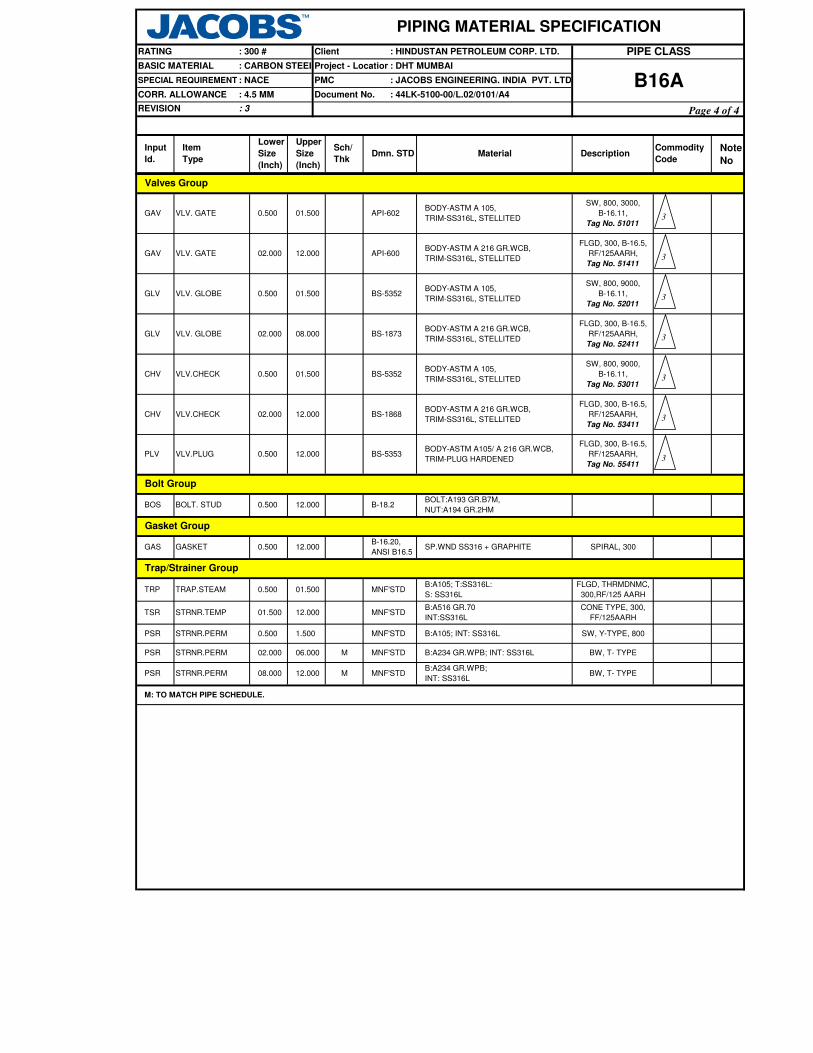
Note
No
: 300 #
BASIC MATERIAL
PIPE CLASS
PIPING MATERIAL SPECIFICATION
: DHT MUMBAI
Client : HINDUSTAN PETROLEUM CORP. LTD.RATING
: CARBON STEEL
DescriptionCommodity
CodeMaterial
Sch/
Thk
: NACE PMC
Dmn. STD
: JACOBS ENGINEERING. INDIA PVT. LTD.
Input
Id.
Document No.CORR. ALLOWANCE : 4.5 MM
Item
Type
B16A: 44LK-5100-00/L.02/0101/A4
SPECIAL REQUIREMENT
Project - Location
Lower
Size
(Inch)
Upper
Size
(Inch)
REVISION : 3
PSR STRNR.PERM 08.000 M MNF'STDB:A234 GR.WPB;
INT: SS316LBW, T- TYPE
BODY-ASTM A105/ A 216 GR.WCB,
TRIM-PLUG HARDENED
FLGD, 300, B-16.5,
RF/125AARH,
Tag No. 55411
FLGD, 300, B-16.5,
RF/125AARH,
Tag No. 52411
12.000
Gasket Group
BOS BOLT. STUD B-18.2
BS-535312.000
BS-5352BODY-ASTM A 105,
TRIM-SS316L, STELLITED
BODY-ASTM A 216 GR.WCB,
TRIM-SS316L, STELLITED
API-600BODY-ASTM A 216 GR.WCB,
TRIM-SS316L, STELLITED
API-602BODY-ASTM A 105,
TRIM-SS316L, STELLITED
MNF'STDB:A105; T:SS316L:
S: SS316L
B-16.20,
ANSI B16.5SP.WND SS316 + GRAPHITE
BS-1873
12.000
VLV.PLUG 0.500
TRP TRAP.STEAM 0.500 01.500FLGD, THRMDNMC,
300,RF/125 AARH
Bolt Group
BOLT:A193 GR.B7M,
NUT:A194 GR.2HM0.500
PLV
BODY-ASTM A 216 GR.WCB,
TRIM-SS316L, STELLITED
FLGD, 300, B-16.5,
RF/125AARH,
Tag No. 53411
CHV VLV.CHECK 02.000 12.000 BS-1868
SW, 800, 9000,
B-16.11,
Tag No. 53011
GLV VLV. GLOBE 02.000 08.000
0.500 01.500CHV VLV.CHECK
GLV VLV. GLOBE 0.500 01.500 BS-5352BODY-ASTM A 105,
TRIM-SS316L, STELLITED
SW, 800, 9000,
B-16.11,
Tag No. 52011
FLGD, 300, B-16.5,
RF/125AARH,
Tag No. 51411
GAV VLV. GATE 02.000 12.000
GAV VLV. GATE 0.500 01.500
SW, 800, 3000,
B-16.11,
Tag No. 51011
Valves Group
M MNF'STD B:A234 GR.WPB; INT: SS316L BW, T- TYPEPSR STRNR.PERM 02.000 06.000
PSR STRNR.PERM 0.500 1.500 MNF'STD B:A105; INT: SS316L SW, Y-TYPE, 800
Trap/Strainer Group
TSR STRNR.TEMP 01.500 12.000 MNF'STDB:A516 GR.70
INT:SS316L
CONE TYPE, 300,
FF/125AARH
SPIRAL, 300GAS GASKET 0.500 12.000
M: TO MATCH PIPE SCHEDULE.
3
3
3
3
3
3
3
Page 4 of 4

SPECIAL NOTES
REFER JACOBS STD. 44LK-5100-0350, VF3.
SW NIPPLE WITH VALVE TO SPEC. AS PER 44LK-5100-0354
AS PER P& ID OR 0.75". REFER JACOBS STD. 44LK-5100-0351, V4.
FLANGED, REFER JACOBS STD. 44LK-5100-0353.
AS PER P& ID OR 0.75". REFER JACOBS STD. 44LK-5100-0351, D4.
SW COUPLNG
REFER JACOBS STD. 44LK-5100-0350, DF3.
BUTT WELDED
-29.0
PRESS 46.0552.02
TEMP
PIPE JOINTS 1.5" AND BELOW
1. NDT REQUIREMENT SHALL BE AS PER JACOBS STANDARD 44LK-5100-00/L.02/0103/A4.
PROCESS WITH HYDROGEN, HYDROGEN
ITEM
7. THICKNESS SELECTED AS PER LICENSOR'S REQUIREMENT.
SIZE
ALLMAINT. JOINTS FLANGED, TO BE KEPT MINIMUM
A. CODEDESCRIPTION
47.45 44.64
9. ASBESTOS FREE GASKETS AND STEM PACKING SHALL BE USED FOR VALVES.
204.0
SERVICE
2. FOR STRAINERS AND SPACER & BLINDS,REFER JACOBS STANDARD DRAWINGS.
52.02
93.0 230.0
43.50
ON LINES >= 2"
0.75"
TEMP. CONN. 1.5"
PRESS. CONN.
VENTS ON LINES <=1.5"
ON LINES >= 2"
ON LINES <=1.5"DRAINS
2" AND ABOVE
: 1
TEMPERATURE ( Deg. C ) AND PRESSURE ( Kg/Sq. cm g ) RATINGS
38.0
REVISION
149.0
Project - Location
PIPING MATERIAL SPECIFICATION
ClientRATING : 300 #
BASIC MATERIAL : CARBON STEEL
PIPE CLASS: HINDUSTAN PETROLEUM CORP. LTD.
CORR. ALLOWANCE
PMC
Document No.: 3.0 MM
SPECIAL REQUIREMENT : HYDROGEN SERVICE : JACOBS ENGINEERING. INDIA PVT. LTD.
: 44LK-5100-00/L.02/0101/A4B52A
Page 1 of 4
: DHT MUMBAI
3. FOR RESTRICTION ON THE USE OF BALL, PLUG & BUTTERFLY VALVES, REFER GENERAL NOTES.
6. THIS ITEM IS SOLELY FOR USE BY INSTRUMENTATION.
5. ANY MEDIUM CONTAINING HYDROGEN GAS WITH A PARTIAL PRESSURE OF 100 PSI & ABOVE SHALL BE CONSIDERED AS HYDROGEN SERVICE.
NOTES
4. FOR HYDROGEN SERVICE, CARBON STEEL PIPING MATERIALS WITH WALL THICKNESS 3/8 INCH AND OVER SHALL BE NORMALISED.
8. NON DESTRUCTIVE EXAMINATION REQUIREMENT FOR CARBON STEEL PIPING CLASSES SHALL BE STRINGENT OF
JACOBS STANDARD 44LK-5100-00/L.02/0103/A4 & LICENSOR'S REQUIREMENT.
10. POST WELD HET TREATMENT REQUIRED FOR ALL THICKNESSES.

T 24
22T R 20
T R R 18T R R R 16
T R R R R 14T R R R R R 12
T R R R R R R 10T R R R R R R R 8
T R R R R R R R R 6
5T R R R R R R R R R 4
3½T R R R R R R R R R R 3
2½T R R R R R R R R R R R 2
T T H H H H H H H H H H H 1½
1¼T T H H H H H H H H H H H H 1
T T T H H H H H H H H H H H H ¾T T T T H H H H H H H H H H H H ½
¼
¼ ½ ¾ 1 1¼
1½ 2 2½ 3 3½ 4 5 6 8 10
12
14
16
18
20
22
24
INSTRUMENT TEE
Refer Notes
CODE
RUN PIPE NB
F
H
L SWEEPOLET
THREADOLET
TEESSADDLE FUSED JT
WELDOLETSH. COUPLING W
J
S SOCKOLETS
T
IPIPE TO PIPE
R REINFORCED X
P
BASIC MATERIAL : CARBON STEEL
SPECIAL REQUIREMENT
CORR. ALLOWANCE : 3.0 MM
: HYDROGEN
SERVICE
REVISION : 1
BR
AN
CH
PIP
E N
B
ClientRATING : 300 #
PIPING MATERIAL SPECIFICATION
: HINDUSTAN PETROLEUM CORP. LTD.
BRANCH CONNECTIONS
DESCRIPTION
Page 2 of 4
: DHT MUMBAI
: JACOBS ENGINEERING. INDIA PVT. LTD.
PIPE CLASS
B52AProject - Location
: 44LK-5100-00/L.02/0101/A4
PMC
Document No.

Note
No
7
7
PIPING MATERIAL SPECIFICATION
B52A
: HINDUSTAN PETROLEUM CORP. LTD.
: DHT MUMBAI
: JACOBS ENGINEERING. INDIA PVT.LTD.
: 44LK-5100-00/L.02/0101/A4
PIPE CLASSClient
REDC REDUC.CONC
SWGC SWAGE.CONC 0.500 03.000
SW, 6000
16.000 24.000
M, M B-16.9
M, M
0.500 01.500 ASTM A 105ELB45 ELBOW.45 B-16.11
ELB90 ELBOW. 90 16.000 24.000 M B-16.9 ASTM A 234 GR.WPB-W BW, 1.5D
M B-16.9 ASTM A 234 GR.WPB BW, 1.5DELB90 ELBOW. 90 02.000 14.000
B-36.10
STD B-36.10
BE, E.FS.W
S40
B-36.10
ASTM A 106 GR.B BE, SEAMLESS
ASTM A 672
GR.B60 CL.32BE, E.FS.W
ASTM A 672
GR.B60 CL.32
03.000 10.000 ASTM A 106 GR.B BE, SEAMLESS
ASTM A 106 GR.B BE, SEAMLESS
PE, SEAMLESS
STD B-36.10
B-36.10
CORR. ALLOWANCE : 3.0 MM
Dmn. STD
REVISION : 1
Document No.
Sch/
Thk
PIP PIPE
Item
Type
XS
S160
Lower
Size
(Inch)
Upper
Size
(Inch)
PIP 0.500 01.500
: CARBON STEELBASIC MATERIAL
DescriptionCommodity
CodeMaterial
Project - Location
SPECIAL REQUIREMENT: HYDROGEN
SERVICEPMC
Input
Id.
Pipe Group
ASTM A 106 GR.BPIPE
PIP PIPE 02.000 B-36.1002.000
PIP PIPE 12.000
PIP PIPE 16.000
Fitting Group
01.500 SW, 6000ASTM A 105B-16.11ELB90
MFLNG. SW
16.000
14.000
M
0.500 01.500
XS
ELBOW. 90 0.500
S30PIP PIPE 18.000 20.000
NIPPLE 0.500 01.500
B-16.5 ASTM A 105 300, RF/125AARH
B-36.10 ASTM A 106 GR.B PBE, SEAMLESS
Flange Group
FLG
NIP
FLG FLNG. WN 02.000 24.000 M B-16.5 ASTM A 105 300, RF/125AARH
B-16.5 ASTM A 105 300, RF/125AARHFLB FLNG.BLIND 0.500 24.000
FEF FLNG.FIG.8 0.500 08.000ASME
B-16.48ASTM A 105 300, FF/125AARH
FEF SPCR&BLND 10.000 24.000ASME
B-16.48ASTM A 105 300, FF/125AARH
ELB45 ELBOW.45 02.000 14.000 M B-16.9 ASTM A 234 GR.WPB BW, 1.5D
ELB45 ELBOW.45 16.000 24.000 M B-16.9 ASTM A 234 GR.WPB-W BW, 1.5D
BW
ASTM A 105TEQ T.EQUAL 0.500 01.500 B-16.11 SW, 6000
TEQ T.EQUAL 02.000 14.000 M B-16.9 ASTM A 234 GR.WPB
TEQ T.EQUAL 16.000 24.000 M B-16.9 ASTM A 234 GR.WPB-W BW
TRED T.RED 02.000 14.000
TRED T.RED 0.500 01.500
B-16.9 ASTM A 234 GR.WPB BW
SW, 6000B-16.11 ASTM A 105
TRED T.RED 16.000 24.000
M, M B-16.9ASTM A 234
GR.WPB- W
M, M B-16.9 ASTM A 234 GR.WPB-W BW
M, M
BW
BWASTM A 234 GR.WPBREDC REDUC.CONC 02.000 14.000
B-16.9 ASTM A 234 GR.WPB BWREDE REDUC.ECC 02.000 14.000
REDE REDUC.ECC 16.000 24.000 M, M B-16.9ASTM A 234
GR.WPB- WBW
M, M BS-3799 ASTM A 105 PBE
SWGE SWAGE.ECC 0.500 03.000 M, M BS-3799 ASTM A 105 PBE
M: TO MATCH PIPE SCHEDULE
RATING : 300 #
PIP PIPE 24.000 24.000 B-36.10ASTM A 672
GR.B60 CL.32BE, E.FS.W
1
1
1
Page 3 of 4
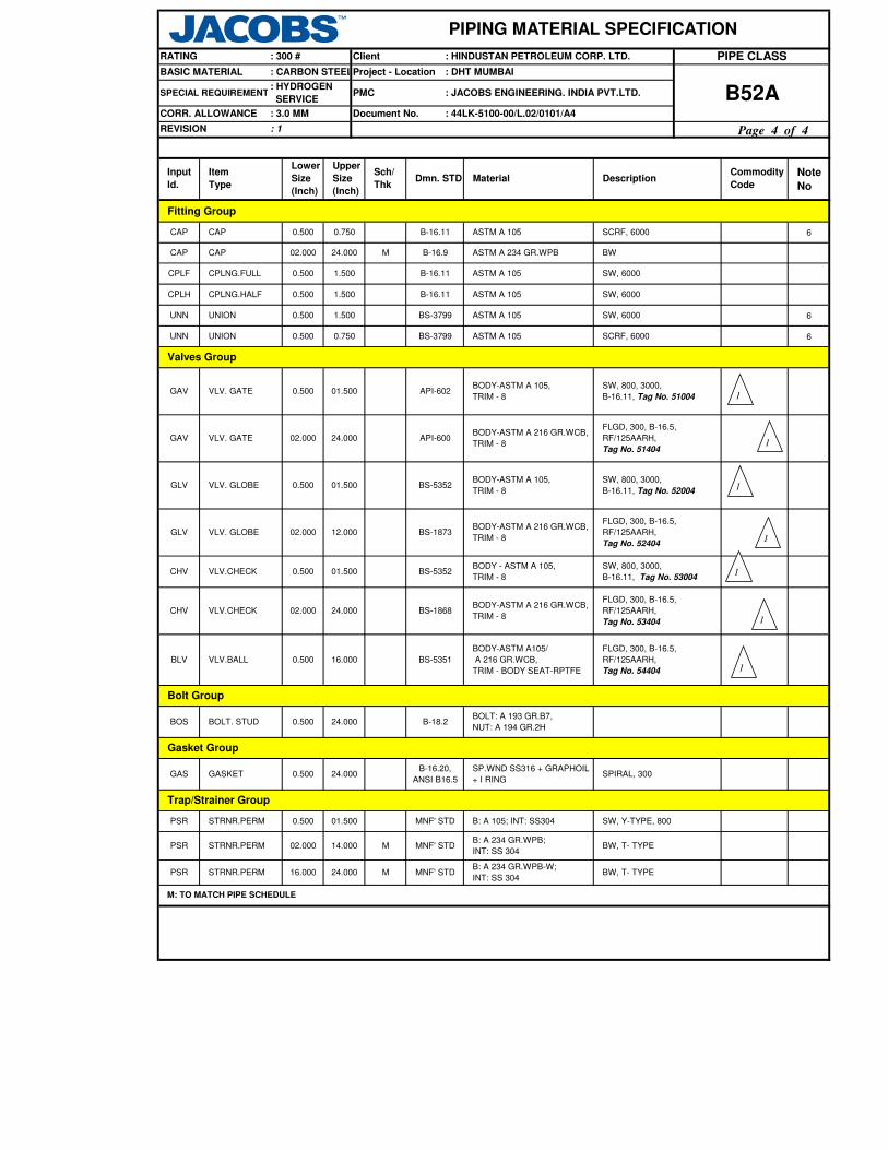
Note
No
PIPING MATERIAL SPECIFICATION
B52A
: HINDUSTAN PETROLEUM CORP. LTD.
: DHT MUMBAI
: JACOBS ENGINEERING. INDIA PVT.LTD.
: 44LK-5100-00/L.02/0101/A4
PIPE CLASSClient
CORR. ALLOWANCE : 3.0 MM
Dmn. STD
REVISION : 1
Document No.
Sch/
Thk
Item
Type
Lower
Size
(Inch)
Upper
Size
(Inch)
: CARBON STEELBASIC MATERIAL
DescriptionCommodity
CodeMaterial
Project - Location
SPECIAL REQUIREMENT: HYDROGEN
SERVICEPMC
Input
Id.
Pipe Group
RATING : 300 #
6
6
6
API-600BODY-ASTM A 216 GR.WCB,
TRIM - 8
FLGD, 300, B-16.5,
RF/125AARH,
Tag No. 51404
VLV. GATE 02.000 24.000GAV
0.500 01.500
0.750 B-16.11 ASTM A 105 SCRF, 6000
Trap/Strainer Group
B-16.20,
ANSI B16.5
SP.WND SS316 + GRAPHOIL
+ I RINGSPIRAL, 300GAS GASKET 0.500 24.000
PSR STRNR.PERM 0.500 01.500
24.000
PSR STRNR.PERM 02.000 14.000 M MNF' STDB: A 234 GR.WPB;
INT: SS 304BW, T- TYPE
M MNF' STDB: A 234 GR.WPB-W;
INT: SS 304BW, T- TYPE
MNF' STD B: A 105; INT: SS304 SW, Y-TYPE, 800
CPLF CPLNG.FULL 0.500 1.500 B-16.11 ASTM A 105 SW, 6000
Fitting Group
CPLH CPLNG.HALF 0.500 1.500 B-16.11 ASTM A 105 SW, 6000
ASTM A 105 SW, 6000
SCRF, 6000
BS-3799
Valves Group
UNN UNION 0.500 0.750 BS-3799 ASTM A 105
BODY-ASTM A 105,
TRIM - 8
SW, 800, 3000,
B-16.11, Tag No. 51004GAV VLV. GATE 0.500 01.500
GLV VLV. GLOBE BS-5352BODY-ASTM A 105,
TRIM - 8
SW, 800, 3000,
B-16.11, Tag No. 52004
API-602
GLV VLV. GLOBE 02.000 12.000 BS-1873BODY-ASTM A 216 GR.WCB,
TRIM - 8
FLGD, 300, B-16.5,
RF/125AARH,
Tag No. 52404
CHV VLV.CHECK 0.500 01.500 BS-5352BODY - ASTM A 105,
TRIM - 8
SW, 800, 3000,
B-16.11, Tag No. 53004
CHV VLV.CHECK 02.000 24.000 BS-1868BODY-ASTM A 216 GR.WCB,
TRIM - 8
FLGD, 300, B-16.5,
RF/125AARH,
Tag No. 53404
BLV VLV.BALL 0.500 16.000 BS-5351
BODY-ASTM A105/
A 216 GR.WCB,
TRIM - BODY SEAT-RPTFE
FLGD, 300, B-16.5,
RF/125AARH,
Tag No. 54404
Bolt Group
24.000 B-18.2BOLT: A 193 GR.B7,
NUT: A 194 GR.2H
M: TO MATCH PIPE SCHEDULE
Gasket Group
BOS BOLT. STUD
PSR STRNR.PERM 16.000
0.500
UNN UNION 0.500 1.500
CAP CAP 02.000 24.000
CAP CAP 0.500
M B-16.9 ASTM A 234 GR.WPB BW
1
1
1
1
1
1
1
Page 4 of 4

SW NIPPLE WITH VALVE TO SPEC. AS PER 44LK-5100-0354
REFER JACOBS STD. 44LK-5100-0350, DF3.
BUTT WELDED
REFER JACOBS STD. 44LK-5100-0350, VF3.
AS PER P& ID OR 0.75". REFER JACOBS STD. 44LK-5100-0351, V4.
FLANGED, REFER JACOBS STD. 44LK-5100-0353.
TEMP
AS PER P& ID OR 0.75". REFER JACOBS STD. 44LK-5100-0351, D4.
SERVICE
93.0 316.0260.0
58.00
SW COUPLNG
104.05
0.0
92.45104.05
204.0
94.91 89.29
NOTES
PIPE JOINTS 1.5" AND BELOW
MAINT. JOINTS FLANGED, TO BE KEPT MINIMUMALL
76.98
A. CODEDESCRIPTION
SPECIAL NOTES
SIZE
PRESS
STEAM(IBR), BOILER FEED WATER(IBR), VERY HIGH PRESSURE STEAM SUPPLY
ITEM
75.58 74.8784.36 71.01
ON LINES >= 2"
0.75"
TEMP. CONN. 1.5"
PRESS. CONN.
VENTS ON LINES <=1.5"
ON LINES >= 2"
ON LINES <=1.5"DRAINS
2" AND ABOVE
: 2
TEMPERATURE ( Deg. C ) AND PRESSURE ( Kg/Sq. cm g ) RATINGS
38.0 399.0
REVISION
371.0149.0 427.0343.0
Project - Location
PIPING MATERIAL SPECIFICATION
ClientRATING : 600 #
BASIC MATERIAL : CARBON STEEL
CORR. ALLOWANCE
PMC
Document No.: 1.5 MM
SPECIAL REQUIREMENT : IBR SERVICE : JACOBS ENGINEERING. INDIA PVT. LTD.
: 44LK-5100-00/L.02/0101/A4
PIPE CLASS
D2A
Page 1 of 4
: DHT MUMBAI
: HINDUSTAN PETROLEUM CORP. LTD.
6 . NON DESTRUCTIVE EXAMINATION REQUIREMENT FOR CARBON STEEL PIPING CLASSES SHALL BE STRINGENT OF
JACOBS STANDARD 44LK-5100-00/L.02/0103/A4 & LICENSOR'S REQUIREMENT.
4 . ALL PIPES, FITTINGS, VALVES, FLANGES, TRAPS AND STRAINERS SHALL BE TESTED AND TEST CERTIFIED IN FORM III A FOR PIPES
AND FORM III C FOR OTHERS SHALL BE REQUIRED DULY COUNTERSIGNED BY IBR AUTHORITY OR ITS APPROVED REPRESENTATIVE.
1 . NDT REQUIREMENT SHALL BE AS PER JACOBS STANDARD 44LK-5100-00/L.02/0103/A4.
7 . ASBESTOS FREE GASKETS AND STEM PACKING SHALL BE USED FOR VALVES.
MOREOVER, FOR FLANGES THE SULPHUR AND PHOSPHORUS SHALL BE LIMITED TO 0.05% EACH.
2 . USE PIPE OF CLASS 22 INSTEAD OF CLASS 12 IF PIPE THICKNESS EXCEEDS 19.05 MM.
3 . FOR STRAINERS AND SPACER & BLINDS,REFER JACOBS STANDARD DRAWINGS.
5 . CARBON CONTENT SHALL NOT EXCEED 0.25% FOR ALL PIPES, FITTINGS,FLANGES ETC. THAT MAY REQUIRE WELDING.
2

BRANCH CONNECTIONS
T 24T R 22
T R R 20T R R R 18
T R R R R 16T R R R R R 14
T R R R R R R 12T R R R R R R R 10
T R R R R R R R R 8T R R R R R R R R R 6
5T R R R R R R R R R R 4
3½T R R R R R R R R R R R 3
2½T R R R R R R R R R R R R 2
T T H H H H H H H H H H H H 1½1¼
T T H H H H H H H H H H H H H 1T T T H H H H H H H H H H H H H ¾
T T T T H H H H H H H H H H H H H ½¼
¼ ½ ¾ 1 1¼
1½ 2 2½ 3 3½ 4 5 6 8 10
12
14
16
18
20
22
24
Project - Location
Client
Document No. : 44LK-5100-00/L.02/0101/A4
PMC
SWEEPOLET
TEES
H. COUPLING
J
S SOCKOLETS
THREADOLET
L
REVISION : 2
BASIC MATERIAL : CARBON STEEL
SPECIAL REQUIREMENT
CORR. ALLOWANCE : 1.5 MM
: IBR SERVICE
BR
AN
CH
PIP
E N
B
RUN PIPE NB
W WELDOLETS
F
H
SADDLE FUSED JT T
R
INSTRUMENT TEE
REFER NOTES
CODE DESCRIPTION
REINFORCED X
P IPIPE TO PIPE
PIPING MATERIAL SPECIFICATION
RATING : 600 # PIPE CLASS: HINDUSTAN PETROLEUM CORP. LTD.
Page 2 of 4
D2A: JACOBS ENGINEERING. INDIA PVT. LTD.
: DHT MUMBAI

Note
No
2
PMC
Project - Location
Client
: 44LK-5100-00/L.02/0101/A4Document No.
: JACOBS ENGINEERING. INDIA PVT. LTD.
: DHT MUMBAI
D2A
Fitting Group
B-16.11 ASTM A 105
SWGC SWAGE.CONC 0.500
REDE REDUC.ECC 02.000
REDE REDUC.ECC 16.000
REDC REDUC.CONC 02.000
ELB45 ELBOW.45 0.500
ELB45 ELBOW.45 02.000
TRED
01.500
ELB90 ELBOW. 90 02.000 14.000
ELB90
B-16.11 ASTM A 105 SW, 3000
M B-16.9 ASTM A 234 GR.WPB
M
PIP
PIPE
PIPE
BW, 1.5D
PIPE 16.000PIP
ASTM A 105B-16.11
BE, SEAMLESS
ASTM A 672 GR.B60 CL.12
10.000PIP
24.000 S60 B-36.10 BE, E.F.S.W.
PIP PIPE
XS B-36.10
12.000 ASTM A 106 GR.BB-36.10
ASTM A 106 GR.B
: 1.5 MM
Dmn. STD
REVISION : 2
Item
Type
: IBR SERVICE
PIP 0.500 01.500
Input Id.
Pipe Group
ASTM A 106 GR.BPIPE
Description
CORR. ALLOWANCE
Commodity
Code
XS
Sch/
ThkMaterial
B-36.10 PE, SEAMLESSXS
BE, SEAMLESS
FLB FLNG.BLIND
01.500
: CARBON STEELBASIC MATERIAL
Lower
Size
(Inch)
Upper
Size
(Inch)
02.000 08.000
SPECIAL REQUIREMENT
24.000
Flange Group
FLG
ELB90 ELBOW. 90 0.500
MFLNG. SW 0.5000 01.500
NIP NIPPLE 0.500 M01.500 ASTM A 106 GR.B PBE, SEAMLESSB-36.10
FLNG. WN 02.000 24.000 M B-16.5 ASTM A 105
600, RF/125AARH
ASTM A 105B-16.5
B-16.5 ASTM A 105
600, RF/125AARH
600, RF/125AARH
ASME
B-16.48ASTM A 105 600, FF/125AARH
FLG
FEF FLNG.FIG.8 0.500 08.000
0.500
FEF SPCR&BLND 10.000 24.000ASME
B-16.48ASTM A 105 600, FF/125AARH
14.000 M B-16.9 ASTM A 234 GR.WPB BW, 1.5D
TEQ T.EQUAL 0.500 01.500 B-16.11 ASTM A 105 SW, 3000
TEQ T.EQUAL 02.000 14.000 M B-16.9 ASTM A 234 GR.WPB BW
T.RED 0.500 01.500 B-16.11 ASTM A 105 SW,3000
TRED T.RED 02.000 14.000 M, M B-16.9 ASTM A 234 GR.WPB BW
14.000 ASTM A 234 GR.WPBM, M B-16.9
B-16.9
BW
14.000
M, M
M, M
M, M24.000
BS-3799
BS-3799 ASTM A 105 PBE03.000
CPLF
B-16.924.00002.000
B-16.11CPLNG.FULL 0.500 01.500
03.000
CAP CAP
M, M
M
SWGE SWAGE.ECC 0.500
PIPING MATERIAL SPECIFICATION
RATING : 600 # : HINDUSTAN PETROLEUM CORP. LTD. PIPE CLASS
ASTM A 105 PBE
BW
ASTM A 105
SW, 3000
ASTM A 234 GR.WPB BW
ASTM A 234 GR.WPB
SW, 3000
SW, 3000CPLH CPLNG.HALF 0.500 01.500
M: TO MATCH PIPE SCHEDULE
ELBOW. 90 16.000 24.000
TEQ T.EQUAL 16.000 24.000
B-16.9 ASTM A 234 GR.WPB-W BW, 1.5D
ELB45 ELBOW.45 16.000 24.000 M B-16.9 ASTM A 234 GR.WPB-W BW, 1.5D
M B-16.9 ASTM A 234 GR.WPB-W BW
TRED T.RED 16.000 24.000 M, M B-16.9 ASTM A 234 GR.WPB-W BW
REDC REDUC.CONC 16.000 24.000 M, M B-16.9 ASTM A 234 GR.WPB-W BW
B-16.9 ASTM A 234 GR.WPB-W BW
ASTM A 106 GR.B BE, SEAMLESS14.000 14.000 S60 B-36.10 2
2
2
2
2
Page 3 of 4

Note
No
PMC
Project - Location
Client
: 44LK-5100-00/L.02/0101/A4Document No.
: JACOBS ENGINEERING. INDIA PVT. LTD.
: DHT MUMBAI
D2A: 1.5 MM
Dmn. STD
REVISION : 2
Item
Type
: IBR SERVICE
Input Id.
Pipe Group
Description
CORR. ALLOWANCE
Commodity
Code
Sch/
ThkMaterial
: CARBON STEELBASIC MATERIAL
Lower
Size
(Inch)
Upper
Size
(Inch)
SPECIAL REQUIREMENT
PIPING MATERIAL SPECIFICATION
RATING : 600 # : HINDUSTAN PETROLEUM CORP. LTD. PIPE CLASS
FLGD, 600, B-16.5,
RF/125AARH, Tag
No.53502
G3V VLV.PISTON 0.500 01.500 MNF' STDBODY- ASTM A 105,
TRIM- 13% CR STEEL
SW, 800, 3000,
B-16.11, Tag
No.64002
CHV VLV.CHECK 02.000 24.000
SW, Y-TYPE, 800
SP.WND SS 316+ GRAFIL
SW, 800, 3000,
B-16.11, Tag No.
51002
PSR STRNR.PERM 0.500 B : A 105; INT : SS304MNF' STD01.500
API-600
API-602
BS-1868
Valves Group
VLV.CHECK 0.500 01.500
0.500 01.500
BS-5352BODY-ASTM A 105,
TRIM-8
SW, 800, 3000,
B-16.11, Tag
No.52002
FLGD, THRMDNMC,
600, RF/125 AARHTRP TRAP..STEAM 0.500 1.500 MNF' STD
B : A 105;
T: 13% CR; SS 304
G3V
FLGD, 600, B-16.5,
RF/125AARH, Tag
No.51502
GAV VLV. GATE 02.000 24.000
SW, 800, 3000,
B-16.11, Tag
No.53002
GLV
GLV VLV. GLOBE 0.500 01.500
VLV. GLOBE 02.000 12.000
B : A 516 GR.70; INT: SS304CONE TYPE,
600, FF / 125 AARH
BODY-ASTM A 105,
TRIM-8
STUD : A 193 GR.B7,
NUT : A 194 GR.2H
Bolt Group
CHV
VLV.PISTON
BODY-ASTM A 216 GR.WCB,
TRIM-8
FLGD, 600, B-16.5,
RF/125AARH, Tag
No.52502
BS-1873
08.000 MNF' STDBODY- ASTM A 216 GR.WCB,
TRIM- 13% CR STEEL
BS-5352
BODY- ASTM A 216 GR.WCB,
TRIM-8
M: TO MATCH PIPE SCHEDULE
Gasket Group
BOS BOLT.STUD B-18.2
PSR STRNR.PERM MNF' STD
0.500 24.000
24.000
MNF' STD
B-16.20,
ANSI B16.524.000
02.000
B : A 216 GR.WCB;
INT : SS304
FLGD, Y-TYPE,
600, RF/125 AARH
FLGD, 600, B-16.5,
RF/125AARH, Tag
No.64502
SPIRAL, 600
Trap/Strainer Group
02.000
BODY-ASTM A 105,
TRIM-8
BODY-ASTM A 216 GR.WCB,
TRIM-8
GAV VLV. GATE
0.500
TSR STRNR.TEMP 01.500 24.000
GAS GASKET
2
2
2
2
2
2
2
2
Page 4 of 4

AS PER P&ID OR 0.75". REFER JACOB'S STD. 44LK-5100-0351, D3
SCREWED COUPLING
REFER JACOB'S STD. 44LK-5100-0350, DC3
FLANGED (SCREWED) TO BE KEPT MINIMUM
SIZE
1.5" & BELOWMAINTAINENCE
JOINTS
REFER JACOB'S STD. 44LK-5100-0350, VC3
SCRD NIPPLE WITH VALVE TO SPEC AS PER JACOB'S STD. 44LK-5100-0354
AS PER P&ID OR 0.75". REFER JACOB'S STD. 44LK-5100-0351,V3
FLANGED, REFER JACOB'S STD. 44LK-5100-0353
0.0
PRESS 10.55
TEMP
SPECIAL NOTES
UNIONS (SCRF) TO BE KEPT MINIMUM
A. CODEDESCRIPTIONITEM
10.55
1. NDT REQUIREMENT SHALL BE AS PER JACOBS STANDARD 44LK-5100-00/L.02/0103/A4.
SERVICE
3. SURFACES WHERE GALVANISING HAS BEEN BURNT OFF SHALL BE WIRE BRUSHED AND COLD GALVANISED
10.55
65.0
POTABLE WATER (ABOVE GROUND), FIRE WATER-SPRINKLER SYSTEM AFTER ORIFICE, POTABLE
ON LINES ≥ 2"
0.75"
TEMP. CONN. 1.5"
PRESS. CONN.
VENTS ON LINES ≤ 1.5"
ON LINES ≥ 2"
ON LINES ≤ 1.5" DRAINS
2" AND ABOVE
PIPE JOINTS UP TO 6"
: 2
TEMPERATURE ( Deg. C ) AND PRESSURE ( Kg/Sq. cm g ) RATINGS
38.0
REVISION
Project - Location
PIPING MATERIAL SPECIFICATION
ClientRATING : 150 #
BASIC MATERIAL : CS (GALV.)
PIPE CLASS: HINDUSTAN PETROLEUM CORP. LTD.
CORR. ALLOWANCE
PMC
Document No.: 0.0 MM
SPECIAL REQUIREMENT : - : JACOBS ENGINEERING. INDIA PVT. LTD.
: 44LK-5100-00/L.02/0101/A4J2A
Page 1 of 4
: DHT MUMBAI
WATER UNDER GROUND (REFER NOTE 130)
6. FOR USE BELOW GROUND LEVEL, PIPE THICKNESS TO BE VERIFIED.
2. THREADED JOINTS SHALL BE MADE WITH 1" WIDTH PTFE JOINING TAPE.
NOTES
5. ASBESTOS FREE GASKETS AND STEM PACKING SHALL BE USED FOR VALVES.
WITH ZINC COATING COMPOUND.
4. NON DESTRUCTIVE EXAMINATION REQUIREMENT FOR CARBON STEEL PIPING CLASSES SHALL BE STRINGENT OF
JACOBS STANDARD 44LK-5100-00/L.02/0103/A4 & LICENSOR'S REQUIREMENT.

T 6
5
T T 4
3½
T T T 3
2½
T T T T 2
T T T T T 1½
1¼
T T T T T T 1
T T T T T T T ¾
T T T T T T T T ½
¼
¼ ½ ¾ 1 1¼
1½ 2 2½ 3 3½ 4 5 6
INSTRUMENT TEE
PIPING MATERIAL SPECIFICATION
ClientRATING : 150 # PIPE CLASS: HINDUSTAN PETROLEUM CORP. LTD.
F
PIPE TO PIPE
TEES
THREADOLET
R REINFORCED X
P I
W
T
H. COUPLINGH
SADDLE FUSED JT
CODE DESCRIPTION
PMC
Document No.
BRANCH CONNECTIONS
: 44LK-5100-00/L.02/0101/A4J2A
Page 2 of 4
: DHT MUMBAI
: JACOBS ENGINEERING. INDIA PVT. LTD.
Project - Location
REVISION : 2
BASIC MATERIAL : CS (Galv.)
SPECIAL REQUIREMENT
CORR. ALLOWANCE : 0 MM
: -
BR
AN
CH
PIP
E N
B
RUN PIPE NB
J
S SOCKOLETS L SWEEPOLET
WELDOLETS
Refer Notes

Note
No
SCRF, 3000
150, RF/125AARH
B-16.11 ASTM A 105 (GALV)
Project - Location
J2A
PIPE CLASS: HINDUSTAN PETROLEUM CORP. LTD.
: DHT MUMBAI
: JACOBS ENGINEERING. INDIA PVT. LTD.
: 44LK-5100-00/L.02/0101/A4
PMC
PIPING MATERIAL SPECIFICATION
ClientRATING : 150 #
CHV VLV.CHECK 0.500 01.500 IS:778 CL.2
BODY-IS 318 GR.2 LEADED
TIN BRONZE,
TRIM-IS 320 ALLOY HT2
SCRF,CL.2,3000,
B-1.20.1, Tag No.
53080
M: TO MATCH PIPE SCHEDULE
GLV VLV. GLOBE 02.000 BS-1873BODY-ASTM A 351 GR.CF8,
TRIM- SS304, STELLITED
FLGD, 150, B-16.5,
RF/125AARH, Tag
No.52345
16.000
GLV VLV. GLOBE IS:778 CL.2
BODY-IS 318 GR.2 LEADED
TIN BRONZE,
TRIM-IS 320 ALLOY HT2
SCRF,CL.2,3000,
B-1.20.1, Tag No.
52080
IS:778 CL.2
SCRF,CL.2,3000,
B-1.20.1, Tag No.
51080
GAV VLV. GATE 0.500 01.500
BODY-IS 318 GR.2 LEADED
TIN BRONZE,
TRIM-IS 320 ALLOY HT2
B-16.11 ASTM A 105 (GALV) SCRF,3000CPLH CPLNG.HALF 0.500 01.500
B-16.11 ASTM A 105 (GALV) SCRF,3000CPLF CPLNG.FULL 0.500 01.500
M, M BS-3799 ASTM A 105 (GALV) TBESWGE SWAGE.ECC 0.500 03.000
BS-3799 ASTM A 105 (GALV) TBESWGC SWAGE.CONC 0.500 03.000
CAP CAP 02.000 06.000 IS-1239-II IS-1239(PART-II) (GALV) SCRF,NA
01.500
T.RED 02.000 06.000 IS-1239-II SCRF,NA
B-16.11
TRED
TEQ T.EQUAL 02.000
TRED T.RED 0.500
SCRF,NA
SCRF, 3000B-16.11 ASTM A 105 (GALV)T.EQUAL 0.500 01.500
06.000
Flange Group
FLG FLNG.SCRD
FEF FLNG.FIG.8
FLB FLNG.BLIND
ASME
B-16.48150, FF/125AARH
0.500
0.500 06.000
06.000
0.500 06.000 150, RF/125AARHB-16.5 ASTM A 105 (GALV)
Sch/
ThkMaterial
IS-1239-I SCRM,WELDEDPIPE HVY
Lower
Size
(Inch)
Upper
Size
(Inch)
Fitting Group
ELB90
Commodity
Code
: CS (Galv.)BASIC MATERIAL
PIP 0.500 06.000
Input
Id.
Pipe Group
IS-1239(GALV)
SPECIAL REQUIREMENT : -
CORR. ALLOWANCE : 0 MM
Dmn. STD
REVISION : 2
Document No.
DescriptionItem
Type
TEQ
UNN UNION 0.500 01.500 IS-1239-II ASTM A 105 (GALV) SCRF,3000
IS-1239(PART-II) (GALV)
SCRF,NA
Fitting Group
SCRF, 3000ASTM A 105 (GALV)
ELB45 ELBOW.45 02.000 06.000
06.000
01.500ELBOW. 90 0.500
SCRF,NA
ELB45 ELBOW.45 0.500 01.500 SCRF, 3000
ELB90 ELBOW. 90 02.000
0.500 01.500
Valves Group
API-600
B-16.11 ASTM A 105 (GALV)
IS-1239-II IS-1239(PART-II) (GALV)
UNN UNION 02.000 06.000
GAV VLV. GATE 02.000 24.000
IS-1239(PART-II) (GALV)
B-16.5 ASTM A 105 (GALV)
M, M
ASTM A 105 (GALV)
IS-1239-II IS-1239(PART-II) (GALV)
B-16.11
IS-1239-II
SCRF,3000
BODY-ASTM A 351 GR.CF8,
TRIM- SS304, STELLITED
FLGD, 150, B-16.5,
RF/125AARH, Tag
No. 51345
IS-1239-II IS-1239(PART-II) (GALV) SCRF,NA
ASTM A 105 (GALV)CAP CAP 0.500 01.500
2
2
2
2
2
Page 3 of 4

Note
No
Project - Location
J2A
PIPE CLASS: HINDUSTAN PETROLEUM CORP. LTD.
: DHT MUMBAI
: JACOBS ENGINEERING. INDIA PVT. LTD.
: 44LK-5100-00/L.02/0101/A4
PMC
PIPING MATERIAL SPECIFICATION
ClientRATING : 150 #
Sch/
ThkMaterial
Lower
Size
(Inch)
Upper
Size
(Inch)
Commodity
Code
: CS (Galv.)BASIC MATERIAL
Input
Id.
SPECIAL REQUIREMENT : -
CORR. ALLOWANCE : 0 MM
Dmn. STD
REVISION : 2
Document No.
DescriptionItem
Type
M: TO MATCH PIPE SCHEDULE
Gasket Group
BOS BOLT. STUD 0.500 06.000 B-18.2BOLT:A193 GR.B7,
NUT:A194 GR.2H
Bolt Group
BS-1868BODY-ASTM A 351GR.CF8,
TRIM- SS304
FLGD, 150, B-16.5,
RF/125AARH, Tag
No. 53345
CHV VLV.CHECK 02.000 24.000
Valves Group
GAS GASKET 0.500 06.000B-16.21,
ANSI B16.5
GRAPHITE WITH SS316
TANGED INSRING, 150, 2 MM
2
Page 4 of 4

FLANGED, REFER JACOB'S STD. 44LK-5100-0353
SCRD NIPPLE WITH VALVE TO SPEC AS PER JACOB'S STD. 44LK-5100-0354
TEMP. CONN.
PRESS. CONN.
1.5"
0.75"
NOTES
5. ASBESTOS FREE GASKETS AND STEM PACKING SHALL BE USED FOR VALVES.
6. FOR SIZE RANGE 4" TO 6", REFER PIPING SPECIFICATION J3A.
4. NON DESTRUCTIVE EXAMINATION REQUIREMENT FOR CARBON STEEL PIPING CLASSES SHALL BE STRINGENT OF
JACOBS STANDARD 44LK-5100-00/L.02/0103/A4 & LICENSOR'S REQUIREMENT.
2. THREADED JOINTS SHALL BE MADE WITH 1" WIDTH PTFE JOINING TAPE.
: 0 MM
SPECIAL REQUIREMENT : - : JACOBS ENGINEERING. INDIA PVT. LTD.
: 44LK-5100-00/L.02/0101/A4J1M
Page 1 of 4
: HINDUSTAN PETROLEUM CORP. LTD.
CORR. ALLOWANCE
PMC
Document No.
: DHT MUMBAIProject - Location
PIPING MATERIAL SPECIFICATION
ClientRATING : 150 #
BASIC MATERIAL : SS 316
PIPE CLASS
PIPE JOINTS
2" AND ABOVE
: 1
TEMPERATURE ( Deg. C ) AND PRESSURE ( Kg/Sq. cm g ) RATINGS
65.0
REVISION
ON LINES ≤ 1.5"
ON LINES ≥ 2"
ON LINES ≥ 2"
VENTS
DRAINS ON LINES ≤ 1.5"
UP TO 3"
1. NDT REQUIREMENT SHALL BE AS PER JACOBS STANDARD 44LK-5100-00/L.02/0103/A4.
10.55
INSTRUMENT AIR FROM INSTRUMENT AIR DRYER TO CONSUMERS, INSTRUMENT AIR FROM EXISTING HEADER TO
AIR COMPRESSOR START-UP
0.0
PRESS 10.55
TEMP
SERVICE
ITEM
UNIONS (SCRF) TO BE KEPT MINIMUM
A. CODEDESCRIPTION
AS PER P&ID OR 0.75". REFER JACOB'S STD. 44LK-5100-0351,V3
AS PER P&ID OR 0.75". REFER JACOB'S STD. 44LK-5100-0351, D3
SPECIAL NOTES
SIZE
1.5" & BELOWMAINTAINENCE
JOINTS
FLANGED (SCREWED) TO BE KEPT MINIMUM
SCREWED COUPLING
REFER JACOB'S STD. 44LK-5100-0350, DC3
REFER JACOB'S STD. 44LK-5100-0350, VC3
3. NO FIELD HYDROSTATIC TESTING IS PERMITTED IN INSTRUMENT AIR SERVICE.
1

6
5
4
3½
T 3
2½
T T 2
T T T 1½
1¼
T T T T 1
T T T T T ¾
T T T T T T ½
¼
¼ ½ ¾ 1 1¼
1½ 2 2½ 3 3½ 4 5 6
BR
AN
CH
PIP
E N
B
RUN PIPE NB
J
S SOCKOLETS L SWEEPOLET
WELDOLETS
Refer Notes
Project - Location
REVISION : 1
BASIC MATERIAL : SS 316
SPECIAL REQUIREMENT
CORR. ALLOWANCE : 0 MM
: - PMC
Document No.
BRANCH CONNECTIONS
: 44LK-5100-00/L.02/0101/A4J1M
Page 2 of 4
: DHT MUMBAI
: JACOBS ENGINEERING. INDIA PVT. LTD.
CODE DESCRIPTION
T
H. COUPLINGH
SADDLE FUSED JT
THREADOLET
R REINFORCED X
P I
W
INSTRUMENT TEE
PIPING MATERIAL SPECIFICATION
ClientRATING : 150 # PIPE CLASS: HINDUSTAN PETROLEUM CORP. LTD.
F
PIPE TO PIPE
TEES

Note
No
CAP CAP 0.500 01.500 SCRF,3000
BODY-ASTM A 351 GR. CF8M,
TRIM- SS 316
FLGD, 150, B-16.5,
RF/125AARH,
Tag No. 51361
BS-3799 ASTM A 182 Gr.F316 SCRF,3000UNION 0.500 01.500
03.000
B-16.5 ASTM A 182 Gr.F316
ASTM A 403
GR. WP316-S
B-16.11
03.000
ASTM A 182 Gr.F316B-16.11
Valves Group
ASTM A 182 Gr.F316
B-16.11 ASTM A 182 Gr.F316
01.500
GAV VLV. GATE 02.000
Fitting Group
UNN
01.500
API-600
01.500ELBOW. 90 0.500
B-16.9ELBOW. 90 02.000
SCRF, 3000ASTM A 182 Gr.F316ELB90
ELB45 ELBOW.45 02.000
ELB45 ELBOW.45 0.500
ELB90
CORR. ALLOWANCE : 0 MM
Dmn. STD
REVISION : 1
Document No.
Description
: SS 316BASIC MATERIAL
PIP 0.500 03.000
Input
Id.
Pipe Group
ASTM A 312 TP316, SEAMLESS
SPECIAL REQUIREMENT : -
PIPE 80S
Lower
Size
(Inch)
Upper
Size
(Inch)
Item
Type
Commodity
Code
Sch/
ThkMaterial
B - 36.19 SCRM
0.500 03.000 150, RF/125AARHB-16.5 ASTM A 182 Gr.F316
0.500
0.500 03.000
03.000
Flange Group
FLG FLNG.SCRD
FEF FLNG.FIG.8
FLB FLNG.BLIND
ASME
B-16.48150, FF/125AARH
SCRF,NA
SCRF, 3000B-16.11 ASTM A 182 Gr.F316
B-16.9ASTM A 403
GR. WP316-S 03.000
TRED
TEQ T.EQUAL 02.000
TRED T.RED 0.500
T.RED 02.000
03.000
M, M
B-16.9 SCRF,NAASTM A 403
GR. WP316-S
01.500
03.000
BS-3799SWGC SWAGE.CONC 0.500 01.500 TBE
SWGE SWAGE.ECC 0.500 01.500 M, M BS-3799 ASTM A 182 Gr.F316 TBE
CPLF CPLNG.FULL 0.500 01.500 B-16.11 ASTM A 182 Gr.F316 SCRF,3000
CPLH CPLNG.HALF 0.500 01.500
CPLNG.HALF 02.000 03.000
M: TO MATCH PIPE SCHEDULE
GAV VLV. GATE 0.500 01.500
CPLH
BODY-ASTM A 182 Gr.F316,
TRIM- SS 316 STELLITED
SCRF,800, B-1.20.1,
Tag No. 52091
API-602SCRF,800, B-1.20.1,
Tag No. 51091
BODY-ASTM A 182 Gr.F316,
TRIM- SS 316 STELLITED
GLV VLV. GLOBE BS-53520.500 01.500
PIPING MATERIAL SPECIFICATION
ClientRATING : 150 #
Project - Location
J1M
PIPE CLASS: HINDUSTAN PETROLEUM CORP. LTD.
: DHT MUMBAI
: JACOBS ENGINEERING. INDIA PVT. LTD.
: 44LK-5100-00/L.02/0101/A4
PMC
SCRF,NAB-16.9ASTM A 403
GR. WP316-S
SCRF,NA
SCRF, 3000B-16.11 ASTM A 182 Gr.F316
150, RF/125AARH
ASTM A 182 Gr.F316
Fitting Group
TEQ T.EQUAL 0.500
NIP NIPPLE 0.500 01.500 M, M B - 36.19 ASTM A 312 TP316, SEAMLESS PBE
B-16.11ASTM A 403
GR. WP316-S SCRF,3000CPLF CPLNG.FULL 02.000 03.000
B-16.11ASTM A 403
GR. WP316-S SCRF,3000
SCRF, 3000
B-16.11 ASTM A 182 Gr.F316 SCRF,3000
1
1
1
Page 3 of 4

Note
No
CORR. ALLOWANCE : 0 MM
Dmn. STD
REVISION : 1
Document No.
Description
: SS 316BASIC MATERIAL
Input
Id.
SPECIAL REQUIREMENT : -
Lower
Size
(Inch)
Upper
Size
(Inch)
Item
Type
Commodity
Code
Sch/
ThkMaterial
PIPING MATERIAL SPECIFICATION
ClientRATING : 150 #
Project - Location
J1M
PIPE CLASS: HINDUSTAN PETROLEUM CORP. LTD.
: DHT MUMBAI
: JACOBS ENGINEERING. INDIA PVT. LTD.
: 44LK-5100-00/L.02/0101/A4
PMC
GAS GASKET 0.500 06.000B-16.21,
ANSI B16.5
GRAPHITE WITH SS316
TANGED INSRING, 150, 2 MM
Valves Group
GLV VLV. GLOBE 02.000 03.000 BS-1873BODY-ASTM A 351 GR. CF8M,
TRIM- SS 316
FLGD, 150, B-16.5,
RF/125AARH,
Tag No. 52361
03.000
CHV VLV.CHECK 0.500 01.500 BS-5352BODY-ASTM A 182 Gr.F316,
TRIM- SS 316 STELLITED
SCRF,800, B-1.20.1,
Tag No. 53091
BOLT:A193 GR.B7,
NUT:A194 GR.2H
Bolt Group
BS-1868BODY-ASTM A 351 GR. CF8M,
TRIM- SS 316
FLGD, 150, B-16.5,
RF/125AARH,
Tag No. 53361
CHV VLV.CHECK 02.000
M: TO MATCH PIPE SCHEDULE
Gasket Group
BOS BOLT. STUD 0.500 06.000 B-18.2
1
1
1
Page 4 of 4

SCREWED COUPLING
AS PER P&ID OR 0.75". REFER JACOB'S STD. 44LK-5100-0351, D3
AS PER P&ID OR 0.75". REFER JACOB'S STD. 44LK-5100-0351,V3
J3A
Page 1 of 3
NOTES
6. ASBESTOS FREE GASKETS AND STEM PACKING SHALL BE USED FOR VALVES.
7. FOR SIZE RANGE 1/2" TO 3", REFER PIPING SPECIFICATION J1M.
WITH ZINC COATING COMPOUND.
5. NON DESTRUCTIVE EXAMINATION REQUIREMENT FOR CARBON STEEL PIPING CLASSES SHALL BE STRINGENT OF
CORR. ALLOWANCE
PMC
Document No.
: DHT MUMBAI
: 0 MM
SPECIAL REQUIREMENT : - : JACOBS ENGINEERING. INDIA PVT. LTD.
: 44LK-5100-00/L.02/0101/A4
Project - Location
PIPING MATERIAL SPECIFICATION
ClientRATING : 150 #
BASIC MATERIAL : CS (GALV.)
PIPE CLASS: HINDUSTAN PETROLEUM CORP. LTD.
: 3
TEMPERATURE ( Deg. C ) AND PRESSURE ( Kg/Sq. cm g ) RATINGS
65.0
REVISION
ON LINES ≥ 4"VENTS
DRAINS ON LINES ≥ 4"
UP TO 6"PIPE JOINTS
JACOBS STANDARD 44LK-5100-00/L.02/0103/A4 & LICENSOR'S REQUIREMENT.
3. SURFACES WHERE GALVANISING HAS BEEN BURNT OFF SHALL BE WIRE BRUSHED AND COLD GALVANISED
10.55
INSTRUMENT AIR FROM INSTRUMENT AIR DRYER TO CONSUMERS
2. THREADED JOINTS SHALL BE MADE WITH 1" WIDTH PTFE JOINING TAPE.
1. NDT REQUIREMENT SHALL BE AS PER JACOBS STANDARD 44LK-5100-00/L.02/0103/A4.
0.0
PRESS 10.55
TEMP
SERVICE
SIZE
4" AND ABOVEMAINTAINENCE
JOINTS
SPECIAL NOTES
FLANGED (SCREWED) TO BE KEPT MINIMUM
A. CODEDESCRIPTIONITEM
4. NO FIELD HYDROSTATIC TESTING IS PERMITTED IN INSTRUMENT AIR SERVICE.
3
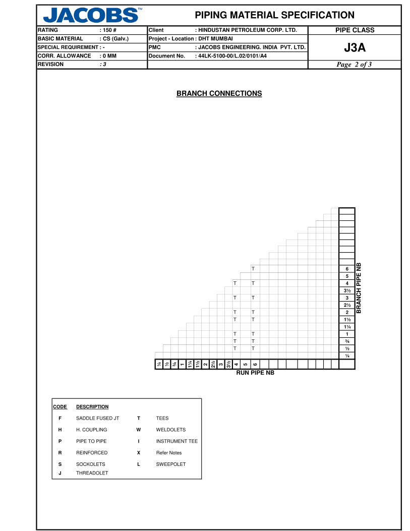
T 6
5
T T 4
3½
T T 3
2½
T T 2
T T 1½
1¼
T T 1
T T ¾
T T ½
¼
¼ ½ ¾ 1 1¼
1½ 2 2½ 3 3½ 4 5 6
BR
AN
CH
PIP
E N
B
RUN PIPE NB
J
S SOCKOLETS L SWEEPOLET
WELDOLETS
Refer Notes
Project - Location
REVISION : 3
BASIC MATERIAL : CS (Galv.)
SPECIAL REQUIREMENT
CORR. ALLOWANCE : 0 MM
: - PMC
Document No.
BRANCH CONNECTIONS
: 44LK-5100-00/L.02/0101/A4J3A
Page 2 of 3
: DHT MUMBAI
: JACOBS ENGINEERING. INDIA PVT. LTD.
CODE DESCRIPTION
T
H. COUPLINGH
SADDLE FUSED JT
THREADOLET
R REINFORCED X
P I
W
INSTRUMENT TEE
PIPING MATERIAL SPECIFICATION
ClientRATING : 150 # PIPE CLASS: HINDUSTAN PETROLEUM CORP. LTD.
F
PIPE TO PIPE
TEES

Note
No
ASTM A 234 GR. WPB
(GALV)06.000
06.000 B-16.5 ASTM A 105 (GALV)
ASME
B-16.4806.000
Fitting Group
API-60006.000
Valves Group
BODY-ASTM A 216 GR.
WCB, TRIM-8
FLGD, 150, B-16.5,
RF/125AARH,
Tag No. 51301
ELB90 04.000 B-16.9ELBOW. 90
CORR. ALLOWANCE : 0 MM
Dmn. STD
REVISION : 3
Document No.
Description
: CS (Galv.)BASIC MATERIAL
PIP 04.000 06.000
Input
Id.
Pipe Group
IS-1239(GALV)
SPECIAL REQUIREMENT : -
PIPE HVY
Lower
Size
(Inch)
Upper
Size
(Inch)
Item
Type
B-16.5 ASTM A 105 (GALV)
Commodity
Code
Sch/
ThkMaterial
IS-1239-I SCRM,WELDED
Flange Group
FLG FLNG.SCRD 04.000
150, RF/125AARH04.000
06.000 150, RF/125AARH
FEF FLNG.FIG.8
FLB FLNG.BLIND
150, FF/125AARH
ELB45 ELBOW.45 04.000 B-16.9
SCRF,NA
ASTM A 234 GR. WPB
(GALV)
04.000
06.000
06.000
TRED
TEQ T.EQUAL
04.000T.RED 06.000 B-16.9 SCRF,NAASTM A 234 GR. WPB
(GALV)
B-16.21,
ANSI B16.5
GRAPHITE WITH SS316
TANGED INSRING, 150, 2 MM
06.000
BOLT:A193 GR.B7,
NUT:A194 GR.2H
B-16.11ASTM A 234 GR. WPB
(GALV)SCRF,3000
GAS GASKET 04.000 06.000
GAV VLV. GATE 04.000
CPLH CPLNG.HALF 04.000 06.000
GLV VLV. GLOBE 04.000 06.000 BS-1873BODY-ASTM A 216 GR.
WCB, TRIM-8
FLGD, 150, B-16.5,
RF/125AARH,
Tag No. 52301
Bolt Group
BS-1868BODY-ASTM A 216 GR.
WCB, TRIM-8
FLGD, 150, B-16.5,
RF/125AARH,
Tag No. 53301
CHV VLV.CHECK 04.000
M: TO MATCH PIPE SCHEDULE
Gasket Group
BOS BOLT. STUD 04.000 06.000 B-18.2
PIPING MATERIAL SPECIFICATION
ClientRATING : 150 # PIPE CLASS: HINDUSTAN PETROLEUM CORP. LTD.
Project - Location
J3A: 44LK-5100-00/L.02/0101/A4
PMC
: DHT MUMBAI
: JACOBS ENGINEERING. INDIA PVT. LTD.
ASTM A 105 (GALV)
Fitting Group
04.000 SCRF,NAB-16.9ASTM A 234 GR. WPB
(GALV)
SCRF,NA
CPLF CPLNG.FULL 04.000 06.000
B-16.11ASTM A 234 GR. WPB
(GALV)SCRF,3000
3
3
3
Page 3 of 3

REFER JACOBS STD. 44LK-5100-0350, VF3.
SW NIPPLE WITH VALVE TO SPEC. AS PER 44LK-5100-0354
AS PER P& ID OR 0.75". REFER JACOBS STD. 44LK-5100-0351, V4.
FLANGED, REFER JACOBS STD. 44LK-5100-0353.
REFER JACOBS STD. 44LK-5100-0350, DF3.
BUTT WELDED
TEMP
AS PER P& ID OR 0.75". REFER JACOBS STD. 44LK-5100-0351, D4.
6. CORROSIVE ALLOWANCE HAS BEEN ADJUSTED TO SELECT OPTIMUM SCHEDULE REFER GENERAL NOTES TO PMS.
SERVICE
93.0 316.0260.0
28.82
SW COUPLNG
52.02 47.45 44.64
0.0
46.0552.02
204.0
STEAM(IBR), BOILER FEED WATER(IBR) & CONDENSATE ( IBR), MEDIUM PRESSURE STEAM SUPPLY
ITEM
NOTES
A. CODEDESCRIPTION
SPECIAL NOTES
SIZE
PIPE JOINTS 1.5" AND BELOW
MAINT. JOINTS FLANGED, TO BE KEPT MINIMUMALL
5. CARBON CONTENT SHALL NOT EXCEED 0.25% FOR ALL PIPES, FITTINGS,FLANGES ETC. THAT MAY REQUIRE WELDING.
38.66 37.61PRESS 37.6142.18 35.50
ON LINES >= 2"
0.75"
TEMP. CONN. 1.5"
PRESS. CONN.
VENTS ON LINES <=1.5"
ON LINES >= 2"
ON LINES <=1.5"DRAINS
2" AND ABOVE
: 2
TEMPERATURE ( Deg. C ) AND PRESSURE ( Kg/Sq. cm g ) RATINGS
38.0 399.0
REVISION
371.0149.0 427.0343.0
Project - Location
PIPING MATERIAL SPECIFICATION
ClientRATING : 300 #
BASIC MATERIAL : CARBON STEEL
CORR. ALLOWANCE
PMC
Document No.: 1.5 MM
SPECIAL REQUIREMENT : IBR SERVICE : JACOBS ENGINEERING. INDIA PVT. LTD.
: 44LK-5100-00/L.02/0101/A4
PIPE CLASS
B2A
Page 1 of 4
: DHT MUMBAI
: HINDUSTAN PETROLEUM CORP. LTD.
MOREOVER, FOR FLANGES THE SULPHUR AND PHOSPHORUS SHALL BE LIMITED TO 0.05% EACH.
7. NON DESTRUCTIVE EXAMINATION REQUIREMENT FOR CARBON STEEL PIPING CLASSES SHALL BE STRINGENT OF
JACOBS STANDARD 44LK-5100-00/L.02/0103/A4 & LICENSOR'S REQUIREMENT.
2. USE PIPE OF CLASS 22 INSTEAD OF CLASS 12 IF PIPE THICKNESS EXCEEDS 19.05 MM.
1. NDT REQUIREMENT SHALL BE AS PER JACOBS STANDARD 44LK-5100-00/L.02/0103/A4.
8. ASBESTOS FREE GASKETS AND STEM PACKING SHALL BE USED FOR VALVES.
4. ALL PIPES, FITTINGS, VALVES, FLANGES, TRAPS AND STRAINERS SHALL BE TESTED AND TEST CERTIFIED IN FORM III A FOR PIPES
AND FORM III C FOR OTHERS SHALL BE REQUIRED DULY COUNTERSIGNED BY IBR AUTHORITY OR ITS APPROVED REPRESENTATIVE.
3. FOR STRAINERS AND SPACER & BLINDS,REFER JACOBS STANDARD DRAWINGS.
2

T 28T R 24
22T R R 20
T R R R 18T R R R R 16
T R R R R R 14T R R R R R R 12
T R R R R R R R 10T R R R R R R R R 8
T R R R R R R R R R 6
5T R R R R R R R R R R 4
3½T R R R R R R R R R R R 3
2½T R R R R R R R R R R R R 2
T T H H H H H H H H H H H H 1½
1¼T T H H H H H H H H H H H H H 1
T T T H H H H H H H H H H H H H ¾T T T T H H H H H H H H H H H H H ½
¼
¼ ½ ¾ 1 1¼
1½ 2 2½ 3 3½ 4 5 6 8 10
12
14
16
18
20
22
24
28
BR
AN
CH
PIP
E N
B
RUN PIPE NB
J
S SOCKOLETS L SWEEPOLET
WELDOLETS
Refer Notes
Project - Location
REVISION : 2
BASIC MATERIAL : CARBON STEEL
SPECIAL REQUIREMENT
CORR. ALLOWANCE : 1.5 MM
: IBR SERVICE PMC
Document No.
BRANCH CONNECTIONS
: 44LK-5100-00/L.02/0101/A4B2A
Page 2 of 4
: DHT MUMBAI
: JACOBS ENGINEERING. INDIA PVT. LTD.
CODE DESCRIPTION
T
H. COUPLINGH
SADDLE FUSED JT
THREADOLET
R REINFORCED X
P I
W
INSTRUMENT TEE
PIPING MATERIAL SPECIFICATION
ClientRATING : 300 # PIPE CLASS: HINDUSTAN PETROLEUM CORP. LTD.
F
PIPE TO PIPE
TEES
2

Note
No
2
M B-16.5 ASTM A 105 300, RF/125AARHFLG FLNG. WN 02.000 28.000
REDC REDUC.CONC
REDC
M
ELB45 ELBOW.45 16.000 28.000
M
TEQ
16.000 28.000
B-16.11 ASTM A 105
BW, 1.5D
TEQ T.EQUAL 0.500
B-16.9 ASTM A 234 GR.WPB
B-16.11 ASTM A 10501.500
SW, 3000ELB45 ELBOW.45 0.500 01.500
ELB90 ELBOW. 90 16.000 28.000 M B-16.9 ASTM A 234 GR.WPB-W BW, 1.5D
B-16.9 ASTM A 234 GR.WPB BW, 1.5DELB90 ELBOW. 90 02.000 14.000
01.500 SW, 3000ASTM A 105B-16.11
B-36.10
M B-16.5 ASTM A 105
B-36.10 ASTM A 106 GR.BM
ASTM A 672
GR.B60 CL.12BE, E.FS.W
ASTM A 106 GR.B BE, SEAMLESS
PE, SEAMLESS
S30 B-36.1008.000 10.000 ASTM A 106 GR.B BE, SEAMLESS
02.000 B-36.1006.000 ASTM A 106 GR.B
PMC
CORR. ALLOWANCE : 1.5 MM
Dmn. STD
REVISION : 2
Document No.
Description
: CARBON STEELBASIC MATERIAL
PIP 0.500 01.500
Input
Id.
Pipe Group
ASTM A 106 GR.B
SPECIAL REQUIREMENT : IBR SERVICE
PIP PIPE
Item
Type
PIPE
PIP PIPE STD
XS
Lower
Size
(Inch)
Upper
Size
(Inch)
Commodity
Code
STD B-36.10
STD
Sch/
ThkMaterial
B-36.10
BE, SEAMLESS
12.000
PIP PIPE 16.000 28.000
14.000
Fitting Group
PIP PIPE
ELB90 ELBOW. 90 0.500
B-16.5 ASTM A 105 300, RF/125AARH
0.500 01.500
0.500 28.000
300, RF/125AARH
PBE, SEAMLESS
Flange Group
FLG FLNG. SW
NIP NIPPLE 0.500 01.500
FLB FLNG.BLIND
ASME
B-16.48ASTM A 105FEF FLNG.FIG.8 0.500 08.000 300, FF/125AARH
ELB45 ELBOW.45 02.000 14.000
FEF SPCR&BLND 10.000
SW, 3000
M B-16.9 ASTM A 234 GR.WPB-W
T.EQUAL 02.000 14.000 M B-16.9 ASTM A 234 GR.WPB BW
M B-16.9 ASTM A 234 GR.WPB-W BWTEQ T.EQUAL 16.000 28.000
B-16.11 ASTM A 105
TRED T.RED
TRED T.RED 0.500 01.500
02.000 14.000
TRED T.RED 16.000 28.000 M, M B-16.9 ASTM A 234 GR.WPB-W BW
M, M B-16.9 BWASTM A 234 GR.WPB
REDUC.CONC M, M
BW
BW
M, M B-16.9 ASTM A 234 GR.WPB- W
14.000 ASTM A 234 GR.WPBB-16.902.000
B-16.9 ASTM A 234 GR.WPB BWREDE REDUC.ECC 02.000 14.000 M, M
REDE REDUC.ECC 16.000 28.000 M, M B-16.9 ASTM A 234 GR.WPB- W BW
SWGC SWAGE.CONC 0.500 03.000
PBE
M, M BS-3799 ASTM A 105 PBE
03.000 M, M BS-3799 ASTM A 105
PIPING MATERIAL SPECIFICATION
ClientRATING : 300 #
Project - Location
B2A
PIPE CLASS: HINDUSTAN PETROLEUM CORP. LTD.
: DHT MUMBAI
: JACOBS ENGINEERING. INDIA PVT. LTD.
: 44LK-5100-00/L.02/0101/A4
SW,3000
300, FF/125AARH
BW, 1.5D
M: TO MATCH PIPE SCHEDULE
28.000ASME
B-16.48ASTM A 105
SWGE SWAGE.ECC 0.500
2
2
2
2
2
2
2
2
2
2
Page 3 of 4

Note
No
PMC
CORR. ALLOWANCE : 1.5 MM
Dmn. STD
REVISION : 2
Document No.
Description
: CARBON STEELBASIC MATERIAL
Input
Id.
SPECIAL REQUIREMENT : IBR SERVICE
Item
Type
Lower
Size
(Inch)
Upper
Size
(Inch)
Commodity
Code
Sch/
ThkMaterial
PIPING MATERIAL SPECIFICATION
ClientRATING : 300 #
Project - Location
B2A
PIPE CLASS: HINDUSTAN PETROLEUM CORP. LTD.
: DHT MUMBAI
: JACOBS ENGINEERING. INDIA PVT. LTD.
: 44LK-5100-00/L.02/0101/A4
BWASTM A 234 GR.WPBM B-16.9
BODY-ASTM A 216 GR.WCB,
TRIM- 8
FLGD, 300, B-16.5,
RF/125AARH, Tag
No. 51402
SW, 3000
CAP CAP 02.000 28.000
GAV VLV. GATE 02.000 28.000
0.500 01.500
Valves Group
API-600
GAS GASKET 0.500 28.000B-16.20,
ANSI B16.5SP.WND SS316+ GRAPHOIL SPIRAL, 300
Trap/Strainer Group
TRP TRAP STEAM 0.500 01.500 MNF' STD
B: A 105;
T: 13% CR;
S: SS 304
FLGD,THRMDNMC,
300, RF/125AARH
TSR STRNR.TEMP 01.500 28.000 MNF' STDB: A 516 GR.70;
INT: SS304
CONETYPE,
300, FF/125AARH
PSR STRNR.PERM 0.500 01.500 MNF' STDB: A 105;
INT: SS 304SW, Y- TYPE, 800
PSR STRNR.PERM 02.000 28.000 MNF' STDB: A 216 GR.WCB;
INT: SS 304
FLGD, Y TYPE,
300, RF/125AARH
CPLF CPLNG.FULL 0.500 01.500
ASTM A 105 SW, 3000CPLH CPLNG.HALF 0.500 01.500
SW, 800, 3000,
B-16.11, Tag No.
51002
GAV VLV. GATE 0.500 01.500BODY-ASTM A 105,
TRIM- 8
B-16.11
GLV VLV. GLOBE BS-5352BODY-ASTM A 105,
TRIM- 8
SW, 800, 3000,
B-16.11, Tag No.
52002
API-602
GLV VLV. GLOBE 02.000 12.000 BS-1873BODY-ASTM A 216 GR.WCB,
TRIM -8
FLGD, 300, B-16.5,
RF/125AARH, Tag
No. 52402
CHV VLV.CHECK 0.500 01.500 BS-5352BODY-ASTM A 105,
TRIM- 8
SW, 800, 3000,
B-16.11, Tag No.
53002
CHV VLV.CHECK 02.000 28.000
BOLT:A193 GR.B7,
NUT:A194 GR.2H
08.000
BS-1868BODY-ASTM A 216 GR.WCB,
TRIM-8
FLGD, 300, B-16.5,
RF/125AARH, Tag
No. 53402
Bolt Group
G3V VLV.PISTON 02.000 MNF' STDBODY- ASTM A 216 GR.WCB,
TRIM- 13% CR STEEL
FLGD, 300, B-16.5,
RF/125AARH, Tag
No. 64402
M: TO MATCH PIPE SCHEDULE
Gasket Group
BOS BOLT. STUD 0.500 28.000 B-18.2
Fitting Group
B-16.11 ASTM A 105
G3V VLV.PISTON 0.500 01.500 MNF' STDBODY- ASTM A 105,
TRIM- 13% CR STEEL
SW, 800, 3000,
B-16.11, Tag No.
64002
2
2
2
2
2
2
2
2
2
2
2
2
2
Page 4 of 4

Page 1 of 5
: HINDUSTAN PETROLEUM CORP. LTD. PIPE CLASS
: DHT MUMBAI
B5Y: JACOBS ENGINEERING. INDIA PVT. LTD.
: 44LK-5100-00/L.02/0101/A4
REVISION
SERVICE
9 FORGINGS ARE ACCEPTABLE INSTEAD OF PLATE MATERIAL FOR BLIND FLANGES AND SPACER & BLINDS.
ALL
SW COUPLING
11 FOR SIZES ABOVE 30", TEMPERATURE AND PRESSURE RATINGS SHALL BE 700C & 6.6 KG/M
2G RESPECTIVELY.
0
DESCRIPTION
MAINTAINENCE
JOINTS
CORR. ALLOWANCE : 0 MM / 3MM (UP TO 2")
: 1
38 50
RATING
SPECIAL REQUIREMENT
BASIC MATERIAL
4 ALL BLIND FLANGES, FIG 8 FLANGES AND SPACER & BLINDS SHALL BE FRE-LINED FOR THE WETTED PORTIONS.
50.48 49.66
PMC
AS PER P & ID
FLANGED
: 300 #
: CARBON STEEL
: -
51.09
0.5" TO 1.5"
FLANGED
ON LINES ≥ 2" AS PER P&ID OR 0.75".
TEMPERATURE ( Deg. C ) AND PRESSURE ( Kg/Sq. cm g ) RATINGS
7065TEMP
NOTES
52.1152.11
SEA COOLING WATER SUPPLY & RETURN
PIPING MATERIAL SPECIFICATION
Client
SIZE
SPECIAL NOTES
PRESS
Document No.
DESIGN PRESSURE FOR BUTTERFLY VALVES IS LIMITED UPTO 10 BAR.
Project - Location
ON LINES ≥ 2" AS PER P&ID OR 0.75".
DRAINS ON LINES ≤ 1.5" AS PER P & ID
PRESS. CONN. 0.75" SCRD NIPPLE WITH VALVE
VENTS ON LINES ≤ 1.5"
TEMP. CONN. 1.5" FLANGED
10 FOR SIZES >24", SPACER & BLIND SHALL BE DESIGNED BY THE MANUFACTURER AS PER ASME B 31.3
PIPE JOINTS
3" & ABOVE
BUTT WELDED
A. CODE
2" TO 2.5"
ITEM
1 NDT REQUIREMENT SHALL BE AS PER JOB SPECIFICATION 44LK-5100-00/L.02/0103/A4.
2 USE BUTTERFLY VALVES INSTEAD OF GATE VALVES FROM 10" ONWARDS IN WATER SERVICE AND UP TO 700C.
3 BUTTERFLY VALVES FOR THE SPEC ARE PN10 RATED WITH A MAXIMUM PRESSURE OF 10.2 KG/CM2G
5 BLIND FLANGES AND SPACER & BLINDS SPECIFIED TO MANUFACTURER'S STANDARD SHALL BE DESIGNED FOR 700C AND 6.6 KG/CM
2G TO SUIT 150#,
FF, 125 AARH, AWWA C207 CL.D FLANGES.
12 AWWA C207 CL.D FLANGES SHALL BE OF HUB TYPE.
13 CORROSION ALLOWANCE SHALL BE 3.00MM FOR SIZES UP TO 2" AND NIL FOR SIZES 3" AND ABOVE.
6 FOR U/G STEEL PIPES, PIPE WALL THK.SHALL BE CALCULATED AS PER SERVICE REQUIREMENT BY USING APPLICABLE CODES AS
B 31.3 / 31.4, AWWA-M-11 AND API RP-1102 AND HIGHER OF THREE THK.
7 ALL PIPING COMPONENTS EXCEPT VALVES AND STRAINERS FOR SIZES 3" & ABOVE SHALL BE CEMENT LINED AT SITE.
8 VALVES AND Y-TYPE STRAINERS FOR SIZES 3" & ABOVE SHALL BE INTERNALLY FRE-LINED EXCEPT THE TRIMS.

BRANCH CONNECTIONS
44
42
40
36
34
T 32
T R 30
T R R 28
T R R R 26
T R R R R 24
22
T R R R R R 20
T R R R R R R 18
T R R R R R R R 16
T R R R R R R R R 14
T R R R R R R R R R 12
T R R R R R R R R R R 10
T R R R R R R R R R R R 8
T R R R R R R R R R R R R 6
5
T R R R R R R R R R R R R R 4
3½
T P R R R R R R R R R R R R R 3
2½
T P P P P P P P P P P P P P P P 2
T T P P P P P P P P P P P P P P P 1½
1¼
T T T P P P P P P P P P P P P P P P 1
T T T T P P P P P P P P P P P P P P P ¾
T T T T T P P P P P P P P P P P P P P P ½
¼
¼ ½ ¾ 1 1¼
1½ 2 2½ 3 3½ 4 5 6 8 10
12
14
16
18
20
22
24
26
28
30
32
34
36
40
42
44
B5Y: JACOBS ENGINEERING. INDIA PVT. LTD.
: 44LK-5100-00/L.02/0101/A4
Page 2 of 5
PMC
Document No.
Project - Location
TEES
RUN PIPE NB
T
BR
AN
CH
PIP
E N
B
SADDLE FUSED JT
: DHT MUMBAIBASIC MATERIAL : CARBON STEEL
F
H H. COUPLING WELDOLETS
CODE DESCRIPTION
W
REVISION : 1
: -
CORR. ALLOWANCE : 0 MM / 3MM (UP TO 2")
SPECIAL REQUIREMENT
PIPING MATERIAL SPECIFICATION
RATING : 300 # Client : HINDUSTAN PETROLEUM CORP. LTD. PIPE CLASS
R
S
J
PIPE TO PIPE
REINFORCED
SOCKOLETS
THREADOLET
P I INSTRUMENT TEE
X REFER NOTES
L SWEEPOLET

Note
No
48.00008.000ELBOW. 90ELB90 BW, 1.5DASTM A 234 GR.WPB-WB-16.9M
B-16.11 ASTM A 105 SW, 3000ELB90 ELBOW. 90 01.000 01.500
B-16.11 ASTM A 105 SW, 3000ELB45 ELBOW. 45 01.000 01.500
B-16.11 ASTM A 105 SW, 3000TEQ T.EQUAL 01.000 01.500
TRED T.RED 01.000 01.500 B-16.11 ASTM A 105 SW, 3000
: HINDUSTAN PETROLEUM CORP. LTD. PIPE CLASS
: DHT MUMBAI
B5Y: JACOBS ENGINEERING. INDIA PVT. LTD.
: 44LK-5100-00/L.02/0101/A4
B-16.5 ASTM A 105 300, FF/ 250 AARH
MNF'STD ASTM A 285 GR.C,FRE LINED
B-16.5 ASTM A 105, FRE LINED 300, FF/ 250 AARH
B36.1001.500 ASTM A 106 GR.BM
: -
: 0 MM / 3MM (UP TO 2")
NIPPLE PBE, SEAMLESS
Document No.
Sch/
Thk
Upper
Size
(Inch)
M B36.10
BASIC MATERIAL
SPECIAL REQUIREMENT
Item
Type
PMC
Project - Location
REVISION : 1
CORR. ALLOWANCE
: CARBON STEEL
Dmn. STD DescriptionCommodity
CodeMaterial
Pipe Group
NIP 01.000
Lower
Size
(Inch)
Input
Id.
Flange Group
FLG FLNG.SW 00.500 01.500 M
300, FF/ 250 AARHFEF SPCR & BLND
BW, 1.5D
ELB90 ELBOW. 90 03.000 06.000 M B-16.9 ASTM A 234 GR.WPB BW, 1.5D
26.000 48.000
ELB90 ELBOW. 90 02.000 02.000
Fitting Group
ELB90 ELBOW. 90 00.500 00.750 B-16.11 ASTM A 105 SW, 6000
B-16.11 ASTM A 105 SW, 6000
M B-16.9 ASTM A 234 GR.WPB
ELB45 ELBOW. 45 00.500 00.750
TEQ T.EQUAL 00.500 00.750 B-16.11 ASTM A 105 SW, 6000
TRED T.RED 00.500 00.750 B-16.11 ASTM A 105 SW, 6000
PIPING MATERIAL SPECIFICATION
ClientRATING : 300 #
S160 B36.10 ASTM A 106 GR.B
NIP NIPPLE 00.500 00.750
PIP PIPE 00.500 00.750
PE, SEAMLESS
ASTM A 106 GR.B PBE, SEAMLESS
XS B36.10 ASTM A 106 GR.B
XS B36.10 ASTM A 106 GR.B
PE, SEAMLESS
BE, SEAMLESS
PIP PIPE 01.000 01.500
PIP PIPE 02.000 02.000
STD B36.10 ASTM A 106 GR.B BE, SEAMLESSPIP PIPE 03.000 06.000
PIP PIPE 08.000 10.000 10.00 IS-3589 IS-3589 GR.330 BE, WELDED
PIP PIPE 12.000 14.000 12.00 IS-3589 IS-3589 GR.330 BE, WELDED
PIP PIPE 16.000 18.000 14.00 IS-3589 IS-3589 GR.330 BE, WELDED
PIP PIPE 20.000 20.000 14.00 IS-3589 IS-3589 GR.330 BE, WELDED
FLG FLNG.SO 26.000 48.000AWWA-
C207 CL.DASTM A 105 300, FF/ 250 AARH
B-16.5 ASTM A 105 300, FF/ 250 AARHFLG FLNG.SO 02.000 24.000
FLB FLNG.BLIND 00.500 24.000
FLB FLNG.BLIND 26.000 48.000AWWA-
C207 CL.DASTM A 105, FRE LINED 300, FF/ 250 AARH
FEF FLNG.FIG.8 00.500 08.000ASME
B-16.48ASTM A 105, FRE LINED 300, FF/ 250 AARH
FEF SPCR & BLND 10.000 24.000ASME
B-16.48ASTM A 105, FRE LINED 300, FF/ 250 AARH
ELB45 ELBOW. 45 02.000 02.000 M B-16.9 ASTM A 234 GR.WPB BW, 1.5D
ELB45 ELBOW. 45 03.000 06.000 M B-16.9 ASTM A 234 GR.WPB BW, 1.5D
TEQ T.EQUAL 02.000 02.000 M B-16.9 ASTM A 234 GR.WPB BW
TEQ T.EQUAL 03.000 06.000 M B-16.9 ASTM A 234 GR.WPB BW
TEQ T.EQUAL 08.000 48.000 M B-16.9 ASTM A 234 GR.WPB-W BW
TRED T.RED 02.000 02.000 M,M B-16.9 ASTM A 234 GR.WPB BW
M: TO MATCH PIPE SCHEDULE
BW, 1.5DELB45 ELBOW. 45 08.000 48.000 M B-16.9 ASTM A 234 GR.WPB-W
PIP PIPE 24.000 48.000 CALC IS-3589 IS-3589 GR.330 BE, WELDED
Page 3 of 5

Note
No
: HINDUSTAN PETROLEUM CORP. LTD. PIPE CLASS
: DHT MUMBAI
B5Y: JACOBS ENGINEERING. INDIA PVT. LTD.
: 44LK-5100-00/L.02/0101/A4
: -
: 0 MM / 3MM (UP TO 2") Document No.
Sch/
Thk
Upper
Size
(Inch)
BASIC MATERIAL
SPECIAL REQUIREMENT
Item
Type
PMC
Project - Location
REVISION : 1
CORR. ALLOWANCE
: CARBON STEEL
Dmn. STD DescriptionCommodity
CodeMaterial
Pipe Group
Lower
Size
(Inch)
Input
Id.
PIPING MATERIAL SPECIFICATION
ClientRATING : 300 #
CHV VLV.CHECK 02.000 24.000
M,M BS-3799 ASTM A 105 PBESWGE SWAGE.ECC 00.500 03.000
CAP CAP 01.000 01.500 B-16.11 ASTM A 105 SW, 3000
B-16.11 ASTM A 105 SW, 6000CPLH CPLNG.HALF 00.500 00.750
M,M BS-3799 ASTM A 105 PBE
B-16.11 ASTM A 105 SW, 6000CAP CAP 00.500 00.750
CPLF CPLNG.FULL 00.500 00.750
SW, 3000B-16.11 ASTM A 105
B-16.11 ASTM A 105 SW, 6000
SCRF, CL.2, 3000,
B-1.20.1
IS:778 CL.2
BODY-IS 318 GR.2 LEADED
TIN BRONZE, TRIM-IS 320
ALLOY HT2
IS:778 CL.2
BODY-IS 318 GR.2 LEADED
TIN BRONZE, TRIM-IS 320
ALLOY HT2
FLGD, 300, B-16.5,
FF/125AARH
BODY-ASTM A 105 / A216
GR.WCB, FRE LINED
TRIM-BRONZE
VLV.GATE 00.500 01.500
26.000 48.000
01.50000.500
CHV VLV.CHECK API-594
SWAGE.CONC 00.500 03.000
Valves Group
SW, 3000
CPLH CPLNG.HALF 01.000 01.500
SCRF, CL.2, 3000,
B-1.20.1
SWGC
VLV.GLOBEGAV
FLGD, 300, B16.5,
FF/125AARH
BODY-ASTM A 216 Gr.WCB,
FRE LINED
TRIM-BRONZE
API-60024.00002.000VLV.GATEGAV
CPLF CPLNG.FULL 01.000 01.500 B-16.11 ASTM A 105
GAV
TRED T.RED 03.000 06.000 M,M B-16.9 ASTM A 234 GR.WPB BW
TRED T.RED 08.000 48.000 M,M B-16.9 ASTM A 234 GR.WPB-W BW
REDC REDUC.CONC 02.000 02.000 M,M B-16.9 ASTM A 234 GR.WPB BW
REDC REDUC.CONC 03.000 06.000 M,M B-16.9 ASTM A 234 GR.WPB BW
REDC REDUC.CONC 08.000 48.000 M,M MNF'STD IS-3589 GR.330 BW
REDE REDUC.ECC 02.000 02.000 M,M B-16.9 ASTM A 234 GR.WPB BW
REDE REDUC.ECC 03.000 06.000 M,M B-16.9 ASTM A 234 GR.WPB BW
REDE REDUC.ECC 08.000 48.000 M,M MNF'STD IS-3589 GR.330 BW
CAP CAP 02.000 02.000 M B-16.9 ASTM A 234 GR.WPB BW
CAP CAP 03.000 06.000 M B-16.9 ASTM A 234 GR.WPB BW
CAP CAP 08.000 48.000 M B-16.9 ASTM A 234 GR.WPB BW
CHV VLV.CHECK 00.500 01.500 IS:778 CL.2
BODY-IS 318 GR.2 LEADED
TIN BRONZE, TRIM-IS 320
ALLOY HT2
SCRF, CL.2, 3000,
B-1.20.1
BODY-ASTM A 216 Gr.WCB,
FRE LINED
TRIM-BRONZE
FLGD, 300, AWWA C207,
FF/125AARH
BS-1868
BODY-ASTM A 216 Gr.WCB,
FRE LINED
TRIM-BRONZE
BFV VLV.BTRFLY 03.000 24.000
BFV VLV.BTRFLY 26.000 48.000
FLGD, 300, B-16.5,
FF/125AARH
BS-5155
BODY-ASTM A 216 Gr.WCB,
FRE LINED
TRIM-BRONZE
FLGD, 300, AWWA C207,
FF/125AARH
API-609/
BS-5155
FLGD, 300, B-16.5,WAF/
FF/125AARH
GAV VLV.GLOBE 02.000 16.000 BS-1873
BODY-ASTM A 216 Gr.WCB,
FRE LINED
TRIM-BRONZE
M: TO MATCH PIPE SCHEDULE
Fitting Group
Page 4 of 5

Note
No
: HINDUSTAN PETROLEUM CORP. LTD. PIPE CLASS
: DHT MUMBAI
B5Y: JACOBS ENGINEERING. INDIA PVT. LTD.
: 44LK-5100-00/L.02/0101/A4
: -
: 0 MM / 3MM (UP TO 2") Document No.
Sch/
Thk
Upper
Size
(Inch)
BASIC MATERIAL
SPECIAL REQUIREMENT
Item
Type
PMC
Project - Location
REVISION : 1
CORR. ALLOWANCE
: CARBON STEEL
Dmn. STD DescriptionCommodity
CodeMaterial
Pipe Group
Lower
Size
(Inch)
Input
Id.
PIPING MATERIAL SPECIFICATION
ClientRATING : 300 #
BOS BOLT.STUD 18.000 48.000 B-18.2BOLT:A193 GR.B7,GALV
NUT: A194 GR.2H, GALV
GAS GASKET 00.500 24.000
Gasket Group
Buna-N (Nitrile) FULLFACE, 300, 2MM
Bolt Group
BOM BOLT.M/C 00.500 16.000 B-18.2BOLT:A307 GR.B, GALV
NUT: A563 GR.B, GALV
M: TO MATCH PIPE SCHEDULE
B-16.21-
ANSI B
16.5
GAS GASKET 26.000 48.000AWWA-
C207 CL.DBuna-N (Nitrile) FULLFACE, 300, 2MM
MNF'STDB:A285 GALV,
INT: SS 304
CONE TYPE, 300,
FF/125AARH
STRNR.PERM 03.000 24.000
24.000
MNF'STDB:A216 GR.WCB (GALV);
INT: SS 304
FLANGED, Y-TYPE,
300, FF/125AARH
Trap/Strainer Group
TSR STRNR.TEMP 03.000
PSR
Page 5 of 5

Page 1 of 50
HINDUSTAN PETROLEUM CORPORATION LIMITED MUMBAI REFINERY
DHT PROJECT
PART : III
SECTION : A
TITLE : ENGINEERING DESIGN BASIS
PIPING
DOCUMENT NO: 44LK-5100-00/L.02/002/A4
2 15.07.09 50 Revised as marked & Issued as Amendment no.2
DRP RMP RMP/PVS
1 06.04.09 50 Revised as marked & Issued as Amendment
no.1
DRP RMP RMP/PVS
0 03.12.08 50 Issued for FEED DRP RMP RMP/PVS
Rev No. Issue Date Pages Description Prepared
By Checked
By Approved
By

Jacobs HPCL, Mumbai Piping Design Basis Part- III LSTK Doc NO : 44LK-5100-0/L.02/0002/A4 Section - A 44LK 5100
Sheet 2 of 50
TABLE OF CONTENTS
1.0 PURPOSE
2.0 SCOPE
3.0 GENERAL CRITERIA
3.1 EQUIPMENT LAYOUT
3.2 PIPING MODELING & GENERAL ARRANGEMENT
3.3 OFFSITES AND YARD PIPING
3.4 TANK FARM PIPING
3.5 UNDERGROUND PIPING
3.6 VENTS AND DRAINS
3.7 FLEXIBILITY ANALYSIS & SUPPORTING
3.8 FLARE PIPING
3.9 MATERIALS AND SELECTION OF PIPES AND FITTINGS
3.10 NDT REQUIREMENTS
3.11 STRAINERS
3.12 WELDING
4.0 REFERENCED PUBLICATION
ANNEXURES
ANNEXURE A ACCESSIBILITY FOR VALVES & INSTRUMENTS
ANNEXURE B CLEARANCES
ANNEXURE C VERTICAL AND HORIZONTAL GUIDES SPACING
ANNEXURE D TABLE OF BASIC SPAN
ANNEXURE E TECHNICAL REQUIREMENTS OF PIPING MATERIAL
ANNEXURE F GENERAL REQUIREMENT
ANNEXURE G STANDARD DRAWINGS

Jacobs HPCL, Mumbai Piping Design Basis Part- III LSTK Doc NO : 44LK-5100-0/L.02/0002/A4 Section - A 44LK 5100
Sheet 3 of 50
1.0 PURPOSE
The purpose of this document is to establish a common understanding between PMC & LSTK
Contractor on Piping Design Philosophies for DHT Project at HPCL, Mumbai Refinery.
2.0 SCOPE
This Design Basis defines briefly the general guidelines for piping viz: preparation of equipment
layout, piping arrangement, piping material specifications and local statutory / safety
requirements. In case of any discrepancy or contradiction either in this Design Basis, or in
Standard Drawings / Standard specifications, It is deemed mandatory to follow the
requirements of the national / International design codes / standards, local statutory rules or
OISD guide lines as applicable. The standard drawings provided in the BID are for reference
and for conceptual understanding only and thus not exhaustive. Where ever necessary, either
for the lack of information or non availability, LSTK shall prepare or develop the required
specifications/standard drawings and use the same with prior approval of PMC
2.1 DEFINITION :
OWNER - Hindustan Petroleum Corporation Limited, Mumbai Refinery.
PMC - Jacobs Engineering India Pvt. Ltd.
LSTK - Successful Bidder
3.0 GENERAL CRITERIA
3.1 EQUIPMENT LAYOUT
3.1.1 BASIS OF EQUIPMENT LAYOUT
Equipment Layout shall be developed based on the following data:
• P&IDs
• Typical Equipment Layout – Diesel Hydro treating Unit, by Process Licensor
• Indicative Equipment Layout by PMC
• Equipment Process Data Sheets.
• Wind direction.
• Overall Plot Plan
• Tie-in-Points for process & utilities with existing Plant.
3.1.2 DEVELOPMENT OF EQUIPMENT LAYOUT
The following aspects shall be considered during development of Equipment Layout:

Jacobs HPCL, Mumbai Piping Design Basis Part- III LSTK Doc NO : 44LK-5100-0/L.02/0002/A4 Section - A 44LK 5100
Sheet 4 of 50
1. Process requirement – i.e. proper interconnection between equipment as per P& ID’s to
achieve the intended process parameters. The indicative Equipment Layout by PMC only
provides a suggested equipment layout that conforms to accepted good practice and
incorporates the critical relationships between major equipment that affect process
performance.
2. Economy of Piping material - Minimize the quantity of costly piping.
3. Erection & Construction requirement: -
Erection scheme and schedule of all equipment must be considered during equipment layout
to have smooth erection mainly in case of tall columns, heavy equipments like thick walled
reactors, approach road for cranes/ derrick for lifting the column or reactors and requirement
of special foundation/pile etc.
4. Safety Requirements including fire fighting, and hazardous area classification, Access
stairways in the platform/Technological structures.
5. Petroleum Rules, OISD Standard guidelines shall be followed. Fire fighting facility shall
be as per TAC and OISD norms. Safety shower location shall be marked in equipment
layout. The relevant standards are to be followed for preparation of hazardous area
drawings.
6. Operation and Maintenance requirement as mentioned below:
• Overhead and side clearances for exchangers and pumps
• Provision of exchangers - tube bundle pulling area
• Horizontal and overhead clearances for easy movement of working personnel
• Crane approaches for air coolers / fired heaters
• Provision for catalyst loading / unloading facilities
• Provision for monorail for pumps and exchangers
• Provision for EOT / HOT crane for compressors
• Provision for operator’s cabin
7. Similar equipment grouping – All columns, exchangers, pumps etc. shall be grouped together
for convenience of maintenance and safety wherever feasible.
8. The technological structures should be interconnected for easy movement of operational
personnel.
9. All areas requiring crane access in erection/maintenance of equipments, catalyst loading etc.
shall be marked on the equipment layout.
10. U/G piping corridors for main headers should be marked in equipment layout for all
underground piping.
11. Fire proofing requirements in pipe racks, structures & supporting equipments.
12. Eye wash & shower locations, Utilities stations.

Jacobs HPCL, Mumbai Piping Design Basis Part- III LSTK Doc NO : 44LK-5100-0/L.02/0002/A4 Section - A 44LK 5100
Sheet 5 of 50
3.1.3 PIPE RACK
In general, equipment layout shall be prepared considering straight pipe rack, however other
shapes like L/T/U/H/Z etc can also be considered based on area available.
The total width of pipe rack shall include 30% extra space or 1.5m (min) for future modifications
in unit at later stage at all levels/tiers.
The width of the rack shall be 6m, 8m or 10m for single bay and 12M, 16M or 20M for double
bay having 4 tiers maximum. For interconnecting pipes to different units, existing pipe racks to
be expanded wherever possible considering foundation and column design. The spacing
between pipe rack portals shall be taken as 6m in general. However it can be changed to suit
intra unit’s distances.
Each bay between two passing columns shall have secondary structural members at a span of
3m to enable supporting of small bore lines.
Pipe racks shall be fireproofed, as per OISD Codes with provision of insert plates in supporting
auxiliaries.
- Clearance beneath pipe rack shall be 4.5m minimum
- Road Clearance shall be 9m minimum for main road. Secondary road clearance shall be
5m.
- Dia. 20 rod above Sleeper/Pipe rack to be made of CS.
- Deleted.
- Corrosion wear pads shall be provided for all the lines at support locations.
3.1.4 REACTORS
The reactor superstructure structural steel columns shall be placed in line and symmetrically so
that piping routing is shorter, easier, and economical and the whole area looks aesthetically laid
out.
Maintenance access required near the reactor structure is mainly for catalyst loading and
unloading.
Stairway is provided for the reactor structure since the structure goes high and is frequently
used by operators. Emergency escape ladder shall also be provided.
Depending on the type of catalyst loading system i.e. fixed or mobile or as indicated in Process
Licensor’s Package; make space allocation in the layout as required. The paved areas at grade
will extend around catalyst unloading / loading areas
Since reactors are heavily insulated, insulation to be shown on equipment layout drawing.
Reactor shall have davits to handle top man way covers and its piping.

Jacobs HPCL, Mumbai Piping Design Basis Part- III LSTK Doc NO : 44LK-5100-0/L.02/0002/A4 Section - A 44LK 5100
Sheet 6 of 50
3.1.5 REBOILER
Reboiler shall be located next to the tower they serve. The elevation of Reboiler shall be as
given in the P&IDs. Horizontal thermo-siphon exchangers are located at a minimum
elevation. Vertical thermo-siphon types are usually supported by the tower and are located
on the backside to be accessible for maintenance. Large vertical types, which cannot be
supported from the tower/ column, may require a separate supporting structure. As far as
possible they shall not be mounted on springs to take care of differential expansion. No
platform/ piping to obstruct removal of vertical Reboiler with the help of crane. Vertical
Reboiler will require guides, where length/ diameter exceed 6.0 m. Reboiler piping shall be
checked for pressure drop before finalization of the same. Clear crane access shall be
provided for maintenance of unfired type re-boilers including piping elements like 3-way valve
etc.
3.1.6 HORIZONTAL VESSELS
The Horizontal vessels shall be laid perpendicular to pipe rack and dished end shall be placed
minimum 4 m away from the pipe rack. The clearance between horizontal vessel shells shall be
minimum 2m or 900 mm clear aisle whichever is higher. The aisle minimum 900mm/OISD as
specified should be clear of any piping or instrument element (like LS, LG etc.) All the inter
equipment distances shall be as per OISD std.
High-pressure vessels shall be aligned with their dished ends facing away from the plant.
The chemical vessels to be located close to the dosing pumps to the extend possible.
3.1.7 TOWERS AND VERTICAL VESSELS
Towers and vertical vessels shall be arranged in a row with common centerline, decided by
largest vessel, placing O.D of the equipment minimum 4m away from pipe rack. A minimum
clearance of 3m shall be maintained between tower shells, but in any case, minimum 100mm
horizontal gap shall be provided between platforms of adjacent towers. A minimum of 900mm
clearance shall be provided between tower plinths.
A davit is required to be provided to handle the heavy items (like relief valves, blinds, covers
etc.) The davit shall be on the side of column/vessel away from pipe rack.
The area at grade level to be kept clear for dropout.
Efforts shall be made to provide interconnecting platforms at suitable levels for adjacent
towers, considering thermal expansions of towers. All level switches, LG etc. including their
isolation valves, shall be accessible from ladders / platforms.
Chemical vessels shall be located close to the dosing point to the extent possible.

Jacobs HPCL, Mumbai Piping Design Basis Part- III LSTK Doc NO : 44LK-5100-0/L.02/0002/A4 Section - A 44LK 5100
Sheet 7 of 50
PUMPS
Clearance between two adjacent pumps shall be such that clear 1000mm aisle is available.
Wherever practicable, pumps shall be arranged in rows with the centerline of the discharge on
a common line; in general pumps shall be kept outside the pipe rack only with motor facing
opposite to equipment.
3.1.8
All pumps not open to sky, with motor rating 75 KW and above, shall be provided with monorail
under pipe rack / shed. Clearance between two adjacent pumps shall be such that clear
1000mm aisle is available.
Pumps shall not be located within bunded (dyked) tank areas. Hydrocarbons process pumps
shall not be installed beneath equipment containing flammable or combustible liquids other than
unit pipe racks, unless special fireproofing and fire fighting precautions are taken, like water
spray system.
All process pumps handling class ‘A’ fluid shall be provided with water sprinkle/spray system
3.1.9 EXCHANGERS
In most of the cases floating head of exchangers shall be placed on a line 4 m away from
pipe rack. Shell and tube type exchangers may have a removable shell cover with flanged
head. Tube pulling or rod cleaning area must be allowed at the channel end. This shall be
minimum tube bundle length + 1.5 m from the channel head.
One number of tube bundle puller (common) to be considered in all the exchangers.
Minimum clearance in between two horizontal exchangers shall be 2.0 m or 900 mm clear
aisle whichever is higher. The minimum clear aisle specified between the exchangers i.e.,
900mm, shall be clear from any piping element and instrument including probes of
thermocouples.
Likewise Heat Exchanger train should be suitably spaced such that shell / tube inlet/outlet
piping do not foul with floating head covers.
Monorails to be provided for tube bundle removal for all exchangers except for those, which
are open sky. Davits to be provided for floating head cover for all exchanger.
Elevation of exchangers shall be kept to minimum but shall be of sufficient height to allow
drainage from low points of exchanger piping. Clear access shall be provided for the OWS and
CBD valves of the exchangers. No piping element like CBD / OWS valves shall be located on
grade directly below the channel cover and shell cover.
The roof height of the technological structure shall be sufficient to allow erection of exchangers
(including stack type) by crane. On technological structure- monorail with chain pulley block will
be provided for exchanger bundle removal.

Jacobs HPCL, Mumbai Piping Design Basis Part- III LSTK Doc NO : 44LK-5100-0/L.02/0002/A4 Section - A 44LK 5100
Sheet 8 of 50
3.1.10 FIN FAN EXCHANGERS/ AIR FIN COOLERS
Fin Fan Exchangers / Air Fin Coolers shall preferably be located over the main unit pipe rack.
Suitable access for maintenance shall be provided. For air coolers located on technological
structure/rack, pipe concrete blind floor shall be provided below the air coolers. Blind floor is
generally not required if pumps handling hydrocarbons or equipment are not placed below
them. Pumps handling hydrocarbon, shall not be placed below the air fin coolers.
The width of the structure from where Air Fin Exchanger assembly is supported shall be about
2m more than the Air Fin Exchanger tube length so that supporting of piping manifold (inlet /
outlet) can be done from the main member of pipe rack / technological structure, thus
transferring the load to main structural members. Monorail shall be provided at one end of air
cooler platform area for lowering the gearboxes.
Following access shall be provided for air coolers mounted on pipe racks :
- Service platform to access the flanged inlet/outlet nozzles
- Plat forms to servicing the Fan, Drives, Gears etc. below to Air coolers.
- All platforms /walkways shall be supported from air cooler structure

Jacobs HPCL, Mumbai Piping Design Basis Part- III LSTK Doc NO : 44LK-5100-0/L.02/0002/A4 Section - A 44LK 5100
Sheet 9 of 50
3.1.11 FURNACES/FIRE HEATERS
When the hydrocarbon being handled is above its auto-ignition temperature in process,
equipment may be located close to the heater and adequate access for maintenance and
adequate fire protection to be provided. This is done to reduce high hazard spreading within the
plant
Furnaces/Fire Heaters shall be located upwind or side wind of process units to blow any
combustible leaks away from the open flame. They shall be located minimum 90 m away from
tanks and 30m away from control room. Distances for equipments handling hydrocarbon from
the heaters shall be strictly as per OISD norms. Vessels/ reactors/ columns directly connected
to heater (if required as per P&ID) are exception. Heaters shall be arranged with centerline of
the stacks on a common line in case of circular heater and wherever a common stack is
furnished to cater more than one heater the stacks shall be located at the end or side, which is
away from the unit. In case of individual box heater, the edge of the heaters on the rack side
shall be matched.
The stack height governed by the clearances from statutory authorities like Director General of
Civil Aviation and Pollution Control Board or any other safety norms whichever is stringent. For
maintenance, vertical tube heater must have access to permit a crane to remove and replace
tubing. Horizontal tube heater must have horizontal free space equal to tube length plus crane
parking space for tube pulling /maintenance/cleaning. In case of bottom floor fired heaters,
there shall be adequate headroom clearance underneath furnace for removal of burners. In
case of wall fired heater min 2m wide platform with escape route at each end is necessary.
Pits and trenches are not permitted under heater or any fired equipment. Underground drain
points and manhole covers shall be sealed within heater vicinity.
Furnaces shall be provided with platforms for operation and for access as follows
- For maintenance of soot blowers
- For burner operation when inaccessible from grade.
- For observation door, except that when the doors are located less than 3600mm,
Above grade. Access shall be by ladder only
- When temporary platforms for header boxes containing removable plug fittings
Are required, only the platform supports are to be provided.
- For analyzer and sample points etc
3.1.12 COMPRESSORS AND THEIR PRIME MOVERS
Two major types of compressors are used in process plants.
Centrifugal Compressors
Reciprocating Compressors

Jacobs HPCL, Mumbai Piping Design Basis Part- III LSTK Doc NO : 44LK-5100-0/L.02/0002/A4 Section - A 44LK 5100
Sheet 10 of 50
Compressors shall be located to keep suction lines as short as possible. Drivers for
compressor may be electric motor or steam turbines as per P&ID. The gas Compressors shall
be located downwind side of furnace so that leaks are not blown towards the furnace.
In general Compressors are kept under shed. When Compressors are kept under shed, sides
are fully open for the low shed or partially closed from top for high shed to avoid accumulation
of heavier gases in the shed. Layout of the compressor shall facilitate maintenance space for
removal of motor, piston etc.
In case of a turbine driven compressor, if exhaust steam is condensed, turbine and compressor
are located at an elevated level and condenser is located below turbine. A major consideration
in centrifugal compressor location is the lube and seal oil console. It must be accessible from a
road, must be lower than the compressor to allow gravity drain of oil to the consoles oil tank.
Intercoolers are placed near the compressor and are kept within the shed. Knockout pots and
after coolers may be kept outside the shed but near compressor house.
For compressors, one electrically operated traveling (EOT) crane to handle heaviest removable
piece shall be provided for each compressor house. Maintenance bay for compressors shall be
provided. Maintenance bay shall be accessible from road to facilitate unloading of load on to
truck etc. For removal of exchangers located within building monorail arrangement shall be
provided.
The layout of compressor house shall take into consideration process licensor’s requirement as
well as compressor manufacturer’s
3.1.13 CLEARANCE AND ACCESSIBILITY
3.1.13.1 Crane Access & tube bundle pulling
Equipment, structures shall be arranged to permit crane access to service air coolers,
Compressors and exchangers.
All exchanger tube bundles shall be "jacked out" against shell. A clear space for tube bundle
removal shall be provided. Dropout bay/area may be considered for exchangers located at
elevated structure. Provision for pulling and inserting of tube bundle to be provided. Monorail
with chain-pulley shall be provided for all heat exchangers except on grade & open to sky
For high-pressure exchangers, shell pulling on rails may be considered with prior approval of
PMC / OWNER.
3.1.13.2 Access to Pumps
Clear access of 3.8 m vertically and 4 m horizontally shall be provided centrally under main
pipe ways for small mobile equipment to service pumps, wherever these are located under pipe
rack. Pumps outside the rack shall be approachable by small cranes from under the pipe rack.
3.1.13.3 Access to lowering items to grade level (Lowering Area)
Clear access shall be provided at grade on the access side for lowering external and internal
fittings from tall elevated equipment by providing pipe davits.

Jacobs HPCL, Mumbai Piping Design Basis Part- III LSTK Doc NO : 44LK-5100-0/L.02/0002/A4 Section - A 44LK 5100
Sheet 11 of 50
3.1.13.4 Layout & access requirements for Platforms Ladders and Stairs
3.1.13.4.1 For providing platform ladder & staircase following guidelines shall be followed:
• Two means of access shall be provided (i.e., two ladders or one ladder and one stair
case) at any elevated platform, which serves three or more vessels and for battery limit
valves / operating platform.
• Platforms, Ladders and stairways shall be the minimum, consistent with access and
safety requirements.
• Stairways for tanks to be provided on upstream of predominant wind direction
3.1.13.4.2 Platform at elevated structure:
• Unless otherwise mentioned dual access (i.e. one staircase and one ladder) shall be
provided for structure having length up to 22.65 m (75ft). For large elevated structure,
if any part of platform has more than 22.65 m (75 ft) of travel, it shall have staircases on
both sides. Also, based on height and levels of operating platform/technological
structures, stairways shall be provided on both sides.
• Fire heaters located adjacent to one another shall have inter-connecting platform at
various elevations. Fire heaters shall have minimum two stairways- access from grade
level and will extend up to highest level of operating platform of the heaters.
• Air coolers shall have platforms with interconnected walkways provided to service
valves ,Fan motors ,Instruments etc.
• Location at which normal monitoring (once a day or more) is required or where
samples are taken shall be provided with stair access.
• Items that require occasional operating access including valves, spectacle blind and
motor operated valves; heater stack sampling points shall be provided with ladder
access.
• Columns and technological structure shall be interconnected by walkway.
• All nozzles of columns to be provided with ladder access.
• No ladder shall be more than 6m in one flight
• (Refer Annexure A for accessibility guidelines.)
3.1.13.5 Clearances
Minimum clearances shall be as indicated in Annexure B.
3.2 PIPING MODELING AND GENERAL ARRANGEMENT
3.2.1 BASIS OF 3D MODELING (ISBL)

Jacobs HPCL, Mumbai Piping Design Basis Part- III LSTK Doc NO : 44LK-5100-0/L.02/0002/A4 Section - A 44LK 5100
Sheet 12 of 50
Piping and Instrument Diagram, Inter connecting P&ID.
Equipment layout
Piping Specification and cats & specs
Line list
Instrument data sheet & vendor drgs
The following objective shall be ascertained during piping modeling
Proper access to all operating points including valves and instruments.
(Refer Annexure A)
Proper access to inter-related operating points for specific purpose.
Economic routing with minimum bends and flanges
Aesthetics
3.2.2 UNIT PIPING
3.2.2.1 Basis of Piping
• Piping and Instrument Diagram
• Equipment Layout
• Equipment Data sheet and Setting plan
• Line list
• Instrument Data sheet
• Structural and Building drawings
• Topography of the plant
• Piping material specification
• Overall plot plan
Proper access to all operating points including valves /instruments and for maintenance
purpose shall be considered during piping layout.
3.2.2.2 Pipe ways/Rack piping
Racks shall be designed to give the piping shortest possible run and to provide clear head
rooms over main walkways, secondary walkways and platforms. The entire Tie in points are
to be clearly studied and identified so as to avoid any unnecessary crossing and jump over
of pipes.
Predominantly process lines are to be kept at lower tier and utility & hot process lines on
upper tier.

Jacobs HPCL, Mumbai Piping Design Basis Part- III LSTK Doc NO : 44LK-5100-0/L.02/0002/A4 Section - A 44LK 5100
Sheet 13 of 50
Generally the top tier is to be kept for Electrical and Instrument cable trays.
Generally the hot lines and cold lines shall be kept apart in different groups on a tier.
Generally the bigger and heavier size lines shall be kept nearer to the column.
Spacing between adjacent lines shall be decided based on O.D. of bigger size flange (min
300# flange), O.D. of the smaller pipe, individual insulation thickness and additional 25 mm
clearance, preferably. Wherever even if the flange is not appearing the min. spacing shall
be based on above basis.
Anchors on the racks are to be provided on the anchor bay if the concept of anchor bay is
adopted. Otherwise anchors shall be distributed over two to three consecutive bays.
Anchors shall be provided within unit on all hot lines leaving the unit.
Process lines crossing units (within units or from unit to main pipe way) are normally
provided with a block valve, spectacle blind and drain valve. Block valves are to be
grouped and locations of block valves in vertical run of pipe are preferred. If the block
valves have to be located in an overhead pipe way, staircase access to a platform above
the lines shall have to be provided. Provision of block valves, blinds etc. shall be as per
Process Design Basis & P&IDs.
3.2.3 PIPING
3.2.3.1 Design Pressure :
The design pressure of each line is the maximum non-shock internal service pressure. This
pressure corresponds with maximum of: 1.1 times the maximum operating pressure.
Design pressure of equipment to which it is connected.
The pressure setting of the relief valve that protects piping system. For liquid lines, static
head between lowest point and safety valve also to be added.
The pump shut-off pressure or a compressor’s maximum discharge pressure for system
with no relief valves or 1.2 times differential pressure plus suction pressure for discharge
lines.
The static plus pressure head for system on the suction side of pumps.
In cases where a pump discharge line includes a control valve, but no relief valve that
portion of line from the pump through the control valve, including all valves in the control
valve manifold; shall have the same design pressure as the pump shut-off pressure.
All lines operating below atmospheric pressure shall be designed for full vacuum. Lines
which normally do not operate in vacuum but vacuum can develop in abnormal condition
shall also be designed for vacuum.
All piping leaving Battery limit shall be designed for a closed valve outside the Battery Limit.
Higher design pressure shall apply from the source to the last valve before entering
equipment rated at a lower pressure.
Process shall decide design pressure of pipe line.

Jacobs HPCL, Mumbai Piping Design Basis Part- III LSTK Doc NO : 44LK-5100-0/L.02/0002/A4 Section - A 44LK 5100
Sheet 14 of 50
3.2.3.2 Design Temperature
The design temperature shall be maximum sustained fluid temperature in line.
All the lines subjected to steam-out conditions shall be designed at 120°C (process line data) or
as per process Design temperature of the line whichever is higher.
The design temperature of piping may be the same as the design temperature of connecting
upstream equipment – if the difference between the operating temperature and design
temperature is less than or equal to 20°C.
If there is large difference between design and operating temperature, duration and frequency
of process fluid attaining higher temperature shall be considered.
For steam traced piping, design temperature shall be fluid temperature plus 20°C or 10°C
below steam saturation temperature whichever is higher.
For low temperature (operating temperature is either lower than 0°C or lower than minimum
ambient temperature) design temperature shall be minimum operating temperature of the fluid.
Metal temperature resulting from emergency conditions like depressurization, operation errors
etc. need to be taken care of.
Process will decide all the design temperatures of pipeline.
3.2.3.3 Loads & Supports
The piping system shall be designed to resist the efforts of loads imposed by the weight of the
pipe, valves, fittings, insulation and fluid in the lines. When this fluid is air, gas or vapour, and
the line is to be Hydrostatically tested, temporary support may be required.
The additional loads imposed by wind shall be considered for large lines (18" and above). The
wind pressure is spelled out elsewhere in bid document. The discharge of reciprocating
compressors, pumps, HP safety valves and let down valves and other lines which are likely to
pulsate and vibrate shall be properly designed and supported to avoid undue vibrations and
forces/moments on piping, supports and connected equipment/machinery.
Downstream of control valves, safety valves blowing to atmosphere which can attain some
velocities shall be so designed to take care of the same and noise shall not exceed 88 dba at
operating levels, by using diffusers, silencers etc.
The stresses created by the imposed loads shall not exceed the allowable stress prescribed by
the ANSI B 31.3 Code for pressure piping where applicable or the ASME boiler code and
should also meet the requirements of IBR wherever applicable.
3.2.3.4 Corrosion Allowance
The minimum corrosion allowance in general shall be as given below:
Carbon Steel 1.5 mm (1/16")
Alloy Steel 1.5 mm (1/16")
Austenitic Steels 0.0 mm

Jacobs HPCL, Mumbai Piping Design Basis Part- III LSTK Doc NO : 44LK-5100-0/L.02/0002/A4 Section - A 44LK 5100
Sheet 15 of 50
Non-Ferrous Alloys 0.0 mm
For corrosive services corrosion allowance for material shall be adequately designed to give a
life of at least 20 years.
Exception to these shall be only with PMC/owner’s approval.
3.2.4 COLUMN / VESSEL PIPING
Piping from column shall drop or rise immediately upon leaving the nozzle and run parallel
and close as practicable to vessel. Reboiler outlet piping shall be as short as possible with
minimum bends.
Piping shall be grouped as far as possible for the ease of supports and shall run on the rack
side of the column.
Manholes shall be kept on the road side of the column and approachable from the platform.
Projection of platform shall be 1.0m up to 1.0m diameter column and 1.2m for column
diameter > 1m from column insulation surface
Piping shall be supported from cleats welded on the vessel as far as possible.
Proper guides at intervals shall be provided for long vertical lines.
For ease of operation and maintenance, column and vessels, which are grouped together,
shall have their platforms at the same elevation should be interconnected by walkways.
However each Column/ Vessel shall have independent access also. Column/ Vessel
platform should be designed in such a way so that all nozzles should be approachable from
platforms.
Piping support cleats shall be designed for safety valves considering impact loading during
popping off.
Complete platform all around shall be provided in case of columns, at all manhole locations.
Maximum height of platform ladders shall be restricted to 6 meters.
Davit shall be provided on top of all columns for handling safety valves, Top curves etc.
3.2.5.1 EXCHANGER PIPING
Exchanger Piping shall not run in the way of built in or mobile handling facilities.
Wrench clearance shall have to be provided at exchanger flanges.
Piping shall be arranged so that they do not hinder removal of shell end and channel cover
and withdrawal of tube bundle.
3.2.5.2 HEATER/FURNACE PIPING
Arrange piping to permit burner removal by providing break up flanges in the piping.
Burner valves shall be located close to peepholes for operation.

Jacobs HPCL, Mumbai Piping Design Basis Part- III LSTK Doc NO : 44LK-5100-0/L.02/0002/A4 Section - A 44LK 5100
Sheet 16 of 50
Piping to Burners shall be arranged in such a way so as to give equal and sufficient quantity of oil/gas to all burners.
Only flexible metallic SS (SS316/SS321) hoses shall be used for burner piping
Block valves for emergency, snuffing steam valve shall be located minimum 15 m away from the heater, preferably on the upwind side of the heater.
Piping from various passes of heater outlet nozzles should preferably be symmetrical. Transfer line from heater to column shall be as short as possible, without pockets, free draining towards column and with minimum bends.
No piping shall be routed in the tube withdrawal area. If unavoidable, break up flanges shall be provided in the piping for removal.
Nozzle forces and moments to be as per API 560
All furnaces if they are located in the same area should be inter connected with each other at different elevations.
3.2.6 PUMP PIPING
Pump drives shall have clear access.
Pump suction piping shall be as short as possible and shall be arranged with particular care
to avoid vapor pockets.
Reducers immediately connected to the pump suction shall be eccentric type flat side up to
avoid the accumulation of gas pocket.
For end suction pumps elbows shall not be directly connected to the suction flange. A
straight piece minimum 3 times the line size shall have to be provided at the suction nozzle.
Pump discharge check valve if installed in vertical lines shall be fitted with a drain
connection as close as possible downstream of the valve.
When a suction vessel operates under vacuum, the vent connection of the pump has to be
permanently connected to vapor space of the suction vessel to allow possible filling of the
pump with liquid before it is started.
T-type strainers are to be used for permanent as well as temporary to avoid disassembly of
suction piping for strainer cleaning for sizes 2" and above.
Y-type strainers are to be used for all sizes in steam services and for pump suction lines
1½" and below
All small-bore piping connected to pump (drain to OWS & CBD, seat and gland leak drain)
shall have provision for break up flanges for removal of pumps.
Piping shall be so arranged that forces and moments imposed on the pump nozzle do not
exceed the allowable values.
Pump discharge should preferably be routed away from pump rather than towards the
motor side.
For top suction, pump elbow shall not be directly connected to suction flange. A straight
piece of minimum 5 times the nozzle size shall have to be provided at the suction nozzle.

Jacobs HPCL, Mumbai Piping Design Basis Part- III LSTK Doc NO : 44LK-5100-0/L.02/0002/A4 Section - A 44LK 5100
Sheet 17 of 50
Pump cooling water connection shall be taken from the top of the circulating cooling water
header.
PI (pressure gauge) connections shall be provided on upstream and downstream of valves
in suction and discharge lines for all process pumps.
3.2.7 COMPRESSOR PIPING
Suction lines shall be as short as possible
Suction piping shall have adequate flanged joints for ease of erection and maintenance.
All operating valves on main suction and discharge piping shall be lined on one side as far
as possible.
A minimum straight length of suction pipe is to be provided as per manufacturer’s
recommendation.
Piping shall be designed so that forces and moments imposed on the compressor do not
exceed the manufacture’s recommendation.
Compressor suction lines between the knockout drum and the compressor shall be as short
as practicable & shall be without pockets.
Where the line between knockout drum and the compressor cannot be routed without
pocket, low point in compressor line shall be provided with drains to remove any possible
accumulation of liquid, but after taking clearance from process licensor.
Low points in the discharge line from an air compressor shall be avoided because it is
possible for lube oil to be trapped and subsequently ignited. If low points are unavoidable,
they shall be provided with drains.
Compressor suction and discharge shall have untied bellows. The bellows are to be
supplied by compressor manufacturer as per design calculations and bellows selection
done as per stress analysis.
All the valves and spectacle blind in suction and discharge piping shall have operating and
maintenance access.
3.2.7.1 Piping arrangement for Centrifugal Compressors
Suction and discharge piping should preferably be routed at grade level to have a proper
supporting of these lines.
Check valve for the compressor shall be located as close as possible to the compressor to
reduce surges.
It would be preferable to bunch valves in one area wherever possible with their hand wheels
facing one direction for ease of operation.
Suction pipes which are too small for manual cleaning, shall be provided with a removable
spool piece to permit installation of a strainer at a convenient, accessible location. Piping
from strainer to equipment nozzle shall have a special note for clearing procedures.
3.2.7.2 Piping arrangement for Reciprocating Compressors

Jacobs HPCL, Mumbai Piping Design Basis Part- III LSTK Doc NO : 44LK-5100-0/L.02/0002/A4 Section - A 44LK 5100
Sheet 18 of 50
Trenches, pits and similar gas traps be avoided within compressor house.
Compressor suction piping from K.O. Drum shall be independently supported. It is important
to see that this support is not provided from the compressor house steel work. Pulsation
analysis should be carried out to decide the routing of the line.
Suction piping will subject to chemical cleaning as per the procedure specified in JE’s
standard specifications. Also process licensor’s specifications/requirements shall be fulfilled.
It is very important to route all suction and discharge piping of the compressor as close to
grade level (min 500mm above grade) as practical to provide proper supports for the
system. Concrete sleepers are preferred to steel supports. Sleepers shall be spaced at
varying distances (3000 mm max.) with no adjacent spans being equal, enabling to dampen
the vibration of the piping.
3.2.8 PIPING ARRANGEMENT FOR REACTORS
All reactor piping shall be clear of the access areas of loading / unloading of catalyst
Platforms provided around reactors and for access to piping and valves shall generally be
supported from separate structure. However the platform can be connected to vessel shell if
welding is allowed and cleats are provided. Generally reactor shell clips / cleats are to be
avoided.
Reactor with top man way nozzle for catalyst charging is provided with a flanged elbow
Nozzle on this man way to connect outlet piping. This flanged elbow nozzle is to facilitate
spool removal during catalyst charging.
Piping connected to reactor top outlet nozzle needs to be additionally supported from
structure. (This support acts temporarily) since this connection to man way is dismantled
during catalyst charging.
Swing elbows type arrangement is preferred on the regeneration piping from reactor bottom
as against valves and bypasses. This eliminates stress problems to some extent since the
used hot line and unused cold line are not permanently interconnected.
All valves provided on reactor hydrogen service lines be it inline, vent, drain and instrument
valves shall always be double blocked type. Also snuffing steam rings shall be provided
around hydrogen service flanges size over 12".
For reactor process piping where spec. calls for ring joint flanges the piping shall be
arranged so as to allow for valve removal.
The catalyst unloading / dump nozzle elevation of reactor bottom is to be decided based on
the provision of a catalyst shaker / vibrator equipment to be bolted onto this unloading
nozzle.
3.2.9 RELIEF SYSTEM/ BLOW DOWN SYSTEM PIPING

Jacobs HPCL, Mumbai Piping Design Basis Part- III LSTK Doc NO : 44LK-5100-0/L.02/0002/A4 Section - A 44LK 5100
Sheet 19 of 50
Relief of liquid and easily condensable hydrocarbons is to be discharged to closed blow
down system.
Wherever the inlet line size is higher than the safety valve inlet size, reducer shall be
installed adjacent to inlet of safety valve.
Relief valve discharging steam, air or other non-flammable vapor or gas directly to
atmosphere shall be equipped with drain or suitably piped to prevent accumulation of liquid
at valve point.
Relief valve discharge piping to atmosphere shall be taken to safe location as per following.
3 m - Above top platform of column or structure within 6m radius for steam and 8m
for hydrocarbon/ toxic discharge.
25 m - Horizontally away from Reformer Or any fired equipment.
50 m - Horizontally away from furnace, if more than one relief system of different set
pressures is discharging into one common riser of vent stack.
Inlet and outlet piping of pressure relief valve shall be adequately supported to take care of
the thrust induced by the relief valve during popping.
Reaction forces due to safety valve popping shall be ascertained in the connected piping.
The effect of these forces on the piping supports and the anchors of the piping system shall
be calculated to ascertain that the allowable limits at these locations are not exceeded. The
supporting structure also shall be adequately designed so that when subjected to these
System stresses in the inlet and outlet piping portions
At safety valves also shall be kept within the allowable limits, inclusive of the distribution branching points in the inlet portion. These reactive forces shall not lead to any leakage at the flanged joints present in the system. To ascertain these necessary calculations at the flanged joints shall be performed.
3.2.10 STEAM PIPING
Steam lines with conditions listed below fall in the scope of Indian Boiler Regulations (IBR). All
lines falling under IBR purview must comply with IBR requirements.
Lines having design pressure (maximum working pressure) 3.5 Kg/cm2 (g) & above
Line sizes 10" inside diameter & above having design pressure 1.0 Kg/cm2 (g) & above
Lines with pressure less than 1.0 Kg/cm2 (g) are exclusion.
User of steam like steam tracing lines, jacket of the steam jacketed lines, steam heating coil
within the equipment are excluded from IBR scope.
All steam users where downstream piping is connected to IBR i.e. condensate flushed to
generate IBR stream are covered under IBR
Boiler feed water lines to steam generator, condensate lines to steam generator and flash
drum as marked in P&ID shall be under purview of IBR.

Jacobs HPCL, Mumbai Piping Design Basis Part- III LSTK Doc NO : 44LK-5100-0/L.02/0002/A4 Section - A 44LK 5100
Sheet 20 of 50
IBR Requirements (in brief)
All materials used on lines falling under IBR must be accompanied with IBR Inspection
Certificate, Leading Inspection authority viz. Lloyds or others are authorized inspection
authorities for IBR outside India. Whereas for Indian supply only IBR is the inspection
authority.
IBR authority of state in which the system is being installed must also approve drawings like
General Arrangement Drawings (GAD) and isometrics of lines falling under IBR.
All welders used on fabrication of IBR system must possess IBR welding qualification
certificate.
IBR system must be designed according to IBR regulations. IBR authority must approve all
design calculations towards the same.
3.2.11 STEAM HEADER & SUPPLY LINES
Steam header shall be located generally on the upper tier and at one end of the rack
adjacent to columns.
Branch lines from horizontal steam header, except condensate collection points, shall be
connected to the top of the pipe header.
Isolation valves if provided on the branch line shall preferably be provided on the horizontal
run and outside the pipe rack.
All branch lines shall be drainable.
The Tapings on the headers shall have Gusset supports.
Drip legs & steam traps shall be provided at all low points and dead ends of steam header.
Drip legs at low points shall be close to down stream riser and shall be provided to suit bi-
directional flows, if applicable.
The first isolation valve on Drip leg (Boot leg) outlet shall be piston type glandless and butt
welded type.
All turbines on automatic control for start up shall be provided with a steam trap in the
steam inlet line.
All traps shall be provided with strainers if integral strainers are not provided.
Steam traps discharging to atmosphere shall be connected to storm water drain/storm
sewer.
Expansion loops are to be provided to take care of the expansions within units.
Line traps shall be thermodynamic type up to Class 600# & bimetallic for piping Class 900#
& above.

Jacobs HPCL, Mumbai Piping Design Basis Part- III LSTK Doc NO : 44LK-5100-0/L.02/0002/A4 Section - A 44LK 5100
Sheet 21 of 50
Double block Vents and drain valves shall be provided on high-pressure steam piping.
Small size steam valves upto 1 ½ inch NB to be piston type glandless valves.
Wherever condensate is to be drained, proper condensate draining facility shall be
provided.
Discharge of steam traps should not be near the vicinity of any Process / utility lines. Proper
drainage facility must be envisaged for the condensate drain.
3.2.12 Steam Tracing/Steam Jacketing
3.2.12.1 Steam tracing system (If applicable)
Tracers for the individual lines shall be supplied from manifolds when there are two or more
connections. Standard module for steam distribution and condensate collection manifolds
with integral glandless piston valve and thermostatic steam trap shall be used. Balanced
Pressure thermostatic steam trap with 40 mesh strainer to be used. Number of Mech. Mant.
Point tracers shall be 4/8/12 and tracer size ½” or ¾” depending upon the detail engg-
requirement. 20% or minimum 2 nos tracer connections shall be kept spare for future use
for both steam supply and condensate collection manifolds. All manifolds shall be installed
in vertical position and manifold size shall be 1.5”.
For Steam tracing balanced pressure thermostatic steam trap with 40 mesh strainer to be
used.
Manifolds shall be provided with two spare blanked off connections.
Maximum number of connections taken from a manifold is 12 including spares.
Manifolds shall be accessible from grade or from a platform.
Pockets in steam tracers shall be avoided as far as possible.
Tracers shall be limited to the following run length upstream of traps.
Size of tracer
(inch)
Length of tracer pipe (Meters)
Steam operating pressure
20psig 50psig 100psig 150psig 200psig &
above
½" 23 38 46 53 61
Tracers shall generally be of ½”. Tracers shall be of CS steel seamless pipe and valves on the
steam tracing circuit including steam station block valve shall be glandless piston valve.
Size of the lead line to manifold shall be as follows:
Number of connections Size of Lead Line
2 ¾”
3 1”

Jacobs HPCL, Mumbai Piping Design Basis Part- III LSTK Doc NO : 44LK-5100-0/L.02/0002/A4 Section - A 44LK 5100
Sheet 22 of 50
4-6 1 ½”
7-12 2”
The lead line to manifold, manifold up to the block valves of individual tracer shall be carbon
steel of IBR quality.
Tracer lines shall be provided with break up flanges for main line flange joints and valves.
All tracers shall have individual steam traps before condensate manifolds. Condensate
manifold including the last valve on individual tracer shall be of carbon steel.
All steam traps discharging to a closed system shall have a block valves upstream and
downstream of the trap. A bypass globe valve shall be installed around the trap. Check valve
shall be installed on the downstream of the steam trap near the condensate header in case
discharging to a closed system.
All steam tracer lines shall be welded as per approved Welding Specification followed by hydro
test.
All steam tracer lines up to 1-1/2” size shall be welded using GTAW welding process followed
by hydro-test.
Number of tracers required on a line shall be as follows:
Size of Line Number of Tracers
Up to 4” 1
6” to 16” 2
18” to 24” 3
26” & above To calculate
3.2.12.2 Steam Jacketing System (If applicable)
A Steam Jacketed pipe consists of a product line, which passes through the center of a larger
diameter steam line.
The normal size of the inner pipe (CORE) and outer pipe (JACKET) in inches shall be as per
table below unless otherwise mentioned in project piping material specification (PMS) or P&ID.
Core pipe will be of SS material only.
Core pipe Jacket pipe
¾” 1½”
1 2”
1½” 3”
2” 3”
3” 4”

Jacobs HPCL, Mumbai Piping Design Basis Part- III LSTK Doc NO : 44LK-5100-0/L.02/0002/A4 Section - A 44LK 5100
Sheet 23 of 50
4" 6"
6" 8"
8" 10"
10" 12"
Distance between steam inlet and condensate outlet shall be similar to steam tracing system.
Baffle plates, flanged joints or end caps shall be used to discontinue one feed length from the
next. The size of steam feeder to jacket shall be generally ½" or as specified in job
specification.
Flanged jumpovers shall be used in case of Flanged joint. In case of discontinuous jacketing
simple jumpovers shall be employed. The length of jacket shall be 4 to 5 meters or as
mentioned in job specification.
Intermediate partial baffles shall be provided if a separate branch portion is to be heated from
the main line stream.
Steam inlet to jacket shall generally be provided from top of the pipe in case of horizontal lines.
The jumpovers and condensate outlets shall be from the bottom.
In case of vertical lines steam inlet shall be done at the topmost points and condensate outlet
shall be done from the lowest possible points. Two consecutive jumpovers shall be 180 deg
apart.
Each feed length shall be provided with individual trap before connecting to condensate
recovery headers.
Balanced pressure / bi-metallic type thermostatic steam traps shall be used in jacketing as well
as steam tracing.
To keep proper concentricity between core and jacket pipe internal guides (rods or flat bars)
shall be provided at intervals depending on the size of the pipe.
Wherever anchors are provided on jacket lines proper interconnection of jacket pipe and core
pipe shall have to be provided with proper Jumpovers for steam.
3.2.13 UTILITY STATIONS
Requisite number of Utility Stations shall be provided throughout the unit to cater for the utility
requirement. Utility Stations shall have two connections (one for Plant Air, one for Service
Water and one Low Pressure Steam each of 1") unless otherwise specified in P&ID. All
connections shall be directed downward. All connections shall have globe valve for isolation
purpose. All connections shall have ends flanged with threaded nipple for hose connections. Air
and water lines shall have quick type hose connection and steam line shall have flanged type
hose connection.
Number of Utility Stations shall be such that all equipment shall be approachable from at least
one Utility Station. The approach of Utility Station shall be considered 15m all around the
station location.
The Utility Stations shall generally be located adjacent to pipe-rack column. The Utility Stations
shall also be provided on elevated structures, operating platforms of vertical equipments etc.
Operating platforms having manholes must have a Utility Station.

Jacobs HPCL, Mumbai Piping Design Basis Part- III LSTK Doc NO : 44LK-5100-0/L.02/0002/A4 Section - A 44LK 5100
Sheet 24 of 50
Spares required for utility stations are generally as described in ‘mandatory spare list ‘.
3.2.14 FIRE FIGHTING
All Fire fighting facility shall be as per OISD / TAC- fire protection manual and shall conform to
the scope of work, enclosed in the BID.
3.2.15 INSULATION AND PAINTING
For Insulation, Painting and Colour coding, Engineering Design Basis provided else where in
the BID, shall be followed.
3.3 OFFSITE & YARD PIPING (If applicable)
Battery limit integration to the main process block shall be through multi tier pipe rack and
sleepers (either existing or new). Battery limits and tie-in points to be clearly marked and shall
be routed economically and as to satisfy process requirements.
In general, the pipes shall be laid at grade level on sleepers of concrete 450 mm high from
grade level. Pipe sleepers shall have hard surfacing. Hard surfacing should be completed
before start of pipe laying. Width of hard surfacing shall be about 1m more than the piping
corridor. This extra hard surfacing shall be for the movement of operating personnel along the
pipe corridor. At every 500 m approach to be provided from the road for hard surfacing area.
Pipe rack/portals may be used depending upon requirement, if adequate space is not available
for sleepers. Modification of existing sleepers shall be done if required. The exact level shall be
decided during detail engineering depending on requirements.
However, existing/modified pipe rack around Unit block shall be suitably used.
Pipes at road crossing shall be under culverts in general. All process lines & steam lines if
required to be routed below the road, the same shall be routed through culvert at the road
crossing.
Overhead pipe bridges may be used for areas where pipe racks are provided with minimum
clearance as per Annexure B.
Clearances between lines shall be minimum "C" as given below.
C = (d0 + Df)/2 + 25 mm + Insulation thickness
Where. ‘d0 = outside diameter of smaller pipe (mm)
Df = outside diameter of flange of bigger pipe (mm)
Adequate clearances shall be provided for very long & high temperature lines to avoid clashing
at the bends.
Expansion loops for all lines shall generally be kept at the same location.
Vents shall be provided on all high points and drains shall be provided at all low points.

Jacobs HPCL, Mumbai Piping Design Basis Part- III LSTK Doc NO : 44LK-5100-0/L.02/0002/A4 Section - A 44LK 5100
Sheet 25 of 50
Drain valve shall be suitably located for ease of operation. Drain valves at sleeper piping shall
be kept outside the sleeper way. If the same is not accessible and valves shall be put in
horizontal only. At all such places where piping is extended to make drain valves accessible, 2
no. of stiffeners, irrespective of pipe rating shall be provided.
Spacing of guides on each line on a pipe bay shall not exceed the value given in Annexure C.
3.4 TANK FARM PIPING ( If applicable)
The number of pipelines in the tank dyke shall be kept at minimum and shall be routed in the
shortest practicable way to main pipe track outside the tank dyke, with adequate allowance for
expansion. Within one tank dyke the piping connected to that tank shall only be routed.
Manifolds shall be located outside the tank dyke and by the sides of the road, easily accessible
by the walkway.
Analysis shall be carried out to prevent damage to lines and tank connection caused by tank
settlement.
If exceptionally high settlement is expected "dressers coupling" or "flexible ball joint" may be
provided.
For flexibility analysis and supporting refer clause 3.8
Special consideration shall be given as regards to spacing of nozzles while installing special
item like hammer blind, Motor Operated Valves etc.
Tank connections to be done after tank hydro testing.
3.5 UNDERGROUND PIPING
Services for underground piping.
• OWS
• CRW
• Sanitary sewer system.
All underground C.S .Pipes shall be painted/ coated as per painting/coating specification provided else where in the BID.
All underground C.S pipes shall be provided with corrosion resistance protection as per the
specification for coating & wrapping.
1. Surface preparation: Abrasive blast cleaning SA 2 ½ followed by Tape primer
(supplied by Tape manufacturer).
2. Poly Ethylene Tape (M/s.Denso) / PVC Tape (M/s. Rustech ) 3 mm thick tape coating
3. Holiday testing after tape coating

Jacobs HPCL, Mumbai Piping Design Basis Part- III LSTK Doc NO : 44LK-5100-0/L.02/0002/A4 Section - A 44LK 5100
Sheet 26 of 50
Corrosion resistance protection given to underground C.S. pipes shall extend up to 500mm
above/beyond grade on both sides
To the extent possible, fire water header shall be laid above ground except around process
area where it shall be laid underground .In case it is to be laid U/G, it shall be laid in RCC
trenches covered with pre-cast RCC slabs in RCC paved area, whereas in unpaved area it
shall be laid directly buried.
All underground-buried firewater piping shall be externally protected from corrosion by
wrapping & coating as per the specifications provided else where in the BID.
3.6 VENTS AND DRAINS
Process Licensor’s requirements are to be followed for the size and type of vents and drains
and all shall be as per PID’s approved by PMC. All hydrocarbon drain & vents shall have valves
with blind flanges at other end.
Identification marks for location /visibility of drain points of off-site piping should be provided. All
drain points should be approachable and clearly visible.
3.7 FLEXIBILITY ANALYSIS AND SUPPORTING
Stress Design Basis’ provide else where in the BID, shall be referred.
3.8 FLARE PIPING
Flare header shall be sloped towards flare knockout drum. Only horizontal loop shall be provided as per requirement to accommodate thermal expansion. The desired slope shall be ensured throughout including flat loop. Flare header shall be supported on shoe of height ranging from 100 mm to 300 mm.
Proper thermal analysis temperature shall be established including the possibility of temperature gradient along the line before providing expansion loops.
Flare piping to offsite shall be provided with guide support on all around the pipe to prevent it falling off from the flare trestles.
Flare header valve stems shall be in vertical downward position.
Valves in Flare Header shall be of Gate Type only.
3.9 MATERIALS AND SELECTION OF PIPES AND FITTINGS
The PMS (Piping material specifications) provided by PMC are only for reference and
indicative and thus may not be exhaustive. LSTK shall update PMS given in the BID and
develop detailed piping material specifications (PMS) and Valve Data sheets (VMS), based
on process Licensor’s piping specifications, basic material depending upon service conditions
(temperature, pressure and corrosively etc.) as spelt in process package.
3.9.1 Pipe
Wall thickness

Jacobs HPCL, Mumbai Piping Design Basis Part- III LSTK Doc NO : 44LK-5100-0/L.02/0002/A4 Section - A 44LK 5100
Sheet 27 of 50
Calculation of pipe thickness and branch reinforcement shall be based on requirements of
ASME B 31.3. /IBR as applicable. Proper corrosion allowance and mill tolerance shall be
considered while selecting thickness.
For carbon steel and low alloy steel pipes (expect for steam tracing piping) minimum pipe
thickness shall be as follows:
'S160' up to 0.75"NB,
'XS' for 1” to 2” NB
'STD' for above 2NB.
For Stainless Pipes minimum pipe thickness shall be: -
80S up to 0.75” NB
40S for 1” to 2” NB
10S for above 2” NB
The philosophy of minimum thickness/schedule is applicable for both seamless and welded
pipes.
The above-mentioned minimum thickness/schedule criterion is not applicable to category -D
fluid where IS pipes or welded API 5L pipes are being used.
All pipes (seamless & welded) shall have uniform negative wall thickness tolerance of 12.5% for
wall thickness calculations purpose, except for pipes made out of plate material, where relevant
ASTM code shall govern.
For thickness exceeding minimum thickness/schedule criteria, schedule XS shall be selected
for CS & AS classes (for 2" & above). Intermediate schedules between STD & XS shall be
ignored. Similarly for SS classes (2" & above) S10, S20, S30 & 40S may be selected beyond
minimum thickness/schedule criteria.
If, the thickness exceeds XS in CS & AS classes and 40S in SS classes, only then, the
thickness shall be calculated based on actual service conditions subject to a minimum of 80%
class rating. Maximum 10% of corrosion allowance may be reduced in special cases, to
optimize the pipe schedules.
In general the pressure-temperature combination to calculate wall thickness shall be as follows:
Material Class Pipe Size Design condition
150 Up to 24" Class condition
Above 24" Line condition (//)
300 Up to 14" Class condition
Above 14" Line condition (//)
600 Up to 8" Class condition
Above 8" Line condition (//)
900 Up to 8" Class condition
Above 8" Line condition
C.S.
(A 106 GR.B, API 5L
GR.B, A672)
LTCS
(A333 GR 6)
Low alloys
1.25%Cr-05%Mo
2.25%Cr-1.0%Mo
1500&2500 Up to 4" Class condition
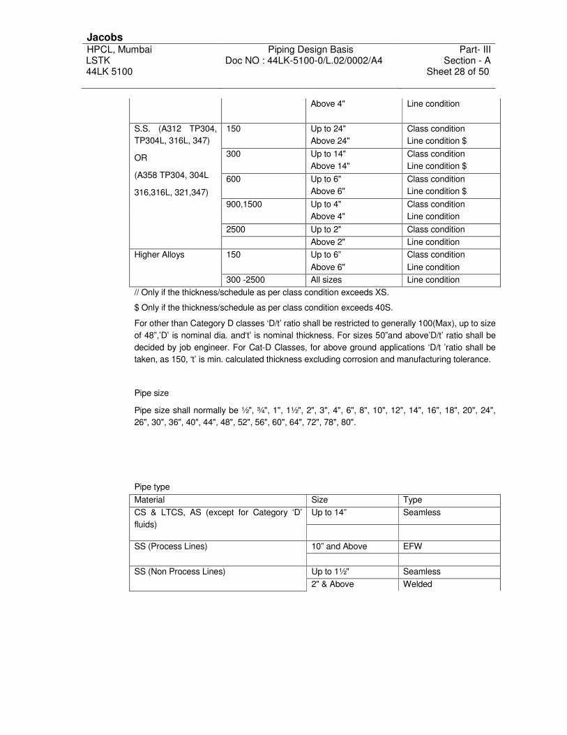
Jacobs HPCL, Mumbai Piping Design Basis Part- III LSTK Doc NO : 44LK-5100-0/L.02/0002/A4 Section - A 44LK 5100
Sheet 28 of 50
Above 4" Line condition
150 Up to 24" Class condition
Above 24" Line condition $
300 Up to 14" Class condition
Above 14" Line condition $
600 Up to 6" Class condition
Above 6" Line condition $
900,1500 Up to 4" Class condition
Above 4" Line condition
2500 Up to 2" Class condition
S.S. (A312 TP304,
TP304L, 316L, 347)
OR
(A358 TP304, 304L
316,316L, 321,347)
Above 2" Line condition
150 Up to 6” Class condition
Above 6" Line condition
Higher Alloys
300 -2500 All sizes Line condition
// Only if the thickness/schedule as per class condition exceeds XS.
$ Only if the thickness/schedule as per class condition exceeds 40S.
For other than Category D classes ‘D/t’ ratio shall be restricted to generally 100(Max), up to size
of 48”,’D’ is nominal dia. and‘t’ is nominal thickness. For sizes 50”and above’D/t’ ratio shall be
decided by job engineer. For Cat-D Classes, for above ground applications ‘D/t ’ratio shall be
taken, as 150, ‘t’ is min. calculated thickness excluding corrosion and manufacturing tolerance.
Pipe size
Pipe size shall normally be ½", ¾", 1", 1½", 2", 3", 4", 6", 8", 10", 12", 14", 16", 18", 20", 24",
26", 30", 36", 40", 44", 48", 52", 56", 60", 64", 72", 78", 80".
Pipe type
Material Size Type
Up to 14” Seamless
CS & LTCS, AS (except for Category ‘D’
fluids)
10” and Above EFW
SS (Process Lines)
Up to 1½" Seamless
SS (Non Process Lines)
2" & Above Welded

Jacobs HPCL, Mumbai Piping Design Basis Part- III LSTK Doc NO : 44LK-5100-0/L.02/0002/A4 Section - A 44LK 5100
Sheet 29 of 50
CS (Category ‘D’ fluids)
* Except for fire water and cooling water
services, for which following shall apply:-
1. Up to 6” NB - Seamless
2. 8” NB and above - Welded
3. Less than 3” NB - Carbon steel
( Higher schedule )
4. 3 inch NB and above - Carbon Steel
(Cement Lined)
ALL
Welded *
3.9.2 Fittings
Type of fittings shall be equivalent to pipe type.
Thickness of fittings at ends to match pipe thickness for BW fittings
SW fittings shall be 3000#, 6000#, and 9000# depending on the pipe thickness S80, S160 and
above S160 respectively.
Up to 600# all branch connections shall be as follows, unless specifically mentioned otherwise
in PMS.
Up to 1½" NB Half Coupling / Tee
2" and above Tee/ Pipe to pipe with / without
reinforcement pad
For branch connection above 600# rating equal tee/unequal tee shall be used for all sizes.
Unequal tee may be replaced by weld-o-let up to branch size of 8".
Miters shall be used in Category ‘D’ service above 6"NB. For other than category ‘D’ fluids in
150#, 300# classes’ miters may be able to be permitted for sizes above 48" only. Miters to be
designed as per ASME B 31.3.However use of miters shall be minimum.

Jacobs HPCL, Mumbai Piping Design Basis Part- III LSTK Doc NO : 44LK-5100-0/L.02/0002/A4 Section - A 44LK 5100
Sheet 30 of 50
3.9.3 Flanges:
Flanges:
Flanges shall be as follows:
Class Size Type Remarks
Up to 1½" SW RF If non-metallic gasket used.
Up to 1½" WN RF If metallic gasket used.
2" & above WN RF/LJ FF For SS LJ FF + Stub ends
150#
2" & above SO RF If used in Category ‘D’ service
300#, 600# Up to 1½" SW RF
2" & above WN RF
900#, 1500#, 2500# All WN RTJ
All flange joints on piping system including flanges on equipment, manhole, etc shall be tightened using torque wrench/ hydraulic bolt tensioner depending upon service criticality.
3.9.4 Gaskets.
Gaskets to be provided as per service condition as mentioned in PMS.
3.9.5 Valves
SW valves up to 1½ inch – up to 600# ANSI Class except ball and plug valves which shall be flanged for all sizes.
Flanged cast valve above 1½" – 150#, 300#, 600# ANSI Class
BW valves all sizes-900# ANSI Class & above No CI valves to be used.
Over and above requirements, other technical requirement prescribed in Annexure E shall also be adhered to.
3.10 NON DESTRUCTIVE TESTING REQUIREMENTS
Depending on the severity of application, extent of NDT shall be decided. As a rule, all
hydrogen, oxygen, NACE and any other lethal service shall have 100% radiography on weld
joints. Castings used in these services shall have 100% radiography. For high-pressure
applications i.e. 600# upward 100% radiography on weld joints shall be employed. In 100%
radiography classes any fillet welds employed shall have 100% MP in CS/AS classes and
100% DP in SS classes. Category ‘D’ service shall have 2% radiography. Classes in 150#
for normal hydrocarbon service shall be subjected to 10% radiography and SW/Fillet
weld/attachment weld where radiography is not possible shall be 10% DP/MP tested.
Classes in 300# for normal hydrocarbon service shall be subjected to 20% radiography and
SW/ Fillet weld/attachment weld where radiography is not possible shall be 20% DP/MP
tested.

Jacobs HPCL, Mumbai Piping Design Basis Part- III LSTK Doc NO : 44LK-5100-0/L.02/0002/A4 Section - A 44LK 5100
Sheet 31 of 50
All AS pipes, fittings, flanges, valves & bolts shall undergo Positive Material Identification
(100%) at site. All the PMI test at construction site shall be done as per standard.
3.11 STRAINERS
3.11.1 Temporary Strainers:
1½" & below for all services shall by Y-type
2" & above for steam service shall by Y-type
2" & above for other than steam services shall by T-type
3.11.2 Permanent strainers
Compressor suction, cold box inlet strainers shall be cone type with reinforced perforated
sheet cage design
1" & above permanent strainer shall be as per process data sheet
3.12 WELDING
3.12.1 Applicable codes and standards
All welding work, equipment for welding, heat treatment, other auxiliary functions and the
welding personnel shall meet the following requirements of the latest edition of following
accepted standards and procedures.
Process piping – ASME B 31.3
In addition, the following codes and specification referred in the code of fabrication shall be
followed for the welding specifications, consumables, qualifications and non-destructive test
procedures.
Welding and Brazing qualifications – ASME BPV Sec IX
Non Destructive Test - ASME BPV Sec V
Material specification: welding rods, electrodes, and filler metals – ASME BPV Sec II part
C The additional requirements mentioned in this specification, over and above those obligatory
as per codes, shall be followed wherever specified.
3.12.2 Welding processes
3.12.2.1 Welding of various materials shall be carried out using one or more of the following
Shielded Metal Arc Welding process (SMAW)
Gas Tungsten Arc Welding (GTAW)
3.12.2.2 Automatic and semi-automatic welding shall be employed only with the approval of the
Owner. The welding procedure adopted and consumables used shall be specifically
approved.
3.12.2.3 All steam tracing line to be welded with TIG welding process and subjected to hydro test
prior to commissioning.

Jacobs HPCL, Mumbai Piping Design Basis Part- III LSTK Doc NO : 44LK-5100-0/L.02/0002/A4 Section - A 44LK 5100
Sheet 32 of 50
3.12.2.4 A combination of different welding processes could be employed for a particular joint only
after duly qualifying the welding procedure to be adopted and obtaining the approval of
Owner.
3.12.2.5 For additional details "welding specification for fabrication of piping” / welding charts shall be
referred.
4.0 REFERENCED PUBLICATIONS
The following latest codes and standards shall be followed unless otherwise specified.
ASME SEC. I - Rules for Construction of Power Boilers.
ASME SEC. VIII
- Rules for Construction of Pressure Vessels.
ASME B31.1 - Power piping.
ASME B31.3 - Process piping.
ASME B 31.8 - Guide for Gas Transmission and Piping distribution system
ANSI/NEMA
SM 23
- Steam turbines for mechanical drive service.
API RP 520 - Sizing, selection and installation of Pressure relieving devices in
Refineries.
API Std. 560 - Fired heaters.
API Std. 610 - Centrifugal pumps for Petroleum, Heavy-duty chemical and gas
industry service.
API Std. 617 - Centrifugal compressors for petroleum, chemical and gas industry
service.
API Std. 618 - Reciprocating Compressors
API Std. 661 - Air cooled heat exchangers
EJMA - Expansion joints Manufacturers’ Association.
NACE
MR-0175
- Sulphide Stress cracking resistant metallic materials for oilfield
equipment.
NACE
TM-
0177
- Laboratory testing of metals for resistance to Sulphide Stress
cracking in H2S Environments.
NACE
MR-
0284
- Evaluation of pipeline and pressure vessel steel for resistance to
Hydrogen Induced Cracking.
IBR - Indian Boiler Regulations
TAC - Tariff Advisory Committee.
OISD - Oil Industry Safety Directorate.
OISD 118 - Layouts for oil and gas installation.

Jacobs HPCL, Mumbai Piping Design Basis Part- III LSTK Doc NO : 44LK-5100-0/L.02/0002/A4 Section - A 44LK 5100
Sheet 33 of 50
OISD 116 - Fire protection facilities for petroleum refineries and oil/gas
processing plants.
OISD 113 - Classification of area for electrical installation at hydrocarbon and
handling facilities.
OISD 164 - Fire proofing in Oil & Gas industry
IS 5572 - Classification of Hazardous area (other than mines) for electrical
installation.
ANNEXURE A
Accessibility for valves and instruments
Valves, instrument, equipment to
be operated
Centerline of item to be operated,
located less than 3.6 m above
grade, 2.75m above floor or
platform or 1.8m above wing
platform.
Centerline of item to be
operated, located more than
3.6 m above grade, 2.75m
above floor or platform or
1.8m above wing platform.
Exchanger heads Nil Platform
Oper. Valves 2" & smaller Fixed ladder Fixed ladder
Oper. Valves 3" above Platform Platform
Motor operated valves Platform Platform
Control valves Platform Platform

Jacobs HPCL, Mumbai Piping Design Basis Part- III LSTK Doc NO : 44LK-5100-0/L.02/0002/A4 Section - A 44LK 5100
Sheet 34 of 50
Relief valves 2" & smaller Fixed ladder Fixed ladder
Relief valves 3" & above Platform Platform
Block valves 2" & smaller Portable ladder Platform
Block valves 3" & above Platform note – 1 Platform
Battery limit valves Platform Platform
Pressure instrument Fixed ladder if above 2.2 m Fixed ladder
Temperature instrument Fixed ladder if above 2.2 m Fixed ladder
Sample points Platform Platform
Gauge glasses Fixed ladder Platform
Level controllers Platform Platform
Process blinds and spades 2" &
above
Portable ladder/platform Platform
Process blinds and spades 3" &
above
Platform Platform
Man ways / manholes Platform Platform
Manholes / inspection holes Platform Platform
Nozzles Access required Platform
Vessel vents Portable ladder Fixed ladder
Line drains & vents Portable ladder Portable ladder
Orifice flanges Portable ladder Portable ladder
Note: - 1. Centerline or block valves located above 2.0 meter from the operating floor, which are
required for normal operation, shall be provided with portable platform or chain for operation of valves.
ANNEXURE B
CLEARANCES
Equipment, Structure, Platforms, Piping & its supports shall be arranged so as to provide the following
clearances.
A OVERHEAD CLERANCES
1. Over rail roads, top of rail to bottom of any obstruction. 9 m
2. Over plant roads for major mobile equipment 9 m
3. Over grade & bottom of pipe (inside battery limit) 4.5 m
4. Over walk-ways, pass-ways & platforms to nearest
obstruction and inside building
2.2m
5. Over Exchangers at Grade, shell cover channel end. 1.5 m

Jacobs HPCL, Mumbai Piping Design Basis Part- III LSTK Doc NO : 44LK-5100-0/L.02/0002/A4 Section - A 44LK 5100
Sheet 35 of 50
B. HORIZONTAL CLEARANCES
1. Between Exchangers (Aisles between Piping). 0.9 m or 2m centre to centre
whichever is higher
2. Around Pumps (Aisles between piping) 0.9 m
3. Fired heaters to pumps handling flammable stock 15 m
4. Fired heaters to other flammable containing equipment and
closely associated with heaters.
15 m
5. At driver end of pumps where truck/fork lifter access is
required.
4 m
6. At driver end of pumps where truck access is not required. 1.8 m
7 At shell cover end of exchangers at grade, for access way 1.3 m
8 Between shells of adjacent horizontal vessels 2.0 m or 0.9m clear aisle
whichever is higher
C EQUIPMENT SPACING
1. Small size pumps
(13.7 KW & Less)
Mount on common
foundations suitable centre to
centre distance.
2. Middle size pumps
(22.5 KW & Less)
0.9m clears Aisle between
associated piping.
3. Large size pumps
(Above 22.5 KW)
0.9m clears Aisle between
associated piping.
4. Exchangers and other equipment on structures 0.9m clears Aisle between
associated piping.
D PLATFORMS
1. TOWERS, VERTICAL & HORIZONTAL VESSELS
i. Distance of platform below centerline of
manhole flange-side platform.
0.9-1.05 m
ii. Width of manhole platform from manhole
cover to outside edge of platform
1.0 m
Iii Platform extension beyond centre line of
manhole – side platform.
1.0 m
iv. Distance of platform below under side of
flange – Head platform
1.75 m

Jacobs HPCL, Mumbai Piping Design Basis Part- III LSTK Doc NO : 44LK-5100-0/L.02/0002/A4 Section - A 44LK 5100
Sheet 36 of 50
v. Width of Platform from three sides of
manhole – Head platform
0.75 m
2. HORIZONTAL EXCHANGER
i. Clearance in front channel or Bonnet
flange.
1.3 m
Ii Heat exchanger tube bundle removal
space.
Bundle length + 1.5 m
Iii Min. clearance from edge of flanges. 0.1 m
3. VERTICAL EXCHANGER
i. Distance of platform below top flange of
channel on bonnet.
1.5 m
4. FURNACES
i. Width of the platform at side of horizontal
and vertical tube furnace.
2.0 m Min.
Ii Width of the platform at ends of horizontal
tube furnace.
2.0 m Min.

Jacobs HPCL, Mumbai Piping Design Basis Part- III LSTK Doc NO : 44LK-5100-0/L.02/0002/A4 Section - A 44LK 5100
Sheet 37 of 50
ANNEXURE C
Vertical and Horizontal Guide Spacing
Pipe Size (Inch) Guide Spacing in meters
Vertical Horizontal
1 6 6
1½ 6 6
2 6 6
3 8 12
4 8 12
6 8 12
8 8 12
10 12 18
12 12 18
14 12 18
16,18 12 18
20 16 18
24 16 18
26 and above 16 18
Notes:
These spacing may be varied to suit column spacing of rack. The above spacing is for straight runs of
pipe and does not include guides, which are used for control of thermal movements, as decided by
stress group.
The guide spacing given in the above table is indicative only.
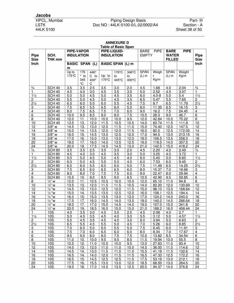
Jacobs HPCL, Mumbai Piping Design Basis Part- III LSTK Doc NO : 44LK-5100-0/L.02/0002/A4 Section - A 44LK 5100
Sheet 38 of 50
ANNEXURE D Table of Basic Span
PIPE-VAPOR INSULATION
PIPE-LIQUID-INSULATION
BARE PIPE EMPTY
BARE PIPE WATER FILLED
BASIC SPAN (L) m
BASIC SPAN (L) m
Pipe Size Inch
SCH. THK mm
Up to 175°C
176
° to 345
°C
446°
C to
400°
C
Up to
175°C
176°C to
445°C
346°C to
400°C
SPAN (L) m
Weight Kg/m
SPAN (L) m
Weight Kg/m
Pipe Size Inch
¾ SCH 40 3.5 3.5 2.5 3.5 3.0 2.0 4.5 1.68 4.0 2.04 ¾ 1 SCH 40 4.5 4.0 3.0 4.5 3.5 3.0 5.0 2.52 4.5 3.07 1 1½ SCH 40 5.0 5.0 4.5 5.0 4.5 3.5 6.0 4.0-8 5.0 5.4 1½ 2 SCH 40 5.5 5.0 4.5 5.0 4.5 3.5 6.5 5.47 5.5 7.65 2 2½ SCH 40 6.5 6.0 5.0 6.0 5.5 4.5 7.5 8.7 6.5 11.79 2½ 3 SCH 40 7.5 6.5 5.5 6.5 6.0 5.0 8.0 11.35 6.5 16.15 3 4 SCH 40 8.0 7.5 6.5 7.5 7.0 6.0 9.0 16.2 7.5 24.45 4 6 SCH 40 10.0 9.5 8.5 9.0 8.0 7.5 10.5 28.3 9.0 46.7 6 8 SCH 40 12.0 11. 10.0 10.0 10.0 9.0 12.0 42.84 10.0 75.22 8 10 SCH 40 13.5 13. 12.0 11.5 10.5 10.5 14.0 60.74 11.5 111.9 10 12 3/8" w 14.5 13. 13.0 12.0 11.5 11.0 15.0 74.40 12.0 147.5 12 14 3/8" w 15.0 14. 13.5 12.0 12.0 11.5 16.0 82.5 12.5 172.05 14 16 3/8" w 16.0 15. 14.5 13.0 12.5 12.0 17.0 94.5 13.0 213.15 16 18 3/8" w 17.0 16. 15.0 13.5 13.0 12.0 18.0 106.5 13.5 258.3 18 20 3/8" w 18.0 17. 16.0 14.0 13.5 12.5 19.0 118.5 14.0 307.5 20 24 3/8" w 20.0 19. 17.5 14.5 14.5 13.0 21.0 142.5 15.0 418.2 24 ¾ SCH 80 3.5 3.5 2.5 3.5 3.0 2.0 4.5 2.20 4.0 2.49 ¾ 1 SCH 80 4.5 4.0 3.0 4.5 3.5 3.0 5.0 3.25 4.5 3.72 1 1½ SCH 80 5.0 5.0 4.5 5.0 4.5 4.0 6.0 5.45 5.0 6.60 1½ 2 SCH 80 6.0 5.0 4.5 5.5 5.0 4.0 6.0 7.53 6.0 9.45 2 2½ SCH 80 6.5 6.0 5.5 6.0 6.0 5.0 7.5 11.49 6.5 14.25 2½ 3 SCH 80 7.5 6.5 6.0 6.5 6.5 6.0 8.0 15.37 7.0 19.66 3 4 SCH 80 8.0 8.0 7.0 7.5 7.5 6.5 9.0 22.47 8.0 29.94 4 6 SCH 80 10.5 10. 9.0 9.5 9.0 8.5 10.5 42.90 9.5 59.85 6 8 ½" w 12.0 11. 10.5 10.5 10.0 10.0 12.0 65.10 11.0 94.8 8 10 ½" w 13.5 13. 12.0 11.5 11.5 10.5 14.0 82.20 12.0 130.69 10 12 ½ "w 14.5 13. 13.0 12.5 12.0 11.5 15.0 98.13 13.0 168.64 12 14 ½ "w 15.0 14. 13.5 13.0 12.5 12.0 16.0 108.1 13.5 194.4 14 16 ½ "w 16.0 15. 15.0 13.5 13.0 13.0 17.0 124.2 14.0 240.0 16 18 ½ "w 17.5 17. 16.0 14.5 14.0 13.5 18.0 140.2 14.5 286.64 18 20 ½" w 18.0 17. 17.0 15.0 14.5 14.0 19.0 157.0 15.0 341.8 20 24 ½" w 20.0 19. 18.5 16.0 15.0 15.0 21.0 188.2 16.0 458.44 24 1 10S 4.0 3.5 3.0 4.0 3.0 2.5 4.5 2.08 4.0 2.7 1 1½ 10S 5.0 4.5 3.5 4.5 4.0 3.0 5.5 3.12 5.0 4.57 1½ 2 10S 5.0 4.5 3.5 4.5 4.0 3.0 6.0 3.94 5.5 6.63 2 2½ 10S 6.5 5.5 4.5 5.5 5.0 4.5 7.0 5.26 6.0 8.85 2½ 3 10S 7.0 6.0 5.0 6.0 5.5 5.0 7.5 6.45 6.0 11.91 3 4 10S 7.5 7.0 6.0 6.5 6.0 6.0 8.0 8.34 7.0 17.67 4 6 10S 9.5 9.0 8.0 8.0 7.5 7.5 10.0 13.82 8.5 34.54 6 8 10S 11.0 10. 10.0 9.5 9.5 8.5 11.5 19.94 10.0 55.5 8 10 10S 12.5 12. 11.0 10.5 10.0 9.5 13.0 27.83 11.0 83.4 10 12 10S 14.0 13. 12.0 11.0 11.0 10.0 14.5 36.00 11.5 114.6 12 14 10S 14.5 14. 13.0 11.5 11.0 11.0 15.5 41.18 11.5 132.6 14 16 10S 16.5 14. 14.0 12.0 11.5 11.5 16.5 47.33 12.5 172.2 16 18 10S 16.5 15. 14.5 12.5 12.5 11.5 17.5 53.18 13.0 212.1 18 20 10S 17.5 16. 15.5 13.0 13.0 12.0 18.5 68.50 13.0 264.5 20 24 10S 19.0 18. 17.0 14.0 13.5 12.5 20.5 94.37 14.0 376.8 24

Jacobs HPCL, Mumbai Piping Design Basis Part- III LSTK Doc NO : 44LK-5100-0/L.02/0002/A4 Section - A 44LK 5100
Sheet 39 of 50
ANNEXURE E
TECHNICAL REQUIREMENTS OF PIPING MATERIAL
1.0 Ends
Unless otherwise specified the ends shall be to the following standard:
SW/SCRD ASME B16.11
BW ASME B16.25 / B16.9
FLANGED ASME B16.5 and ASME B16.47 SERIES ‘B’/API-605
THREADING ASME/ANSI B1.20.1 (NPT, Taper threads)
2.0 Face Finish
This shall be to MSS-SP-6/ASME B46.1/ ASME B16.5. The interpretation shall be :
Stock Finish 250-1000 µ in AARH
Serrated Finish 250-500 µ in AARH
Smooth Finish/125 AARH 125-250 µ in AARH
Extra Smooth Finish /63 AARH 32-63 µ in AARH
3.0 Austenitic Stainless Steel
All items/ parts shall be supplied in solution-annealed condition.
Intergranular Corrosion (IGC) Test shall be conducted as per following:
ASTM A262 Practice ‘B’ with acceptance criteria of 60-mils/ year (max.) for casting.
ASTM A262 Practice ‘E’ with acceptance criteria of ‘No cracks as observed from 20X
magnification & microscopic structure to be observed from 250X magnification" for other
than casting.
For IGC test, two sets shall be drawn from each solution annealing lot: one set
corresponding to highest carbon content and other set corresponding to the highest
rating/ thickness.
IGC test is a must for all stainless steel classes.
For all items of stabilized SS grades, stabilizing heat treatment shall also be done. It shall
be carried out subsequent to normal solution annealing. Soaking temperature and holding
time shall be 900 Deg. C and 4 hours respectively.
4.0 Item specific notes:
4.1 Pipes
Double seam is allowed for sizes 36" and larger.

Jacobs HPCL, Mumbai Piping Design Basis Part- III LSTK Doc NO : 44LK-5100-0/L.02/0002/A4 Section - A 44LK 5100
Sheet 40 of 50
Galvanized pipes shall be only Hot Dip galvanized To ASTM A53.
Pipes greater than 10" spiral welded/ pipe shall be used weld seams to be kept in upper
quadrant only.
4.2 Fittings
All fittings shall be seamless in construction unless otherwise specified.
For reducing BW fittings having different wall thickness at each end, the greater one shall
be employed and the ends shall be matched to suit respective thickness.
All welded fittings shall be double welded. Inside weld projection shall not exceed 1.6
mm, and the welds shall be ground smooth at least 25mm from the ends.
For fittings made out of welded pipe, the pipe itself shall be of double welded type,
manufactured with the addition or filler material and made employing automatic welding
only.
All welded fittings shall be normalized for CS, normalized & tempered for AS: and 100 %
radiographed by X-ray for all welds made by fitting manufacturer as well as for welds on
the parent material.
Bevel ends of all BW fittings shall undergo 100 % MP/DP test. Those used in fire fighting
facility should be marked
Tell-tale hole to be tapped in all reinforcement pads.
4.3 Flanges
For Ring Joint Flanges, Blinds and Spacers, the hardness shall be as follow:
Flange Material Min. hardness of Groove
(BHN)
Carbon Steel 120
1 % Cr. To 5% Cr. ½ Mo 150
Type 304,316, 347, 321 180
Type 304 L, 316 L 140
For RTJ flanges, blinds & spacers, the hardness of the groove shall be specified on the
test report.
Bore of weld neck flange shall correspond to the inside diameter of pipe for specified
schedule/ thickness. Ends shall be beveled to suit the specified schedule/ thickness.
All flange joints to be tightened with proper gaskets, bolts & nuts with skilled technician
and box-up of flange joints to be documented.

Jacobs HPCL, Mumbai Piping Design Basis Part- III LSTK Doc NO : 44LK-5100-0/L.02/0002/A4 Section - A 44LK 5100
Sheet 41 of 50
4.4 Valves
Valves of Class 900# & above shall be pressure-seal type. Threaded and seal welded or
welded bonnet may be employed up to sizes 1-1/2".
All flanged valves (except forged) shall have flanges integral with the valve body.
Yoke material shall be at least equal to body material.
Forgings are acceptable in place of Castings but not vice-versa.
No cast iron valves to be used in fire fighting or any other service except in drinking water
service
Valve castings/ forgings purchased from India or Indian Vendors shall be from Owner
approved foundries/ forging shop.
4.5 Dimensions
Face-to-Face/End-to-End dimension shall be as per ANSI B16.10. In case the same is
not covered under B16.10, the dimension shall be as per BS 2080/Manufacturer’s Std.
Valve under cryogenic service (temp.below-45°C) shall be as per BS-6364 and shall be
procured from pre-qualified vendor.
4.6 Operation
Generally the valves are hand wheel or lever operated. However, suitable gear operator
in enclosed gear box shall be provided for valves as follows;
TYPE OF VALVE ANSI CLASS SIZES
Gate 150 300 600 900
1500 2500
14" and larger 12" and larger 8" and larger 6" and larger 4" and larger 2" and larger
Ball 150 and 300 600 and over
6" and larger Manufacturer's Std.
Plug 150 300
8" and larger 6" and larger
Butterfly all 8" and larger
Globe 150 and 300 600 900
1500 and 2500
8" and larger 6" and larger 4" and larger 3" and larger
Hand wheel diameter shall not exceed 750 mm and lever length shall not exceed 500 mm
on each side. Effort to operate shall not exceed 35 kgf at hand wheel periphery.
However, failing to meet the above requirement, vendor shall offer gear operation.
Quarter-turn valves shall have "open" position indicators with limit stops.

Jacobs HPCL, Mumbai Piping Design Basis Part- III LSTK Doc NO : 44LK-5100-0/L.02/0002/A4 Section - A 44LK 5100
Sheet 42 of 50
4.7 By pass
A globe type valve (size as per ASME/ANSI B16.34) shall be provided as bypass for the
following sizes of gate valves:
Class For sizes
150 # 26" and above
300 # 16" and above
600 # 6" and above
900 # 4" and above
1500 # 4" and above
2500 # 3" and above
By-pass piping, fitting and valves shall be compatible material and design. Complete fillet
welds for by-pass installation shall be DP/MP tested. NDT of by-pass valve shall be inline
with main valve.
4.8 Radiography of cast valves
Unless specified otherwise, the following valve castings shall undergo radiographic
examination (for all materials):
Class Size Qty.
150 # 26" & above 100 % (Except for Cat. ‘D’
service)
300 # 18" & above 100 %
600 # & ABOVE All 100 %
For Hydrogen, Oxygen, NACE, Stress relieved, Caustic service, additional radiography
requirements shall be as follows (Over & above the requirements covered under Para.
above):
150 # Up to 24" 50 %
300 # Up to 16" 50 %
For CRYO/Low temperature classes, additional radiography requirements shall be as follows
(Over & above the requirements covered under Para. ‘A’ above):
150 # Up to 24" 20%
300 # Up to 16" 20%
For alloy steel, Stainless steel castings (not covered in Para B&C above) shall be additionally
radiographed as follows:
150 # Up to 24" 10%

Jacobs HPCL, Mumbai Piping Design Basis Part- III LSTK Doc NO : 44LK-5100-0/L.02/0002/A4 Section - A 44LK 5100
Sheet 43 of 50
300 # Up to 16" 10%
Radiography procedure, areas of casting to be radiographed, and the acceptance criteria
shall be as per ASME/ANSI B16.34.
All casting in class 300 # & above shall be radiographic quality casting. This requirement to
be ensured by sample radiography before proceeding with the actual production
4.9 Ball/plug/butterfly valves
Each valve shall be supplied with a lever/wrench except for gear operated/ motor operated
valves.
Soft-seated Ball, Plug & Butterfly valves shall be supplied and antistatic devices.
All Ball; Plug & Butterfly valves shall be fire safe to atmosphere.
The ball of Ball Valves shall not protrude outside the end flanges.
Ball valves shall be floating ball type/ trunion mounted type as per following:
Plug valves, if used shall be of pressure balanced type
Class Floating Ball Trunion Mounted
150 # 8" & below 10" & above
300 # 4" & below 6" & above
600 # & above 1 ½ & below 2" & above
Use of soft-seated ball/plug/butterfly valves shall be suitably selected based on temperatures
handled. Butterfly valve shall be suited for throttling application.
4.10 Strainer
Allowable pressure drop shall be certified by vendor along with the offer. If asked
specifically, vendor shall furnish pressure drop calculations.
All 2" & higher sized Y type strainer shall be provided with ¾" threaded tap and solid
threaded plug as drain connection. For less than 2", this shall be ½" size.
Bottom flange of Y-type strainer shall not have tapped holes. Full length standard size studs
shall be used for joining blind flanges
For fabricated strainers, all BW joints shall be fully radiographed and fillet welds shall be 100
% DP/MP checked.
All the strainers shall be hydrostatically tested at twice the design pressure.
4.11 Traps
Jacobs HPCL, Mumbai Piping Design Basis Part- III LSTK Doc NO : 44LK-5100-0/L.02/0002/A4 Section - A 44LK 5100
Sheet 44 of 50
Vendor shall also furnish the performance curve indicating the capacity in mass/hour at
various differential pressures across the trap.
Parts subject to wear and tear shall be suitably hardened.
Traps shall function in horizontal as well as in vertical installation.
Traps shall have integral strainers.
All traps shall be hydrostatically tested to twice the design pressure
4.12 Hoses
Manufacturer shall guarantee suitability of hoses for the service and working conditions
specified in the requisition, if the material is not specified in the Material Requisition for
any particular service.
All hoses shall be marked with service and working pressure at minimum two ends
clearly.
Hoses shall be resistant to ageing, abrasion and suitable for outdoor installations.
Complete Hose assembly shall be tested at two times the design pressure.
Flexible hose of hydrogen reformer should be of SS316 or equivalent to resist chloride
corrosion.
Steam hoses shall be subject to steam resistant test.
4.13 Expansion Joints
The applicable codes are ASME B 31.3 and EJMA (Expansion Joint Manufacturer’s
Association).
Bellows shall be formed from solution annealed sheet conforming to the latest ASTM
Spec. Any longitudinal weld shall be 100 % radiographed. The finished longitudinal
weld must be of the same thickness and same surface finish as the parent material.
Circumferential welds are not permitted. Bellows are to be hydraulically or expansion
(punched) formed. Rolled formed bellows are not acceptable. Noticeable punch or die
marks resulting from expansion operation are not acceptable.
No repairs of any kind are allowed on the bellows after forming. Deep scratches and
dents are not acceptable.
The out of roundness shall be limited to ± 3mm. This is the max. Deviation between the
max. & min. diameter.
The actual circumference of the welding end shall be maintained to ± 3 mm of the
theoretical circumference.
Apart from the usual requirements, the vendor shall also furnish:
Design calculations to justify stiffness and fatigue life.
Axial, lateral stiffness, angular stiffness, effective pressure thrust area.
Installation maintenance manual

Jacobs HPCL, Mumbai Piping Design Basis Part- III LSTK Doc NO : 44LK-5100-0/L.02/0002/A4 Section - A 44LK 5100
Sheet 45 of 50
Bellows should be designed for 10,000 cycles (ANSI B31.3) minimum
4.14 Supporting & Spring Assemblies
The material Design, Manufacture and Fabrication shall be generally as per MSS-SP-
58/MSS-SP-89 and/or BS 3974.
Testing of springs shall be as per BS1726
4.15 Gaskets
Filler for spiral wound gasket shall not have any color or dye.
Full-face gaskets shall have boltholes punched out.
Non-metallic ring gaskets as per ASME/ ANSI B 16.21 shall match flanges to ASME/
ANSI B16.5 up to 24" and ASME/ANSI B16.47 OR AWWA for sizes > 24" unless
otherwise specified.
Spiral wound gaskets as per ASME B16.20 shall match flanges to ASME/ANSI B16.5
up to 24" and ASME B16.47 series B’ for sizes > 24", unless otherwise specified.
Inner and outer rings shall be considered for spiral wound gaskets based on under
mention philosophy.
CAF Gaskets shall not be used.
4.16 Outer Ring
C.S. outer ring irrespective of temperature-spiral strip material (except subzero
temperatures).
4.17 Inner Ring:
Material of inner ring to be C.S. for C.S. classes & same as that of spiral strip material
for other than C.S. classes.
As per code ANSI B 16.20
26" & above for all classes.
All sizes for vacuum classes, Cryo services and Hydrogen services.
2" & above for Hydrogen classes
All sizes in ‘H’ grades of S.S. SS347, SS321 classes.
For all sizes for classes with temperature beyond 427 ° C.
For piping class 900# and above
4.18 SPECIAL SERVICE REQUIREMENTS

Jacobs HPCL, Mumbai Piping Design Basis Part- III LSTK Doc NO : 44LK-5100-0/L.02/0002/A4 Section - A 44LK 5100
Sheet 46 of 50
Requirements given below shall be supplemented with detailed requirements included
in the PIPING MATERIAL SPECIFICATION.
4.18.1 IBR
IBR stands for Indian Boiler Regulation. For steam services, it is statutory obligation to
meet IBR requirements.
For items under IBR, composition restrictions, test reports, painting, etc. shall be as per
IBR’s stipulations.
4.18.2 NACE & Sour Service
For items under this category, NACE MR01-75 shall be followed. Hardness shall be
below BH No.200 for CS material. Carbon equivalent (CE) shall be limited to 0.43.
4.18.3 Impact tests
Welded pipes and fittings used below ASME temp. – 29°C shall be impact tested as
per requirement of ASME B31.3. Impact test shall also be carried out as per process
Licensor’s requirement in addition to ASME B31.3
4.19.0 SPECIAL REQUIREMENTS FOR HYDROGEN SERVICE
4.19.1 GENERAL
Vendor quality plan shall include the special quality checks and inspection
requirements for these services.
For operating temperatures below 230°C, materials shall be of carbon steel to the
appropriate specifications
For operating temperatures of 230°C and above, materials shall be selected on the
basis of Nelson Curves of API Publication No. 941 (Steels for hydrogen service at
elevated temperatures and pressures in petroleum refineries and petrochemical
plants).
Impact test &normalizing of CS/AS materials shall be as mentioned in the code.
4.19.2 PIPE, FLANGES AND FITTINGS
4.19.2.1 Method of manufacture
All CS pipes, fittings and flanges having wall thickness 9.53mm and above, shall be
normalized. Cold drawn pipes and fittings shall be normalized after the final cold draw
pass for all thickness. In addition, fittings made from forgings shall have Carbon –
0.35% max. And Silicon - 0.35% max. The normalizing heat treatment shall be a
separate heating operation and not a part of hot forming operation.
All Alloy Steel (Cr.-Mo) pipes, forgings and fittings shall be normalized and tempered.
The normalizing and tempering shall be a separate heating operation and not a part of
hot forming operation. The maximum room temperature tensile strength shall be
100,000 psi.
In addition, details given by process licensor’s requirements shall be met.
Jacobs HPCL, Mumbai Piping Design Basis Part- III LSTK Doc NO : 44LK-5100-0/L.02/0002/A4 Section - A 44LK 5100
Sheet 47 of 50
4.19.2.2 Post Weld Heat Treatment
All carbon steel pipes and fittings having wall thickness 19 mm and above shall be post
weld heat-treated.
All alloy steel (cr-mo) pipes and fittings shall be post weld heat treated irrespective of
type or thickness of weld.
All austenitic stainless steel grades shall be solution annealed after welding.
4.19.2.3 Ferrite No. Test
For all austenitic stainless steel, the weld deposit shall be checked for ferrite content. A
ferrite No. (FN) not less than 3% and not more than 10% is required to avoid sigma
phase embrittlement during heat treatment. FN shall be determined by Ferrite scope
prior to post-to-post weld heat treatment.
4.19.2.4 Impact Test
For all carbon steel and alloy steel pipes, flanges and fittings with the wall thickness
over 19 mm, Carpy-V Notch impact testing shall be carried out in accordance with
paragraph UG-84 of ASME Section VIII, Div-1 for weld metal and base metal from the
thickest item per heat of material and per heat treating batch. Impact test specimen
shall be in complete heat-treated condition and in accordance with ASTM A370.impact
energies at 0°c shall be average greater than 27 J (20 ft-lb) per set of 3 specimens,
with a minimum of 19J (15 ft-lb).
If welding is used in manufacture, impact test of Heat Affected Zone (HAZ) and welds
metal shall also be carried out.
In addition top the details given process licensor’s shall be met.
4.19.2.5 Hardness
For carbon steel pipes and fittings, hardness of weld and HAZ shall be limited to
200BHN(Max)
For alloy pipes and fittings, hardness of weld and HAZ shall be limited to 225BHN(Max)
4.19.2.6 Radiography
All girth welded joints (longitudinal and circumferential) shall be 100% radiographed in
accordance with UW-51 of ASME section VIII Div-1 and ASME Section V
4.19.2.7 Valves
All valves castings shall be radiographic quality.
Jacobs HPCL, Mumbai Piping Design Basis Part- III LSTK Doc NO : 44LK-5100-0/L.02/0002/A4 Section - A 44LK 5100
Sheet 48 of 50
All cast valves flanges & bodies with flange rating of class 900 pr greater shall be
examined in accordance with paragraphs 7.2 through 7.5of Appnedix-7 of ASME SEC-
VIII DIV-1, regardless of casting quality factor.
4.20 INSPECTION & TESTING
All items and their parts shall be subjected to all mandatory as well as supplementary
(wherever specified) tests and checks called for in the respective codes/standards/data
sheets).
All critical service valves shall be hydro tested at site for leak test before installation. All
facility for testing shall be arranged by contractor.
The examining personnel shall have the requisite qualification and experience.
Client and its authorized representative reserve the right to vet and suggest changes in
vendor’s procedures.
Vendor’s works and facilities shall be accessible to the Client/Representative at all
reasonable times.
Test reports for all mandatory as well as supplementary tests wherever specified shall
be furnished.
All items of low alloy and exotic material shall be subjected to positive material
identification test before dispatch as well as at site before fabrication/ erection.
Inspection and Testing shall be as per approved QAP.
4.30 MARKING
All items shall be marked (stamped/etched) in accordance with the applicable
code/standard/specification. In addition, the item code, if available, shall also be
marked.
For ease of identification, the color of painted strip (wherever required) shall be as per
the applicable standard.
Paint or ink for marking shall not contain any harmful metal or metal salts, which can
cause corrosive, attack either ordinarily or in service.
Special items/ smaller items shall have attached corrosion resistant tag providing
salient features.
For Color coding for all materials refer separate standard specification on color-coding.
All materials including alloy steel pipes, fittings, flanges, Valves, Bolts and Nuts etc,
shall maintain 100 % fool proof PMI with punch marked and proper color coding.
2

Jacobs HPCL, Mumbai Piping Design Basis Part- III LSTK Doc NO : 44LK-5100-0/L.02/0002/A4 Section - A 44LK 5100
Sheet 49 of 50
4.21 DISPATCH
All items shall be dry, clean and free from moisture, dirt and loose foreign materials of
all kinds.
All items shall be protected from rust, corrosion, and mechanical damage during
transportation, shipment and storage.
Rust preventive on machined surfaces to be welded shall not be harmful to welding and
shall be easily removable with a petroleum solvent.
Ends shall be suitably protected, and the protectors shall be securely and tightly
attached.
Each variety and size of item shall be supplied in separate packaging marked with the
purchase order no. item code (if available), and the salient specifications.
Carbon steel, LTCS and low alloy steel valves shall be painted with one coat of
inorganic zinc silicate primer.
ANNEXURE F
GENERAL REQUIREMENTS
1.0 The entire threaded high pressure/high temperature instrument Tapping and critical service
tapping like hydrogen etc., should be seal welded.
2.0 Vessel such as knock out drum for instrument air with auto drain to be provided at all
battery limits.
3.0 Identification or color coding on pipes, fittings, valves, fasteners, etc shall be as per IS: 5
(latest) for easy and clear identification of materials at site
4.0 All the Austenitic stainless steel equipment/ piping passivation scheme/ facility shall be
provided as per Process Licensor's specifications.
5.0 All steam trap outlet inside process plant shall be connected to be connected to a common
header with funnels and drained to suitable location to the same

Jacobs HPCL, Mumbai Piping Design Basis Part- III LSTK Doc NO : 44LK-5100-0/L.02/0002/A4 Section - A 44LK 5100
Sheet 50 of 50
ANNEXURE G
STANDARD DRAWINGS (For Reference only)
STD. DRGS. NO. DESCRIPTION
44LK-5100/L.02/0001 GENERAL PIPING ABBREVATION 44LK-5100/L.02/0002 REPRESENTATION OF PIPING ON GENERAL ARRANGEMENT DRAWINGS 44LK-5100/L.02/0003 PIPING SYMBOLS FOR GENERAL ARRANGEMENT DRAWINGS 44LK-5100/L.02/0004 REPRESENTATION OF PIPING ON GENERAL ARRANGEMENT DRAWINGS 44LK-5100/L.02/0005 VALVE SYMBOLS FOR PIPING G.A.'S 44LK-5100/L.02/0006 REPRESENTATION OF PIPING ON GENERAL ARRANGEMENT DRAWINGS 44LK-5100/L.02/0007 STANDARD SYMBOLS FOR ISOMETRIC PIPING DRAWINGS 44LK-5100/L.02/0008 INSTRUMENT SYMBOLS FOR PIPING G.A.'S 44LK-5100/L.02/0009 PIPING ORIENTATIONS DATA REQUIRED ON G.A.'S.
44LK-5100/L.02/0010 MINIMUM PIPE SPACING BETWEEN BARE PIPE AND PIPE WITH FLANGES (STAGGERED)
44LK-5100/L.02/0011 MINIMUM PIPE SPACING BETWEEN BARE PIPE AND BARE PIPE (WITHOUT FLANGES)
44LK-5100/L.02/0012 METHOD OF CALCULATING PIPE SPACING WHEN SHEET 1 OR 2 CANNOT BE USED.
44LK-5100/L.02/0013 PIPE SPACING TABLE FOR 300#, 600#, 900# & 1500# FLANGE RATINGS. 44LK-5100/L.02/0014 PIPE SPACING TABLE FOR 300#, 600#, 900# & 1500# FLANGE RATINGS. 44LK-5100/L.02/0015 PIPE SPACING TABLE FOR 300#, 600#, 900# & 1500# FLANGE RATINGS. 44LK-5100/L.02/0033 DIMENSION FOR SLIP-ON FLANGES ON WELD ELBOWS 44LK-5100/L.02/0045 PIPING DIMENSIONS VALVES-S.W./SCR'D/FLG'D,1.1/2" & BELOW 44LK-5100/L.02/0046 PIPING DIMENSIONS VALVES 2" NB AND ABOVE 44LK-5100/L.02/0047 PIPING DIMENSIONS VALVES 2" NB AND ABOVE 44LK-5100/L.02/0048 DIMENSIONS OF BALL VALVES 1/4" TO 10" NB 44LK-5100/L.02/0049 CONTROL VALVES CLEARANCE REQUIREMENTS 44LK-5100/L.02/0050 CONTROL VALVE STATIONS MANIFOLD AND PIPING ARRANGEMENTS
44LK-5100/L.02/0059 CARBON & STAINLESS STEEL 150# LARGE TONGUE MALE SPEC.BLIND, SPACER & SPADE FOR FEMALE ANSI B16.5 FLGS
44LK-5100/L.02/0061 CARBON & STAINLESS STEEL 300# LARGE TONGUE SPEC. BLIND,SPACER & SPADE FOR LARGE GROOVE ANSI B16.5 FLGS
44LK-5100/L.02/0062 CARBON, ALLOY & ST.STEEL:-300# R.T.J. FEMALE SPEC. BLIND, SPACER & SPADE FOR ANSI B16.5 FLANGES.
44LK-5100/L.02/0064 CARBON & S.STEEL 600# LARGE TONGE SPEC.BLIND, SPACER & SPADE FOR LARGE GROOVE ANSI B 16.5 FLANGES.
44LK-5100/L.02/0066 CARBON, ALLOY & ST.STEEL:-600# R.T.J. FEMALE SPEC. BLIND, SPACER & SPADE FOR ANSI B16.5 FLANGES.
44LK-5100/L.02/0068 CARBON, ALLOY & ST.STEEL:-900# R.T.J. FEMALE SPEC. BLIND, SPACER & SPADE FOR ANSI B16.5 FLANGES.
44LK-5100/L.02/0069 CARBON, ALLOY & ST.STEEL:-1500# R.T.J. FEMALE SPEC. BLIND, SPACER & SPADE FOR ANSI B16.5 FLANGES.
44LK-5100/L.02/0070 TEMPORARY STRAINERS FOR RAISED FACE AND FULL FACE ANSI FLANGES
44LK-5100/L.02/0071 TEMPORARY STRAINERS AND REPLACEMENT RINGS FOR ANSI FLANGES WITH RING TYPE FACE
44LK-5100/L.02/0072 PIPE SLEEVE DETAILS FOR INSULATED LINES UNDER ROADS & DYKE WALLS 44LK-5100/L.02/0073 PIPE SLEEVE DETAILS FOR INSULATED LINES UNDER ROADS & DYKE WALLS 44LK-5100/L.02/0076 STANDARD DETAILS FOR SAMPLE POINTS. (S.P.) 44LK-5100/L.02/0077 STANDARD SAMPLE COOLER 44LK-5100/L.02/0091 FLANGED BRANCH CONNECTION DETAIL FOR C.S.MORTAR LINED PIPES 44LK-5100/L.02/0092 BRANCH CONNECTION DETAIL FOR C.S.MORTAR LINED PIPES. 44LK-5100/L.02/0093 DETAILS OF COLLAR FOR CEMENT MORTAR LINED PIPING 44LK-5100/L.02/0100 STANDARD FOR STEAM TRAP ASSEMBLY 44LK-5100/L.02/0101 STANDARD FOR STEAM TRAP ASSEMBLY

Jacobs HPCL, Mumbai Piping Design Basis Part- III LSTK Doc NO : 44LK-5100-0/L.02/0002/A4 Section - A 44LK 5100
Sheet 51 of 50
44LK-5100/L.02/0102 STANDARD FOR STEAM TRAP ASSEMBLY 44LK-5100/L.02/0103 STANDARD FOR STEAM TRAP ASSEMBLY 44LK-5100/L.02/0106 JACK SCREWS FOR SPECTACLE BLINDS SPADES & SPACERS TO ANSI B165 44LK-5100/L.02/0109 TUNDISH FOR 1/2" - 8" NB PIPE 44LK-5100/L.02/0111 DETAILS OF SINGLE HYDRANT 44LK-5100/L.02/0112 DETAILS OF DOUBLE HYDRANT 44LK-5100/L.02/0113 DETAILS OF WATER MONITOR 44LK-5100/L.02/0114 DETAILS OF HOSE BOX 44LK-5100/L.02/0115 VALVE CHAMBER 44LK-5100/L.02/0116 MAXIMUM ALLOWABLE PIPE SPANS AND UNIT WEIGHTS 44LK-5100/L.02/0117 MAXIMUM ALLOWABLE PIPE SPANS AND UNIT WEIGHTS 44LK-5100/L.02/0118 MAXIMUM ALLOWABLE PIPE SPANS AND UNIT WEIGHTS 44LK-5100/L.02/0119 MAXIMUM ALLOWABLE PIPE SPANS AND UNIT WEIGHTS
44LK-5100/L.02/0122 STANDARD SPACING FOR PIPE RUNS NEAR COLUMNS, BELOW BEAMS AND SIZE OF FLOOR CUT-OUTS.
44LK-5100/L.02/0123 STANDARD ARRANGEMENT OF SLEEPERS 44LK-5100/L.02/0124 TYPICAL DETAILS OF UTILITY STATION 44LK-5100/L.02/0131 UNDER GROUND PIPING SYSTEM TYPICAL SCHEME 44LK-5100/L.02/0132 OWS SYSTEM ARRANGEMENT OF MANHOLES WITH GAS SEAL & FLAME TRAP 44LK-5100/L.02/0134 UNDER GROUND PIPING SYSTEM DRAIN FUNNEL DETAILS 44LK-5100/L.02/0135 UNDER GROUND PIPING SYSTEM CATCH BASIN DETAILS
Note -These standard drawings are included as the part of feed under index “Standard Drawings”
Recommended