2011 DOE Hydrogen Program
Development of Advanced Manufacturing Technologies for Low Cost Hydrogen
Storage Vessels
Mark LeavittQuantum Fuel Systems Technologies Worldwide, Inc.
May 13, 2011
Project ID #MN008
This presentation does not contain any proprietary, confidential, or otherwise restricted information
2
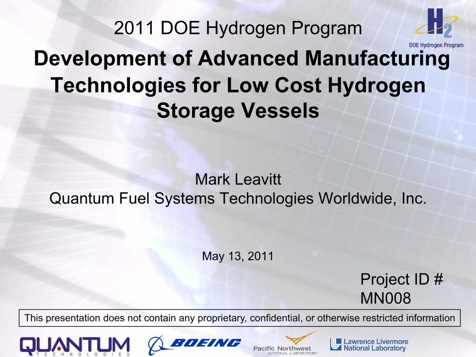
Overview
• Project start date: 09/2008• Project end date: 03/2012• Percent complete: 66%
• High-Cost Carbon Fiber• Lack of Carbon Fiber
Fabrication Techniques for Conformable Tanks
Timeline
Budget
Barriers
• Quantum Technologies, Inc. (QT)
• The Boeing Company (Boeing)• Pacific Northwest National
Laboratory (PNNL)• Lawrence Livermore National
Laboratory (LLNL)
Partners• Total Budget: $5,486,848
DOE Share: $2,566,451QT/Boeing Share: $1,920,397FFRDC Share: $1,000,000
• Funding received in FY10: $400,000
• Funding for FY11: $650,000
3
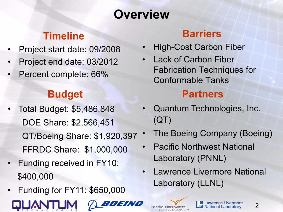
Objectives - RelevanceTo manufacture Type IV H2 storage pressure vessels, utilizing a new hybrid process with the following features:• Optimize elements of advanced fiber placement (AFP) &
commercial filament winding (FW)• Improve understanding of polymer liner H2 degradation
With the aim of addressing the barriers by achieving a manufacturing process with:1. lower composite material usage2. lower cost fiber3. higher manufacturing efficiency
4
Background on Advanced Fiber Placement (AFP) and Why It is Important
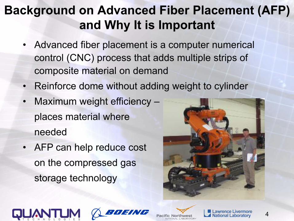
• Advanced fiber placement is a computer numerical control (CNC) process that adds multiple strips of composite material on demand
• Reinforce dome without adding weight to cylinder• Maximum weight efficiency –
places material where needed
• AFP can help reduce coston the compressed gasstorage technology
5
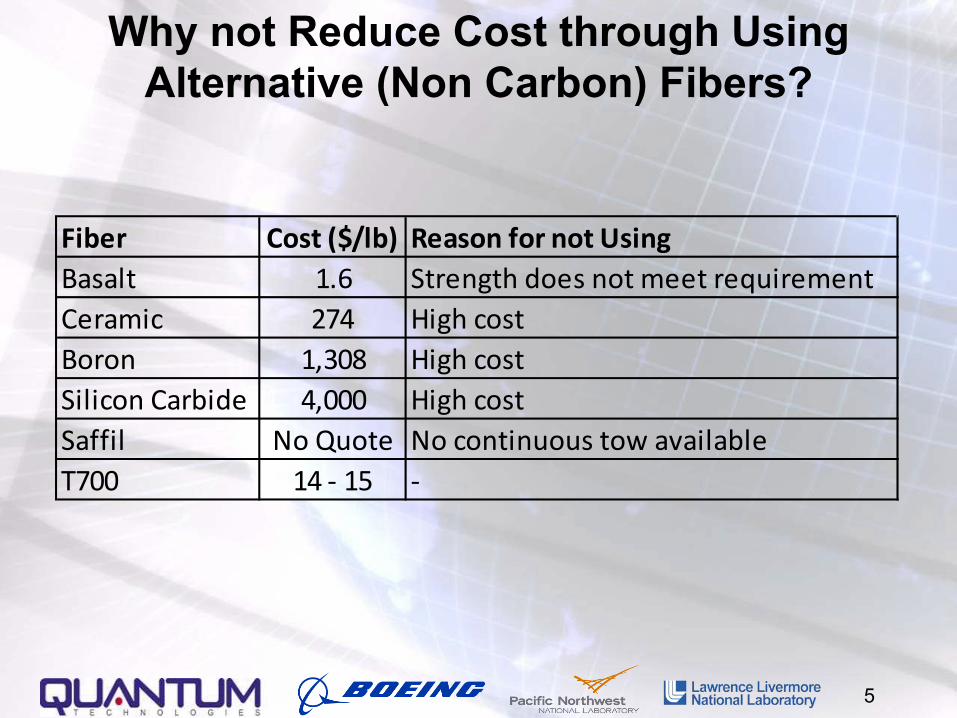
Why not Reduce Cost through Using Alternative (Non Carbon) Fibers?
Fiber Cost ($/lb) Reason for not UsingBasalt 1.6 Strength does not meet requirementCeramic 274 High costBoron 1,308 High costSilicon Carbide 4,000 High costSaffil No Quote No continuous tow availableT700 14 - 15 -
6
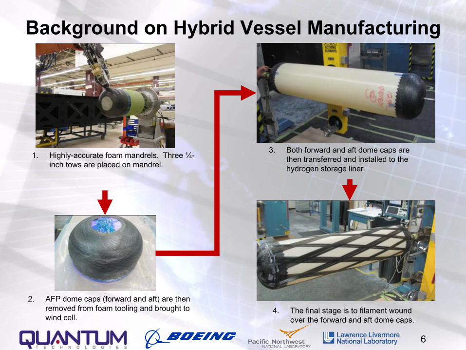
Background on Hybrid Vessel Manufacturing
2. AFP dome caps (forward and aft) are then removed from foam tooling and brought to wind cell.
4. The final stage is to filament wound over the forward and aft dome caps.
1. Highly-accurate foam mandrels. Three ¼-inch tows are placed on mandrel.
3. Both forward and aft dome caps are then transferred and installed to the hydrogen storage liner.
7
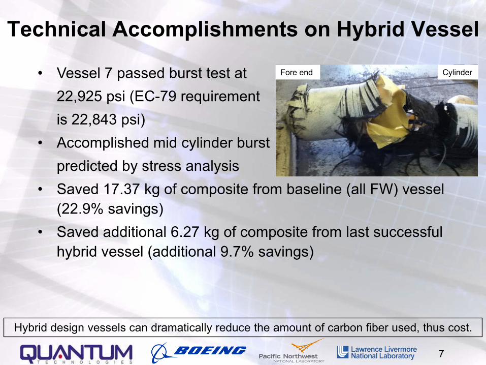
Technical Accomplishments on Hybrid Vessel
• Vessel 7 passed burst test at 22,925 psi (EC-79 requirementis 22,843 psi)
• Accomplished mid cylinder burst predicted by stress analysis
• Saved 17.37 kg of composite from baseline (all FW) vessel (22.9% savings)
• Saved additional 6.27 kg of composite from last successful hybrid vessel (additional 9.7% savings)
Hybrid design vessels can dramatically reduce the amount of carbon fiber used, thus cost.
Fore end Cylinder
8
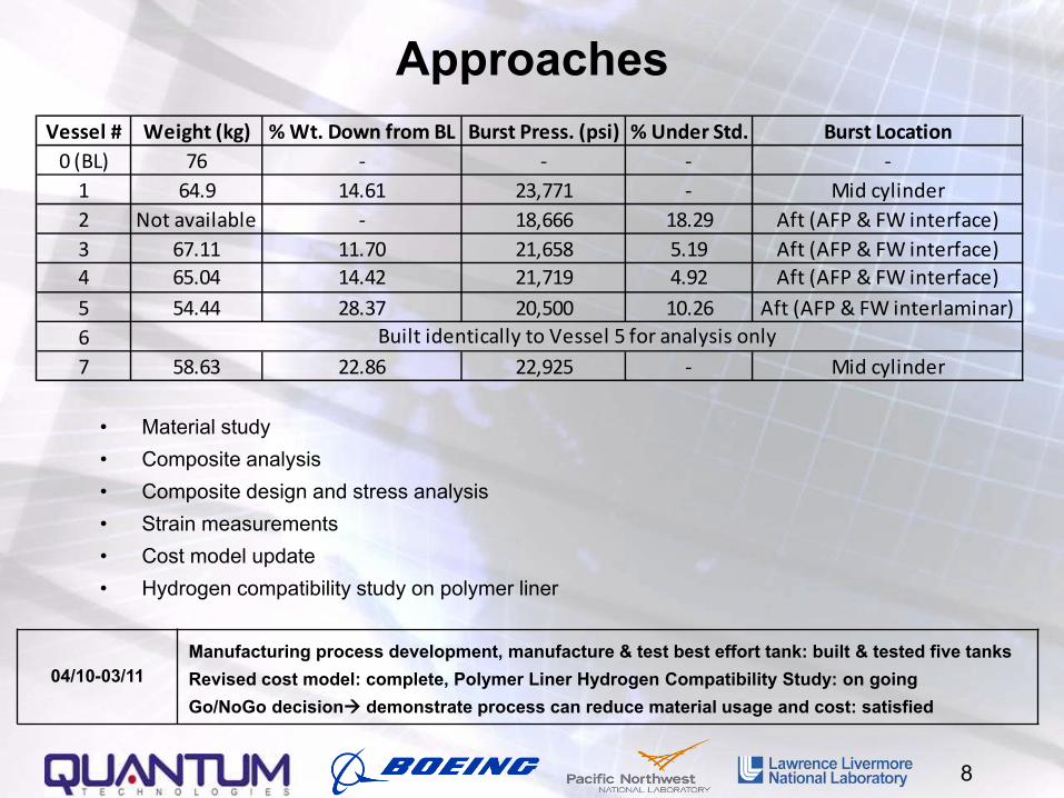
Approaches
• Material study• Composite analysis• Composite design and stress analysis• Strain measurements• Cost model update• Hydrogen compatibility study on polymer liner
04/10-03/11Manufacturing process development, manufacture & test best effort tank: built & tested five tanksRevised cost model: complete, Polymer Liner Hydrogen Compatibility Study: on goingGo/NoGo decision demonstrate process can reduce material usage and cost: satisfied
Vessel # Weight (kg) % Wt. Down from BL Burst Press. (psi) % Under Std. Burst Location0 (BL) 76 - - - -
1 64.9 14.61 23,771 - Mid cylinder2 Not available - 18,666 18.29 Aft (AFP & FW interface)3 67.11 11.70 21,658 5.19 Aft (AFP & FW interface)
5 54.44 28.37 20,500 10.26 Aft (AFP & FW interlaminar)67 58.63 22.86 22,925 - Mid cylinder
Aft (AFP & FW interface)
Built identically to Vessel 5 for analysis only
4 65.04 14.42 21,719 4.92
9
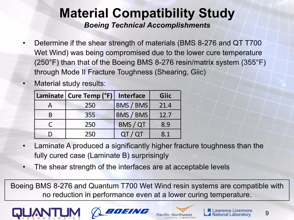
Material Compatibility StudyBoeing Technical Accomplishments
• Determine if the shear strength of materials (BMS 8-276 and QT T700 Wet Wind) was being compromised due to the lower cure temperature (250°F) than that of the Boeing BMS 8-276 resin/matrix system (355°F) through Mode II Fracture Toughness (Shearing, Giic)
• Material study results:
• Laminate A produced a significantly higher fracture toughness than the fully cured case (Laminate B) surprisingly
• The shear strength of the interfaces are at acceptable levels
Boeing BMS 8-276 and Quantum T700 Wet Wind resin systems are compatible with no reduction in performance even at a lower curing temperature.
Laminate Cure Temp (°F) Interface GiicA 250 BMS / BMS 21.4B 355 BMS / BMS 12.7C 250 BMS / QT 8.9D 250 QT / QT 8.1
10
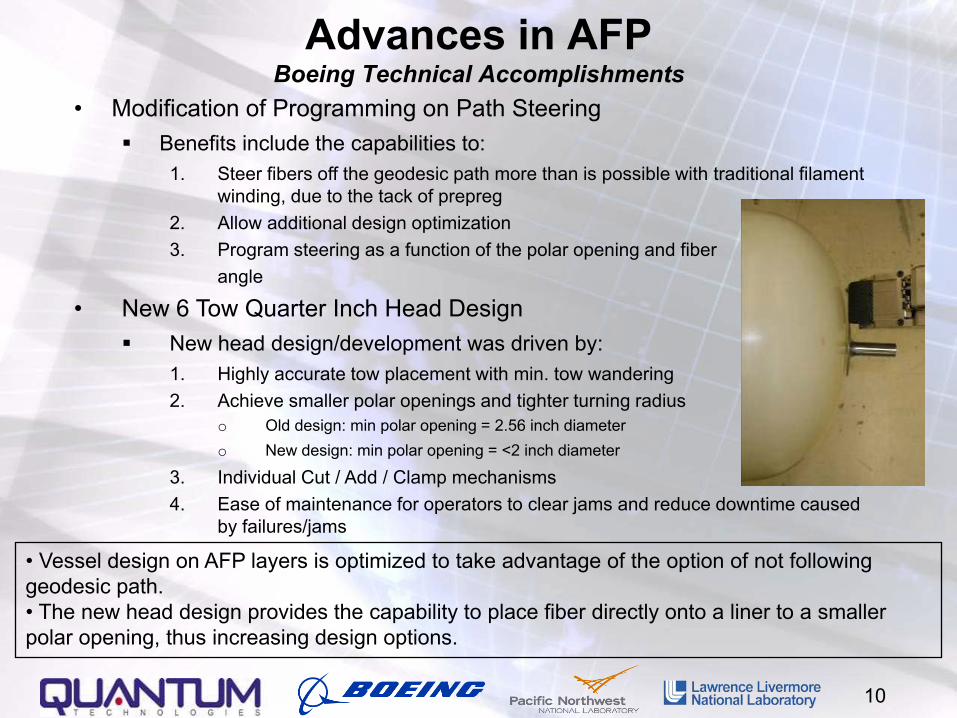
Advances in AFPBoeing Technical Accomplishments
• Modification of Programming on Path Steering Benefits include the capabilities to:
1. Steer fibers off the geodesic path more than is possible with traditional filament winding, due to the tack of prepreg
2. Allow additional design optimization3. Program steering as a function of the polar opening and fiber
angle
• New 6 Tow Quarter Inch Head Design New head design/development was driven by:
1. Highly accurate tow placement with min. tow wandering2. Achieve smaller polar openings and tighter turning radius
o Old design: min polar opening = 2.56 inch diametero New design: min polar opening = <2 inch diameter
3. Individual Cut / Add / Clamp mechanisms4. Ease of maintenance for operators to clear jams and reduce downtime caused
by failures/jams
• Vessel design on AFP layers is optimized to take advantage of the option of not following geodesic path.• The new head design provides the capability to place fiber directly onto a liner to a smaller polar opening, thus increasing design options.
11
Composite AnalysisApproaches
• Cross Sectional Photomicrograph by Boeing Photographed samples from a vessel that did not pass burst
test in both longitudinal and circumferential directions
• Short Beam Shear Testing by Quantum Performed tests according to ASTM D 2344/D 2344M with
samples from a vessel that was manufactured for analysis only (no burst test prior)
• Composite Build up Analysis by Quantum Measured and compared the actual vs. assumed necking
value on both the fore and aft ends
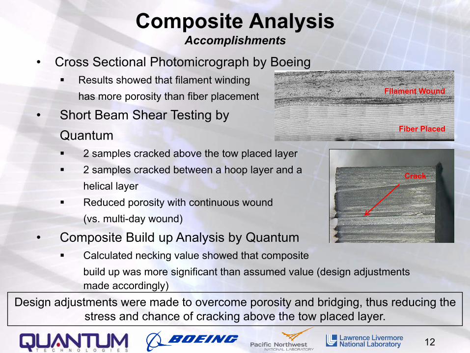
• Cross Sectional Photomicrograph by Boeing Results showed that filament winding
has more porosity than fiber placement
• Short Beam Shear Testing by Quantum 2 samples cracked above the tow placed layer 2 samples cracked between a hoop layer and a
helical layer Reduced porosity with continuous wound
(vs. multi-day wound)
• Composite Build up Analysis by Quantum Calculated necking value showed that composite
build up was more significant than assumed value (design adjustments made accordingly)
12
Design adjustments were made to overcome porosity and bridging, thus reducing the stress and chance of cracking above the tow placed layer.
Filament Wound
Fiber Placed
Crack
Composite AnalysisAccomplishments
13
• Composite Design Design for mid cylinder burst with a safety factor of 2.25 Minimize bridging and voids
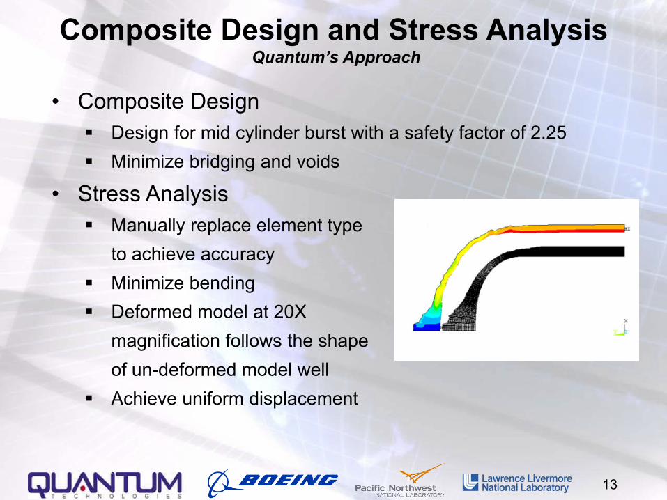
• Stress Analysis Manually replace element type
to achieve accuracy Minimize bending Deformed model at 20X
magnification follows the shape of un-deformed model well
Achieve uniform displacement
Composite Design and Stress Analysis Quantum’s Approach
14
Strain MeasurementsApproaches
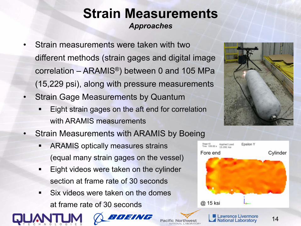
• Strain measurements were taken with two different methods (strain gages and digital imagecorrelation – ARAMIS®) between 0 and 105 MPa (15,229 psi), along with pressure measurements
• Strain Gage Measurements by Quantum Eight strain gages on the aft end for correlation
with ARAMIS measurements
• Strain Measurements with ARAMIS by Boeing ARAMIS optically measures strains
(equal many strain gages on the vessel) Eight videos were taken on the cylinder
section at frame rate of 30 seconds Six videos were taken on the domes
at frame rate of 30 seconds
CylinderFore end
@ 15 ksi
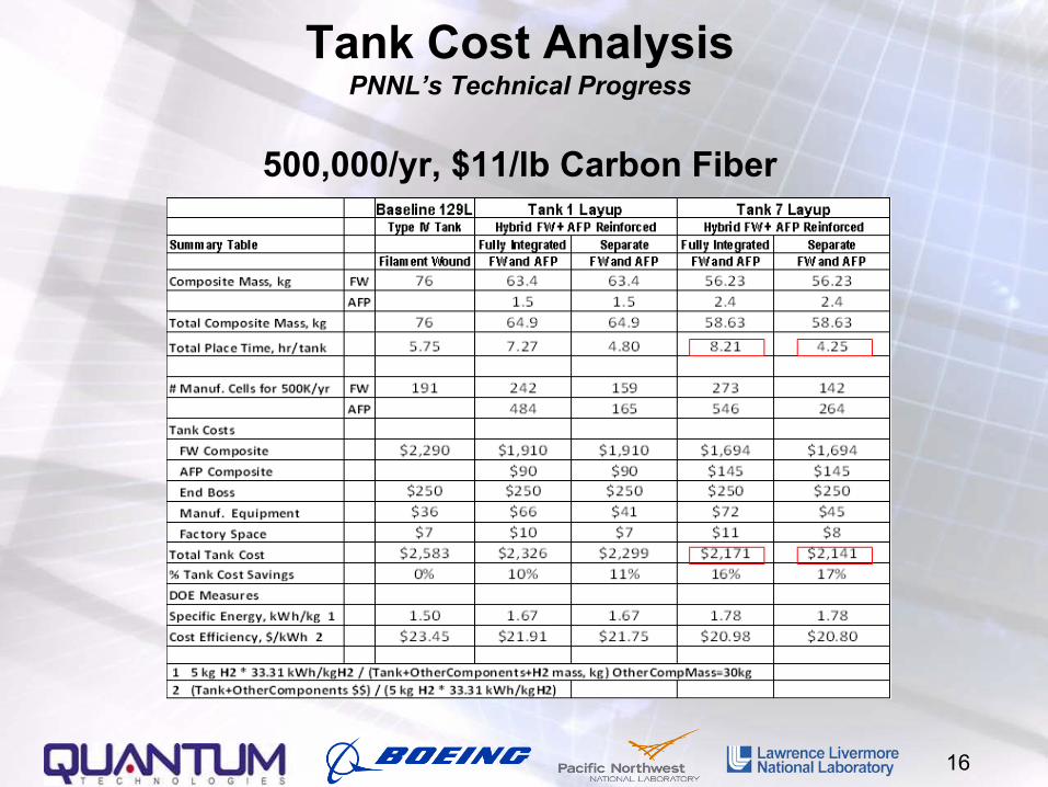
Tank Cost AnalysisPNNL’s Approach
15
• Quantum and Boeing’s experience provided $/kg of FW and AFP composites
• Hybrid composite design provided the mass of FW and AFP composites• Cost model included materials, labor, overhead, balance of system,
manufacturing equipment, and factory space costs• Baseline and two bounding manufacturing scenarios were investigated:
1. Baseline = Quantum Filament Wound 129 Liter, Type IV Tank2. Fully Integrated FW and AFP – Composite layup optimized for high
strength, but inefficient machine usage3. Fully Separate FW and AFP – 100% machine usage, and able to meet
design requirements by success of Vessel 7FY11 - Cost Model updated to compare Vessel 1 and 7 layup designs with
the baseline FW vessel
16
Tank Cost AnalysisPNNL’s Technical Progress
500,000/yr, $11/lb Carbon Fiber
17
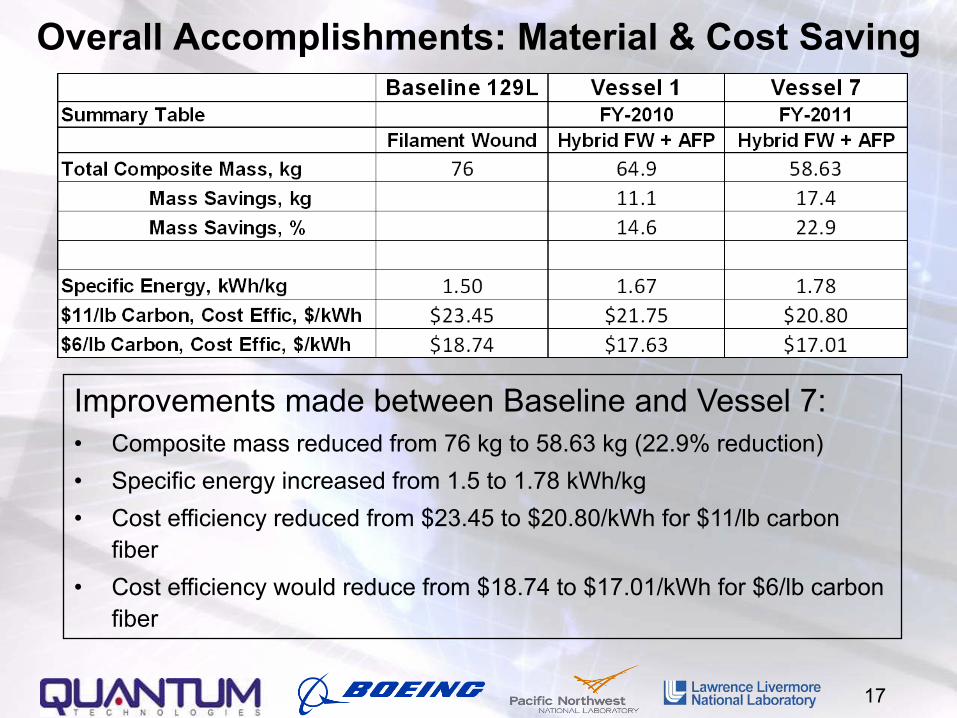
Overall Accomplishments: Material & Cost Saving
Improvements made between Baseline and Vessel 7:• Composite mass reduced from 76 kg to 58.63 kg (22.9% reduction)• Specific energy increased from 1.5 to 1.78 kWh/kg• Cost efficiency reduced from $23.45 to $20.80/kWh for $11/lb carbon
fiber• Cost efficiency would reduce from $18.74 to $17.01/kWh for $6/lb carbon
fiber
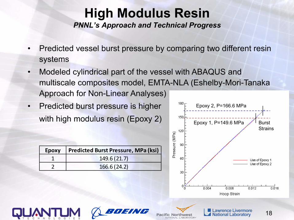
High Modulus ResinPNNL’s Approach and Technical Progress
18
• Predicted vessel burst pressure by comparing two different resin systems
• Modeled cylindrical part of the vessel with ABAQUS and multiscale composites model, EMTA-NLA (Eshelby-Mori-Tanaka Approach for Non-Linear Analyses)
• Predicted burst pressure is higherwith high modulus resin (Epoxy 2)
Epoxy 2, P=166.6 MPa
Epoxy 1, P=149.6 MPa BurstStrains
Epoxy Predicted Burst Pressure, MPa (ksi)1 149.6 (21.7)2 166.6 (24.2)
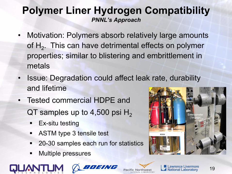
Polymer Liner Hydrogen CompatibilityPNNL’s Approach
• Motivation: Polymers absorb relatively large amounts of H2. This can have detrimental effects on polymer properties; similar to blistering and embrittlement in metals
• Issue: Degradation could affect leak rate, durability and lifetime
• Tested commercial HDPE and QT samples up to 4,500 psi H2 Ex-situ testing ASTM type 3 tensile test 20-30 samples each run for statistics Multiple pressures
19
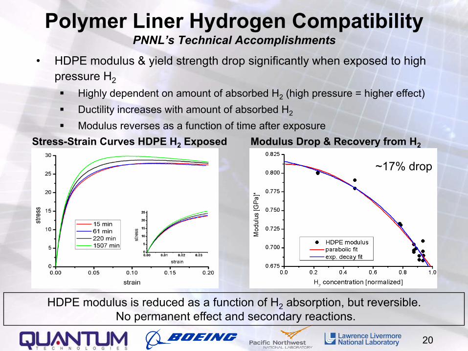
• HDPE modulus & yield strength drop significantly when exposed to high pressure H2
Highly dependent on amount of absorbed H2 (high pressure = higher effect) Ductility increases with amount of absorbed H2
Modulus reverses as a function of time after exposureStress-Strain Curves HDPE H2 Exposed Modulus Drop & Recovery from H2
~17% drop
Polymer Liner Hydrogen CompatibilityPNNL’s Technical Accomplishments
HDPE modulus is reduced as a function of H2 absorption, but reversible. No permanent effect and secondary reactions.
20
21
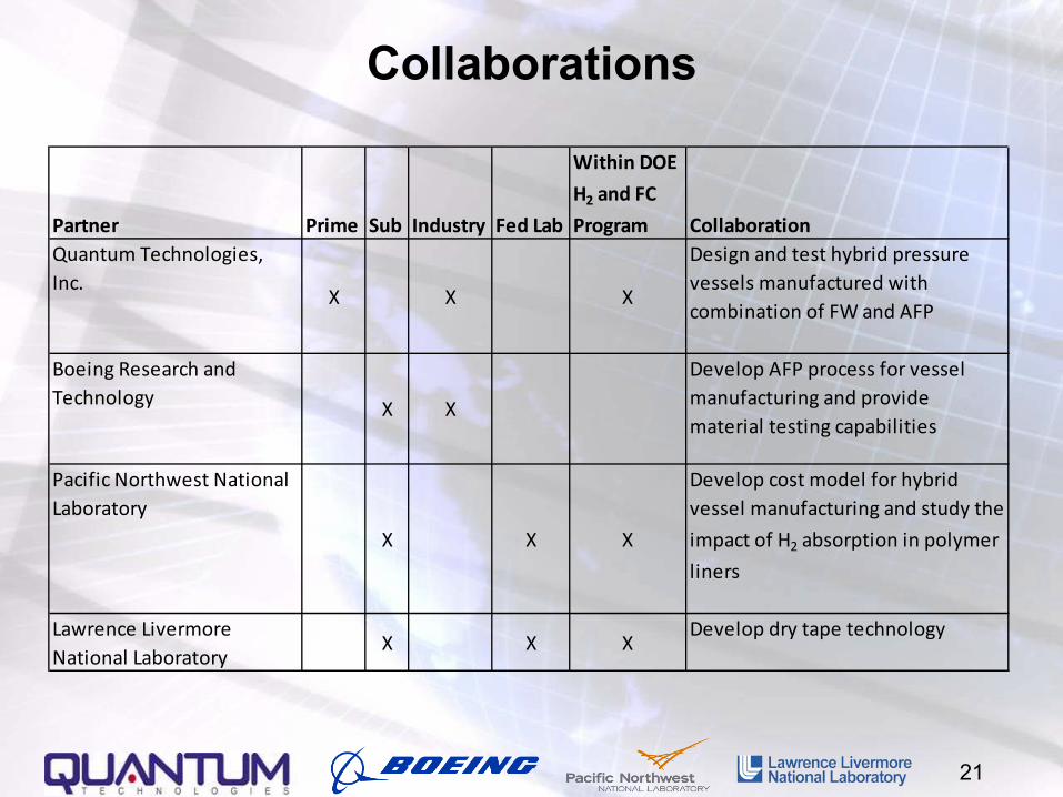
Collaborations
Partner Prime Sub Industry Fed Lab
Within DOE
H2 and FC
Program CollaborationQuantum Technologies, Inc.
X X X
Design and test hybrid pressure vessels manufactured with combination of FW and AFP
Boeing Research and Technology X X
Develop AFP process for vessel manufacturing and provide material testing capabilities
Pacific Northwest National Laboratory
X X X
Develop cost model for hybrid vessel manufacturing and study the
impact of H2 absorption in polymer
liners
Lawrence Livermore National Laboratory
X X XDevelop dry tape technology
22
Proposed Future Work: Strategies for Program Goals
FY11• Evaluate the application of lower cost carbon fiber on the outer
layers of filament winding to further reduce cost• Test vessels with lower cost fiber per EC-79
Ambient temperature burst test Ambient temperature cycle test
• Complete H2 tensile tests on HDPE & other relevant materialsFY12• Testing to national standards on critical tests that might be
affected by AFP/FW hybrid process Extreme temperature cycle test Accelerated stress rupture
• Developing in-situ tensile test rig for high pressure H2
• Build and test a tank with higher modulus resin• Update cost model to include the consideration of lower
performance carbon fiber
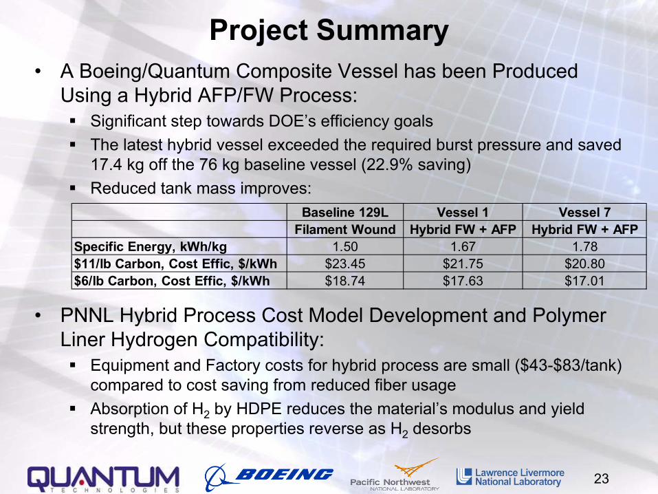
Project Summary• A Boeing/Quantum Composite Vessel has been Produced
Using a Hybrid AFP/FW Process: Significant step towards DOE’s efficiency goals The latest hybrid vessel exceeded the required burst pressure and saved
17.4 kg off the 76 kg baseline vessel (22.9% saving) Reduced tank mass improves:
• PNNL Hybrid Process Cost Model Development and Polymer Liner Hydrogen Compatibility: Equipment and Factory costs for hybrid process are small ($43-$83/tank)
compared to cost saving from reduced fiber usage Absorption of H2 by HDPE reduces the material’s modulus and yield
strength, but these properties reverse as H2 desorbs
23
Baseline 129L Vessel 1 Vessel 7Filament Wound Hybrid FW + AFP Hybrid FW + AFP
Specific Energy, kWh/kg 1.50 1.67 1.78$11/lb Carbon, Cost Effic, $/kWh $23.45 $21.75 $20.80$6/lb Carbon, Cost Effic, $/kWh $18.74 $17.63 $17.01
Technical Back-Up Slides
24
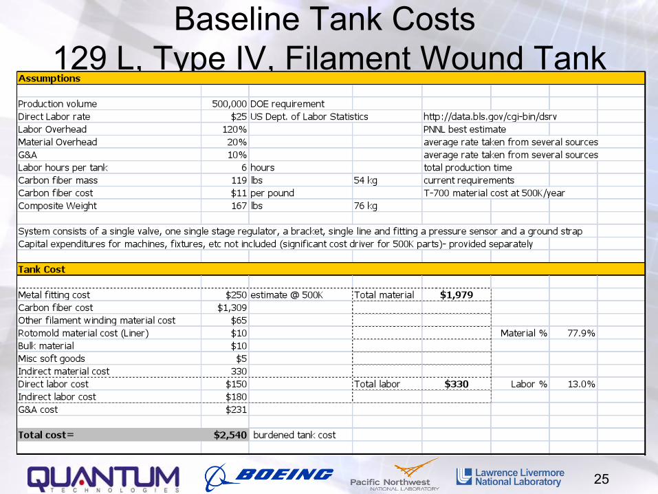
Baseline Tank Costs 129 L, Type IV, Filament Wound Tank
25
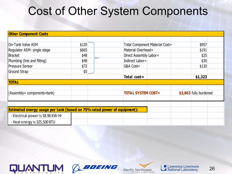
Cost of Other System Components
26
Other Component Costs
On-Tank Valve ASM $120 Total Component Material Cost= $957Regulator ASM- single stage $665 Material Overhead= $191Bracket $48 Direct Assembly Labor= $25Plumbing (line and fitting) $48 Indirect Labor= $30Pressure Sensor $72 G&A Cost= $120Ground Strap $5
Total cost= $1,323TOTAL
(Assembly= components+tank) TOTAL SYSTEM COST= $3,863 fully burdened
Estimated energy usage per tank (based on 75% rated power of equipment): - Electrical power is 58.96 KW-Hr - Heat energy is 325,500 BTU
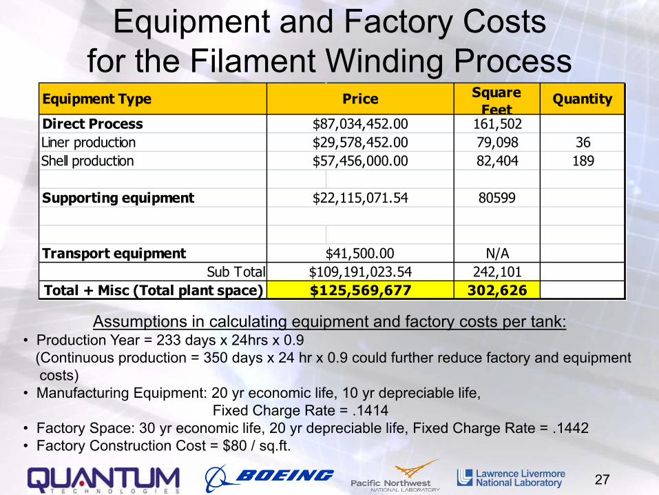
Equipment and Factory Costsfor the Filament Winding Process
27
Direct Process 161,502Liner production 79,098 36Shell production 82,404 189
Supporting equipment 80599
Transport equipment N/ASub Total 242,101
Total + Misc (Total plant space) 302,626$109,191,023.54$125,569,677
$87,034,452.00$29,578,452.00$57,456,000.00
$22,115,071.54
$41,500.00
Equipment Type Price Square Feet
Quantity
Assumptions in calculating equipment and factory costs per tank:• Production Year = 233 days x 24hrs x 0.9
(Continuous production = 350 days x 24 hr x 0.9 could further reduce factory and equipmentcosts)
• Manufacturing Equipment: 20 yr economic life, 10 yr depreciable life, Fixed Charge Rate = .1414
• Factory Space: 30 yr economic life, 20 yr depreciable life, Fixed Charge Rate = .1442• Factory Construction Cost = $80 / sq.ft.
• Boeing Estimates AFP Material = $28/lb, assuming the high volume
cost is twice the as-formed cost of FW composite, $14/lb
AFP Factory Space = 203 sq.ft. per machine
28
Material and Factory Costsfor the AFP Process
Recommended