2010 IEEE EMBS Conference on Biomedical Engineering & Sciences (IECBES 2010), Kuala Lumpur, Malaysia, 30th November - 2nd December 2010.
Development of a Low-Cost and Portable Device Controller for Point-of-Care Medical Diagnostics
Peyman lahanshahi Dept. of Electrical Engineering,
Faculty of Engineering, University of Malaya, Kuala Lumpur, Malaysia [email protected]
Siti Zawiah Md Dawal Dept. of Eng. Design and Manufacture,
Faculty of Engineering, University of Malaya, Kuala Lumpur, Malaysia
Fatimah Ibrahim Dept. of Biomedical Engineering,
Faculty of Engineering, University of Malaya, Kuala Lumpur, Malaysia
Abstract- The field of centrifugal microfluidics aims to
miniaturize common biochemical assays onto specialized discs
(CDs), By the exploitation of the centrifugal force, centrifugal
microfluidics CDs do not require the syringe pumps that
stationary micl"Ofluidic platforms I'equil'e, This papel' describes
the development of a low-cost and portable controller device that
is capable of perfol'ming centrifugal microfluidics at the point-of
care (POC), Overall, this system aims to be low in cost, fast, and
modulal',
In this study, the Spin-Stand device controller is the final
product of three stages of development: design, virtual
simulation and implementation, At the core of the system, the
contl"OlIer is designed to adjust the disc rotational speed fOl' performing several operations by Pulse Width Modulation
(PWM) through PIC (Pl"Ogl'ammable [ntel'face Controller),
Keywords- Lab-On-Disc, Point-Of-Care, PIC microcontroller,
Portable Device, Spin-Stand Device, Microfluidic Disc,
I. INTRODUCTION
Microfluidics aims to miniaturize the diagnostic power of a complete laboratory to create portable and disposable diagnostic devices. These tools are being developed as micro total analysis systems (�T AS) where several steps involved in sample preparation and disease detection are integrated onto a single device [I].
Such devices would bring diagnostics to the point-of-care where the treatment is administered [2]. Ideally microfluidic devices would be low in cost, operate automatically, and have low power requirements so that they can be used in low-infrastructure settings. Therefore, there is an obvious and urgent need to develop such a technology.
Centrifugal microfluidics, or microfluidic CDs, is a unique approach to the field of micro fluidics where fluids are manipulated within specialized CDs by rotation. By exploiting the centrifugal
Ali A, Nozari Dept. of Mechanical Engineering,
Faculty of Engineering, University of Malaya, Kuala Lumpur, Malaysia
Norhayati Soin Dept. of Electrical Engineering,
Faculty of Engineering, University of Malaya, Kuala Lumpur, Malaysia
force, liquids are moved to the outer rim of the disc, eliminating the need for bulky and complex syringe pumps that stationary microfluidic chips require. In addition, in conventional stationary microfluidic chips experiments are accomplished by tedious manual intervention and expensive interconnects, creating neither a platfornl that is neither automated nor easy to use [3].
Centrifugal microfluidic discs emerged the 1960's in an effort to automate and perform parallel biochemical reactions on specialized fluidic discs. In the past decade the field of centrifugal microfluidics has been heavily revisited by several groups internationally (Dr. Marc Madou, USA; Dr. Jen Ducree, Ireland; Dr. Cho, Korea) [4,5]. While these groups have advanced the platfornl significantly, a significant problem remains: while the disc has always been portable, the supporting hardware (i.e. spin-stand, optical visualization equipment) has not been. The problem has arisen where this microfluidic discs are "chips in a lab" instead of being a "labs on a chip". This paper presents a low-cost portable device controller for point-of-care medical diagnostic applications.
II. BACKGROUND
In microfluidic discs, the rotational speed should be determined from derived fluid mechanics equations to move liquid from one point to another in a microchannel. The most basic and common form of valving on the microfluidic CD platform is capillary valving, This type of valving requires no moving mechanical parts, rather is based on holding the fluid back due to the capillary pressure generated when a small volume of liquid is forced through a constriction (i.e., a microchannel) [6]. Liquid will hold at that microchannel as long as the capillary pressure is not broken, and can be broken by applying an external force to the liquid. In centrifugal microfluidic discs, this force is the centrifugal force and liquid will break into a microchannel once the applied centri fugal force is larger than that of the capillary pressure holding the liquid back [7,8].
One application for a Spin-Stand device is for the separation of plasma from whole blood, a sample preparation step common to many biochemical diagnostic assays [9, I 0, 11]. This will be discussed
978-1-4244-7600-8/10/$26.00 ©201 0 IEEE 450
below. The system can control the lab on a disc automatically without the need for an operator. The disc spin stand has been designed in an international standard size of 12 cm disc.
There are several variables that must be considered when designing a controller spin-stand that performs centrifugal microfluidics: motor tolerance in rotational speed, effects of vibrational noise on the fluidics, motor acceleration and deceleration rates, motor controlling mechanisms, and motor reaction time.
III. METHODS & MATERIALS
The development of a portable disc spin-stand controller system geared micro fluidic disc applications included: designing of electronic circuits, choosing suitable mechanical and electrical
components, writing source codes in Micro Code studio software, simulating the circuit design by Proteus software, actuating the control motor by a microcontroller, and fabricating a suitable PCB board.
A. Design
The developed system has two main parts: a specialized spinstand and a controller unit. The system is equipped with a lens that connects to a camera. The specialized spin-stand is made of Teflon chassis which includes several parts inside: a BLDC servo-motor for spinning microfluidic discs, a fan for cooling, supporting electronic connectors to integrate electronics, and a COM port that connects to the control unit.
The controller unit consists of a keypad to give the user an interface to apply appropriate rotational speeds to the microfluidics discs, an Liquid Crystal Display (LCD) 16 Character x 2 Line that displays the rotational speed, a switch to change rotational direction (clockwise, counter clockwise), and a COM port that communicates with the spin-stand. Also within the unit is a PIC l6F877a microcontroller that controls the motor. The controller is designed to adjust the disc rotational speed for performing several operations by Pulse Width Modulation (PWM).
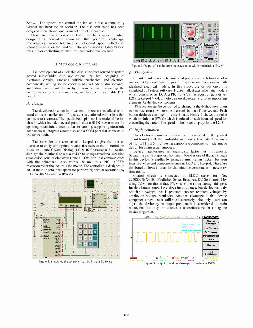
Figure I. Simulated the control circuit by Proteus Software
451
Figure 2. Output of oscilloscope indicates pulse width modulation (PWM)
B. Simulation
Circuit simulation is a technique of predicting the behaviour of a
real circuit by a computer program. It replaces real components with idealized electrical models. In this study, the control circuit is simulated by Proteus software. Figure I illustrates schematic models which consist of an LCD, a PIC l6F877a microcontroller, a driver L298, a keypad 4 x 4, a motor, an oscilloscope, and some supporting elements for driving components.
This system can be controlled to change to the desired revolution per minute (rpm) by pressing the each button of the keypad. Each button declares each step of experiments. Figure 2 shows the pulse width modulation (PWM) which is related to each intended speed for controlling the motor. The speed of the motor displays by the LCD.
C. implementation
The electronic components have been connected to the printed circuit board (PCB) that embedded in a plastic box with dimensions of 16cm x 11 em X 5cm • Choosing appropriate components made unique design for commercial purposes.
Device maintenance is significant factor for instruments. Separating each component from main board is one of the advantages in this device. It applies by using communication sockets between interface wires and components such as LCD and Keypad. Therefore this benefit allows to users for changing the components in necessary time easily.
Control circuit is connected to BLOC servomotor (No. 2250S024BX4 SC, Faulhaber Series Brushless DC Servomotor) by using COM port that in fact, PWM is sent to motor through this port. Inside of main board have three input voltage, but device has only one input voltage that it produces another required voltages by employing voltage regulators. Another advantage is that device components have been calibrated separately. Not only users can adjust the device by an output port that it is considered on main board, but also they can connect it to oscilloscope for tuning the device (Figure 3).
"!'Ba 13: -Aug� 10 11: 413 Tr
Dest� i nat.. i on USB
Save Image
Ink Saver
1J1JlOO[ ��" Save
File Utilities
_ • . CH1 EDGE ./ Itt..1: 11::.1H. CH 1 5V CH2 .rl? SU CH3 = seefl'lu (� )\::
Figure 3. Output of real oscilloscope that indicates PWM

Figure 4. Spin-Stand controlling Device, BIOMEMS Lab,
University of Malaya.
Apart from previous advantages, the device is programmable.
Basically user can change all definitions of the keypad buttons. Each experiment has specific speeds and incubation times for their each steps, therefore the device is designed so that can be flexible for various assays that programming port is embedded on the main board.
The system is equipped to spinning direction switch that if LCD is in front of user, it can be touched in left side of the box as shown in Figure 4.
I V . RESULTS AND DISCUSSION
The complete setup of the spin-stand device is as shown in Figure 5. The portable spin-stand controller has been tested on an application of plasma separation. The plasma separation disc has been designed and fabricated on Polymethyl methacrylate (PMMA) disc. This design was adapted from reference [9].
As shown in Figure 6, a blood sample of 100 IlLiter has been
injected into chamber I. The controller has been assigned to 3600 rpm clockwise (C.W.) for 120 seconds and then the motor direction was changed to counter clock wise (C.C.W.) for 20s at 2400 rpm. The spin-stand device can be stopped after passing these steps. All sequences have been specified as table I. The separation of plasma can be occurring at several speed ranges. It is obviously its time and
rpm will be specified by having another burst frequencies of each valve in the Lab-On-Disc.
At the end of experiment, the red blood cells (RBCs) will be accumulated at chamber 2, while the plasma is at chamber 3. This structure of extracting plasma is designed to achieved plasma of 50 IlLiter will be extracted in chamber 3. After each experiment, the results will be observed by using the Microscope.
The blood separation part can help to extract the plasma automatically and be used in diverse assays such as ELISA, DNA Hybridization, etc.
This device is beneficial for attending clinician especially in resource poor settings to make the best clinical management decision.
In fact, the field of micro fluidics aims to miniaturize laboratory processes to create portable diagnostic devices.
Figure 6. Blood Separation Disc, designed in BIOMEMS Lab, University of
Malaya.
One of advantages of disc system is reduction of the required electrical power. The power consumption decreases with reduction in the size and weight of system and the materials used. The disc spin stand system has the advantage of being locally fabricated, with an
automatic disc controller, and is portable and low-cost. It can be a local Malaysian product since the design has been developed locally
according to the requirements and specifications that function for disc spin stand system. Other benefits of spin base device are as follows:
The benefits of this device are utilization of inexpensive components, easy to operate, require user input and easy to use in a wide variety of climate conditions.
Beside declared advantages, this device has easy portability. As a matter of fact it can work by battery, so it can be portable and has
minimal power requirements for accomplishing each biomedical assay because of unique design.
Moreover, it is adaptable for many other medical laboratory diagnostic applications.
452

Table I. Sequences of extracting plasma
No. of Description of Suggested Volume Suggested chambers chambers Time(s) (l-lLiter) Rotation
speed (rpm)
I Whole blood 120 100 3600
(sample) CW.
2 Storage 2400 Sedimentatio 20 45
C.CW n (RBCs)
3 Plasma 0 50 0
V. CONCLUSIONS
This report successfully demonstrated a spin-stand controller that is low-cost, portable, and optimized for use at the point-of-care for plasma separation. Because of the programmability of the proposed device, unique spin-profiles can be progranuned by the user to perform a particular assay (e.g., ELISA for any infectious diseases and peR) automatically. Since the system uses of off-the-shelf, the device as a whole is suitable for commercialization. It is envisioned that the proposed device can be used for later clinical testing to
determine both the performance and efficacy of the new technology. After such testing, the device would then be used by health care professionals in clinical settings (a traditional doctor's offices or in a remote setting with low-infrastructure) to perform centrifugal microfluidics.
ACKNOWLEDGMENT
This research was supported in part by University Malaya Research Grant (UMRG, Project No. : RG023/09AET), Fundamental Research Grant Scheme (FRGS, Project No.: FP059/2010A) and
Sultan Iskandar Johor Foundation.
REFERENCES
[I] M. Madou, J. Zoval, G. Jia, H. Kido, J. Kim, and N. Kim, "Lab on a CD," 2006.
[2] P. Yager, GJ. Domingo, and J. Gerdes, "Point-of-care diagnostics for global health.," Annual review of biomedical engineering, vol. 10,2008, pp. 107-44.
[3] E.a. Hunsperger, S. Yoksan, P. Buchy, V.c. Nguyen, S.D. Sekaran, D.a. Enria, J.L. Pelegrino, S. Vazquez, H. Artsob, M. Drebot, DJ. Gubler, S.B. Halstead, M.G. Guzman, H.S. Margolis, C. Nathanson, N.R. Rizzo Lic, K.E. Bessoff, S. Kliks, and R.W. Peeling, "Evaluation of commercially available anti-dengue virus immunoglobul in M tests.," Emerging infectious diseases, vol. 15,
2009, pp. 436-40.
[4] R. Gorkin, J. Park, J. Siegrist, M. Amasia, B.S. Lee, J. Park, J. Kim, H. Kim, M. Madou, and Y. Cho, "Centrifugal microtluidics for biomedical applications.," Lab on a chip, 20 I 0, pp. 1758-I 773.
[5] R. Zengerle, P. Koltay, and J. Ducree, "Microtluidics: an enabling technology for the life sciences," Micro-Nanomechatronics and
[6]
[7]
[8]
[9]
[10]
[II]
453
Human Science, 2004 and The Fourth Symposium Micro
Nanomechatronics for Information-Based Society, 2004., pp. 1-6.
H. He, Y. Yuan, W. Wang, N. Chiou, AJ. Epstein, and LJ. Lee, "Design and testing of a microtluidic biochip for cytokine enzymelinked immunosorbent assay.," Biomicrojluidics, vol. 3, 2009, p. 22401.
J. Peyman, a.A. Nozari, N. Soin, and F. Ibrahim, "Evaluation of pressure changes for Capillary and Fishbone valves in Lab-on-CD systems," 2009 International Conference for Technical Postgraduates (TECHPOS), 2009, pp. 1-5.
H. Cho, H. Kim, J.Y. Kang, and T.S. Kim, "How the capillary burst microvalve works.," Journal of colloid and intelface science,
voL 306,2007, pp. 379-85.
B.S. Lee, J. Lee, J. Park, J. Lee, S. Kim, Y. Cho, and C. Ko, "A fully automated immunoassay from whole blood on a disc.," Lab on a chip, voL 9, 2009, pp. 1548-55.
B.S. Lee, J. Lee, J. Lee, J. Park, Y. Cho, S. Kim, and C. Ko, "Onestep Target Protein Detection from Whole Blood in a Lab-on-aDisc Protein Conjugation on Microbead," vol. 3,2008, pp. 241-
244.
A. Wissenschaften and B. Freiburg, "Thilo Brenner Polymer Fabrication and Microtluidic Unit Operations for Medical Diagnostics on a Rotating Disk," 2005.
Recommended