DESIGNING AND MANUFACTURE SOLAR TURBINE
MOHAMAD YAZID BIN MOHAMAD YASSIN
Report submitted in partial fulfillment of the requirements for the award of
Diploma in Mechanical Engineering
Faculty of Mechanical Engineering
UNIVERSITI MALAYSIA PAHANG
NOVEMBER 2010
1
SUPERVISOR’S DECLARATION
I hereby declare that I have checked this project report and in my opinion this project is
satisfactory in terms of scope and quality for the award of Diploma in Mechanical
Engineering.
Signature:
Name of Supervisor:
Position:
Date:
2
STUDENT DECLARATION
I hereby declare that the work in this report is my own except for quotations and
summaries which have been duly acknowledged. The report has not been accepted for
any degree and is not concurently submitted for award of other degree.
Signature:
Name:
ID Number:
Date:

3
ACKNOWLEDGEMENT
Praise to God for His help and guidance that I am able to complete the task of the
Final Year Project. I am thankful and grateful to my supervisor, Mr Idris Bin Mat Sahat
for his advice and knowledge that he shared in the completion of the project. I appreciate
his help for me while I am doing the Final Year Project from week 1 to the day I
finished my Final Year Project.
I also would like to thank all my friends who have been really helpful during the
course of the conducting the Final Year Project. I also would like to thank laboratory
assistants who have help me in sharing knowledge in conjunction with the project that I
am conducting.
I sincerely grateful to my parents for they love and sacrifice that they had for me
throughout my life and their support for me in all my activities that I have done. I also
wanted to that other people who have directly or indirectly help in the completion of my
Final Year Project. I sincerely appreciate all your help.
4
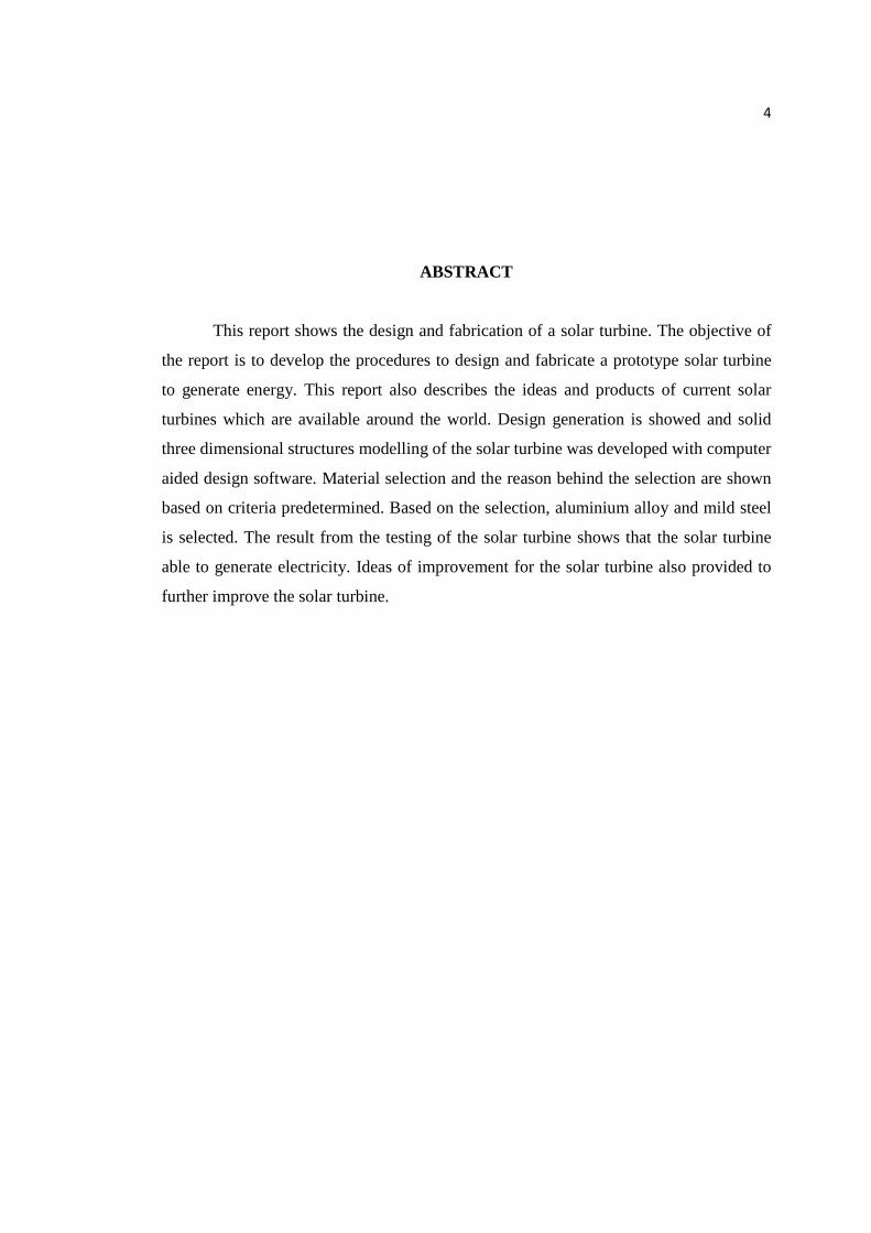
ABSTRACT
This report shows the design and fabrication of a solar turbine. The objective of
the report is to develop the procedures to design and fabricate a prototype solar turbine
to generate energy. This report also describes the ideas and products of current solar
turbines which are available around the world. Design generation is showed and solid
three dimensional structures modelling of the solar turbine was developed with computer
aided design software. Material selection and the reason behind the selection are shown
based on criteria predetermined. Based on the selection, aluminium alloy and mild steel
is selected. The result from the testing of the solar turbine shows that the solar turbine
able to generate electricity. Ideas of improvement for the solar turbine also provided to
further improve the solar turbine.
5
ABSTRAK
Laporan ini menunjukkan lukisan dan pembuatan turbin solar. Objectif untuk
laporan ini adalah untuk menghasilkan prosedur-prosedur untuk menghasilkan lukisan
dan pembuatan prototaip turbin solar yang menjana tenaga. Laporan ini juga
menerangkan tentang idea-idea dan produk-produk turbin solar yang terdapat di serata
dunia. Generasi lukisan telah ditunjukkan dan permodelan struktur-struktur pejal tiga
dimensi untuk turbin solar telah dihasilkan menggunakan perisian lukisan bantuan
komputer. Pemilihan material dan seba-sebab pemilihan telah ditunjukkan berdasarkan
criteria yang telah ditetapkan. Berdasarkan pemilihan tersebut, aluminium aloi dan
logam asli telah dipilih. Keputusan daripada percubaan turbin solar tersebut
menunjukkan ia mampu menjana tenaga elektrik. Idea-idea pembaikan untuk turbin
solar juga diberi untuk improvasi turbin solar tersebut.
6
TABLE OF CONTENTS
Page
SUPERVISOR’S DECLARATION ii
STUDENT’S DECLARATION iii
ACKNOWLEDGEMENTS iv
ABSTRACT v
ABSTRAK vi
TABLE OF CONTENTS vii
LIST OF TABLES x
LIST OF FIGURES xi
CHAPTER 1 INTRODUCTION 1
1.1 Introduction
1.2 Project Background 1
1.3 Problem Statement 2
1.4 Project Objective 2
1.5 Project Scope 2
1.6 Gantt Chart 3
1.7 Flow Chart 4
CHAPTER 2 LITERATURE REVIEW 5
2.1 Literature Review 5
2.1.1 Solar Turbine 1 5 2.1.2 Solar Turbine 2 7 2.1.3 Solar Turbine 3 8 2.1.4 Solar Turbine 4 10
7
CHAPTER 3 METHODOLOGY 12
3.1 Design Generation 12
3.1.1 Sketch 1 12 3.1.2 Sketch 2 13 3.1.3 Sketch 3 13 3.1.4 Sketch 4 14
3.2 Finalize Design 15
3.3 Bill of Materials 19
3.4 Fabrication 19
3.4.1 Cutting 20 3.4.2 Bending 21 3.4.3 Drilling 21 3.4.4 Riveting 22 3.4.5 Surface Finish 22 3.4.6 Project Testing 23
CHAPTER 4 RESULTS AND DISCUSSION 25
4.1 Results and Discussion 25
CHAPTER 5 CONCLUSION AND RECOMMENDATIONS 29
5.1 Conclusion 29
5.2 Recommendations 29
5.2.1 Material Selection 29 5.2.2 Design 30 5.2.3 Part Selection 30
REFERENCES 32
APPENDICES 33
8
LIST OF TABLES
Table No. Page 1.1 Gantt Chart 3 2.1 Bill of Materials 19 4.1 Table of Voltage and Current from Electric Fan 27and Solar Tower 27 4.2 Table shows the amount of power generated based on the test conducted on solar tower. 28
9
LIST OF FIGURES
Figure No. Page 2.1 Dr. Alan Williams solar turbine idea 6 2.2 The flow of air movement inside the solar turbine 7 2.3 The flow of air inside the solar turbine 7 2.4 SHPEGS illustration 8 2.5 Manzaranes Solar Tower 9 2.6 Illustration of air flow in Manzaranes Solar Tower 10 2.7 Illustration of solar tower in Namibia 11 3.1 First Sketch 12 3.2 Second Sketch 13 3.3 Third Sketch 13 3.4 Fourth Sketch 14 3.5 Finalize Design 15 3.6 Inside-view 15 3.7 Pyramid Tower 16 3.8 Plastic Base 16 3.9 Base Plate 17 3.10 Base Stand 17
10
3.11 Pyramid Stand 18 3.12 Cutting of aluminium alloy plate with pneumatic shearing machine 20 3.13 Cutting of mild steel bar with bend saw 20 3.14 Using pneumatic bending machine to bend solar tower 21 3.15 Using hand drill to drill holes for rivet 21 3.16 Using riveter to rivet the solar tower 22 3.17 Paint spray is used to do surface finish on the tower and base 22 3.18 Multimeter is used to show the amount of voltage the dynamo produced 23 3.19 Multimeter is connected to the solar turbine 24 4.1 Dynamo attached with fan blade 25 4.2 Dynamo attached with fan blade 26 4.3 Final product 26 4.4 Graph of current against voltage of solar tower 2
CHAPTER 1
INTRODUCTION
1.1 INTRODUCTION
This project title is ‘Designing and manufacture Solar Turbine. A solar turbine or
also known as solar convection turbine is a product which generates energy with
renewable energy source. It uses the concept of air convection to generate energy.
1.2 PROJECT BACKGROUND
This project is about designing and manufacturing a solar turbine. A solar turbine
is a renewable energy plant whereby it generates energy by converting kinetic energy
from air movement into electricity. Solar turbine uses 3 concepts which are greenhouse
effect, buoyancy effect and power generation. The air is heated through greenhouse
effect whereby it is heated by sun’s radiation under transparent material (such as glass).
Hot air is less dense than cold air thus hot air will rise. This phenomenon is called
buoyancy effect. The air then moves upwards, through a channel whereby there is/are
turbine(s). The air movement turns the turbine, and the kinetic energy from the turbine is
converted by a motor into electric energy.
1.3 PROBLEM STATEMENT
Nowadays, fossil fuel is the main energy source, however it will be depleted.
Therefore, a renewable energy source should be applied as alternative energy source.
The alternative way is using solar turbine to generate energy.
1.4 PROJECT OBJECTIVE
The main objective of this project is to design and fabricate a prototype solar
turbine to generate energy based on mechanical engineering method.
1.5 PROJECT SCOPE
1. To apply all related topics which are learned during the course Diploma of
Mechanical Engineering such as industrial design, fluid mechanics and dynamic in
product design and efficiency.
2. Final design of the project is illustrated in 3D by using Solidwork software.
3. To manufacture a prototype solar turbine that able to generate electricity.
4. Fabrication of a prototype solar turbine in a small scale.
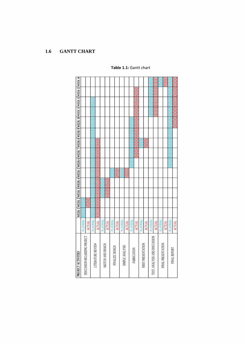
1.6 GANTT CHART
Table 1.1: Gantt chart
PROJ
ECT A
CTIV
ITIES
WEE
K 1
WEE
K 2
WEE
K 3
WEE
K 4
WEE
K 5
WEE
K 6
WEE
K 7
WEE
K 8
WEE
K 9
WEE
K 10
WEE
K 11
WEE
K 12
WEE
K 13
WEE
K 14
PLAN
NING
ACTU
ALPL
ANNI
NGAC
TUAL
PLAN
NING
ACTU
ALPL
ANNI
NGAC
TUAL
PLAN
NING
ACTU
ALPL
ANNI
NGAC
TUAL
PLAN
NING
ACTU
ALPL
ANNI
NGAC
TUAL
PLAN
NING
ACTU
ALPL
ANNI
NGAC
TUAL
FIRST
PRE
SENT
ATIO
N
TEST
, ANA
LYSI
S AN
D DI
SCUS
SION
FINAL
PRE
SENT
ATIO
N
FINAL
REP
ORT
DISC
USSI
ON R
EGAR
DING
PRO
JECT
LITER
ATUR
E RE
VIEW
SKET
CH A
ND D
ESIG
N
FINAL
IZE D
ESIG
N
SIMP
LE A
NALY
SIS
FABR
ICAT
ION
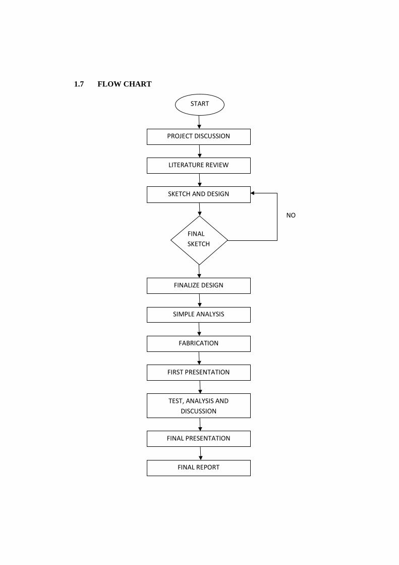
1.7 FLOW CHART
FINALIZE DESIGN
SIMPLE ANALYSIS
FABRICATION
FIRST PRESENTATION
TEST, ANALYSIS AND
DISCUSSION
FINAL PRESENTATION
FINAL REPORT
START
PROJECT DISCUSSION
LITERATURE REVIEW
SKETCH AND DESIGN
FINAL
SKETCH
NO
CHAPTER 2
LITERATURE REVIEW
2.1 LITERATURE REVIEW
2.1.1 Solar Turbine 1
Solar turbine or Solar Convection Turbine is a turbine which generates electricity
by natural convection of fluid by exposing the fluid to sun’s heat. When fluid is heated,
the density decreases, due to the increase of gaps between molecules. The area which is
exposed to heat will become less dense, thus the denser fluid will move downward,
causes the movement of fluid. This movement is called convection.
The ideas of producing solar turbine have been circulating among researchers for
years starting from the 20th century when a Spanish Colonel called Isidoro Cabanyes
proposed it in a scientific magazine but there are few efforts on producing one. One of
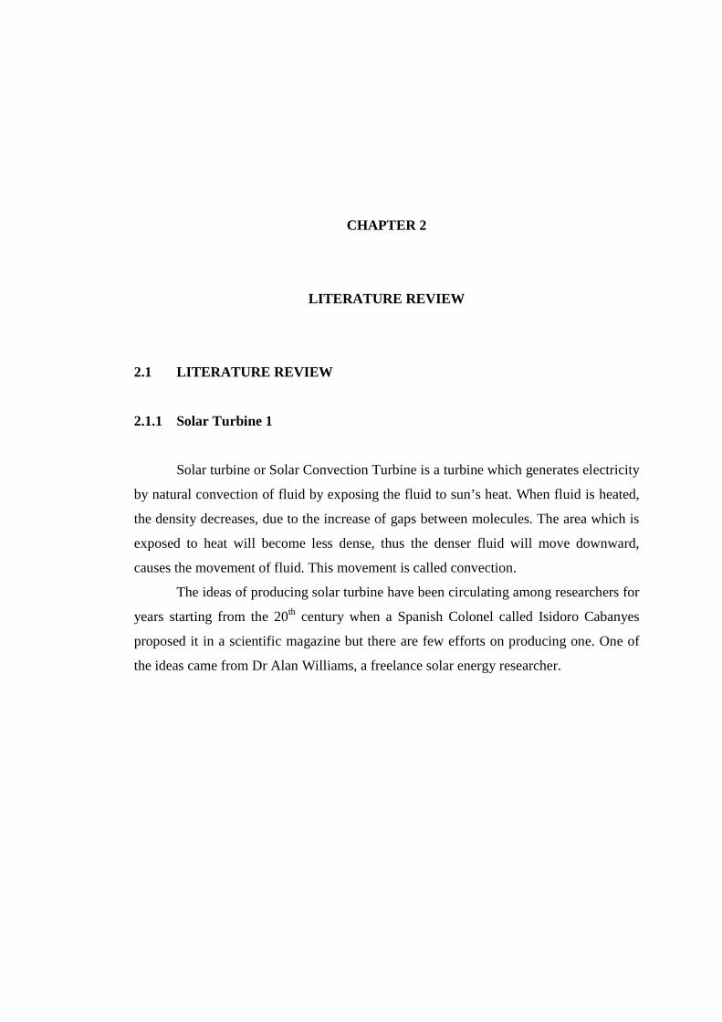
the ideas came from Dr Alan Williams, a freelance solar energy researcher.
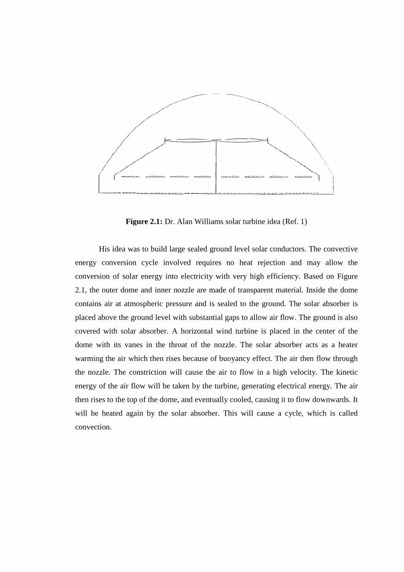
Figure 2.1
His idea was to build large sealed ground level solar conductors. The convective
energy conversion cycle involved requires no heat rejection and may allow the
conversion of solar energy into electricity with very high efficiency. Based on Figure
2.1, the outer dome and inner nozzle are made of transparent material. Inside the dome
contains air at atmospheric pressure and is sealed to the ground. The solar absorber is
placed above the ground level with substantial gaps to allow air flow. The ground is also
covered with solar absorber. A horizontal wind turbine is placed in the center of the
dome with its vanes in the throat of the nozzle. The solar absorber acts as a heater
warming the air which then rises because of buoyancy effect. The air then flow through
the nozzle. The constriction will cause the air to flow in a high velocity. The kinetic
energy of the air flow will be taken by the turbine, generating electrical energy. The air
then rises to the top of the dome, and eventually cooled, causing it to flow
will be heated again by the solar absorber. This will cause a cycle, which is called
convection.
Figure 2.1: Dr. Alan Williams solar turbine idea (Ref. 1)
His idea was to build large sealed ground level solar conductors. The convective
energy conversion cycle involved requires no heat rejection and may allow the
conversion of solar energy into electricity with very high efficiency. Based on Figure
uter dome and inner nozzle are made of transparent material. Inside the dome
contains air at atmospheric pressure and is sealed to the ground. The solar absorber is
placed above the ground level with substantial gaps to allow air flow. The ground is also
overed with solar absorber. A horizontal wind turbine is placed in the center of the
dome with its vanes in the throat of the nozzle. The solar absorber acts as a heater
warming the air which then rises because of buoyancy effect. The air then flow through
the nozzle. The constriction will cause the air to flow in a high velocity. The kinetic
energy of the air flow will be taken by the turbine, generating electrical energy. The air
then rises to the top of the dome, and eventually cooled, causing it to flow
will be heated again by the solar absorber. This will cause a cycle, which is called
Dr. Alan Williams solar turbine idea (Ref. 1)
His idea was to build large sealed ground level solar conductors. The convective
energy conversion cycle involved requires no heat rejection and may allow the
conversion of solar energy into electricity with very high efficiency. Based on Figure
uter dome and inner nozzle are made of transparent material. Inside the dome
contains air at atmospheric pressure and is sealed to the ground. The solar absorber is
placed above the ground level with substantial gaps to allow air flow. The ground is also
overed with solar absorber. A horizontal wind turbine is placed in the center of the
dome with its vanes in the throat of the nozzle. The solar absorber acts as a heater
warming the air which then rises because of buoyancy effect. The air then flow through
the nozzle. The constriction will cause the air to flow in a high velocity. The kinetic
energy of the air flow will be taken by the turbine, generating electrical energy. The air
then rises to the top of the dome, and eventually cooled, causing it to flow downwards. It
will be heated again by the solar absorber. This will cause a cycle, which is called
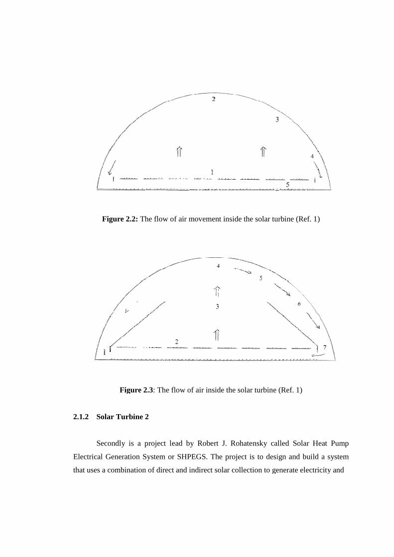
Figure 2.2:
Figure 2.3
2.1.2 Solar Turbine 2
Secondly is a project lead by Robert J. Rohatensky called Solar Heat Pump
Electrical Generation System or SHPEGS.
that uses a combination of direct and indirect solar collection to generate electricity and
The flow of air movement inside the solar turbine (Ref. 1)
Figure 2.3: The flow of air inside the solar turbine (Ref. 1)
olar Turbine 2
Secondly is a project lead by Robert J. Rohatensky called Solar Heat Pump
Electrical Generation System or SHPEGS. The project is to design and build a system
that uses a combination of direct and indirect solar collection to generate electricity and
The flow of air movement inside the solar turbine (Ref. 1)
: The flow of air inside the solar turbine (Ref. 1)
Secondly is a project lead by Robert J. Rohatensky called Solar Heat Pump
The project is to design and build a system
that uses a combination of direct and indirect solar collection to generate electricity and
store thermal energy in an economical, environmental friendly, scalable, reliable,
efficient and location independent manner using common construction materials. The
system is called “Energy Tower”.
Figure 2.4: SHPEGS illustration (Ref. 2)
The system is divided into two parts, the tower and the thermal solar collectors.
The thermal solar collectors absorb heat from the sun directly and warm up the
ammonia. In the tower, as hot air enters, it will heat the ammonia. The air then flows to
the wind turbine. The kinetic energy will turn into electricity. Excess heat then absorbs
by the heat sink and the air then flows out of the tower.
2.1.3 Solar Turbine 3
Third was a prototype, build in 1982 by German Ministry of Investigation and
Technology, in collaboration with Spanish Power Company Union Fenosa in the town of
Manzanares, Madrid.
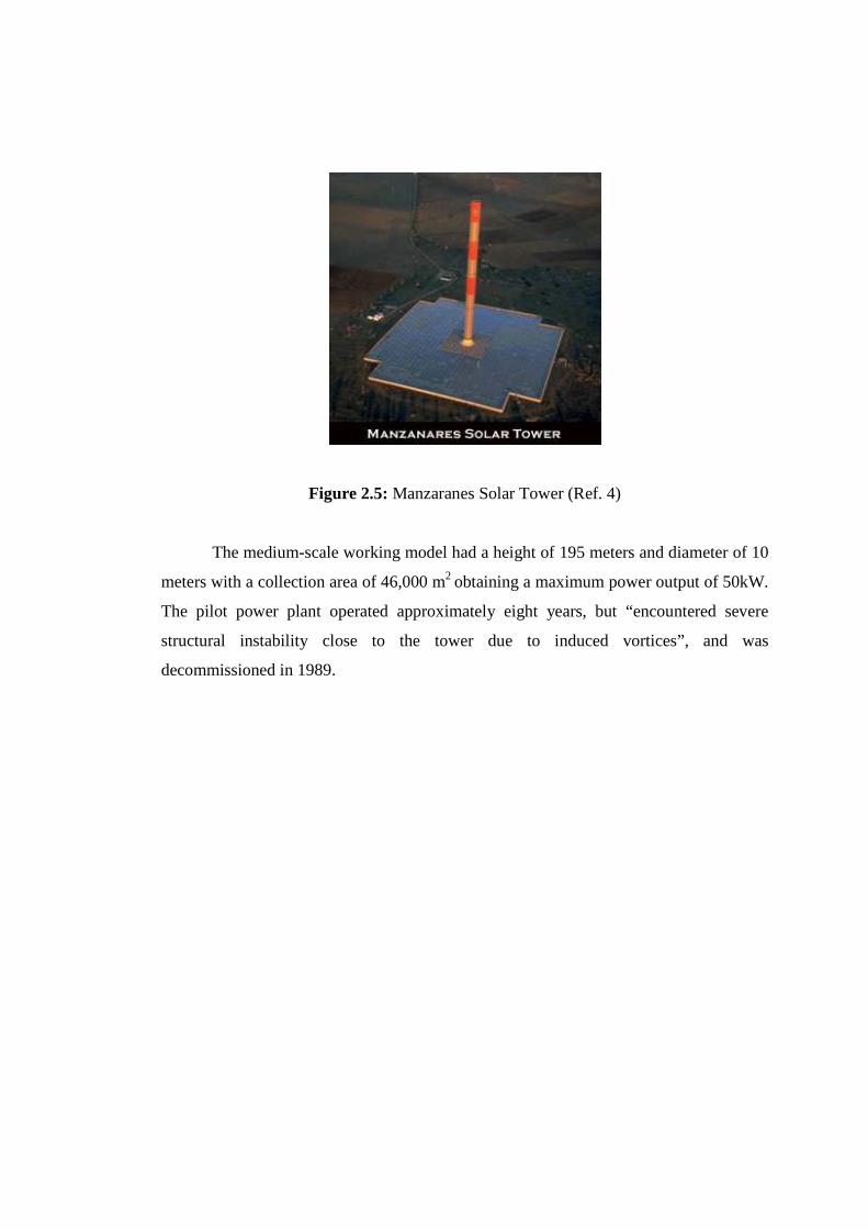
Figure 2.5: Manzaranes Solar Tower (Ref. 4)
The medium-scale working model had a height of 195 meters and diameter of 10
meters with a collection area of 46,000 m2 obtaining a maximum power output of 50kW.
The pilot power plant operated approximately eight years, but “encountered severe
structural instability close to the tower due to induced vortices”, and was
decommissioned in 1989.
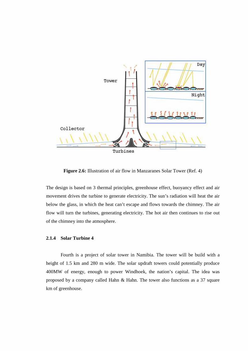
Figure 2.6: Illustration of air flow in Manzaranes Solar Tower (Ref. 4)
The design is based on 3 thermal principles, greenhouse effect, buoyancy effect and air
movement drives the turbine to generate electricity. The sun’s radiation will heat the air
below the glass, in which the heat can’t escape and flows towards the chimney. The air
flow will turn the turbines, generating electricity. The hot air then continues to rise out
of the chimney into the atmosphere.
2.1.4 Solar Turbine 4
Fourth is a project of solar tower in Namibia. The tower will be build with a
height of 1.5 km and 280 m wide. The solar updraft towers could potentially produce
400MW of energy, enough to power Windhoek, the nation’s capital. The idea was
proposed by a company called Hahn & Hahn. The tower also functions as a 37 square
km of greenhouse.
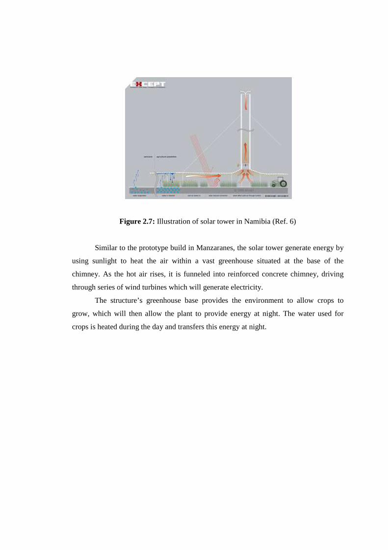
Figure 2.7: Illustration of solar tower in Namibia (Ref. 6)
Similar to the prototype build in Manzaranes, the solar tower generate energy by
using sunlight to heat the air within a vast greenhouse situated at the base of the
chimney. As the hot air rises, it is funneled into reinforced concrete chimney, driving
through series of wind turbines which will generate electricity.
The structure’s greenhouse base provides the environment to allow crops to
grow, which will then allow the plant to provide energy at night. The water used for
crops is heated during the day and transfers this energy at night.
CHAPTER 3
METHODOLOGY
3.1 DESIGN GENERATION
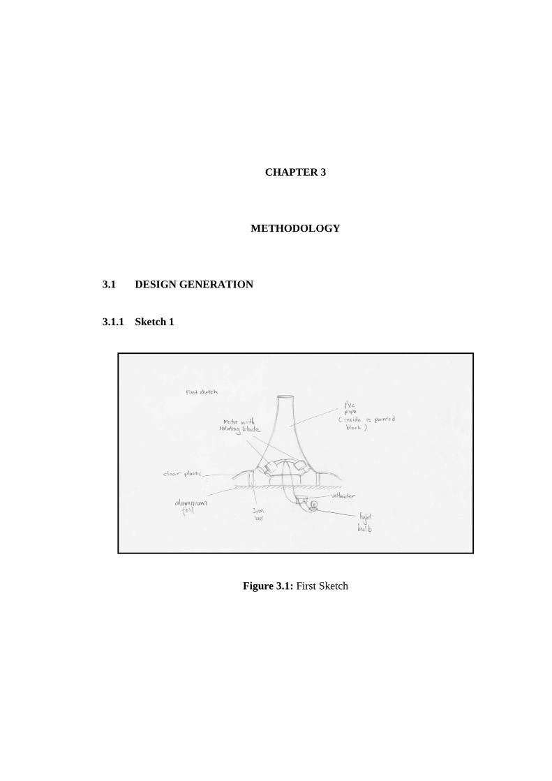
3.1.1 Sketch 1
Figure 3.1: First Sketch
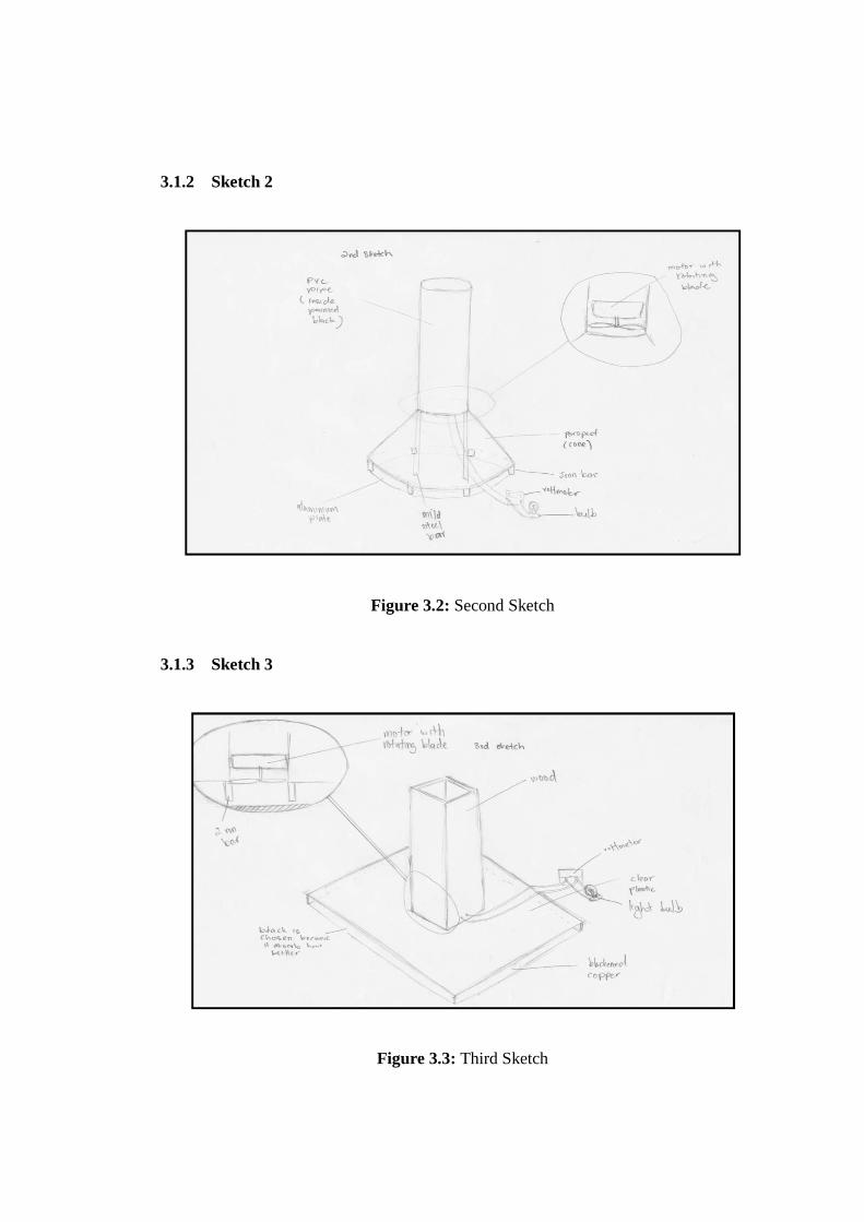
3.1.2 Sketch 2
Figure 3.2: Second Sketch
3.1.3 Sketch 3
Figure 3.3: Third Sketch
Recommended