Setting the standard for panel mounting www.fastmount.comPRODUCT CATALOGUE 2015
Designed for removable panels, the award winning Fastmount hidden mounting system delivers a flawless finish with perfect alignment everytime.
YEARS 20142004
SELF TAPPING FEMALE LP-F8
SELF TAPPING COARSE THREAD FEMALE CLIP LP-DF8
AUTO FIT FEMALE LP-AF8
SURFACE MOUNT MALE LP-SM8
SELF TAPPING MALE LP-M8
Copyright © 2012 Fastmount
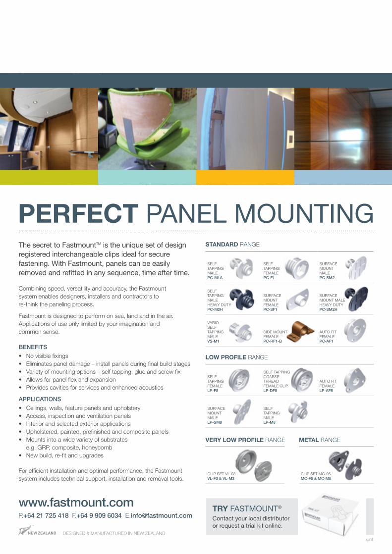
The secret to FastmountTM is the unique set of design registered interchangeable clips ideal for secure fastening. With Fastmount, panels can be easily removed and refitted in any sequence, time after time.
Combining speed, versatility and accuracy, the Fastmount system enables designers, installers and contractors to re-think the paneling process.
Fastmount is designed to perform on sea, land and in the air. Applications of use only limited by your imagination and common sense.
BENEFITS
• No visible fixings• Eliminates panel damage – install panels during final build stages• Variety of mounting options – self tapping, glue and screw fix• Allows for panel flex and expansion• Provides cavities for services and enhanced acoustics
APPLICATIONS
• Ceilings, walls, feature panels and upholstery• Access, inspection and ventilation panels• Interior and selected exterior applications• Upholstered, painted, prefinished and composite panels• Mounts into a wide variety of substrates
e.g. GRP, composite, honeycomb• New build, re-fit and upgrades
For efficient installation and optimal performance, the Fastmount system includes technical support, installation and removal tools.
PERFECT PANEL MOUNTINGSTANDARD RANGE
SELF TAPPING MALE PC-M1A
SELF TAPPING FEMALE PC-F1
SURFACE MOUNT MALE PC-SM2
SELF TAPPING MALE HEAVY DUTY PC-M2H
SURFACE MOUNT FEMALE PC-SF1
SURFACE MOUNT MALE HEAVY DUTY PC-SM2H
VARIO SELF TAPPING MALE VS-M1
SIDE MOUNT FEMALE PC-RF1-B
AUTO FIT FEMALE PC-AF1
LOW PROFILE RANGE
CLIP SET VL-03 VL-F3 & VL-M3
VERY LOW PROFILE RANGE
P.+64 21 725 418 F.+64 9 909 6034 [email protected] FASTMOUNT®
Contact your local distributor or request a trial kit online.
www.fastmount.com
DESIGNED & MANUFACTURED IN NEW ZEALAND
CLIP SET MC-05 MC-F5 & MC-M5
METAL RANGE
www.fastmount.com
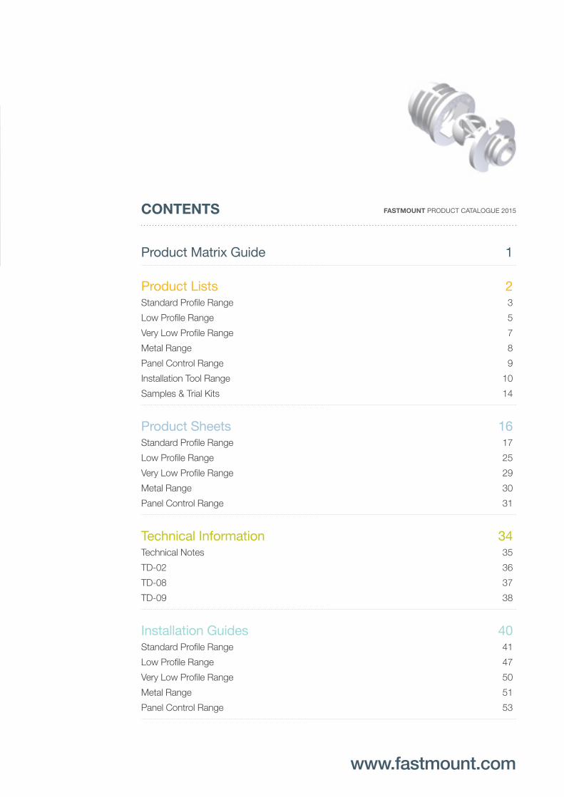
CONTENTS
Product Matrix Guide 1
Product Lists 2 Standard Profile Range 3
Low Profile Range 5
Very Low Profile Range 7
Metal Range 8
Panel Control Range 9
Installation Tool Range 10
Samples & Trial Kits 14
Product Sheets 16 Standard Profile Range 17
Low Profile Range 25
Very Low Profile Range 29
Metal Range 30
Panel Control Range 31
Technical Information 34 Technical Notes 35
TD-02 36
TD-08 37
TD-09 38
Installation Guides 40 Standard Profile Range 41
Low Profile Range 47
Very Low Profile Range 50
Metal Range 51
Panel Control Range 53
FASTMOUNT PRODUCT CATALOGUE 2015
1 | FASTMOUNT PRODUCT CATALOGUE 2015
FASTMOUNT Setting the standard for panel mounting
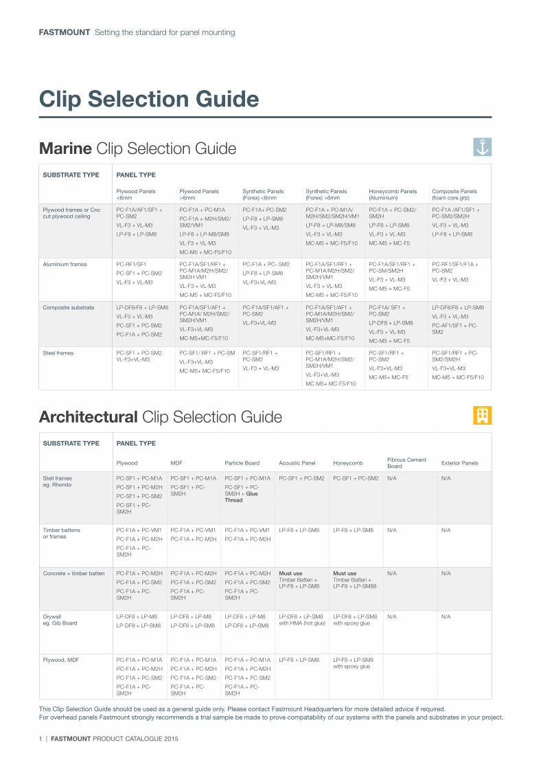
Clip Selection Guide
Marine Clip Selection Guide
Architectural Clip Selection Guide
SUBSTRATE TYPE PANEL TYPE
Plywood Panels <6mm
Plywood Panels >6mm
Synthetic Panels (Forex) <6mm
Synthetic Panels (Forex) >6mm
Honeycomb Panels (Aluminium)
Composite Panels (foam core grp)
Plywood frames or Cnc cut plywood ceiling
PC-F1A/AF1/SF1 + PC-SM2
VL-F3 + VL-M3
LP-F8 + LP-SM8
PC-F1A + PC-M1A
PC-F1A + M2H/SM2/SM2/VM1
LP-F8 + LP-M8/SM8
VL-F3 + VL-M3
MC-M5 + MC-F5/F10
PC-F1A+ PC-SM2
LP-F8 + LP-SM8
VL-F3 + VL-M3
PC-F1A + PC-M1A/M2H/SM2/SM2H/VM1
LP-F8 + LP-M8/SM8
VL-F3 + VL-M3
MC-M5 + MC-F5/F10
PC-F1A + PC-SM2/SM2H
LP-F8 + LP-SM8
VL-F3 + VL-M3
MC-M5 + MC-F5
PC-F1A /AF1/SF1 + PC-SM2/SM2H
VL-F3 + VL-M3
LP-F8 + LP-SM8
Aluminium frames PC-RF1/SF1
PC-SF1 + PC-SM2
VL-F3 + VL-M3
PC-F1A/SF1/RF1 + PC-M1A/M2H/SM2/SM2H VM1
VL-F3 + VL-M3
MC-M5 + MC-F5/F10
PC-F1A + PC- SM2
LP-F8 + LP-SM8
VL-F3+VL-M3
PC-F1A/SF1/RF1 + PC-M1A/M2H/SM2/SM2H/VM1
VL-F3 + VL-M3
MC-M5 + MC-F5/F10
PC-F1A/SF1/RF1 + PC-SM/SM2H
VL-F3 + VL-M3
MC-M5 + MC-F5
PC-RF1/SF1/F1A + PC-SM2
VL-F3 + VL-M3
Composite substrate LP-DF8/F8 + LP-SM8
VL-F3 + VL-M3
PC-SF1 + PC-SM2
PC-F1A + PC-SM2
PC-F1A/SF1/AF1 + PC-M1A/ M2H/SM2/SM2H/VM1
VL-F3+VL-M3
MC-M5+MC-F5/F10
PC-F1A/SF1/AF1 + PC-SM2
VL-F3+VL-M3
PC-F1A/SF1/AF1 + PC-M1A/M2H/SM2/SM2H/VM1
VL-F3+VL-M3
MC-M5+MC-F5/F10
PC-F1A/ SF1 + PC-SM2
LP-DF8 + LP-SM8
VL-F3 + VL-M3
MC-M5 + MC-F5
LP-DF8/F8 + LP-SM8
VL-F3 + VL-M3
PC-AF1/SF1 + PC-SM2
Steel frames PC-SF1 + PC-SM2 VL-F3+VL-M3
PC-SF1/ RF1 + PC-SM
VL-F3+VL-M3
MC-M5+ MC-F5/F10
PC-SF1/RF1 + PC-SM2
VL-F3 + VL-M3
PC-SF1/RF1 + PC-M1A/M2H/SM2/SM2H/VM1
VL-F3+VL-M3
MC-M5+ MC-F5/F10
PC-SF1/RF1 + PC-SM2
VL-F3+VL-M3
MC-M5+ MC-F5
PC-SF1/RF1 + PC-SM2/SM2H
VL-F3+VL-M3
MC-M5 + MC-F5/F10
SUBSTRATE TYPE PANEL TYPE
Plywood MDF Particle Board Acoustic Panel Honeycomb Fibrous Cement Board Exterior Panels
Stell frames eg. Rhondo
PC-SF1 + PC-M1A
PC-SF1 + PC-M2H
PC-SF1 + PC-SM2
PC-SF1 + PC-SM2H
PC-SF1 + PC-M1A
PC-SF1 + PC-SM2H
PC-SF1 + PC-M1A
PC-SF1 + PC-SM2H + Glue Thread
PC-SF1 + PC-SM2 PC-SF1 + PC-SM2 N/A N/A
Timber battens or frames
PC-F1A + PC-VM1
PC-F1A + PC-M2H
PC-F1A + PC-SM2H
PC-F1A + PC-VM1
PC-F1A + PC-M2H
PC-F1A + PC-VM1
PC-F1A + PC-M2H
LP-F8 + LP-SM8 LP-F8 + LP-SM8 N/A N/A
Concrete + timber batten PC-F1A + PC-M2H
PC-F1A + PC-SM2
PC-F1A + PC-SM2H
PC-F1A + PC-M2H
PC-F1A + PC-SM2
PC-F1A + PC-SM2H
PC-F1A + PC-M2H
PC-F1A + PC-SM2
PC-F1A + PC-SM2H
Must use Timber Batten + LP-F8 + LP-SM8
Must use Timber Batten + LP-F8 + LP-SM88
N/A N/A
Drywall eg. Gib Board
LP-DF8 + LP-M8
LP-DF8 + LP-SM8
LP-DF8 + LP-M8
LP-DF8 + LP-SM8
LP-DF8 + LP-M8
LP-DF8 + LP-SM8
LP-DF8 + LP-SM8 with HMA (hot glue)
LP-DF8 + LP-SM8 with epoxy glue
N/A N/A
Plywood, MDF PC-F1A + PC-M1A
PC-F1A + PC-M2H
PC-F1A + PC-SM2
PC-F1A + PC-SM2H
PC-F1A + PC-M1A
PC-F1A + PC-M2H
PC-F1A + PC-SM2
PC-F1A + PC-SM2H
PC-F1A + PC-M1A
PC-F1A + PC-M2H
PC-F1A + PC-SM2
PC-F1A + PC-SM2H
LP-F8 + LP-SM8 LP-F8 + LP-SM8 with epoxy glue
This Clip Selection Guide should be used as a general guide only. Please contact Fastmount Headquarters for more detailed advice if required.For overhead panels Fastmount strongly recommends a trial sample be made to prove compatability of our systems with the panels and substrates in your project.
FASTMOUNT PRODUCT CATALOGUE 2015 | 2
www.fastmount.com
Product Lists
Standard Profile Range
Low Profile Range
Very Low Profile Range
Metal Range
Panel Control
Installation Tools
3 | FASTMOUNT PRODUCT CATALOGUE 2015
FASTMOUNT Setting the standard for panel mounting
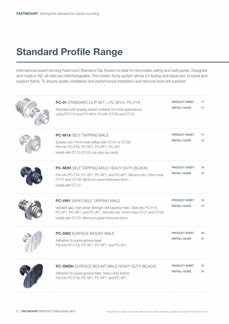
PC-01 STANDARD CLIP SET = PC-M1A+ PC-F1A
Standard self tapping system suitable for most applications, using PC-F1A and PC-M1A. Fit with CT-03 and CT-10.
PRODUCT SHEET 17
INSTALL GUIDE 41
PC-M1A SELF TAPPING MALE
Screws into 10mm hole drilled with CT-01 or CT-09. Fits into PC-F1A, PC-SF1, PC-RF1, PC-AF1.
Install with CT-10 (CT-04 can also be used).
PRODUCT SHEET 17
INSTALL GUIDE 41
PC-M2H SELF TAPPING MALE HEAVY DUTY (BLACK)
Fits into PC-F1A, PC-SF1, PC-RF1, and PC-AF1. Mounts into 10mm hole CT-01 and CT-09. Minimum panel thickness 9mm.
Install with CT-10.
PRODUCT SHEET 18
INSTALL GUIDE 41
PC-VM1 VARIO SELF TAPPING MALE
Variable gap, high shear strength self tapping male. Clips into PC-F1A, PC-SF1, PC-RF1, and PC-AF1. Mounts into 10mm hole CT-01 and CT-09.
Install with CT-10. Minimum panel thickness 9mm.
PRODUCT SHEET 19
INSTALL GUIDE 41
PC-SM2 SURFACE MOUNT MALE
Adhesive fix super-groove base. Fits into PC-F1A, PC-SF1, PC-RF1, and PC-AF1.
PRODUCT SHEET 20
INSTALL GUIDE 41
PC-SM2H SURFACE MOUNT MALE HEAVY DUTY (BLACK)
Adhesive fix super-groove base, heavy duty (black). Fits into PC-F1A, PC-SF1, PC-RF1, and PC-AF1.
PRODUCT SHEET 21
INSTALL GUIDE 41
International award winning Fastmount Standard Clip System is ideal for removable ceiling and wall panels. Designed and made in NZ, all clips are interchangeable. This hidden fixing system allows for flexing and expansion of panel and support frame. To ensure quality installation and performance installation and removal tools are supplied.
Standard Profile Range
*Specification subject to change without notice. See website for updates. Copyright © Fastmount Ltd.
FASTMOUNT PRODUCT CATALOGUE 2015 | 4
www.fastmount.com
Product Lists
CP-01A PAGE 10
CP-01ST PAGE 10
CT-01 PAGE 11
CT-09 PAGE 11
CT-07 PAGE 11
CT-13A PAGE 11
CT-15 PAGE 11
CT-03 PAGE 11
CT-10 PAGE 11
CT-05 PAGE 12
CT-17 PAGE 12
CT-18 PAGE 12
CT-08 PAGE 12
CT-06S PAGE 13
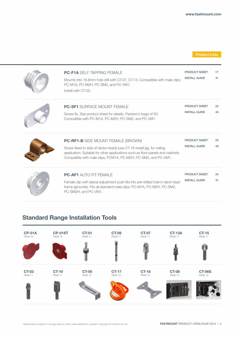
PC-F1A SELF TAPPING FEMALE
Mounts into 16.8mm hole drill with CT-07, CT-13. Compatible with male clips, PC-M1A, PC-M2H, PC-SM2, and PC-VM1.
Install with CT-03.
PRODUCT SHEET 17
INSTALL GUIDE 41
PC-SF1 SURFACE MOUNT FEMALE
Screw fix. See product sheet for details. Packed in bags of 50. Compatible with PC-M1A, PC-M2H, PC-SM2, and PC-VM1.
PRODUCT SHEET 22
INSTALL GUIDE 43
PC-RF1-B SIDE MOUNT FEMALE (BROWN)
Screw fixed to side of decks heads (use CT-18 install jig), for ceiling application. Suitable for other applications such as floor panels and cabinets. Compatible with male clips, PCM1A, PC-M2H, PC-SM2, and PC-VM1.
PRODUCT SHEET 23
INSTALL GUIDE 45
PC-AF1 AUTO FIT FEMALE
Female clip with lateral adjustment push fits into pre-drilled hole in deck head frame (grounds). Fits all standard male clips: PC-M1A, PC-M2H, PC-SM2, PC-SM2H, and PC-VM1.
PRODUCT SHEET 24
INSTALL GUIDE 41
Standard Range Installation Tools
*Specification subject to change without notice. See website for updates. Copyright © Fastmount Ltd.
5 | FASTMOUNT PRODUCT CATALOGUE 2015
FASTMOUNT Setting the standard for panel mounting
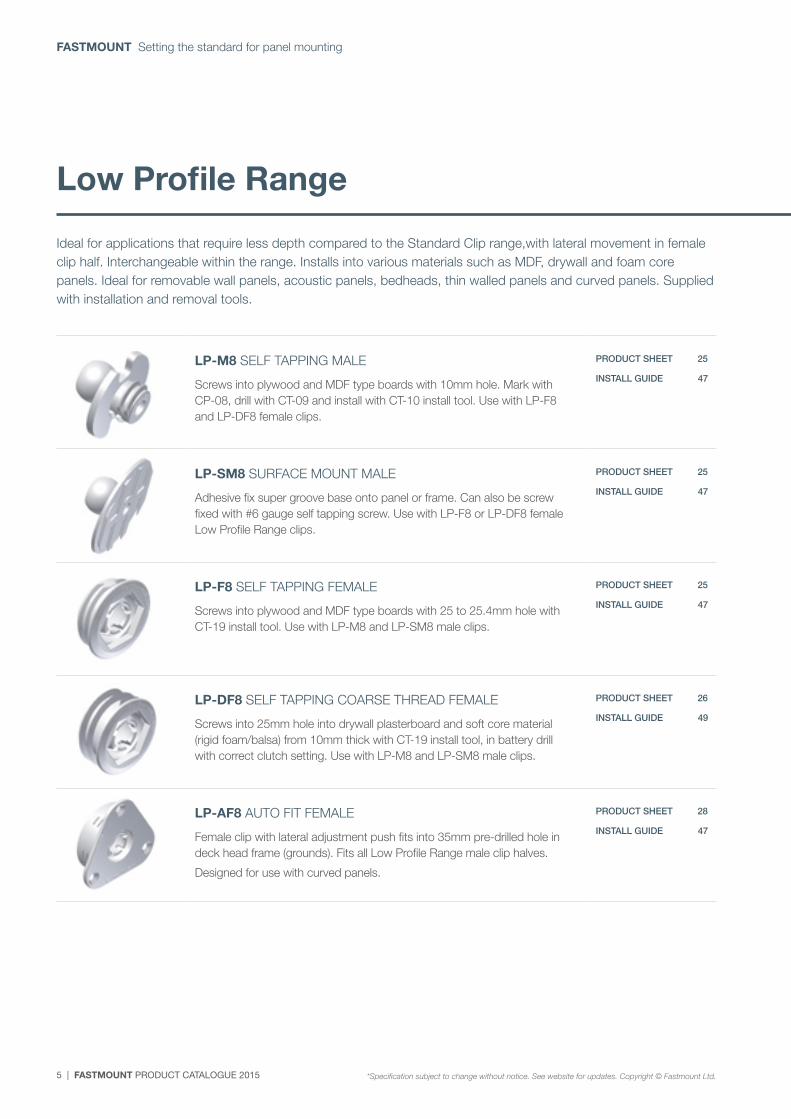
Ideal for applications that require less depth compared to the Standard Clip range,with lateral movement in female clip half. Interchangeable within the range. Installs into various materials such as MDF, drywall and foam core panels. Ideal for removable wall panels, acoustic panels, bedheads, thin walled panels and curved panels. Supplied with installation and removal tools.
Low Profile Range
LP-M8 SELF TAPPING MALE
Screws into plywood and MDF type boards with 10mm hole. Mark with CP-08, drill with CT-09 and install with CT-10 install tool. Use with LP-F8 and LP-DF8 female clips.
PRODUCT SHEET 25
INSTALL GUIDE 47
LP-SM8 SURFACE MOUNT MALE
Adhesive fix super groove base onto panel or frame. Can also be screw fixed with #6 gauge self tapping screw. Use with LP-F8 or LP-DF8 female Low Profile Range clips.
PRODUCT SHEET 25
INSTALL GUIDE 47
LP-F8 SELF TAPPING FEMALE
Screws into plywood and MDF type boards with 25 to 25.4mm hole with CT-19 install tool. Use with LP-M8 and LP-SM8 male clips.
PRODUCT SHEET 25
INSTALL GUIDE 47
LP-DF8 SELF TAPPING COARSE THREAD FEMALE
Screws into 25mm hole into drywall plasterboard and soft core material (rigid foam/balsa) from 10mm thick with CT-19 install tool, in battery drill with correct clutch setting. Use with LP-M8 and LP-SM8 male clips.
PRODUCT SHEET 26
INSTALL GUIDE 49
LP-AF8 AUTO FIT FEMALE
Female clip with lateral adjustment push fits into 35mm pre-drilled hole in deck head frame (grounds). Fits all Low Profile Range male clip halves.
Designed for use with curved panels.
PRODUCT SHEET 28
INSTALL GUIDE 47
*Specification subject to change without notice. See website for updates. Copyright © Fastmount Ltd.
FASTMOUNT PRODUCT CATALOGUE 2015 | 6
www.fastmount.com
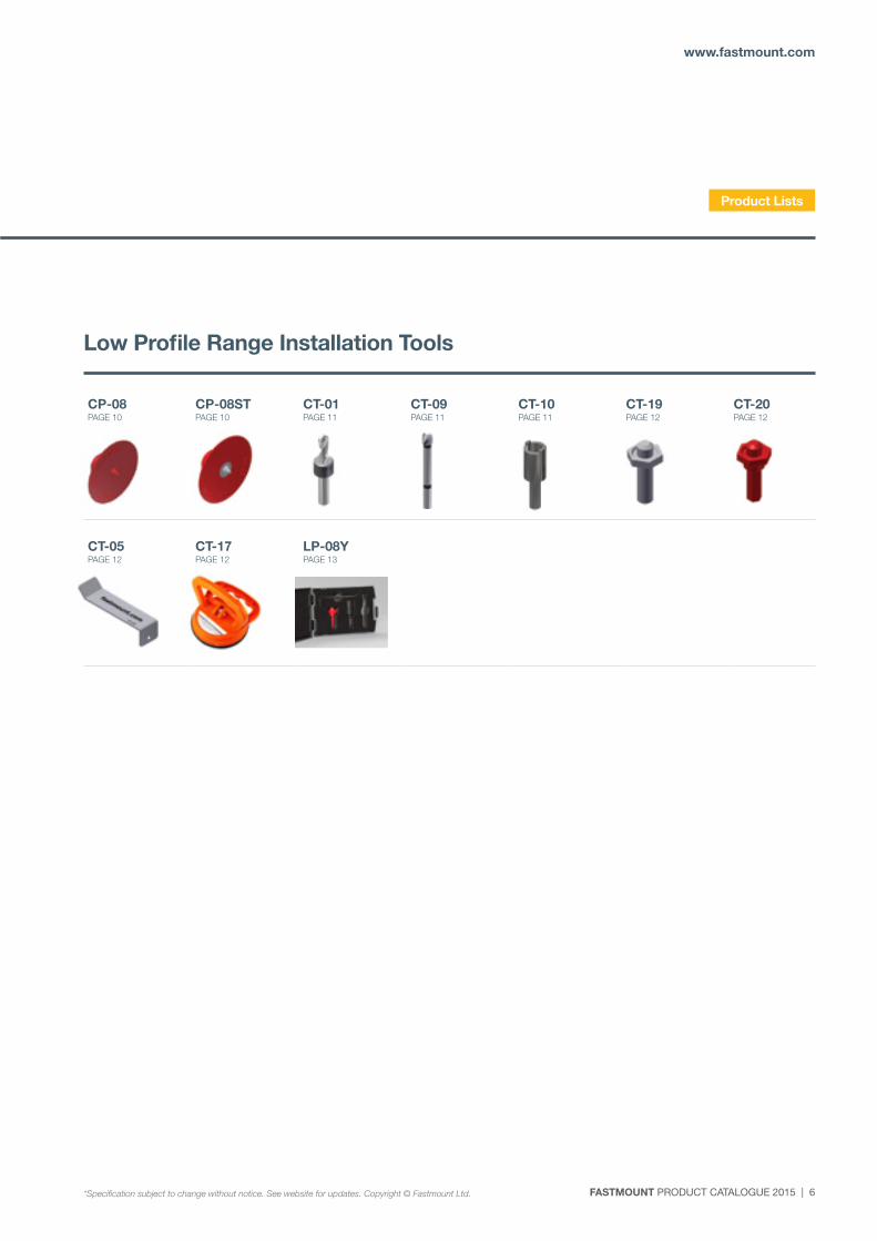
CP-08 PAGE 10
CP-08ST PAGE 10
CT-01 PAGE 11
CT-09 PAGE 11
CT-10 PAGE 11
CT-19 PAGE 12
CT-20 PAGE 12
CT-05 PAGE 12
CT-17 PAGE 12
LP-08Y PAGE 13
Low Profile Range Installation Tools
Product Lists
*Specification subject to change without notice. See website for updates. Copyright © Fastmount Ltd.
7 | FASTMOUNT PRODUCT CATALOGUE 2015
FASTMOUNT Setting the standard for panel mounting
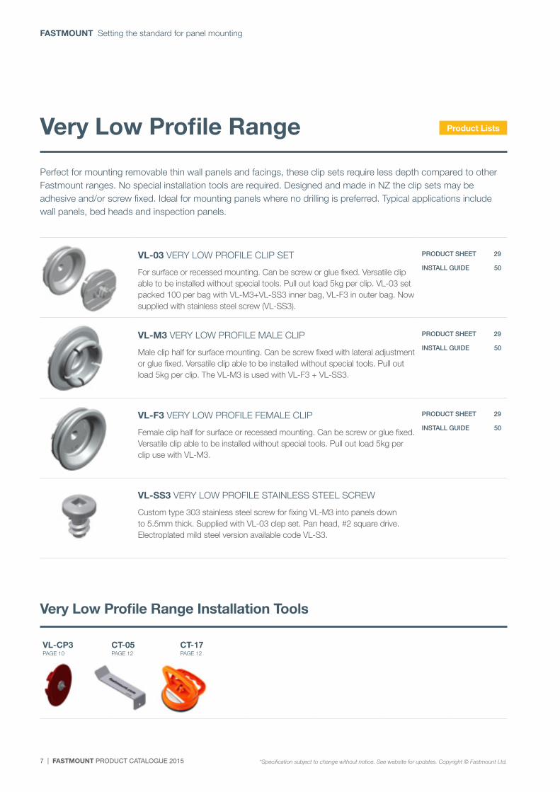
VL-03 VERY LOW PROFILE CLIP SET
For surface or recessed mounting. Can be screw or glue fixed. Versatile clip able to be installed without special tools. Pull out load 5kg per clip. VL-03 set packed 100 per bag with VL-M3+VL-SS3 inner bag, VL-F3 in outer bag. Now supplied with stainless steel screw (VL-SS3).
PRODUCT SHEET 29
INSTALL GUIDE 50
VL-M3 VERY LOW PROFILE MALE CLIP
Male clip half for surface mounting. Can be screw fixed with lateral adjustment or glue fixed. Versatile clip able to be installed without special tools. Pull out load 5kg per clip. The VL-M3 is used with VL-F3 + VL-SS3.
PRODUCT SHEET 29
INSTALL GUIDE 50
VL-F3 VERY LOW PROFILE FEMALE CLIP
Female clip half for surface or recessed mounting. Can be screw or glue fixed. Versatile clip able to be installed without special tools. Pull out load 5kg per clip use with VL-M3.
PRODUCT SHEET 29
INSTALL GUIDE 50
VL-SS3 VERY LOW PROFILE STAINLESS STEEL SCREW
Custom type 303 stainless steel screw for fixing VL-M3 into panels down to 5.5mm thick. Supplied with VL-03 clep set. Pan head, #2 square drive. Electroplated mild steel version available code VL-S3.
Perfect for mounting removable thin wall panels and facings, these clip sets require less depth compared to other Fastmount ranges. No special installation tools are required. Designed and made in NZ the clip sets may be adhesive and/or screw fixed. Ideal for mounting panels where no drilling is preferred. Typical applications include wall panels, bed heads and inspection panels.
Very Low Profile Range Installation Tools
VL-CP3 PAGE 10
CT-05 PAGE 12
CT-17 PAGE 12
Very Low Profile Range Product Lists
*Specification subject to change without notice. See website for updates. Copyright © Fastmount Ltd.
FASTMOUNT PRODUCT CATALOGUE 2015 | 8
www.fastmount.com
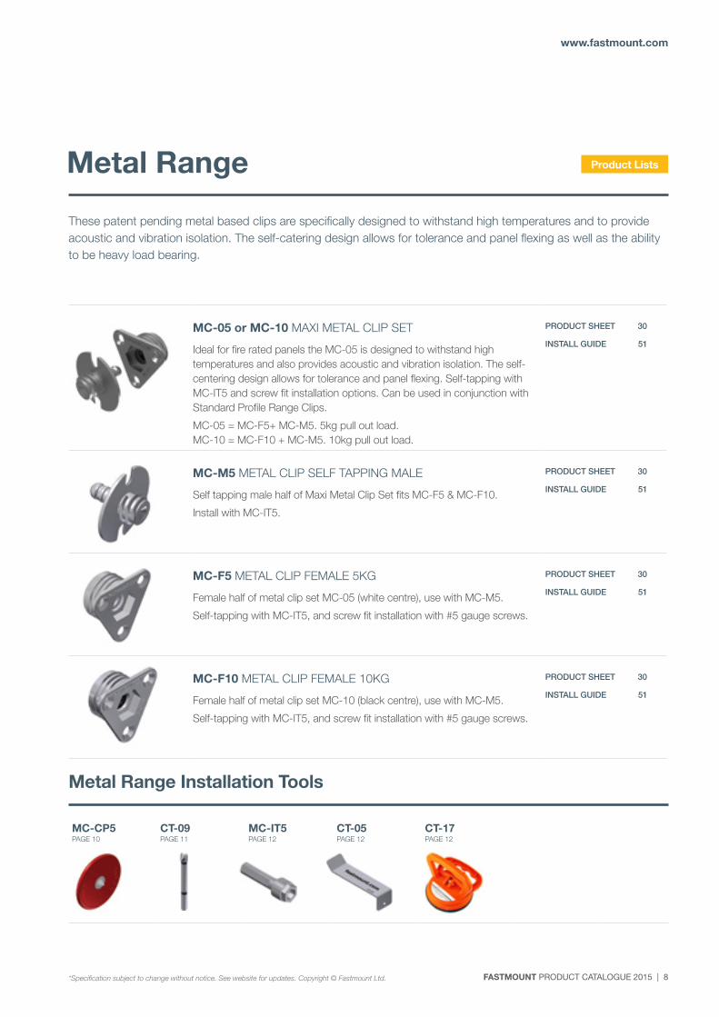
MC-05 or MC-10 MAXI METAL CLIP SET
Ideal for fire rated panels the MC-05 is designed to withstand high temperatures and also provides acoustic and vibration isolation. The self-centering design allows for tolerance and panel flexing. Self-tapping with MC-IT5 and screw fit installation options. Can be used in conjunction with Standard Profile Range Clips.
MC-05 = MC-F5+ MC-M5. 5kg pull out load. MC-10 = MC-F10 + MC-M5. 10kg pull out load.
PRODUCT SHEET 30
INSTALL GUIDE 51
MC-M5 METAL CLIP SELF TAPPING MALE
Self tapping male half of Maxi Metal Clip Set fits MC-F5 & MC-F10.
Install with MC-IT5.
PRODUCT SHEET 30
INSTALL GUIDE 51
MC-F5 METAL CLIP FEMALE 5KG
Female half of metal clip set MC-05 (white centre), use with MC-M5.
Self-tapping with MC-IT5, and screw fit installation with #5 gauge screws.
PRODUCT SHEET 30
INSTALL GUIDE 51
MC-F10 METAL CLIP FEMALE 10KG
Female half of metal clip set MC-10 (black centre), use with MC-M5.
Self-tapping with MC-IT5, and screw fit installation with #5 gauge screws.
PRODUCT SHEET 30
INSTALL GUIDE 51
These patent pending metal based clips are specifically designed to withstand high temperatures and to provide acoustic and vibration isolation. The self-catering design allows for tolerance and panel flexing as well as the ability to be heavy load bearing.
Metal Range Installation Tools
MC-CP5 PAGE 10
CT-09 PAGE 11
MC-IT5 PAGE 12
CT-05 PAGE 12
CT-17 PAGE 12
Metal Range Product Lists
*Specification subject to change without notice. See website for updates. Copyright © Fastmount Ltd.
9 | FASTMOUNT PRODUCT CATALOGUE 2015
FASTMOUNT Setting the standard for panel mounting
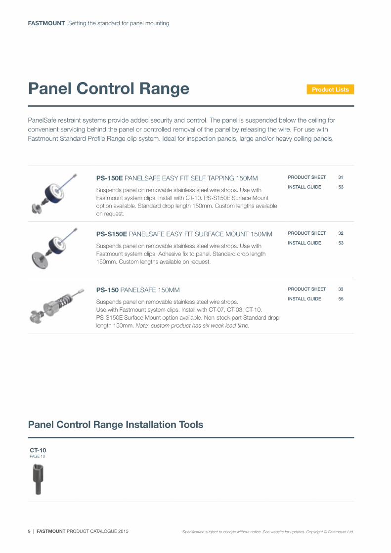
PanelSafe restraint systems provide added security and control. The panel is suspended below the ceiling for convenient servicing behind the panel or controlled removal of the panel by releasing the wire. For use with Fastmount Standard Profile Range clip system. Ideal for inspection panels, large and/or heavy ceiling panels.
Panel Control Range Installation Tools
CT-10 PAGE 10
Panel Control Range
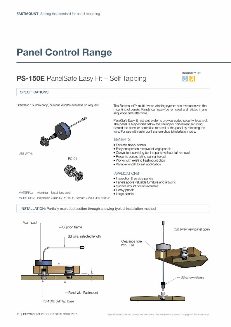
PS-150E PANELSAFE EASY FIT SELF TAPPING 150MM
Suspends panel on removable stainless steel wire strops. Use with Fastmount system clips. Install with CT-10. PS-S150E Surface Mount option available. Standard drop length 150mm. Custom lengths available on request.
PRODUCT SHEET 31
INSTALL GUIDE 53
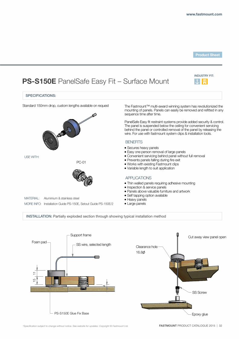
PS-S150E PANELSAFE EASY FIT SURFACE MOUNT 150MM
Suspends panel on removable stainless steel wire strops. Use with Fastmount system clips. Adhesive fix to panel. Standard drop length 150mm. Custom lengths available on request.
PRODUCT SHEET 32
INSTALL GUIDE 53
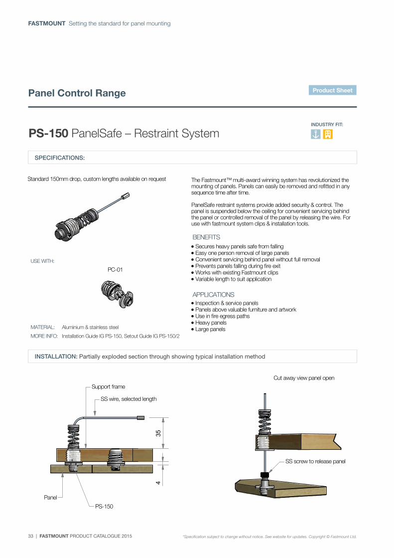
PS-150 PANELSAFE 150MM
Suspends panel on removable stainless steel wire strops. Use with Fastmount system clips. Install with CT-07, CT-03, CT-10. PS-S150E Surface Mount option available. Non-stock part Standard drop length 150mm. Note: custom product has six week lead time.
PRODUCT SHEET 33
INSTALL GUIDE 55
Product Lists
*Specification subject to change without notice. See website for updates. Copyright © Fastmount Ltd.
FASTMOUNT PRODUCT CATALOGUE 2015 | 10
www.fastmount.com
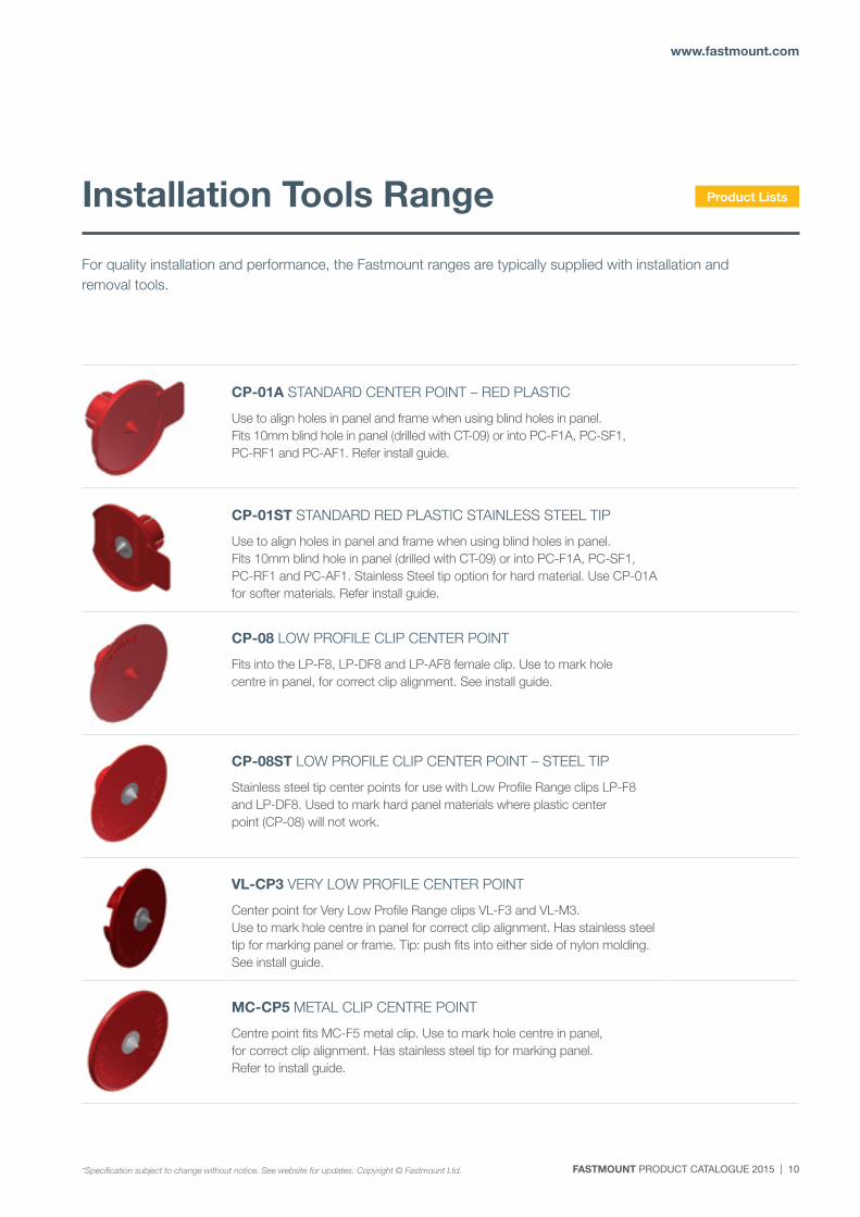
CP-01A STANDARD CENTER POINT – RED PLASTIC
Use to align holes in panel and frame when using blind holes in panel. Fits 10mm blind hole in panel (drilled with CT-09) or into PC-F1A, PC-SF1, PC-RF1 and PC-AF1. Refer install guide.
CP-01ST STANDARD RED PLASTIC STAINLESS STEEL TIP
Use to align holes in panel and frame when using blind holes in panel. Fits 10mm blind hole in panel (drilled with CT-09) or into PC-F1A, PC-SF1, PC-RF1 and PC-AF1. Stainless Steel tip option for hard material. Use CP-01A for softer materials. Refer install guide.
CP-08 LOW PROFILE CLIP CENTER POINT
Fits into the LP-F8, LP-DF8 and LP-AF8 female clip. Use to mark hole centre in panel, for correct clip alignment. See install guide.
CP-08ST LOW PROFILE CLIP CENTER POINT – STEEL TIP
Stainless steel tip center points for use with Low Profile Range clips LP-F8 and LP-DF8. Used to mark hard panel materials where plastic center point (CP-08) will not work.
VL-CP3 VERY LOW PROFILE CENTER POINT
Center point for Very Low Profile Range clips VL-F3 and VL-M3. Use to mark hole centre in panel for correct clip alignment. Has stainless steel tip for marking panel or frame. Tip: push fits into either side of nylon molding. See install guide.
MC-CP5 METAL CLIP CENTRE POINT
Centre point fits MC-F5 metal clip. Use to mark hole centre in panel, for correct clip alignment. Has stainless steel tip for marking panel. Refer to install guide.
For quality installation and performance, the Fastmount ranges are typically supplied with installation and removal tools.
Installation Tools Range Product Lists
*Specification subject to change without notice. See website for updates. Copyright © Fastmount Ltd.
11 | FASTMOUNT PRODUCT CATALOGUE 2015
FASTMOUNT Setting the standard for panel mounting
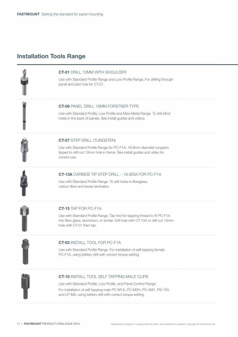
CT-01 DRILL 10MM WITH SHOULDER
Use with Standard Profile Range and Low Profile Range. For drilling through panel and pilot hole for CT-07.
CT-09 PANEL DRILL 10MM FORSTNER TYPE
Use with Standard Profile, Low Profile and Maxi Metal Range. To drill blind holes in the back of panels. See install guides and videos
CT-07 STEP DRILL (TUNGSTEN)
Use with Standard Profile Range for PC-F1A, 16.8mm diameter tungsten tipped to drill out 10mm hole in frame. See install guides and video for correct use.
CT-13A CARBIDE TIP STEP DRILL – 16.8DIA FOR PC-F1A
Use with Standard Profile Range. To drill holes in fibreglass, carbon fibre and kevlar laminates.
CT-15 TAP FOR PC-F1A
Use with Standard Profile Range. Tap tool for tapping thread to fit PC-F1A into fibre glass, aluminium, or similar. Drill hole with CT-13A or drill out 10mm hole with CT-07 then tap.
CT-03 INSTALL TOOL FOR PC-F1A
Use with Standard Profile Range. For installation of self tapping female PC-F1A, using battery drill with correct torque setting.
CT-10 INSTALL TOOL SELF TAPPING MALE CLIPS
Use with Standard Profile, Low Profile, and Panel Control Range.
For installation of self tapping male PC-M1A, PC-M2H, PC-VM1, PS-150, and LP-M8, using battery drill with correct torque setting.
Installation Tools Range
*Specification subject to change without notice. See website for updates. Copyright © Fastmount Ltd.
FASTMOUNT PRODUCT CATALOGUE 2015 | 12
www.fastmount.com
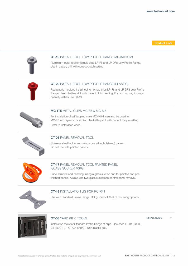
CT-19 INSTALL TOOL LOW PROFILE RANGE (ALUMINIUM)
Aluminium install tool for female clips LP-F8 and LP-DF8 Low Profile Range. Use in battery drill with correct clutch setting.
CT-20 INSTALL TOOL LOW PROFILE RANGE (PLASTIC)
Red plastic moulded install tool for female clips LP-F8 and LP-DF8 Low Profile Range. Use in battery drill with correct clutch setting. For normal use, for large quantity installs use CT-19.
MC-IT5 METAL CLIPS MC-F5 & MC-M5
For installation of self tapping male MC-M5H, can also be used for MC-F5 into plywood or similar. Use battery drill with correct torque setting.
Refer to installation video.
CT-05 PANEL REMOVAL TOOL
Stainless steel tool for removing covered (upholstered) panels. Do not use with painted panels.
CT-17 PANEL REMOVAL TOOL PAINTED PANEL (GLASS SUCKER 40KG)
Panel removal and handling, using a glass suction cup for painted and pre-finished panels. Always use two glass suckers to control panel removal.
CT-18 INSTALLATION JIG FOR PC-RF1
Use with Standard Profile Range. Drill guide for PC-RF1 mounting options.
CT-08 YARD KIT 6 TOOLS
Installation tools for Standard Profile Range of clips. One each CT-01, CT-03, CT-05, CT-07, CT-09, and CT-10 in plastic box.
INSTALL GUIDE 41
Product Lists
*Specification subject to change without notice. See website for updates. Copyright © Fastmount Ltd.
13 | FASTMOUNT PRODUCT CATALOGUE 2015
FASTMOUNT Setting the standard for panel mounting
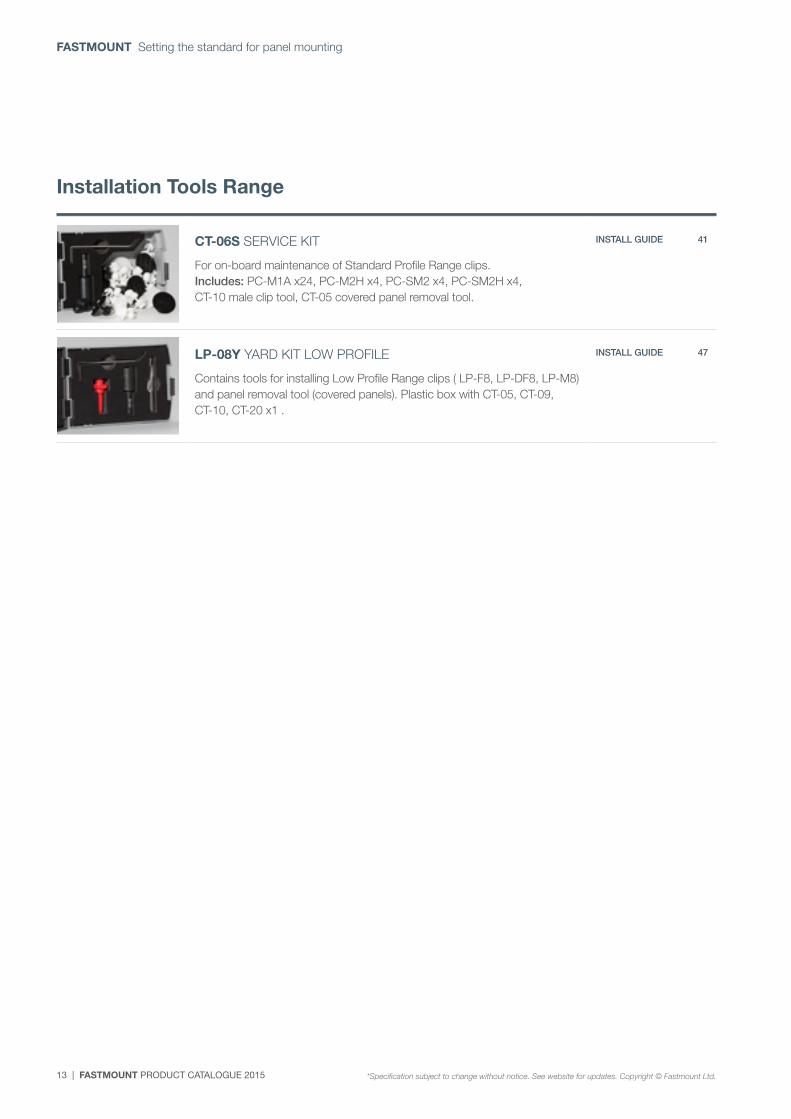
CT-06S SERVICE KIT
For on-board maintenance of Standard Profile Range clips. Includes: PC-M1A x24, PC-M2H x4, PC-SM2 x4, PC-SM2H x4, CT-10 male clip tool, CT-05 covered panel removal tool.
INSTALL GUIDE 41
LP-08Y YARD KIT LOW PROFILE
Contains tools for installing Low Profile Range clips ( LP-F8, LP-DF8, LP-M8) and panel removal tool (covered panels). Plastic box with CT-05, CT-09, CT-10, CT-20 x1 .
INSTALL GUIDE 47
Installation Tools Range
*Specification subject to change without notice. See website for updates. Copyright © Fastmount Ltd.
FASTMOUNT PRODUCT CATALOGUE 2015 | 14
www.fastmount.com
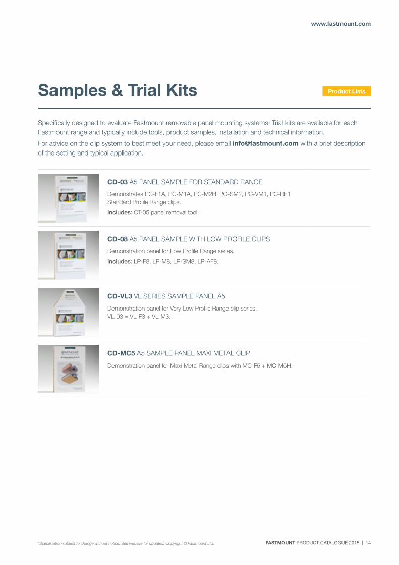
CD-03 A5 PANEL SAMPLE FOR STANDARD RANGE
Demonstrates PC-F1A, PC-M1A, PC-M2H, PC-SM2, PC-VM1, PC-RF1 Standard Profile Range clips.
Includes: CT-05 panel removal tool.
CD-08 A5 PANEL SAMPLE WITH LOW PROFILE CLIPS
Demonstration panel for Low Profile Range series.
Includes: LP-F8, LP-M8, LP-SM8, LP-AF8.
CD-VL3 VL SERIES SAMPLE PANEL A5
Demonstration panel for Very Low Profile Range clip series. VL-03 = VL-F3 + VL-M3.
CD-MC5 A5 SAMPLE PANEL MAXI METAL CLIP
Demonstration panel for Maxi Metal Range clips with MC-F5 + MC-M5H.
Specifically designed to evaluate Fastmount removable panel mounting systems. Trial kits are available for each Fastmount range and typically include tools, product samples, installation and technical information.
For advice on the clip system to best meet your need, please email [email protected] with a brief description of the setting and typical application.
Samples & Trial Kits Product Lists
*Specification subject to change without notice. See website for updates. Copyright © Fastmount Ltd.
15 | FASTMOUNT PRODUCT CATALOGUE 2015
FASTMOUNT Setting the standard for panel mounting
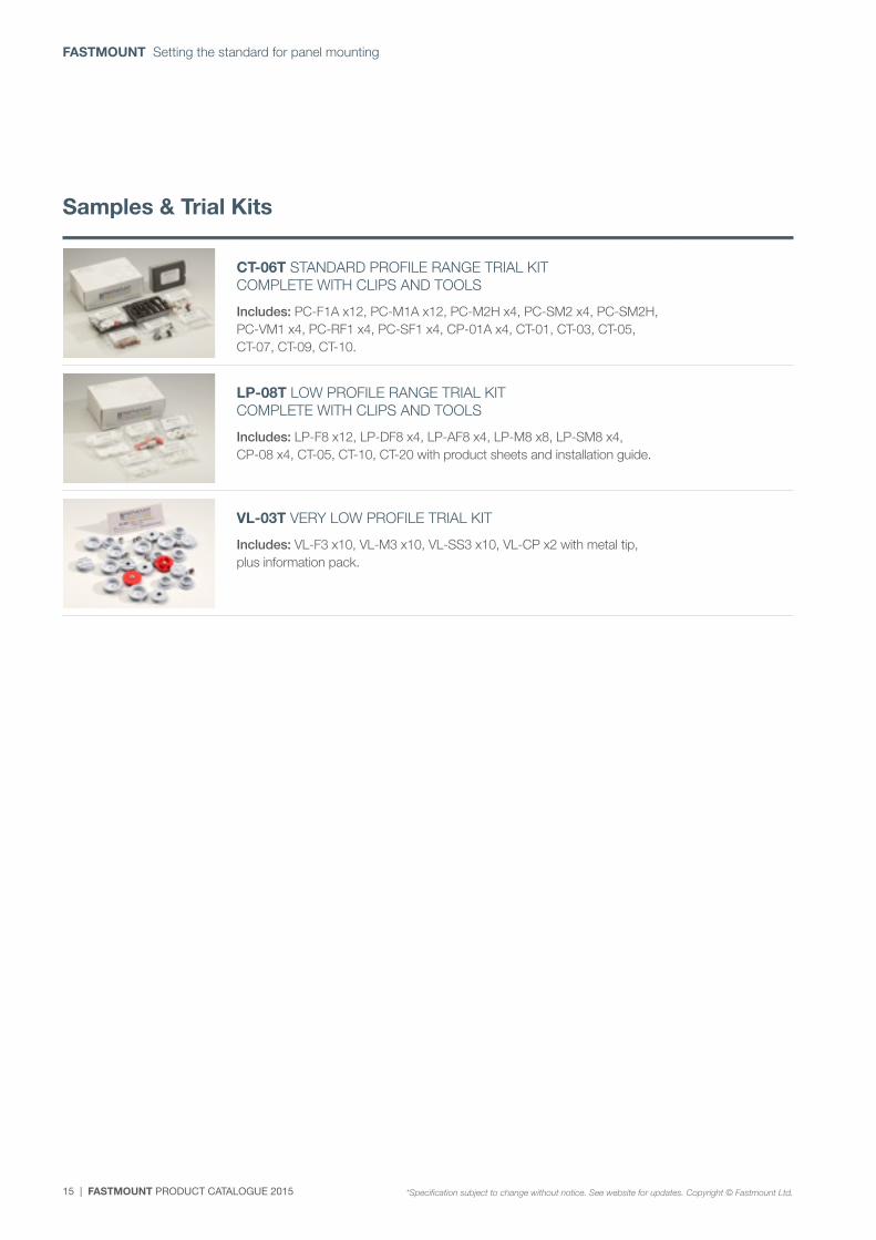
CT-06T STANDARD PROFILE RANGE TRIAL KIT COMPLETE WITH CLIPS AND TOOLS
Includes: PC-F1A x12, PC-M1A x12, PC-M2H x4, PC-SM2 x4, PC-SM2H, PC-VM1 x4, PC-RF1 x4, PC-SF1 x4, CP-01A x4, CT-01, CT-03, CT-05, CT-07, CT-09, CT-10.
LP-08T LOW PROFILE RANGE TRIAL KIT COMPLETE WITH CLIPS AND TOOLS
Includes: LP-F8 x12, LP-DF8 x4, LP-AF8 x4, LP-M8 x8, LP-SM8 x4, CP-08 x4, CT-05, CT-10, CT-20 with product sheets and installation guide.
VL-03T VERY LOW PROFILE TRIAL KIT
Includes: VL-F3 x10, VL-M3 x10, VL-SS3 x10, VL-CP x2 with metal tip, plus information pack.
Samples & Trial Kits
*Specification subject to change without notice. See website for updates. Copyright © Fastmount Ltd.
FASTMOUNT PRODUCT CATALOGUE 2015 | 16
www.fastmount.com
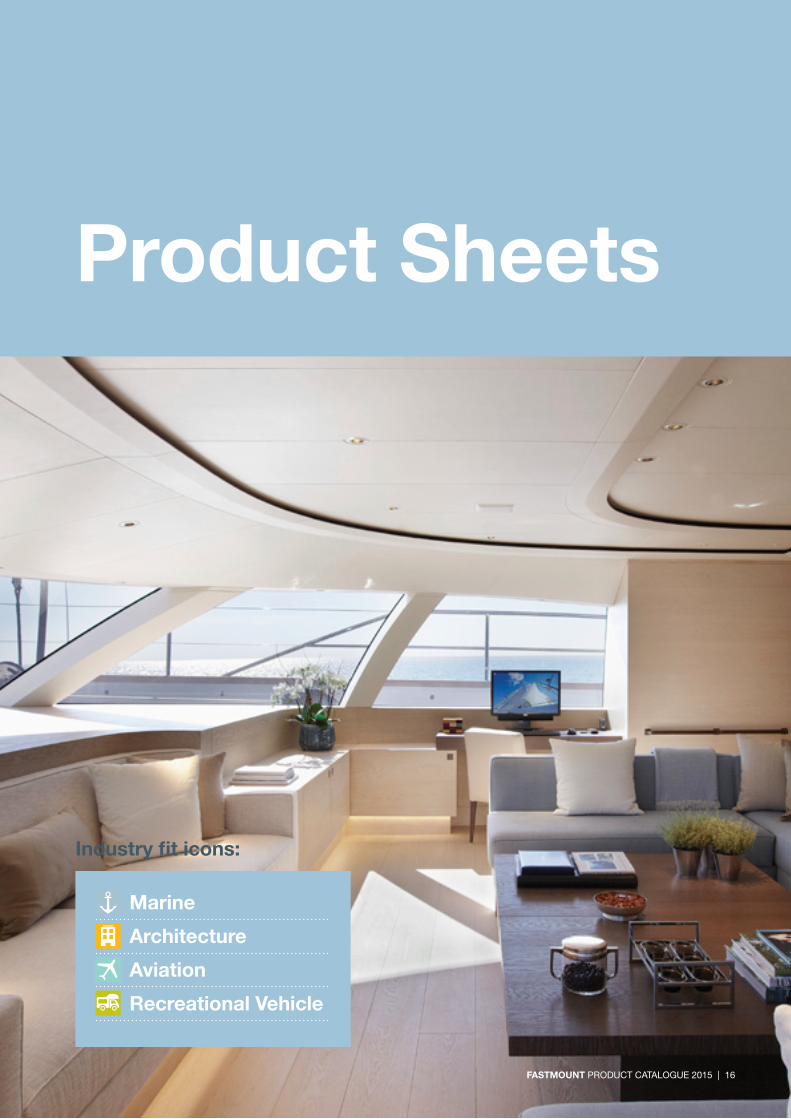
Product Sheets
Marine
Architecture
Aviation
Recreational Vehicle
Industry fit icons:
FASTMOUNT PRODUCT CATALOGUE 2015 | 16
17 | FASTMOUNT PRODUCT CATALOGUE 2015
FASTMOUNT Setting the standard for panel mounting
PC-RF1 PC-SF1 PC-SM2PC-SM2H
PC-M2H PC-VM1
SPECIFICATION: STANDARD RANGE
P. +64 21 725 418 / F. +64 9 909 6034 / E. [email protected] / Designed & Manufactured in New Zealand www.fastmount.com
INSTALLATION: Partially exploded section through showing typical installation method
PC-01 Self tapping clip set = PC-M1A + PC-F1A
*Specification subject to change without notice, see website for updates. Copyright © Fastmount Ltd.
BENEFITS
APPLICATIONS
INDUSTRY FIT:
PRODUCT SHEET PC-01 / DATE 0314
USE WITH:
MATERIAL:
MORE INFO: Installation Guide IG_PC-F1, Setout Guide TD-02
White acetal copolymer
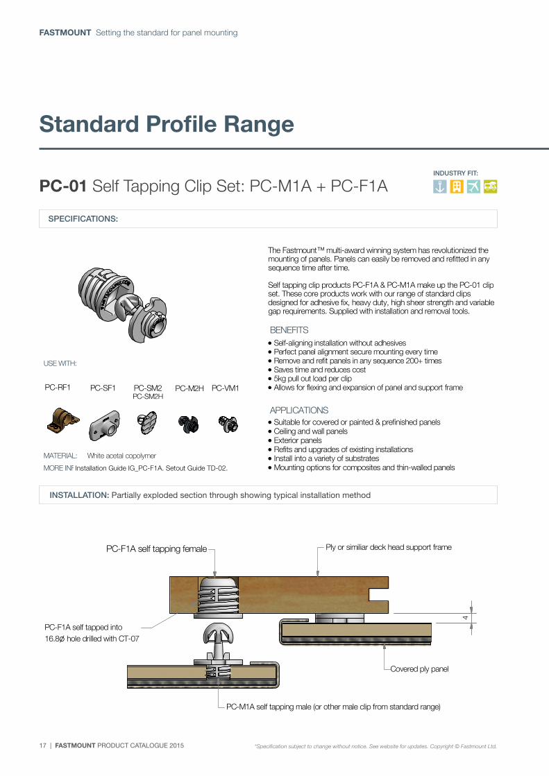
PC-F1A self tapping female Ply or similiar deck head support frame
PC-F1A self tapped into16.8 hole drilled with CT-07
Covered ply panel
PC-M1A self tapping male (or other male clip from standard range)
The Fastmount™ multi-award winning system has revolutionized the mounting of panels. Panels can easily be removed and refitted in any sequence time after time. Self tapping clip products PC-F1A & PC-M1A make up the PC-01 clip set. These core products work with our range of standard clips designed for adhesive fix, heavy duty, high sheer strength and variable gap requirements. Supplied with installation and removal tools.
Self-aligning installation without adhesives Perfect panel alignment secure mounting every time Remove and refit panels in any sequence 200+ times Saves time and reduces cost 5kg pull out load per clip Allows for flexing and expansion of panel and support frame
Suitable for covered or painted & prefinished panels Ceiling and wall panels Exterior panels Refits and upgrades of existing installations Install into a variety of substrates Mounting options for composites and thin-walled panels
4
SPECIFICATIONS:
PC-01 Self Tapping Clip Set: PC-M1A + PC-F1AINDUSTRY FIT:
INSTALLATION: Partially exploded section through showing typical installation method
Installation Guide IG_PC-F1A. Setout Guide TD-02.
Standard Profile Range
*Specification subject to change without notice. See website for updates. Copyright © Fastmount Ltd.
FASTMOUNT PRODUCT CATALOGUE 2015 | 18
www.fastmount.com
PC-RF1 PC-SF1PC-F1
SPECIFICATION: STANDARD RANGE
P. +64 21 725 418 / F. +64 9 909 6034 / E. [email protected] / Designed & Manufactured in New Zealand www.fastmount.com
INSTALLATION: Partially exploded section through showing typical installation method
PC-M2H Self tapping male heavy duty
*Specification subject to change without notice, see website for updates. Copyright © Fastmount Ltd.
BENEFITS
APPLICATIONS
INDUSTRY FIT:
PRODUCT SHEET PC-M2H / DATE 0911
USE WITH:
MATERIAL:
MORE INFO: Installation Guide IG_PC-F1, SF1, RF1, Setout Guide TD-02
Black acetal copolymer
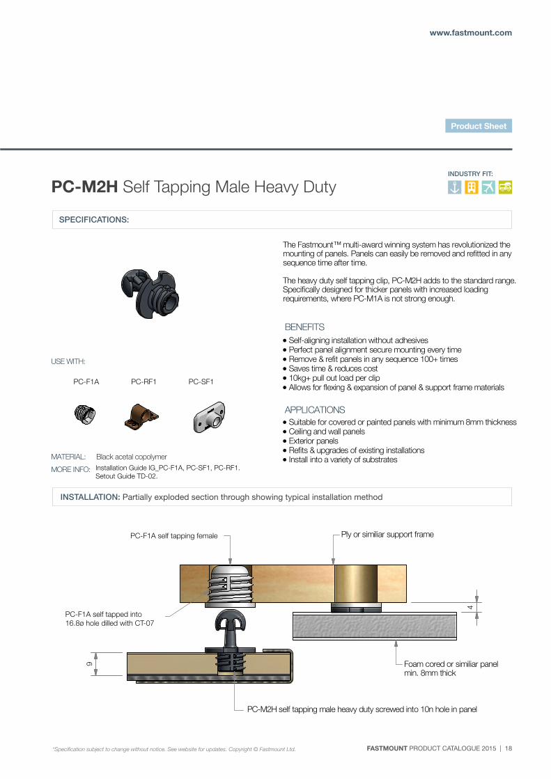
The Fastmount™ multi-award winning system has revolutionized the mounting of panels. Panels can easily be removed and refitted in any sequence time after time. The heavy duty self tapping clip, PC-M2H adds to the standard range. Specifically designed for thicker panels with increased loading requirements, where PC-M1A is not strong enough.
Self-aligning installation without adhesives Perfect panel alignment secure mounting every time Remove & refit panels in any sequence 100+ times Saves time & reduces cost 10kg+ pull out load per clip Allows for flexing & expansion of panel & support frame materials Suitable for covered or painted panels with minimum 8mm thickness Ceiling and wall panels Exterior panels Refits & upgrades of existing installations Install into a variety of substrates
PC-F1 self tapping female Ply or similiar support frame
PC-F1 self tapped into
16.8 hole drilled with CT-07
Foam cored or similiar panelmin. 8mm thick
PC-M2H self tapping male heavy duty screwed into 10n hole in panel
4
9
SPECIFICATIONS:
PC-M2H Self Tapping Male Heavy DutyINDUSTRY FIT:
INSTALLATION: Partially exploded section through showing typical installation method
Installation Guide IG_PC-F1A, PC-SF1, PC-RF1. Setout Guide TD-02.
PC-F1A self tapping female
PC-F1A self tapped into 16.8ø hole dilled with CT-07
PC-F1A PC-RF1 PC-SF1
*Specification subject to change without notice. See website for updates. Copyright © Fastmount Ltd.
Product Sheet
19 | FASTMOUNT PRODUCT CATALOGUE 2015
FASTMOUNT Setting the standard for panel mounting
PC-RF1 PC-SF1PC-F1 PC-AF1
B ( 1 : 2 )
B
SPECIFICATION: STANDARD RANGE
P. +64 21 725 418 / F. +64 9 909 6034 / E. [email protected] / Designed & Manufactured in New Zealand www.fastmount.com
INSTALLATION: Partially exploded section through showing typical installation method
PC-VM1 Vario Clip self tapping male
*Specification subject to change without notice, see website for updates. Copyright © Fastmount Ltd.
BENEFITS
APPLICATIONS
INDUSTRY FIT:
PRODUCT SHEET PC-VM1 / DATE 0314
USE WITH:
MATERIAL:
MORE INFO: Installation Guide IG_PC-F1,SF1,RF1, Setout Guide TD-02
White acetal copolymer
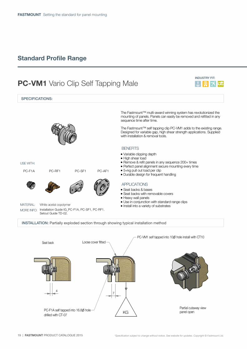
The Fastmount™ multi-award winning system has revolutionized the mounting of panels. Panels can easily be removed and refitted in any sequence time after time. The Fastmount™ self tapping clip PC-VM1 adds to the existing range. Designed for variable gap, high shear strength applications. Supplied with installation & removal tools.
Variable clipping depth High shear load Remove & refit panels in any sequence 200+ times Perfect panel alignment secure mounting every time 5+kg pull out load per clip Durable design for frequent handling
Seat backs & bases Seat backs with removable covers Heavy wall panels Use in conjunction with standard range clips Install into a variety of substrates
PC-VM1 self tapped into 10 hole install with CT10
PC-F1A self tapped into 16.8 holedrilled with CT-07
Loose cover fitted
Partial cutaway viewpanel open
Seat back
KG
74
SPECIFICATIONS:
PC-VM1 Vario Clip Self Tapping Male
INSTALLATION: Partially exploded section through showing typical installation method
PC-F1A PC-RF1 PC-SF1 PC-AF1
Installation Guide IG_PC-F1A, PC-SF1, PC-RF1. Setout Guide TD-02.
Standard Profile Range
*Specification subject to change without notice. See website for updates. Copyright © Fastmount Ltd.
INDUSTRY FIT:
FASTMOUNT PRODUCT CATALOGUE 2015 | 20
www.fastmount.com
PC-RF1 PC-SF1PC-F1
A ( 2 : 1 )
A
SPECIFICATION: STANDARD RANGE
P. +64 21 725 418 / F. +64 9 909 6034 / E. [email protected] / Designed & Manufactured in New Zealand www.fastmount.com
INSTALLATION: Partially exploded section through showing typical installation method
PC-SM2 Surface mount male adhesive fix
*Specification subject to change without notice, see website for updates. Copyright © Fastmount Ltd.
BENEFITS
APPLICATIONS
INDUSTRY FIT:
PRODUCT SHEET PC-SM2 / DATE 0911
USE WITH:
MATERIAL:
MORE INFO: Installation Guide IG_PC-F1, SF1, RF1, Setout Guide TD-02
White acetal copolymer
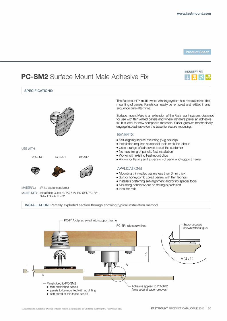
The Fastmount™ multi-award winning system has revolutionized the mounting of panels. Panels can easily be removed and refitted in any sequence time after time. Surface mount Male is an extension of the Fastmount system, designedfor use with thin walled panels and where installers prefer an adhesive fix. It is ideal for new composite materials. Super-grooves mechanically engage into adhesive on the base for secure mounting.
Self-aligning secure mounting (5kg per clip) Installation requires no special tools or skilled labour Uses a range of adhesives to suit the customer No machining of panels, fast installation Works with existing Fastmount clips Allows for flexing and expansion of panel and support frame
Mounting thin walled panels less than 6mm thick Soft or honeycomb cored panels with thin facings Installers preferring self-alignment and/or no special tools Mounting panels where no drilling is preferred Ideal for refit
PC-F1 clip screwed into support frame
PC-SF1 clip screw fixed Super-groovesshown without glue
Adhesive applied to PC-SM2flows around super-grooves
Panel glued to PC-SM2● thin prefinished panels● panels to be mounted with no drilling● soft cored or thin faced panels
15
SPECIFICATIONS:
PC-SM2 Surface Mount Male Adhesive Fix
INSTALLATION: Partially exploded section through showing typical installation method
Installation Guide IG_PC-F1A, PC-SF1, PC-RF1. Setout Guide TD-02.
PC-F1A clip screwed into support frame
PC-F1A PC-RF1 PC-SF1
*Specification subject to change without notice. See website for updates. Copyright © Fastmount Ltd.
INDUSTRY FIT:
Product Sheet
21 | FASTMOUNT PRODUCT CATALOGUE 2015
FASTMOUNT Setting the standard for panel mounting
PC-RF1 PC-SF1PC-F1
B ( 2 : 1 )
B
SPECIFICATION: STANDARD RANGE
P. +64 21 725 418 / F. +64 9 909 6034 / E. [email protected] / Designed & Manufactured in New Zealand www.fastmount.com
INSTALLATION: Partially exploded section through showing typical installation method
PC-SM2H Surface mount male adhesive fix
*Specification subject to change without notice, see website for updates. Copyright © Fastmount Ltd.
BENEFITS
APPLICATIONS
INDUSTRY FIT:
PRODUCT SHEET PC-SM2H / DATE 0911
USE WITH:
MATERIAL:
MORE INFO: Installation Guide IG_PC-F1, SF1, RF1, Setout Guide TD-02
Back acetal copolymer
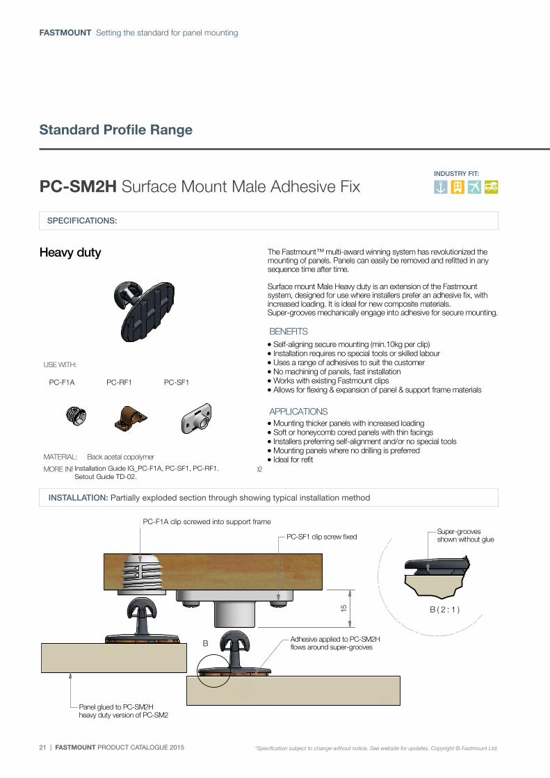
The Fastmount™ multi-award winning system has revolutionized the mounting of panels. Panels can easily be removed and refitted in any sequence time after time. Surface mount Male Heavy duty is an extension of the Fastmount system, designed for use where installers prefer an adhesive fix, with increased loading. It is ideal for new composite materials. Super-grooves mechanically engage into adhesive for secure mounting.
Self-aligning secure mounting (min.10kg per clip) Installation requires no special tools or skilled labour Uses a range of adhesives to suit the customer No machining of panels, fast installation Works with existing Fastmount clips Allows for flexing & expansion of panel & support frame materials Mounting thicker panels with increased loading Soft or honeycomb cored panels with thin facings Installers preferring self-alignment and/or no special tools Mounting panels where no drilling is preferred Ideal for refit
Heavy duty
Adhesive applied to PC-SM2Hflows around super-grooves
Panel glued to PC-SM2Hheavy duty version of PC-SM2
PC-F1 clip screwed into support frame
PC-SF1 clip screw fixedSuper-groovesshown without glue
15
SPECIFICATIONS:
PC-SM2H Surface Mount Male Adhesive Fix
INSTALLATION: Partially exploded section through showing typical installation method
PC-F1A PC-RF1 PC-SF1
Installation Guide IG_PC-F1A, PC-SF1, PC-RF1. Setout Guide TD-02.
PC-F1A clip screwed into support frame
Standard Profile Range
*Specification subject to change without notice. See website for updates. Copyright © Fastmount Ltd.
INDUSTRY FIT:
FASTMOUNT PRODUCT CATALOGUE 2015 | 22
www.fastmount.com
PC-SM2
PC-M2H
PC-M1A
PC-SM2H
PC-VM1
SPECIFICATION: STANDARD RANGE
P. +64 21 725 418 / F. +64 9 909 6034 / E. [email protected] / Designed & Manufactured in New Zealand www.fastmount.com
INSTALLATION: Partially exploded section through showing typical installation method
PC-SF1 Surface mount female screw fix
*Specification subject to change without notice, see website for updates. Copyright © Fastmount Ltd.
BENEFITS
APPLICATIONS
INDUSTRY FIT:
PRODUCT SHEET PC-SF1 / DATE 1214
USE WITH:
MATERIAL:
MORE INFO: Installation Guide IG_PC-SF1, Setout Guide TD-02
White acetal copolymer
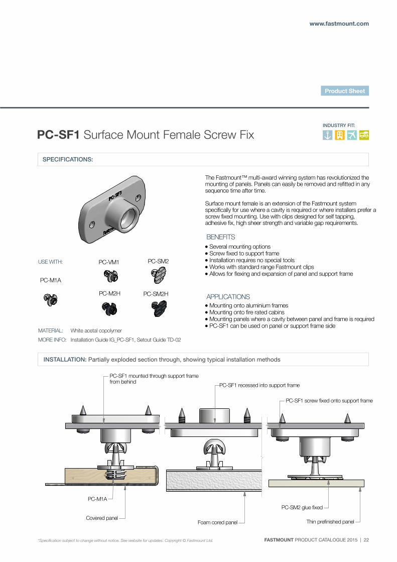
The Fastmount™ multi-award winning system has revolutionized the mounting of panels. Panels can easily be removed and refitted in any sequence time after time. Surface mount female is an extension of the Fastmount system specifically for use where a cavity is required or where installers prefer ascrew fixed mounting. Use with clips designed for self tapping, adhesive fix, high sheer strength and variable gap requirements.
Several mounting options Screw fixed to support frame Installation requires no special tools Works with standard range Fastmount clips Allows for flexing and expansion of panel and support frame
Mounting onto aluminium frames Mounting onto fire rated cabins Mounting panels where a cavity between panel and frame is required PC-SF1 can be used on panel or support frame side
PC-SF1 mounted through support framefrom behind
PC-SM2 glue fixed
PC-M1A
Foam cored panel Thin prefinished panel
PC-SF1 recessed into support frame
PC-SF1 screw fixed onto support frame
Covered panel
SPECIFICATIONS:
PC-SF1 Surface Mount Female Screw Fix
INSTALLATION: Partially exploded section through, showing typical installation methods
*Specification subject to change without notice. See website for updates. Copyright © Fastmount Ltd.
INDUSTRY FIT:
Product Sheet
23 | FASTMOUNT PRODUCT CATALOGUE 2015
FASTMOUNT Setting the standard for panel mounting
PC-SM2
PC-M2H
PC-M1A
PC-SM2H
PC-VM1
SPECIFICATION: STANDARD RANGE
P. +64 21 725 418 / F. +64 9 909 6034 / E. [email protected] / Designed & Manufactured in New Zealand www.fastmount.com
INSTALLATION: Partially exploded section through showing typical installation method
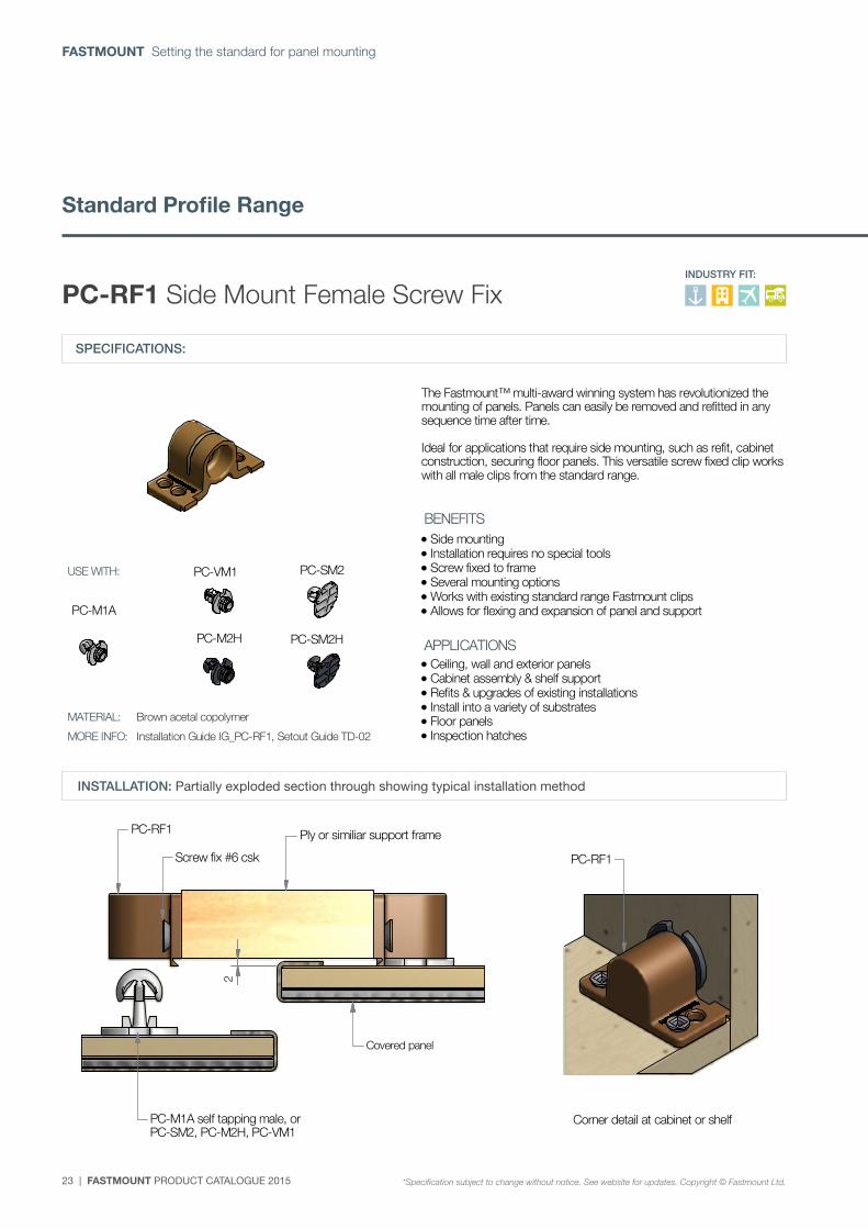
PC-RF1 Side mount female screw fix
*Specification subject to change without notice, see website for updates. Copyright © Fastmount Ltd.
BENEFITS
APPLICATIONS
INDUSTRY FIT:
PRODUCT SHEET PC-RF1 / DATE 0314
USE WITH:
MATERIAL:
MORE INFO: Installation Guide IG_PC-RF1, Setout Guide TD-02
Brown acetal copolymer
The Fastmount™ multi-award winning system has revolutionized the mounting of panels. Panels can easily be removed and refitted in any sequence time after time. Ideal for applications that require side mounting, such as refit, cabinet construction, securing floor panels. This versatile screw fixed clip workswith all male clips from the standard range.
Side mounting Installation requires no special tools Screw fixed to frame Several mounting options Works with existing standard range Fastmount clips Allows for flexing and expansion of panel and support Ceiling, wall and exterior panels Cabinet assembly & shelf support Refits & upgrades of existing installations Install into a variety of substrates Floor panels Inspection hatches
PC-M1A self tapping male, orPC-SM2, PC-M2H, PC-VM1
Covered panel
Ply or similiar support frame
Screw fix #6 csk
PC-RF1
PC-RF1
Corner detail at cabinet or shelf
2
SPECIFICATIONS:
PC-RF1 Side Mount Female Screw Fix
INSTALLATION: Partially exploded section through showing typical installation method
Standard Profile Range
*Specification subject to change without notice. See website for updates. Copyright © Fastmount Ltd.
INDUSTRY FIT:
FASTMOUNT PRODUCT CATALOGUE 2015 | 24
www.fastmount.com
PC-SM2
PC-M2H
PC-M1A
PC-SM2H
PC-VM1
SPECIFICATION: STANDARD RANGE
P. +64 21 725 418 / F. +64 9 909 6034 / E. [email protected] / Designed & Manufactured in New Zealand www.fastmount.com
INSTALLATION: Partially exploded section through showing typical installation method
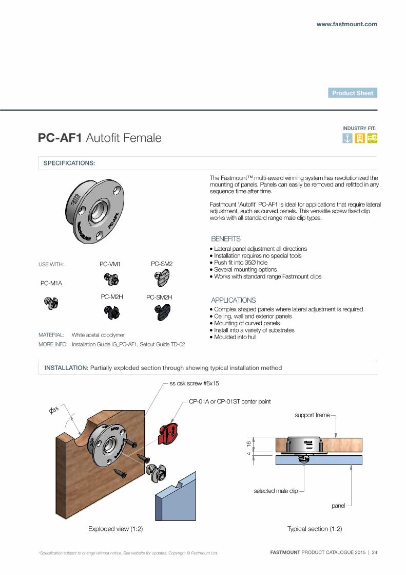
PC-AF1 Autofit female
*Specification subject to change without notice, see website for updates. Copyright © Fastmount Ltd.
BENEFITS
APPLICATIONS
INDUSTRY FIT:
PRODUCT SHEET PC-AF1 / DATE 0314
USE WITH:
MATERIAL:
MORE INFO: Installation Guide IG_PC-AF1, Setout Guide TD-02
White acetal copolymer
The Fastmount™ multi-award winning system has revolutionized the mounting of panels. Panels can easily be removed and refitted in any sequence time after time. Fastmount 'Autofit' PC-AF1 is ideal for applications that require lateral adjustment, such as curved panels. This versatile screw fixed clip works with all standard range male clip types.
Lateral panel adjustment all directions Installation requires no special tools Push fit into 35Ø hole Several mounting options Works with standard range Fastmount clips
Complex shaped panels where lateral adjustment is required Ceiling, wall and exterior panels Mounting of curved panels Install into a variety of substrates Moulded into hull
ss csk screw #6x15
35CP-01A or CP-01ST center point
selected male clip
support frame
panel
164
Exploded view (1:2) Typical section (1:2)
SPECIFICATIONS:
PC-AF1 Autofit Female
INSTALLATION: Partially exploded section through showing typical installation method
Exploded view (1:2) Typical section (1:2)
*Specification subject to change without notice. See website for updates. Copyright © Fastmount Ltd.
INDUSTRY FIT:
Product Sheet
25 | FASTMOUNT PRODUCT CATALOGUE 2015
FASTMOUNT Setting the standard for panel mounting
LP-M8 LP-SM8
SPECIFICATION: LOW PROFILE RANGE
P. +64 21 725 418 / F. +64 9 909 6034 / E. [email protected] / Designed & Manufactured in New Zealand www.fastmount.com
INSTALLATION: Partially exploded section through showing typical installation method
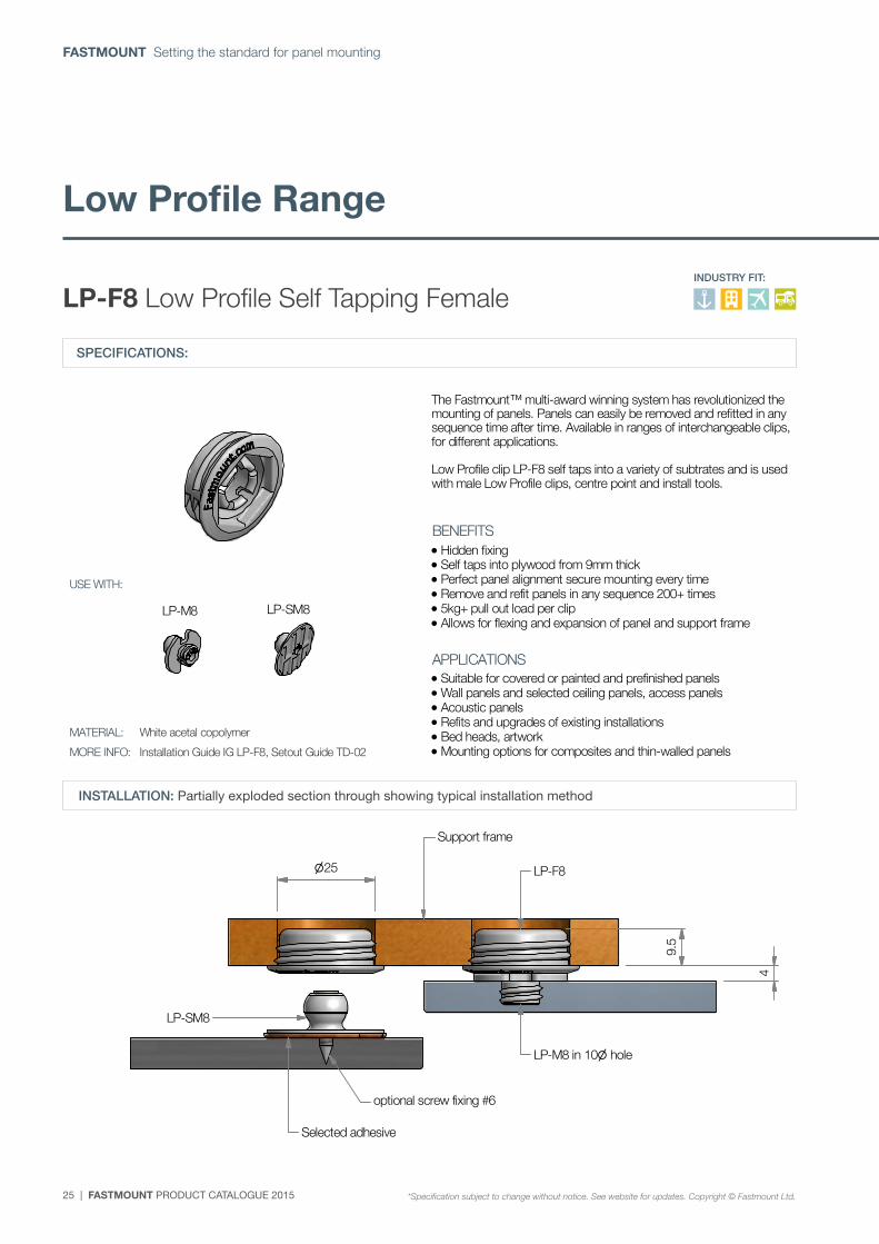
LP-F8 Low Profile self tapping female
*Specification subject to change without notice, see website for updates. Copyright © Fastmount Ltd.
BENEFITS
APPLICATIONS
INDUSTRY FIT:
PRODUCT SHEET LP-F8 / DATE 0812
USE WITH:
MATERIAL:
MORE INFO: Installation Guide IG LP-F8, Setout Guide TD-02
White acetal copolymer
The Fastmount™ multi-award winning system has revolutionized the mounting of panels. Panels can easily be removed and refitted in any sequence time after time. Available in ranges of interchangeable clips, for different applications. Low Profile clip LP-F8 self taps into a variety of subtrates and is used with male Low Profile clips, centre point and install tools.
Hidden fixing Self taps into plywood from 9mm thick Perfect panel alignment secure mounting every time Remove and refit panels in any sequence 200+ times 5kg+ pull out load per clip Allows for flexing and expansion of panel and support frame
Suitable for covered or painted and prefinished panels Wall panels and selected ceiling panels, access panels Acoustic panels Refits and upgrades of existing installations Bed heads, artwork Mounting options for composites and thin-walled panels
4
25 LP-F8
Support frame
LP-M8 in 10 hole
optional screw fixing #6
Selected adhesive
LP-SM8
9.5
SPECIFICATIONS:
LP-F8 Low Profile Self Tapping Female
INSTALLATION: Partially exploded section through showing typical installation method
Low Profile Range
*Specification subject to change without notice. See website for updates. Copyright © Fastmount Ltd.
INDUSTRY FIT:
FASTMOUNT PRODUCT CATALOGUE 2015 | 26
www.fastmount.com
LP-M8 LP-SM8
E ( 1 : 2 )
E
SPECIFICATION: LOW PROFILE RANGE
P. +64 21 725 418 / F. +64 9 909 6034 / E. [email protected] / Designed & Manufactured in New Zealand www.fastmount.com
INSTALLATION: Partially exploded section through showing typical installation method
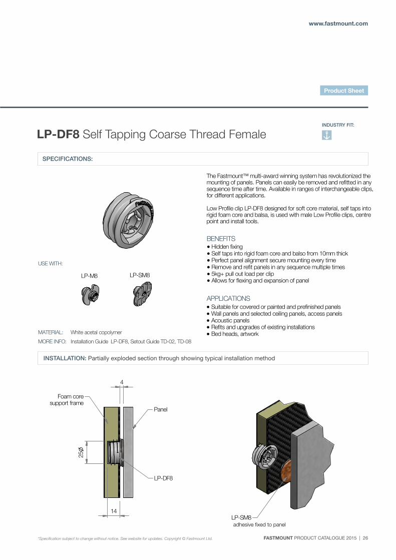
LP-DF8 Self tapping coarse thread female
*Specification subject to change without notice, see website for updates. Copyright © Fastmount Ltd.
BENEFITS
APPLICATIONS
INDUSTRY FIT:
PRODUCT SHEET LP-DF8 / DATE 0812
USE WITH:
MATERIAL:
MORE INFO: Installation Guide LP-DF8, Setout Guide TD-02, TD-08
White acetal copolymer
(Page 2 of 2)
The Fastmount™ multi-award winning system has revolutionized the mounting of panels. Panels can easily be removed and refitted in any sequence time after time. Available in ranges of interchangeable clips, for different applications. Low Profile clip LP-DF8 designed for soft core material, self taps into rigid foam core and balsa, is used with male Low Profile clips, centre point and install tools.
Hidden fixing Self taps into rigid foam core and balso from 10mm thick Perfect panel alignment secure mounting every time Remove and refit panels in any sequence multiple times 5kg+ pull out load per clip Allows for flexing and expansion of panel
Suitable for covered or painted and prefinished panels Wall panels and selected ceiling panels, access panels Acoustic panels Refits and upgrades of existing installations Bed heads, artwork
4
14
25
Panel
Foam coresupport frame
LP-DF8
LP-SM8adhesive fixed to panel
SPECIFICATIONS:
LP-DF8 Self Tapping Coarse Thread Female
INSTALLATION: Partially exploded section through showing typical installation method
adhesive fixed to panel
*Specification subject to change without notice. See website for updates. Copyright © Fastmount Ltd.
INDUSTRY FIT:
Product Sheet
27 | FASTMOUNT PRODUCT CATALOGUE 2015
FASTMOUNT Setting the standard for panel mounting
LP-M8 LP-SM8
A
D
SPECIFICATION: LOW PROFILE RANGE
P. +64 21 725 418 / F. +64 9 909 6034 / E. [email protected] / Designed & Manufactured in New Zealand www.fastmount.com
INSTALLATION: Partially exploded section through showing typical installation method
LP-DF8 Self tapping coarse thread female
*Specification subject to change without notice, see website for updates. Copyright © Fastmount Ltd.
BENEFITS
APPLICATIONS
INDUSTRY FIT:
PRODUCT SHEET LP-DF8 / DATE 0812
USE WITH:
MATERIAL:
MORE INFO: Installation Guide LP-DF8, Setout Guide TD-02, TD-08
White acetal copolymer
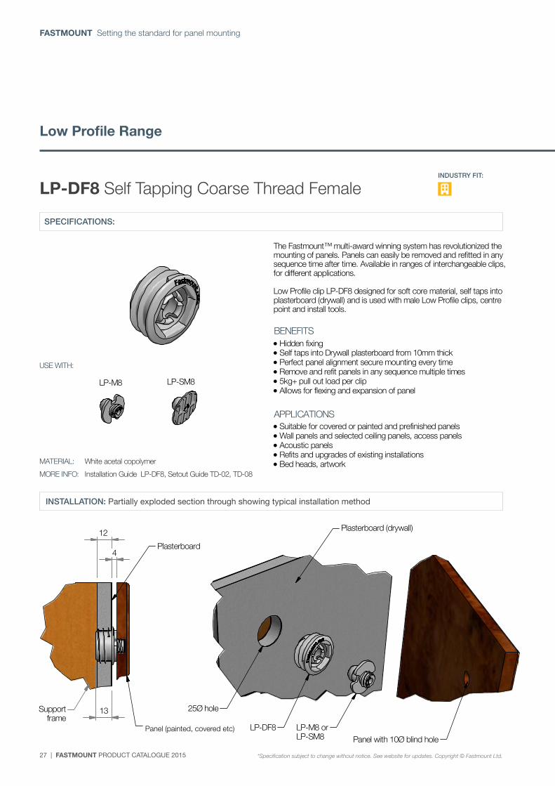
The Fastmount™ multi-award winning system has revolutionized the mounting of panels. Panels can easily be removed and refitted in any sequence time after time. Available in ranges of interchangeable clips, for different applications. Low Profile clip LP-DF8 designed for soft core material, self taps into plasterboard (drywall) and is used with male Low Profile clips, centre point and install tools.
Hidden fixing Self taps into Drywall plasterboard from 10mm thick Perfect panel alignment secure mounting every time Remove and refit panels in any sequence multiple times 5kg+ pull out load per clip Allows for flexing and expansion of panel
Suitable for covered or painted and prefinished panels Wall panels and selected ceiling panels, access panels Acoustic panels Refits and upgrades of existing installations Bed heads, artwork
NEW PRODUCT
12
4
Panel(painted, covered etc.)
Plasterboard
LP-DF8 LP-M8 orLP-SM8
13
Panel with 10Ø blind hole
25Ø holeSupportframe
Plasterboard (drywall)
(Page 1 of 2)SPECIFICATIONS:
LP-DF8 Self Tapping Coarse Thread Female
INSTALLATION: Partially exploded section through showing typical installation method
Panel (painted, covered etc)
Low Profile Range
*Specification subject to change without notice. See website for updates. Copyright © Fastmount Ltd.
INDUSTRY FIT:
FASTMOUNT PRODUCT CATALOGUE 2015 | 28
www.fastmount.com
LP-M8 LP-SM8
SPECIFICATION: LOW PROFILE RANGE
P. +64 21 725 418 / F. +64 9 909 6034 / E. [email protected] / Designed & Manufactured in New Zealand www.fastmount.com
INSTALLATION: Partially exploded section through showing typical installation method
LP-AF8 Low Profile Autofit female
*Specification subject to change without notice, see website for updates. Copyright © Fastmount Ltd.
BENEFITS
APPLICATIONS
INDUSTRY FIT:
PRODUCT SHEET LP-AF8 / DATE 1111
USE WITH:
MATERIAL:
MORE INFO: Installation Guide IG LP-AF8, Setout Guide TD-02
White acetal copolymer
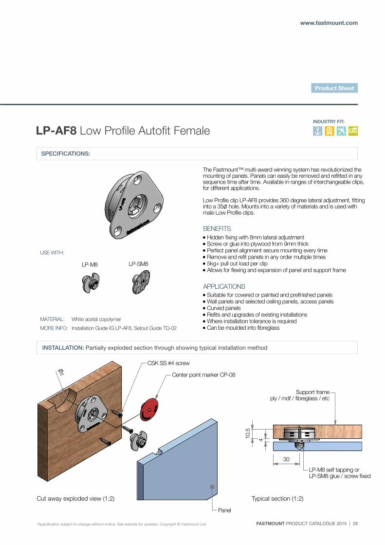
The Fastmount™ multi-award winning system has revolutionized the mounting of panels. Panels can easily be removed and refitted in any sequence time after time. Available in ranges of interchangeable clips, for different applications. Low Profile clip LP-AF8 provides 360 degree lateral adjustment, fitting into a 35 hole. Mounts into a variety of materials and is used with male Low Profile clips.
Hidden fixing with 8mm lateral adjustment Screw or glue into plywood from 9mm thick Perfect panel alignment secure mounting every time Remove and refit panels in any order multiple times 5kg+ pull out load per clip Allows for flexing and expansion of panel and support frame
Suitable for covered or painted and prefinished panels Wall panels and selected ceiling panels, access panels Curved panels Refits and upgrades of existing installations Where installation tolerance is required Can be moulded into fibreglass
NEW PRODUCT
10.5
4
30
Cut away exploded view (1:2)
Center point marker CP-08
CSK SS #4 screw
LP-M8 self tapping orLP-SM8 glue / screw fixed
Panel Typical section (1:2)
35
Support frameply / mdf / fibreglass / etc
SPECIFICATIONS:
LP-AF8 Low Profile Autofit Female
INSTALLATION: Partially exploded section through showing typical installation method
Cut away exploded view (1:2) Typical section (1:2)
*Specification subject to change without notice. See website for updates. Copyright © Fastmount Ltd.
INDUSTRY FIT:
Product Sheet
29 | FASTMOUNT PRODUCT CATALOGUE 2015
FASTMOUNT Setting the standard for panel mounting
SPECIFICATION: VERY LOW PROFILE RANGE
P. +64 21 725 418 / F. +64 9 909 6034 / E. [email protected] / Designed & Manufactured in New Zealand www.fastmount.com
INSTALLATION: Partially exploded section through showing typical installation method
VL-03 Very Low Profile clip set VL-F3+M3+SS3
*Specification subject to change without notice, see website for updates. Copyright © Fastmount Ltd.
BENEFITS
APPLICATIONS
INDUSTRY FIT:
PRODUCT SHEET VL-03 / DATE 0314
USE WITH:
MATERIAL:
MORE INFO: Installation Guide IG VL-03, Setout Guide TD-02
Grey acetal copolymer
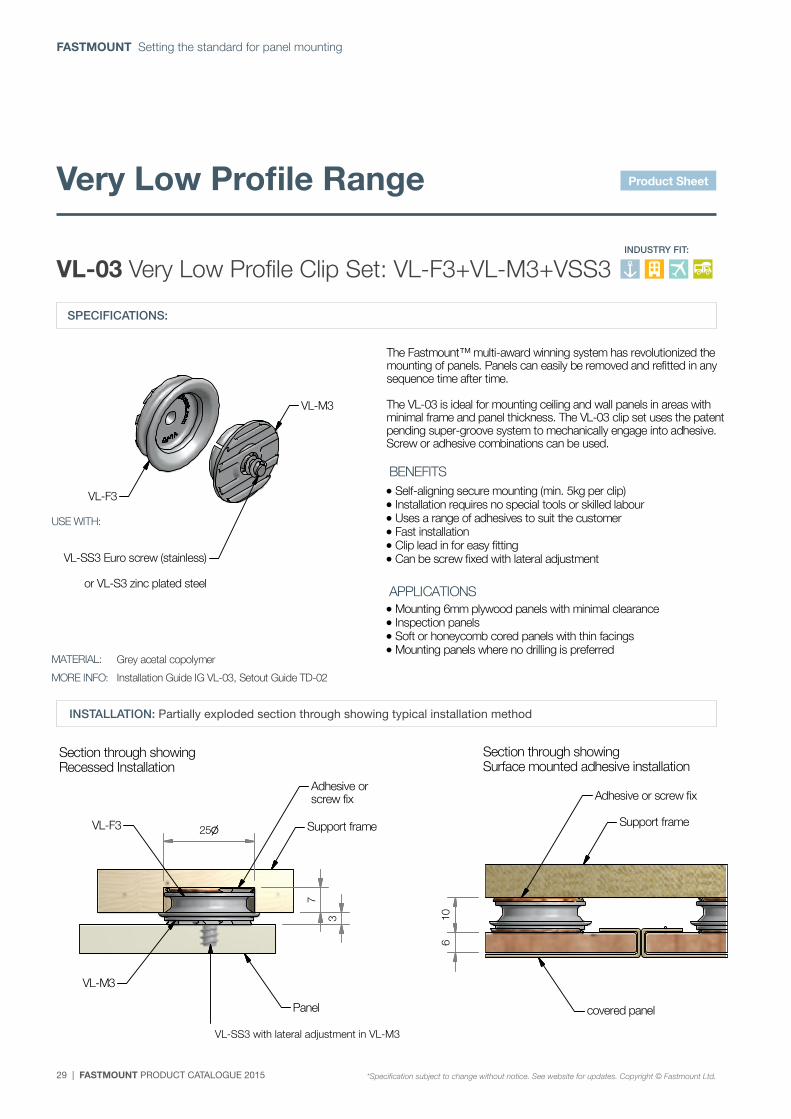
The Fastmount™ multi-award winning system has revolutionized the mounting of panels. Panels can easily be removed and refitted in any sequence time after time. The VL-03 is ideal for mounting ceiling and wall panels in areas with minimal frame and panel thickness. The VL-03 clip set uses the patent pending super-groove system to mechanically engage into adhesive. Screw or adhesive combinations can be used.
Self-aligning secure mounting (min. 5kg per clip) Installation requires no special tools or skilled labour Uses a range of adhesives to suit the customer Fast installation Clip lead in for easy fitting Can be screw fixed with lateral adjustment
Mounting 6mm plywood panels with minimal clearance Inspection panels Soft or honeycomb cored panels with thin facings Mounting panels where no drilling is preferred
Section through showingRecessed Installation
10
Section through showingSurface mounted adhesive installation
Support frame
Adhesive or screw fix
VL-SS3 Euro screw (stainless)
or VL-S3 zinc plated steel
VL-F3
VL-M3
6
3
7
25 Support frameVL-F3
VL-M3
VL-SS3with lateral adjustment in VL-M3
Adhesive orscrew fix
covered panelPanel
SPECIFICATIONS:
VL-03 Very Low Profile Clip Set: VL-F3+VL-M3+VSS3
INSTALLATION: Partially exploded section through showing typical installation method
VL-SS3 with lateral adjustment in VL-M3
Very Low Profile Range
*Specification subject to change without notice. See website for updates. Copyright © Fastmount Ltd.
INDUSTRY FIT:
Product Sheet
FASTMOUNT PRODUCT CATALOGUE 2015 | 30
www.fastmount.com
SPECIFICATION: METAL RANGE
P. +64 21 725 418 / F. +64 9 909 6034 / E. [email protected] / Designed & Manufactured in New Zealand www.fastmount.com
INSTALLATION: Partially exploded section through showing typical installation method
MC-05 Maxi Metal Clip Set MC-F5+MC-M5H
*Specification subject to change without notice, see website for updates. Copyright © Fastmount Ltd.
BENEFITS
APPLICATIONS
INDUSTRY FIT:
PRODUCT SHEET MC-05 / DATE 0314
USE WITH:
MATERIAL:
MORE INFO: Installation Guide IG_MC-05, Setout Guide TD-02
EZDA 3 with duplex finish, SS spring
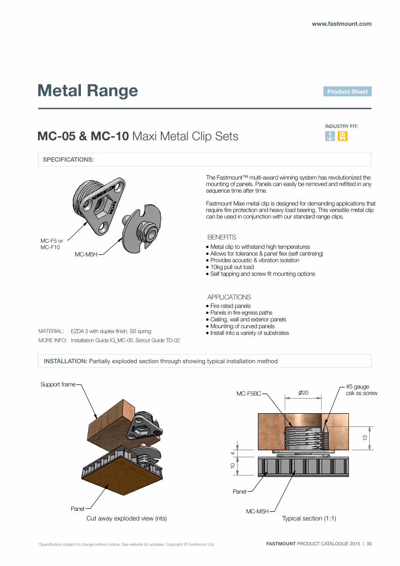
The Fastmount™ multi-award winning system has revolutionized the mounting of panels. Panels can easily be removed and refitted in any sequence time after time. Fastmount Maxi metal clip is designed for demanding applications that require fire protection and heavy load bearing. This versatile metal clip can be used in conjunction with our standard range clips.
Metal clip to withstand high temperatures Allows for tolerance & panel flex (self centreing) Provides acoustic & vibration isolation 10kg pull out load Self tapping and screw fit mounting options
Fire rated panels Panels in fire egress paths Ceiling, wall and exterior panels Mounting of curved panels Install into a variety of substrates
Cutaway exploded view (nts) Typical section (1:1)
410
13
20
Support frame
Panel
Panel
MC-M5H
MC-F5BC#5 gaugecsk ss screw
MC-F5
MC-M5H
SPECIFICATIONS:
MC-05 & MC-10 Maxi Metal Clip Sets
INSTALLATION: Partially exploded section through showing typical installation method
MC-F5 or MC-F10
Cut away exploded view (nts) Typical section (1:1)
Metal Range
*Specification subject to change without notice. See website for updates. Copyright © Fastmount Ltd.
INDUSTRY FIT:
Product Sheet
31 | FASTMOUNT PRODUCT CATALOGUE 2015
FASTMOUNT Setting the standard for panel mounting
PC-01
B ( 1 : 2.5 )B
SPECIFICATION: STANDARD RANGE
P. +64 21 725 418 / F. +64 9 909 6034 / E. [email protected] / Designed & Manufactured in New Zealand www.fastmount.com
INSTALLATION: Partially exploded section through showing typical installation method
PS-150E PanelSafe Easy fit - self tapping
*Specification subject to change without notice, see website for updates. Copyright © Fastmount Ltd.
BENEFITS
APPLICATIONS
INDUSTRY FIT:
PRODUCT SHEET PS-150E / DATE 1214
USE WITH:
MATERIAL:
MORE INFO: Installation Guide IG PS-150E, Setout Guide IG PS-150E/2
Aluminium & stainless steel
The Fastmount™ multi-award winning system has revolutionized the mounting of panels. Panels can easily be removed and refitted in any sequence time after time. PanelSafe Easy fit restraint systems provide added security & control. The panel is suspended below the ceiling for convenient servicing behind the panel or controlled removal of the panel by releasing the wire. For use with fastmount system clips & installation tools.
Secures heavy panels Easy one person removal of large panels Convenient servicing behind panel without full removal Prevents panels falling during fire exit Works with existing Fastmount clips Variable length to suit application
Inspection & service panels Panels above valuable furniture and artwork Surface mount option available Heavy panels Large panels
Standard 150mm drop, custom lengths available on request
Cut away view panel openSupport frame
SS wire, selected length
4
Panel with Fastmount
PS-150E self tapping base
Foam pad
SS screw release
Clearance holemin. 10
SPECIFICATIONS:
PS-150E PanelSafe Easy Fit – Self Tapping
INSTALLATION: Partially exploded section through showing typical installation method
PS-150E Self Tap Base
*Specification subject to change without notice. See website for updates. Copyright © Fastmount Ltd.
Panel Control Range
INDUSTRY FIT:
FASTMOUNT PRODUCT CATALOGUE 2015 | 32
www.fastmount.com
PC-01
C ( 1 : 3 )
C
SPECIFICATION: STANDARD RANGE
P. +64 21 725 418 / F. +64 9 909 6034 / E. [email protected] / Designed & Manufactured in New Zealand www.fastmount.com
INSTALLATION: Partially exploded section through showing typical installation method
PS-S150E PanelSafe Easy fit - Surface mount
*Specification subject to change without notice, see website for updates. Copyright © Fastmount Ltd.
BENEFITS
APPLICATIONS
INDUSTRY FIT:
PRODUCT SHEET PS-S150E / DATE 1214
USE WITH:
MATERIAL:
MORE INFO: Installation Guide PS-150E, Setout Guide PS-150E/2
Aluminium & stainless steel
The Fastmount™ multi-award winning system has revolutionized the mounting of panels. Panels can easily be removed and refitted in any sequence time after time. PanelSafe Easy fit restraint systems provide added security & control. The panel is suspended below the ceiling for convenient servicing behind the panel or controlled removal of the panel by releasing the wire. For use with fastmount system clips & installation tools.
Secures heavy panels Easy one person removal of large panels Convenient servicing behind panel without full removal Prevents panels falling during fire exit Works with existing Fastmount clips Variable length to suit application
Thin walled panels requiring adhesive mounting Inspection & service panels Panels above valuable furniture and artwork Self tapping option available Heavy panels Large panels
Standard 150mm drop, custom lengths available on request
Cut away view panel openSupport frame
SS wire, selected length
PS-S150E glue fix
Foam pad
SS Screw
Clearance hole
16.8
4
Epoxy glue
1115
SPECIFICATIONS:
PS-S150E PanelSafe Easy Fit – Surface Mount
INSTALLATION: Partially exploded section through showing typical installation method
PS-S150E Glue Fix Base
*Specification subject to change without notice. See website for updates. Copyright © Fastmount Ltd.
INDUSTRY FIT:
Product Sheet
33 | FASTMOUNT PRODUCT CATALOGUE 2015
FASTMOUNT Setting the standard for panel mounting
PC-01
A ( 1 : 2 )
A
SPECIFICATION: STANDARD RANGE
P. +64 21 725 418 / F. +64 9 909 6034 / E. [email protected] / Designed & Manufactured in New Zealand www.fastmount.com
INSTALLATION: Partially exploded section through showing typical installation method
PS-150 PanelSafe - restraint system
*Specification subject to change without notice, see website for updates. Copyright © Fastmount Ltd.
BENEFITS
APPLICATIONS
INDUSTRY FIT:
PRODUCT SHEET PS-150 / DATE 0911
USE WITH:
MATERIAL:
MORE INFO: Installation Guide IG PS-150, Setout Guide IG PS-150/2
Aluminium & stainless steel
The Fastmount™ multi-award winning system has revolutionized the mounting of panels. Panels can easily be removed and refitted in any sequence time after time. PanelSafe restraint systems provide added security & control. The panel is suspended below the ceiling for convenient servicing behind the panel or controlled removal of the panel by releasing the wire. For use with fastmount system clips & installation tools.
Secures heavy panels safe from falling Easy one person removal of large panels Convenient servicing behind panel without full removal Prevents panels falling during fire exit Works with existing Fastmount clips Variable length to suit application
Inspection & service panels Panels above valuable furniture and artwork Use in fire egress paths Heavy panels Large panels
SS wire, selected length
PS-150
Support frame
Panel
354
Standard 150mm drop, custom lengths available on request
Cut away view panel open
SS screw to release panel
SPECIFICATIONS:
PS-150 PanelSafe – Restraint System
INSTALLATION: Partially exploded section through showing typical installation method
Panel Control Range
*Specification subject to change without notice. See website for updates. Copyright © Fastmount Ltd.
INDUSTRY FIT:
Product Sheet

FASTMOUNT PRODUCT CATALOGUE 2015 | 34
www.fastmount.com
Technical Information
35 | FASTMOUNT PRODUCT CATALOGUE 2015
FASTMOUNT Setting the standard for panel mounting
Pullout loads
The pullout load will vary depending on the clip type and are specified on each product sheet. They are generally minimum 5kg for typical standard range clips and 10kg for heavy duty clips.
The shock load is less and can be as low as 2kg, depending on the type of shock load. Clips never load simultaneously on a panel, so if a panel has 10 clips it does not mean the force required to remove the panel (or the force the panel will take) is 10x5kg.
Clip spacing and panel loads
Panels need to be supported evenly around the perimeter to eliminate sagging. The clip spacing requirements will vary depending on the application.
Although many of the Fastmount clip sets will hold more than your theoretical panel load, the reality of unknown conditions means panels and clips could be subjected to shock loads (G-forces) from huge seas, high winds (exterior panels), seismic shocks. From our experience it is best to follow our guidelines.
See pages 36-38 for panel clip setout guides or if you require advice email [email protected]
Fastmount with different materials
You can mount Fastmount clips into or onto most panel products such as plywood, mdf’s, plastics, fiberglass, HPL’s, sandwich panels and composite panels such as Alucobond. It is not recommended to use very heavy materials such as granite and heavy fibre cement board. The LP-DF8 coarse thread female clip is designed to work with drywall plasterboard.
Please refer to the Clip Selection Guide on page 1 for the Standard Range and Very Low Profile Range.
Drill setting and self tapping clips
The clutch setting on battery drills when fitting clips varies from drill to drill. It will depend on the battery charge condition and on the material you are screwing into.
Once 2 or 3 test clips have been fitted you will have a good feel for a setting that screws the clips home, but does not over tighten them. If the clips are breaking the drill setting is too powerful. Some hard materials require a chamfer at the hole edge, contact us for advice [email protected]
Adhesives for surface mount clips
The patent pending super-groove design means the Fastmount surface mount clips use a mechanical engagement to secure the clip, so adhesive selection is mostly dependent on panel material.
We recommend two-part epoxies that are suitable for panel materials. A typical two-part epoxy will hold the clip at over three times the clipping load (30-40kg per clip).
Quality installation
To ensure consistent and quality installation Fastmount supplies tools where required.
Installation guides and videos are available for each range on www.fastmount.com
Technical notes
*Specification subject to change without notice. See website for updates. Copyright © Fastmount Ltd.
Technical Information
FASTMOUNT PRODUCT CATALOGUE 2015 | 36
www.fastmount.com
500[1'-7 3/4"]
100[4"]
50 [2"]
250
[9 3
/4"]
250
[9 3
/4"]
300
max
50 [2"]
300 max.
For panels wider than 600add centre row of clips
900[2'-11 1/2"]
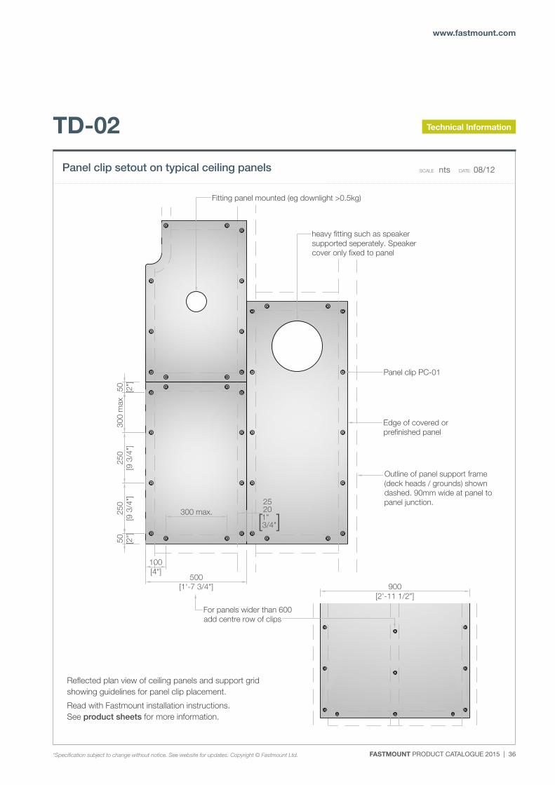
Fitting panel mounted (eg downlight >0.5kg)
heavy fitting such as speakersupported seperately. Speakercover only fixed to panel
Panel clip PC-01
Edge of covered orprefinished panel
Outline of panel support frame(deck heads / grounds) showndashed. 90mm wide at panel topanel junction.25
20 [1"
3/4"]
Reflected plan view of ceiling panels & supportgrid showing guidelines for panel clip placement.Read with Fastmount installation instructions.See product sheets for more information
TD-02Panel Clip setout on typical ceiling panels
nts 0613scale: date:
ref:
Subject to change without notice. see website for updateswww.fastmount.com Copyright ©Fastmount Limited
C:\L
ocal
Wor
kSpa
ce\P
roje
cts\
Pane
l mou
nt\f
astm
ount
cov
ered
pan
el in
stal
latio
n.dw
g, 2
0/06
/201
3 6:
20:1
6 p.
m.
TD-02
Reflected plan view of ceiling panels and support grid showing guidelines for panel clip placement.
Read with Fastmount installation instructions. See product sheets for more information.
Panel clip setout on typical ceiling panels SCALE nts DATE 08/12
*Specification subject to change without notice. See website for updates. Copyright © Fastmount Ltd.
Technical Information
37 | FASTMOUNT PRODUCT CATALOGUE 2015
FASTMOUNT Setting the standard for panel mounting
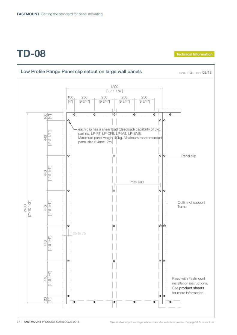
Panel clip
Outline of supportframe
Panel clip setout on large wall panelsLow Profile range (see TD-09 for Standard range)
nts
TD-08
06/13
Read with Fastmount installation instructions. Seeproduct sheets & drawing TD-02 for more information.
scale: date:
ref:
Subject to change without notice. see website for updateswww.fastmount.com Copyright ©Fastmount Limited
2400
[7'-
10 1
/2"]
1200[3'-11 1/4"]
100
[4"]
440
[1'-
5 1/
4"]
440
[1'-
5 1/
4"]
440
[1'-
5 1/
4"]
440
[1'-
5 1/
4"]
440
[1'-
5 1/
4"]
100
[4"]
100[4"]
250[9 3/4"]
250[9 3/4"]
250[9 3/4"]
250[9 3/4"]
25 to 75
max 600
each clip has a shear load (deadload) capability of 3kg.part no. LP-F8, LP-DF8, LP-M8, LP-SM8.Maximum panel weight 40kg. Maximum recommendedpanel size 2.4mx1.2m
C:\L
ocal
Wor
kSpa
ce\P
roje
cts\
Pane
l mou
nt\f
astm
ount
cov
ered
pan
el in
stal
latio
n.dw
g, 2
0/06
/201
3 6:
37:0
7 p.
m.
Read with Fastmount installation instructions. See product sheets for more information.
TD-08
Low Profile Range Panel clip setout on large wall panels SCALE nts DATE 08/12
Technical Information
*Specification subject to change without notice. See website for updates. Copyright © Fastmount Ltd.
FASTMOUNT PRODUCT CATALOGUE 2015 | 38
www.fastmount.com
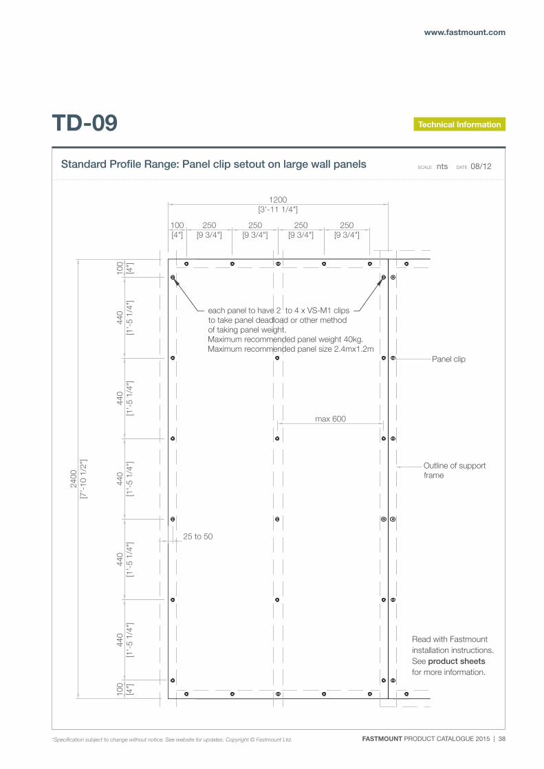
Panel clip
Outline of supportframe
Panel Clip setout on large wall panelsStandard range (see TD-08 for Low Profile)
nts
TD-09
06/13
Read with Fastmount installation instructions. Seeproduct sheets & drawing TD-02 for more information.
scale: date:
ref:
Subject to change without notice. see website for updateswww.fastmount.com Copyright ©Fastmount Limited
2400
[7'-
10 1
/2"]
1200[3'-11 1/4"]
100
[4"]
440
[1'-
5 1/
4"]
440
[1'-
5 1/
4"]
440
[1'-
5 1/
4"]
440
[1'-
5 1/
4"]
440
[1'-
5 1/
4"]
100
[4"]
100[4"]
250[9 3/4"]
250[9 3/4"]
250[9 3/4"]
250[9 3/4"]
25 to 50
max 600
each panel to have 2 to 4 x VS-M1 clipsto take panel deadload or other methodof taking panel weight.Maximum recommended panel weight 40kg.Maximum recommended panel size 2.4mx1.2m
C:\L
ocal
Wor
kSpa
ce\P
roje
cts\
Pane
l mou
nt\f
astm
ount
cov
ered
pan
el in
stal
latio
n.dw
g, 2
0/06
/201
3 6:
36:0
5 p.
m.
Read with Fastmount installation instructions. See product sheets for more information.
TD-09
Standard Profile Range: Panel clip setout on large wall panels SCALE nts DATE 08/12
Technical Information
*Specification subject to change without notice. See website for updates. Copyright © Fastmount Ltd.
39 | FASTMOUNT PRODUCT CATALOGUE 2015
FASTMOUNT Setting the standard for panel mounting
FASTMOUNT PRODUCT CATALOGUE 2015 | 40
www.fastmount.com
Installation Guides
Visit www.fastmount.com to view installation videos
41 | FASTMOUNT PRODUCT CATALOGUE 2015
FASTMOUNT Setting the standard for panel mounting
PC-M1A PC-M2H
PC-SM2HPC-SM2
CT-10CT-07CT-01 CT-03PC-VM1
P. +64 21 725 418 / F. +64 9 909 6034 / E. [email protected] / Designed & Manufactured in New Zealand www.fastmount.com
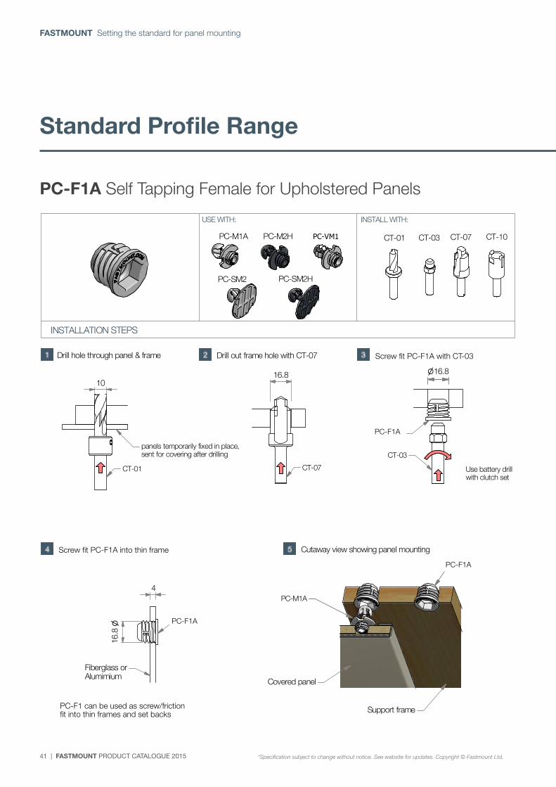
PC-F1A Self tapping female
*Specification subject to change without notice, see website for updates. Copyright © Fastmount Ltd.
INSTALLATION GUIDE PC-F1A / DATE 0314
INSTALLATION STEPS
USE WITH: INSTALL WITH:
CT-01
panels temporarily fixed in place, sent for covering after drilling
1016.8
CT-07
PC-F1
CT-03
Fiberglass orAlumimium
PC-F1
4
16.8
Support frame
Covered panel
Drill hole through panel & frame Drill out frame hole with CT-07 Screw fit PC-F1 with CT-03
16.8
Use battery drillwith clutch set
Screw fit PC-F1 into thin frame
PC-F1 can be used as screw / friction fitinto thin frames & seat backs
Cutaway view showing panel mounting
(see reverse for more options)
PC-M1A
PC-F1
(page 1 of 2)PC-F1A Self Tapping Female for Upholstered Panels
Screw fit PC-F1A with CT-03
Screw fit PC-F1A into thin frame
PC-F1 can be used as screw/friction fit into thin frames and set backs
PC-F1A
PC-F1A
PC-F1A
*Specification subject to change without notice. See website for updates. Copyright © Fastmount Ltd.
Standard Profile Range
FASTMOUNT PRODUCT CATALOGUE 2015 | 42
www.fastmount.com
Installation Guides
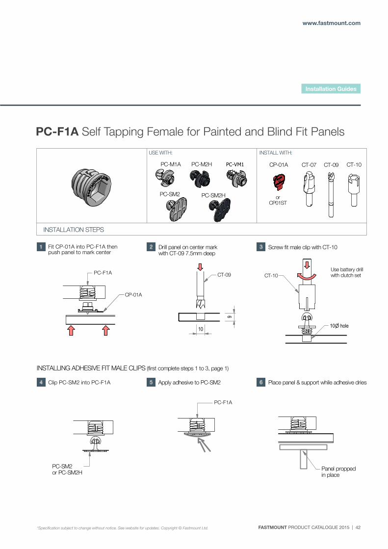
PC-F1A Self Tapping Female for Painted and Blind Fit Panels
PC-M1A
PC-SM2
PC-M2H
PC-SM2H
CP-01A CT-09 CT-10CT-07PC-VM1
P. +64 21 725 418 / F. +64 9 909 6034 / E. [email protected] / Designed & Manufactured in New Zealand www.fastmount.com
PC-F1A Self tapping female
*Specification subject to change without notice, see website for updates. Copyright © Fastmount Ltd.
INSTALLATION GUIDE PC-F1A / DATE 0314
INSTALLATION STEPS
USE WITH: INSTALL WITH:
Fit CP-01A into PC-F1then push panel to mark center
Drill panel on center markwith CT-09 7.5mm deep
Screw fit male clip with CT-10
(continued from previous page)
(page 2)
PC-F1 CT-09
10
9
CT-10
10 hole
Use battery drillwith clutch set
CP-01A
INSTALLING ADHESIVE FIT MALE CLIPS (first complete steps 1 to 3, page 1)
PC-SM2or PC-SM2H
PC-F1
Panel proppedin place
Clip PC-SM2 into PC-F1 Apply adhesive to PC-SM2 Place panel & support while adhesive dries
orCP01ST
Fit CP-01A into PC-F1A then push panel to mark center
Clip PC-SM2 into PC-F1A
PC-F1A
PC-F1A
*Specification subject to change without notice. See website for updates. Copyright © Fastmount Ltd.
43 | FASTMOUNT PRODUCT CATALOGUE 2015
FASTMOUNT Setting the standard for panel mounting
PC-M1A PC-M2H
PC-SM2HPC-SM2
PC-VM1
P. +64 21 725 418 / F. +64 9 909 6034 / E. [email protected] / Designed & Manufactured in New Zealand www.fastmount.com
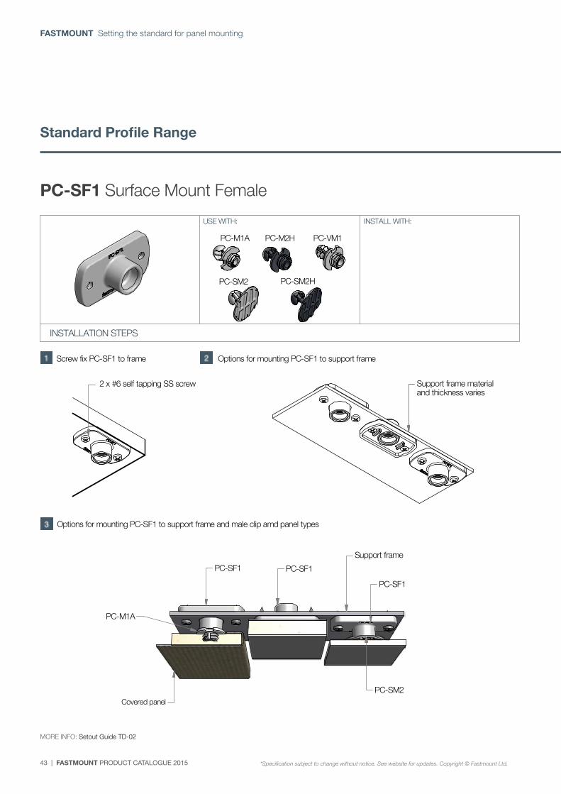
PC-SF1 Surface mount female
*Specification subject to change without notice, see website for updates. Copyright © Fastmount Ltd.
INSTALLATION GUIDE PC-SF1 / DATE 0314
INSTALLATION STEPS
USE WITH: INSTALL WITH:
Screw fix PC-SF1 to frame Options for mounting PC-SF1 to support frame
(see reverse for more options)
(page 1 of 2)
2 x #6 self tapping SS screw
PC-M1A
Covered panel
PC-SM2
PC-SF1
Support frame
PC-SF1
PC-SF1
Support frame materialand thickness varies
Options for mounting PC-SF1 to support frame and male clip amd panel types
MORE INFO: Setout Guide TD-02
PC-SF1 Surface Mount Female
MORE INFO: Setout Guide TD-02
PC-M1A PC-M2H
PC-SM2HPC-SM2
PC-VM1
P. +64 21 725 418 / F. +64 9 909 6034 / E. [email protected] / Designed & Manufactured in New Zealand www.fastmount.com
PC-SF1 Surface mount female
*Specification subject to change without notice, see website for updates. Copyright © Fastmount Ltd.
INSTALLATION GUIDE PC-SF1 / DATE 0314
INSTALLATION STEPS
USE WITH: INSTALL WITH:
Screw fix PC-SF1 to frame Options for mounting PC-SF1 to support frame
(see reverse for more options)
(page 1 of 2)
2 x #6 self tapping SS screw
PC-M1A
Covered panel
PC-SM2
PC-SF1
Support frame
PC-SF1
PC-SF1
Support frame materialand thickness varies
Options for mounting PC-SF1 to support frame and male clip amd panel types
MORE INFO: Setout Guide TD-02
*Specification subject to change without notice. See website for updates. Copyright © Fastmount Ltd.
Standard Profile Range
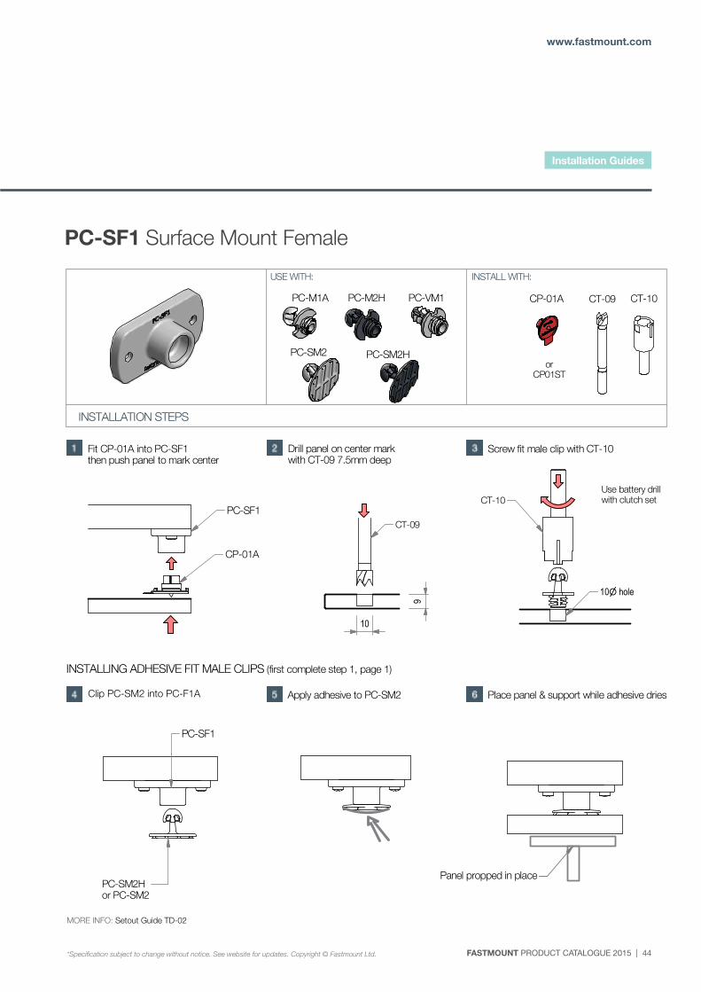
FASTMOUNT PRODUCT CATALOGUE 2015 | 44
www.fastmount.com
PC-M1A
PC-SM2
PC-M2H
PC-SM2H
CP-01A CT-09 CT-10PC-VM1
P. +64 21 725 418 / F. +64 9 909 6034 / E. [email protected] / Designed & Manufactured in New Zealand www.fastmount.com
PC-SF1 Surface mount female
*Specification subject to change without notice, see website for updates. Copyright © Fastmount Ltd.
INSTALLATION GUIDE PC-SF1 / DATE 0314
INSTALLATION STEPS
USE WITH: INSTALL WITH:
Fit CP-01A into PC-SF1then push panel to mark center
Drill panel on center markwith CT-09 7.5mm deep
Screw fit male clip with CT-10
(continued from previous page)
(page 2)
CT-09
10
9
CT-10
10 hole
Use battery drillwith clutch set
INSTALLING ADHESIVE FIT MALE CLIPS (first complete step 1, page 1)
Clip PC-SM2 into PC-F1 Apply adhesive to PC-SM2 Place panel & support while adhesive dries
CP-01A
PC-SF1
PC-SM2Hor PC-SM2
PC-SF1
Panel propped in place
MORE INFO: Setout Guide TD-02
orCP01ST
PC-SF1 Surface Mount Female
MORE INFO: Setout Guide TD-02
Clip PC-SM2 into PC-F1A
Installation Guides
*Specification subject to change without notice. See website for updates. Copyright © Fastmount Ltd.
45 | FASTMOUNT PRODUCT CATALOGUE 2015
FASTMOUNT Setting the standard for panel mounting
PC-M1A
PC-SM2
PC-M2H
PC-SM2H
CP-01A CT-09 CT-10PC-VM1
P. +64 21 725 418 / F. +64 9 909 6034 / E. [email protected] / Designed & Manufactured in New Zealand www.fastmount.com
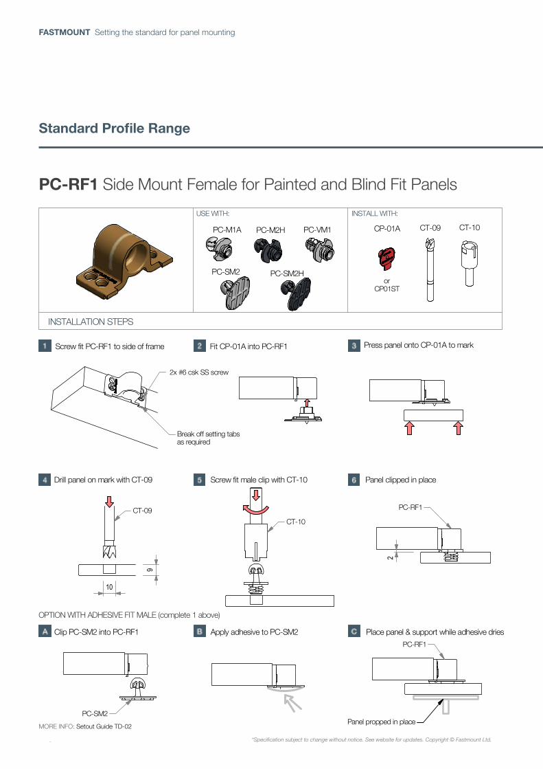
PC-RF1 Side mount female
*Specification subject to change without notice, see website for updates. Copyright © Fastmount Ltd.
INSTALLATION GUIDE PC-RF1 / DATE 0314
INSTALLATION STEPS
USE WITH: INSTALL WITH:
2x #6 csk SS screw
Break off setting tabsas required
Screw fit PC-RF1 to side of frame Fit CP-01A into PC-RF1 Press panel onto CP-01A to mark
CT-09
10
9
CT-10
PC-RF1
2
PC-SM2
PC-RF1
Drill panel on mark with CT-09 Screw fit male clip with CT-10 Panel clipped in place
OPTION WITH ADHESIVE FIT MALE (complete 1 above)
Clip PC-SM2 into PC-RF1 Apply adhesive to PC-SM2 Place panel & support while adhesive dries
Panel propped in placeMORE INFO: Setout Guide TD-02
orCP01ST
PC-RF1 Side Mount Female for Painted and Blind Fit Panels
MORE INFO: Setout Guide TD-02
*Specification subject to change without notice. See website for updates. Copyright © Fastmount Ltd.
Standard Profile Range
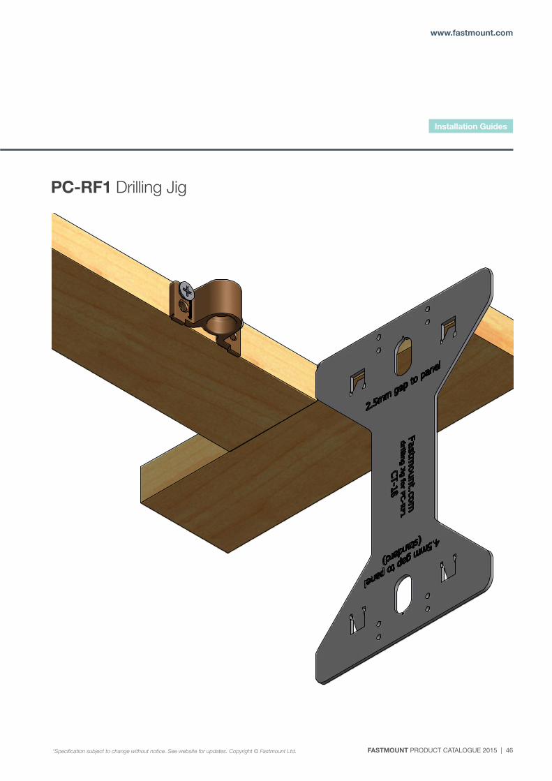
FASTMOUNT PRODUCT CATALOGUE 2015 | 46
www.fastmount.com
RF1 drilling jig at deck head ( 1 : 1 )
Drilling Jig PC-RF1
CT-18Fastmount Ltd
Ron Hanley 9/07/2010
1
Designed by Checked by Approved by Date
1 / 2 Edition Sheet
Date
PC-RF1 Drilling Jig
Installation Guides
*Specification subject to change without notice. See website for updates. Copyright © Fastmount Ltd.
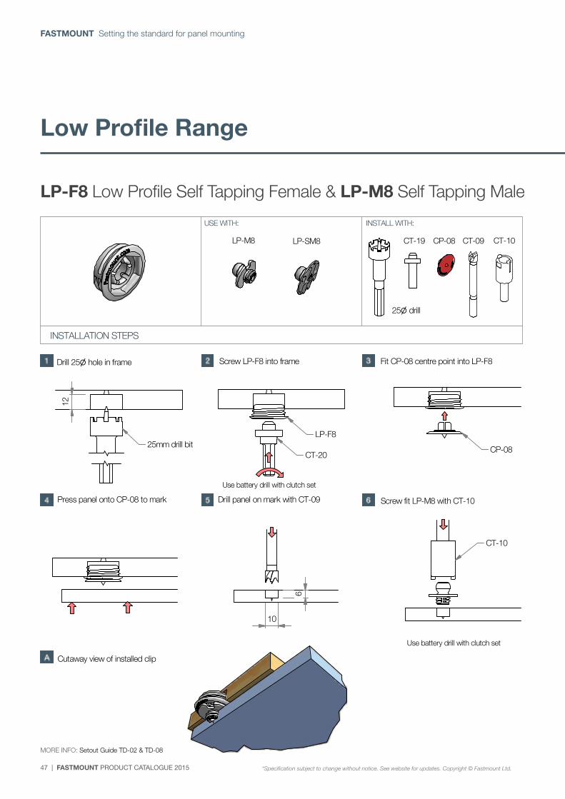
47 | FASTMOUNT PRODUCT CATALOGUE 2015
FASTMOUNT Setting the standard for panel mounting
CT-10LP-M8 LP-SM8 CP-08 CT-09CT-19
A ( 1 : 2 )
A
P. +64 21 725 418 / F. +64 9 909 6034 / E. [email protected] / Designed & Manufactured in New Zealand www.fastmount.com
LP-F8 Low Profile self tapping female
*Specification subject to change without notice, see website for updates. Copyright © Fastmount Ltd.
INSTALLATION GUIDE LP-F8 / DATE 1214
INSTALLATION STEPS
USE WITH: INSTALL WITH:
Drill 25 hole in frame Screw LP-F8 into frame Fit CP-08 centre point into LP-F8
Use battery drill with clutch set
Press panel onto CP-08 to mark Drill panel on mark with CT-09
(see reverse for more options)
25 drill
12
CT-2025mm drill bit
LP-F8
CP-08
6
10
Screw fit LP-M8 with CT-10
Use battery drill with clutch set
CT-10
Cutaway view of installed clip
MORE INFO: Setout Guide TD-02 & TD-08
(page 1 of 2)LP-F8 Low Profile Self Tapping Female & LP-M8 Self Tapping Male
MORE INFO: Setout Guide TD-02 & TD-08
Low Profile Range
*Specification subject to change without notice. See website for updates. Copyright © Fastmount Ltd.
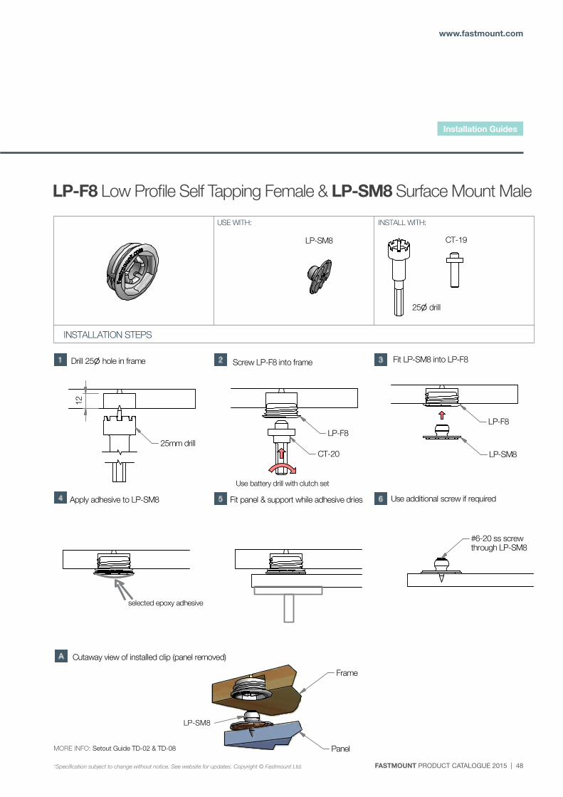
FASTMOUNT PRODUCT CATALOGUE 2015 | 48
www.fastmount.com
LP-SM8 CT-19
B ( 1 : 2 )
B
P. +64 21 725 418 / F. +64 9 909 6034 / E. [email protected] / Designed & Manufactured in New Zealand www.fastmount.com
LP-F8 Low Profile self tapping female
*Specification subject to change without notice, see website for updates. Copyright © Fastmount Ltd.
INSTALLATION GUIDE LP-F8 / DATE 1214
INSTALLATION STEPS
USE WITH: INSTALL WITH:
(continued from previous page; GLUE ON OPTION)
Apply adhesive to LP-SM8 Fit panel & support while adhesive dries
25 drill
25mm drill
12
LP-F8
CT-20
Use battery drill with clutch set
Screw LP-F8 into frameDrill 25 hole in frame Fit LP-SM8 into LP-F8
LP-F8
LP-SM8
#6-20 ss screwthrough LP-SM8
Use additional screw if required
selected epoxy adhesive
Cutaway view of installed clip (panel removed)
LP-SM8
Panel
Frame
MORE INFO: Setout Guide TD-02 & TD-08
(page 2 of 2)LP-F8 Low Profile Self Tapping Female & LP-SM8 Surface Mount Male
MORE INFO: Setout Guide TD-02 & TD-08
LP-SM8
Installation Guides
*Specification subject to change without notice. See website for updates. Copyright © Fastmount Ltd.
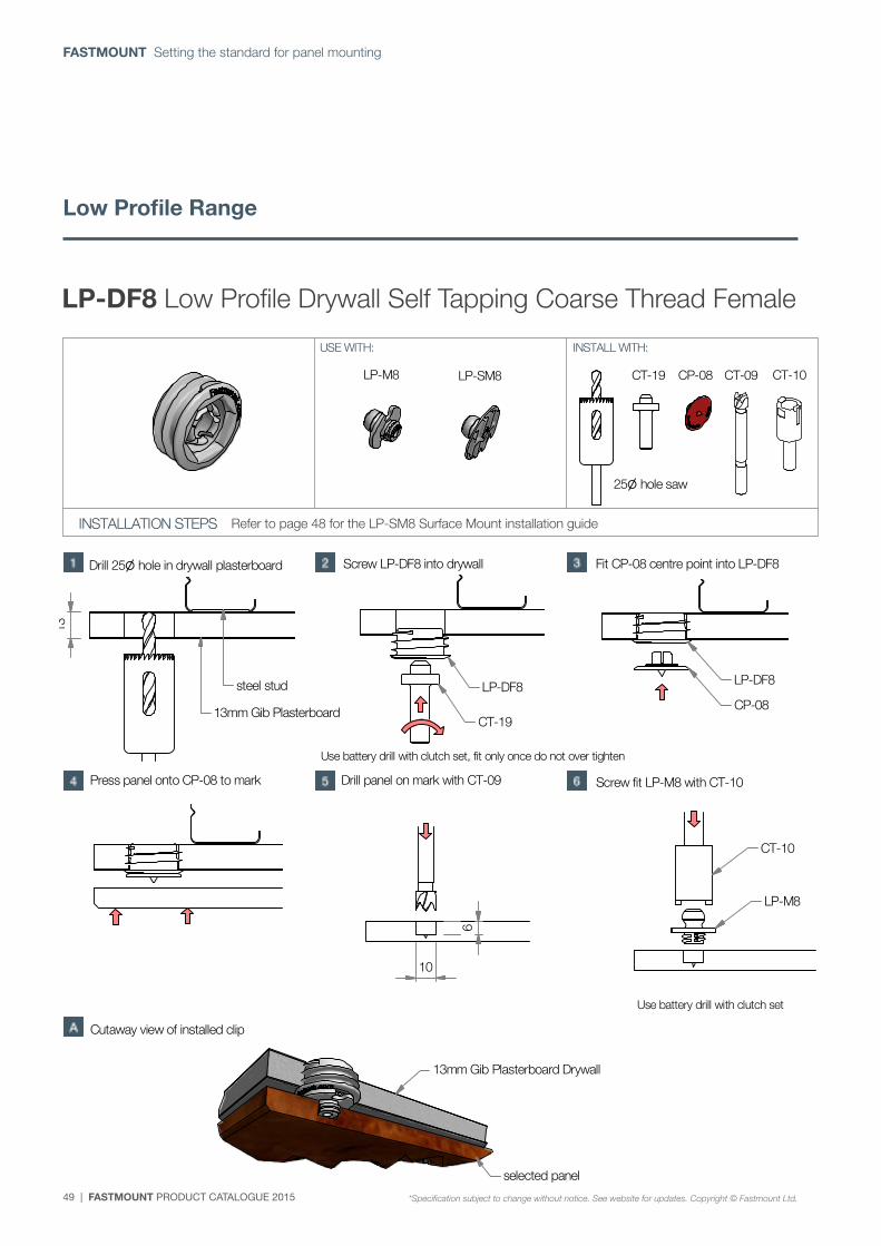
49 | FASTMOUNT PRODUCT CATALOGUE 2015
FASTMOUNT Setting the standard for panel mounting
CT-10LP-M8 LP-SM8 CP-08 CT-09CT-19
D ( 1 :3 )
D
P. +64 21 725 418 / F. +64 9 909 6034 / E. [email protected] / Designed & Manufactured in New Zealand www.fastmount.com
LP-DF8 Low Profile Drywall self tapping coarse thread female
*Specification subject to change without notice, see website for updates. Copyright © Fastmount Ltd.
INSTALLATION GUIDE LP-DF8 / DATE 0812
INSTALLATION STEPS
USE WITH: INSTALL WITH:
Drill 25 hole in drywall plasterboard Screw LP-DF8 into drywall Fit CP-08 centre point into LP-DF8
Use battery drill with clutch set, fit only once do not over tighten
Press panel onto CP-08 to mark Drill panel on mark with CT-09
(see reverse for more options)
25 hole saw6
10
Screw fit LP-M8 with CT-10
Use battery drill with clutch set
CT-10
Cutaway view of installed clip
13
13mm Gib Plasterboard
LP-DF8
CT-19
LP-DF8
CP-08
LP-M8
13mm Gib Plasterboard Drywall
selected panel
steel stud
LP-DF8 Low Profile Drywall Self Tapping Coarse Thread Female
Refer to page 48 for the LP-SM8 Surface Mount installation guide
*Specification subject to change without notice. See website for updates. Copyright © Fastmount Ltd.
Low Profile Range
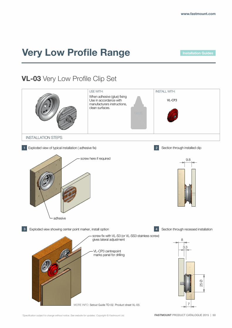
FASTMOUNT PRODUCT CATALOGUE 2015 | 50
www.fastmount.com
VL-CP3
P. +64 21 725 418 / F. +64 9 909 6034 / E. [email protected] / Designed & Manufactured in New Zealand www.fastmount.com
VL-03 Very Low Profile clip set
*Specification subject to change without notice, see website for updates. Copyright © Fastmount Ltd.
INSTALLATION GUIDE VL-03 / DATE 0113
INSTALLATION STEPS
USE WITH: INSTALL WITH:
GLUE
Exploded view of typical installation ( adhesive fix)
#6g ss wafer headtek screw (or similiar)
Section through installed clip
Section through recessed installationExploded view showing center point marker, install option
When adhesive (glue) fixingUse in accordance withmanufacturers instructions,clean surfaces.
9.8
8
3.3
7
VL-CP3 centrepoint marks panel for drilling
screw here if required
adhesive
screw fix with VL-S3 (or VL-SS3 stainless screw)gives lateral adjustment
MORE INFO: Setout Guide TD-02 Product sheet VL-03
25 Ø
VL-03 Very Low Profile Clip Set
MORE INFO: Setout Guide TD-02. Product sheet VL-03.
Installation Guides
*Specification subject to change without notice. See website for updates. Copyright © Fastmount Ltd.
Very Low Profile Range
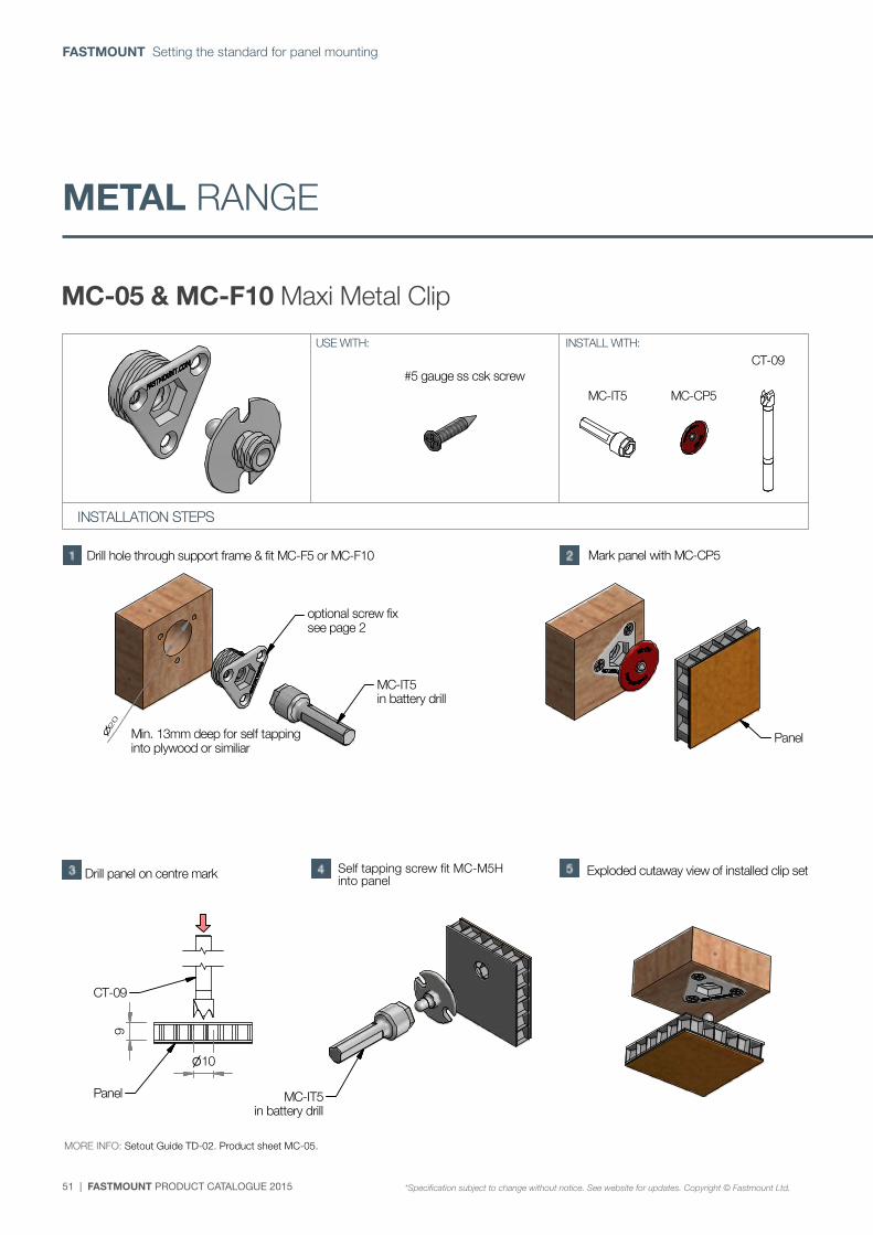
51 | FASTMOUNT PRODUCT CATALOGUE 2015
FASTMOUNT Setting the standard for panel mounting
MC-05 & MC-F10 Maxi Metal Clip
MC-IT5 MC-CP5
CT-09
P. +64 21 725 418 / F. +64 9 909 6034 / E. [email protected] / Designed & Manufactured in New Zealand www.fastmount.com
MC-05 & MC-10 Maxi Metal Clip Set
*Specification subject to change without notice, see website for updates. Copyright © Fastmount Ltd.
INSTALLATION GUIDE MC-05 & MC-10 / DATE 1214
INSTALLATION STEPS
USE WITH: INSTALL WITH:
Drill hole through support frame & fit MC-F5 or MC-F10
#5 gauge ss csk screw
Mark panel with MC-CP5
Self tapping screw fit MC-M5 into panelDrill panel on centre mark
MORE INFO: Setout Guide TD-02 Product sheet MC-05
Min. 13mm deep for self tappinginto plywood or similiar
20
MC-IT5in battery drill
Panel
CT-09
Exploded cutaway view of installed clip set
10
9
MC-IT5in battery drill
optional screw fixsee page 2
Panel
(page 1 of 2)
METAL RANGE
MORE INFO: Setout Guide TD-02. Product sheet MC-05.
Self tapping screw fit MC-M5H into panel
*Specification subject to change without notice. See website for updates. Copyright © Fastmount Ltd.
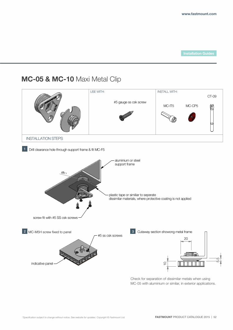
FASTMOUNT PRODUCT CATALOGUE 2015 | 52
www.fastmount.com
MC-05 & MC-10 Maxi Metal Clip
MC-IT5 MC-CP5
CT-09
P. +64 21 725 418 / F. +64 9 909 6034 / E. [email protected] / Designed & Manufactured in New Zealand www.fastmount.com
MC-05 Maxi Metal Clip Set
*Specification subject to change without notice, see website for updates. Copyright © Fastmount Ltd.
INSTALLATION GUIDE MC-05 / DATE 1113
INSTALLATION STEPS
USE WITH: INSTALL WITH:
#5 gauge ss csk screw
Drill clearance hole through support frame & fit MC-F5
MC-M5 screw fixed to panel#5 ss csk screws
indicative panel
5.5
10
Cutaway section showong metal frame
(page 2 of 2)
20
aluminium or steel support frame
screw fit with #5 SS csk screws
21
plastic tape or similiar to seperatedissimliar materials, where protective coating is not applied
check for seperation of dissimliar metals when usingMC-05 with aluminium or simliar, in exterior applications
MC-IT5 MC-CP5
CT-09
P. +64 21 725 418 / F. +64 9 909 6034 / E. [email protected] / Designed & Manufactured in New Zealand www.fastmount.com
MC-05 Maxi Metal Clip Set
*Specification subject to change without notice, see website for updates. Copyright © Fastmount Ltd.
INSTALLATION GUIDE MC-05 / DATE 1113
INSTALLATION STEPS
USE WITH: INSTALL WITH:
#5 gauge ss csk screw
Drill clearance hole through support frame & fit MC-F5
MC-M5 screw fixed to panel#5 ss csk screws
indicative panel5.
5
10
Cutaway section showong metal frame
(page 2 of 2)
20
aluminium or steel support frame
screw fit with #5 SS csk screws
21
plastic tape or similiar to seperatedissimliar materials, where protective coating is not applied
check for seperation of dissimliar metals when usingMC-05 with aluminium or simliar, in exterior applications
Check for separation of dissimilar metals when using MC-05 with aluminium or similar, in exterior applications.
MC-M5H screw fixed to panel
Installation Guides
*Specification subject to change without notice. See website for updates. Copyright © Fastmount Ltd.
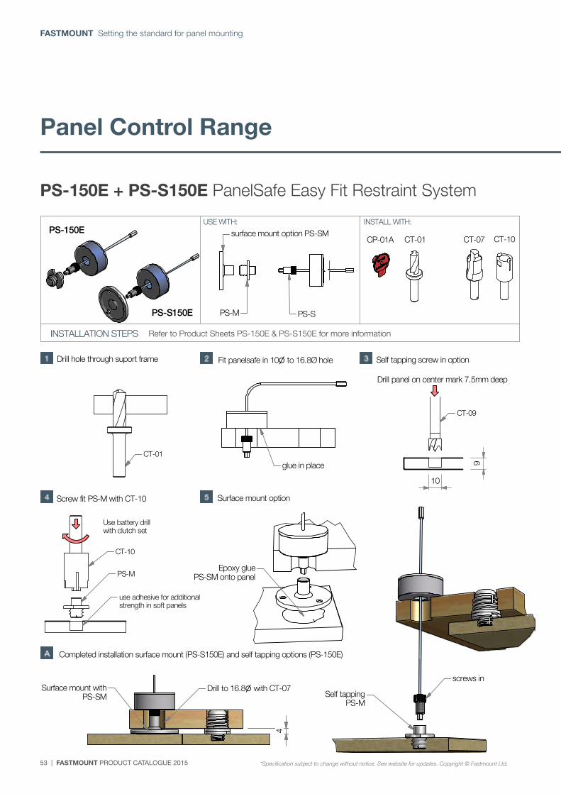
53 | FASTMOUNT PRODUCT CATALOGUE 2015
FASTMOUNT Setting the standard for panel mounting
CT-10CT-07CT-01CP-01A
B
C
P. +64 21 725 418 / F. +64 9 909 6034 / E. [email protected] / Designed & Manufactured in New Zealand www.fastmount.com
PS-150E + PS-S150E PanelSafe Easy fit restraint system
*Specification subject to change without notice, see website for updates. Copyright © Fastmount Ltd.
INSTALLATION GUIDE PS-150E + PS-S150E / DATE 0312
INSTALLATION STEPS
USE WITH: INSTALL WITH:
Drill hole through suport frame Fit panelsafe in 10 to 16.8Ø hole
Surface mount option
Use battery drillwith clutch set
(see reverse for more details) Refer to product sheets PS-150E & PSS150E for more information
(page 1of 2)
910
Self tapping screw in option
Screw fit PS-M with CT-10
CT-01
CT-09
CT-10
PS-M
use adhesive for additionalstrength in soft panels
Completed installation surface mount (PS-S150E) and self tapping options (PS-150E)
surface mount option PS-SM
PS-M PS-S
glue in place
Drill panel on center mark 7.5mm deep
Epoxy gluePS-SM onto panel
Surface mount withPS-SM Self tapping
PS-M
screws in
PS-150E
PS-S150E
Drill to 16.8 with CT-07
4
PS-150E + PS-S150E PanelSafe Easy Fit Restraint System
Refer to Product Sheets PS-150E & PS-S150E for more information
*Specification subject to change without notice. See website for updates. Copyright © Fastmount Ltd.
Panel Control Range
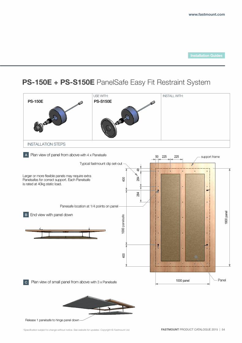
FASTMOUNT PRODUCT CATALOGUE 2015 | 54
www.fastmount.com
P. +64 21 725 418 / F. +64 9 909 6034 / E. [email protected] / Designed & Manufactured in New Zealand www.fastmount.com
PS-150E + PS-S150E PanelSafe Easy fit restraint system
*Specification subject to change without notice, see website for updates. Copyright © Fastmount Ltd.
INSTALLATION GUIDE PS-150E + PS-S150E / DATE 0312
INSTALLATION STEPS
USE WITH: INSTALL WITH:
(continued from previous page)
(page 2)
Panel
support frame
Panesafe location at 1/4 points on panel
1000 panel
1800
pane
l
22522550
400
1000
pan
elsa
fe40
0
4828
428
4
Typical fastmount clip set-out
Larger or more flexible panels may require extra Panelsafes for correct support. Each Panelsafe is rated at 40kg static load.
Plan view of small panel from above with 3 x Panelsafe
Plan view of panel from above with 4 x Panelsafe
End view with panel down
Release 1 panelsafe to hinge panel down
PS-S150EPS-150E
PS-150E + PS-S150E PanelSafe Easy Fit Restraint System
Installation Guides
*Specification subject to change without notice. See website for updates. Copyright © Fastmount Ltd.
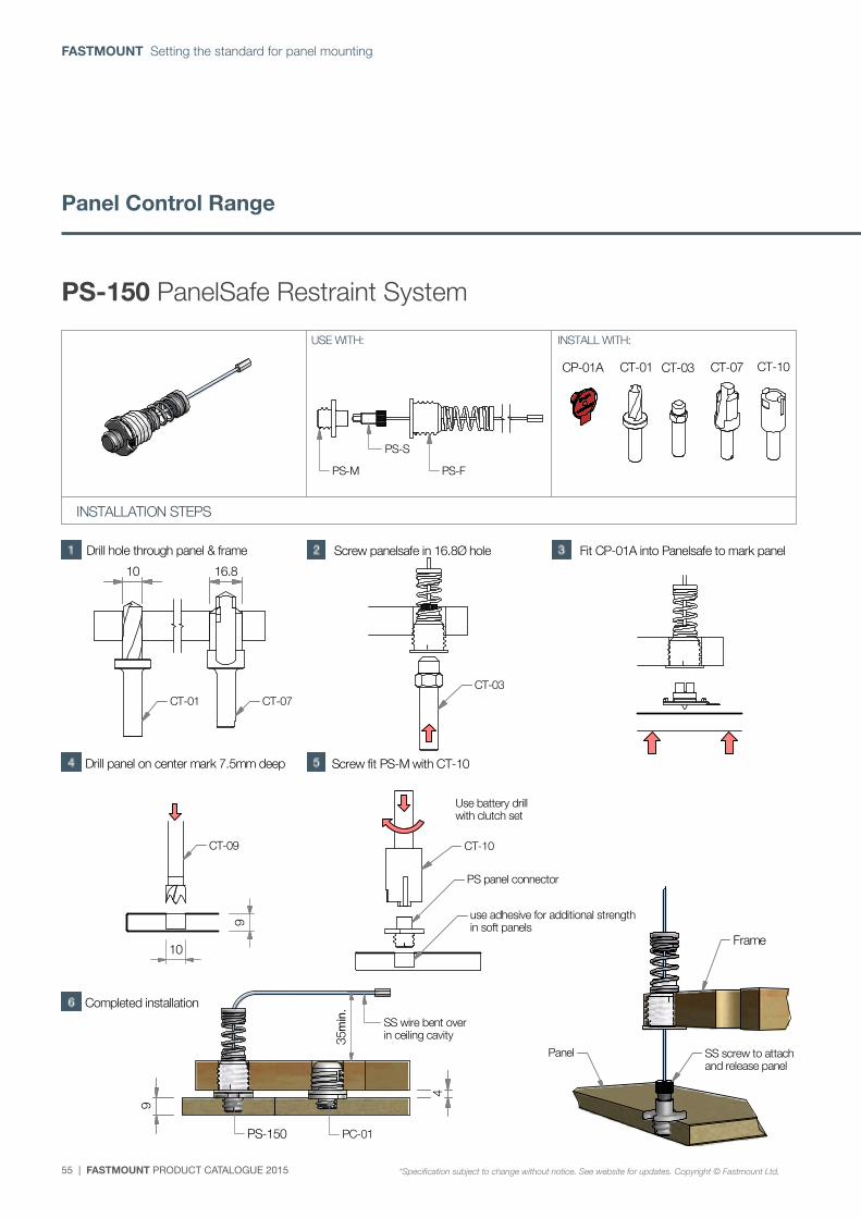
55 | FASTMOUNT PRODUCT CATALOGUE 2015
FASTMOUNT Setting the standard for panel mounting
CT-10CT-07CT-01 CT-03CP-01A
A ( 1 : 2 )
A
P. +64 21 725 418 / F. +64 9 909 6034 / E. [email protected] / Designed & Manufactured in New Zealand www.fastmount.com
PS-150 PanelSafe restraint system
*Specification subject to change without notice, see website for updates. Copyright © Fastmount Ltd.
INSTALLATION GUIDE PS-150 / DATE 0911
INSTALLATION STEPS
USE WITH: INSTALL WITH:
Drill hole through panel & frame Screw panelsafe in 16.8Ø hole Fit CP-01A into Panelsafe to mark panel
Use battery drillwith clutch set
(see reverse for more details)
(page 1of 2)
9
10
Drill panel on center mark 7.5mm deep Screw fit PS-M with CT-10
SS wire bent overin ceiling cavity
PS-150
35min.
PS-FPS-M
PS-S
16.810
CT-01 CT-07CT-03
9
4
PC-01
CT-09 CT-10
PS panel connector
use adhesive for additional strengthin soft panels
Completed installation
SS screw to attachand release panel
Panel
Frame
PS-150 PanelSafe Restraint System
CT-10CT-07CT-01 CT-03CP-01A
A ( 1 : 2 )
A
P. +64 21 725 418 / F. +64 9 909 6034 / E. [email protected] / Designed & Manufactured in New Zealand www.fastmount.com
PS-150 PanelSafe restraint system
*Specification subject to change without notice, see website for updates. Copyright © Fastmount Ltd.
INSTALLATION GUIDE PS-150 / DATE 0911
INSTALLATION STEPS
USE WITH: INSTALL WITH:
Drill hole through panel & frame Screw panelsafe in 16.8Ø hole Fit CP-01A into Panelsafe to mark panel
Use battery drillwith clutch set
(see reverse for more details)
(page 1of 2)
9
10
Drill panel on center mark 7.5mm deep Screw fit PS-M with CT-10
SS wire bent overin ceiling cavity
PS-150
35min.
PS-FPS-M
PS-S
16.810
CT-01 CT-07CT-03
9
4
PC-01
CT-09 CT-10
PS panel connector
use adhesive for additional strengthin soft panels
Completed installation
SS screw to attachand release panel
Panel
Frame
Panel Control Range
*Specification subject to change without notice. See website for updates. Copyright © Fastmount Ltd.
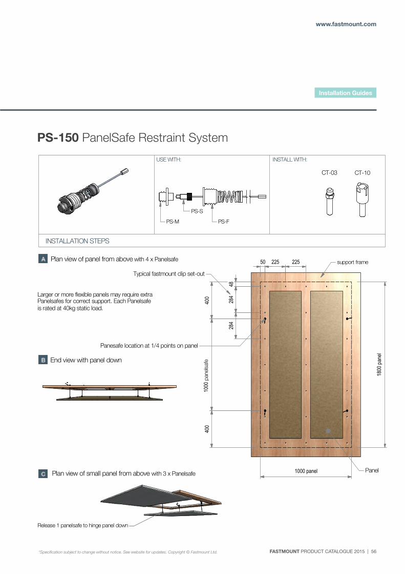
FASTMOUNT PRODUCT CATALOGUE 2015 | 56
www.fastmount.com
CT-03 CT-10
P. +64 21 725 418 / F. +64 9 909 6034 / E. [email protected] / Designed & Manufactured in New Zealand www.fastmount.com
PS-150 PanelSafe restraint system
*Specification subject to change without notice, see website for updates. Copyright © Fastmount Ltd.
INSTALLATION GUIDE PS-150 / DATE 0911
INSTALLATION STEPS
USE WITH: INSTALL WITH:
(continued from previous page)
(page 2)
Panel
support frame
Panesafe location at 1/4 points on panel
1000 panel
1800
pan
el
22522550
400
1000
pan
elsa
fe40
0
4828
428
4
Typical fastmount clip set-out
Larger or more flexible panels may require extra Panelsafes for correct support. Each Panelsafe is rated at 40kg static load.
Plan view of small panel from above with 3 x Panelsafe
Plan view of panel from above with 4 x Panelsafe
PS-FPS-M
PS-S
End view with panel down
Release 1 panelsafe to hinge panel down
PS-150 PanelSafe Restraint System
CT-03 CT-10
P. +64 21 725 418 / F. +64 9 909 6034 / E. [email protected] / Designed & Manufactured in New Zealand www.fastmount.com
PS-150 PanelSafe restraint system
*Specification subject to change without notice, see website for updates. Copyright © Fastmount Ltd.
INSTALLATION GUIDE PS-150 / DATE 0911
INSTALLATION STEPS
USE WITH: INSTALL WITH:
(continued from previous page)
(page 2)
Panel
support frame
Panesafe location at 1/4 points on panel
1000 panel
1800
pan
el
22522550
400
1000
pan
elsa
fe40
0
4828
428
4
Typical fastmount clip set-out
Larger or more flexible panels may require extra Panelsafes for correct support. Each Panelsafe is rated at 40kg static load.
Plan view of small panel from above with 3 x Panelsafe
Plan view of panel from above with 4 x Panelsafe
PS-FPS-M
PS-S
End view with panel down
Release 1 panelsafe to hinge panel down
Installation Guides
*Specification subject to change without notice. See website for updates. Copyright © Fastmount Ltd.

P. +64 21 725 418 F. +64 9 909 6034 E. [email protected]
www.fastmount.com
DESIGNED & MANUFACTURED IN NEW ZEALAND
Visit www.fastmount.com to find your nearest distributor or request a trial kit online.
TM
Recommended