Design of Segmental Tunnel Linings for Serviceability Limit State
Mehdi Bakhshi, PhD, PE ACI Committee 544 & AECOM, New York
April, 2015
AASHTO SCOBS T-20: Technical Committee for Tunnels
• Introduction on FRC Segments
• Summary of ACI Guideline for FRC Segments
• Design Example for Mid-Size Tunnels
• Design for Serviceability Limit States
• Current and Future Research Studies
• Conclusion
Outline
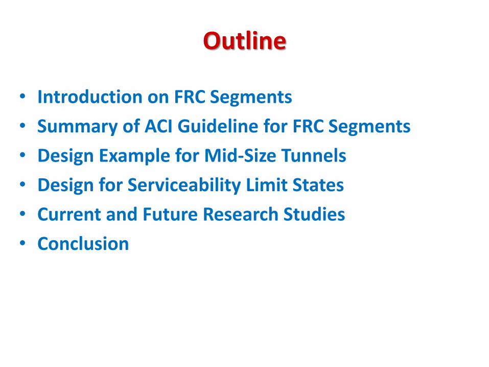
Introduction on FRC Segments
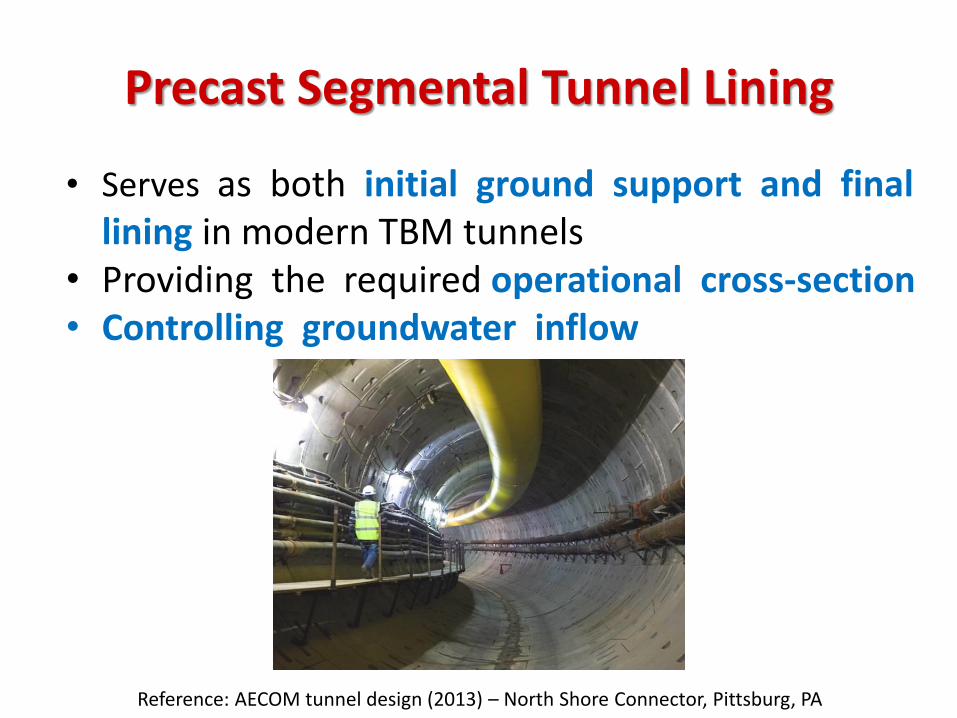
Precast Segmental Tunnel Lining
• Serves as both initial ground support and final lining in modern TBM tunnels
• Providing the required operational cross-section • Controlling groundwater inflow
Reference: AECOM tunnel design (2013) – North Shore Connector, Pittsburg, PA
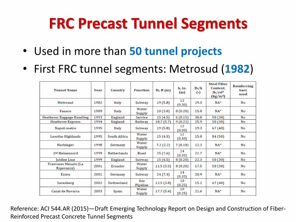
• Used in more than 50 tunnel projects
• First FRC tunnel segments: Metrosud (1982)
FRC Precast Tunnel Segments
Reference: ACI 544.AR (2015)—Draft Emerging Technology Report on Design and Construction of Fiber-Reinforced Precast Concrete Tunnel Segments
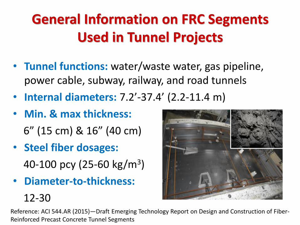
• Tunnel functions: water/waste water, gas pipeline, power cable, subway, railway, and road tunnels
• Internal diameters: 7.2’-37.4’ (2.2-11.4 m)
• Min. & max thickness:
6” (15 cm) & 16” (40 cm)
• Steel fiber dosages:
40-100 pcy (25-60 kg/m3)
• Diameter-to-thickness:
12-30
General Information on FRC Segments Used in Tunnel Projects
Reference: ACI 544.AR (2015)—Draft Emerging Technology Report on Design and Construction of Fiber-Reinforced Precast Concrete Tunnel Segments
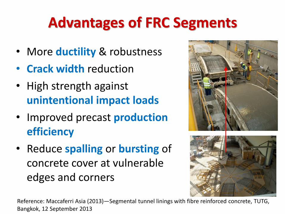
• More ductility & robustness
• Crack width reduction
• High strength against unintentional impact loads
• Improved precast production efficiency
• Reduce spalling or bursting of concrete cover at vulnerable edges and corners
Advantages of FRC Segments
Reference: Maccaferri Asia (2013)—Segmental tunnel linings with fibre reinforced concrete, TUTG, Bangkok, 12 September 2013
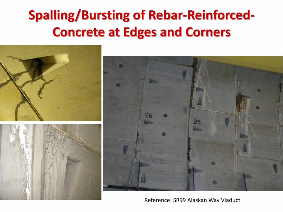
Spalling/Bursting of Rebar-Reinforced-Concrete at Edges and Corners
Reference: SR99 Alaskan Way Viaduct
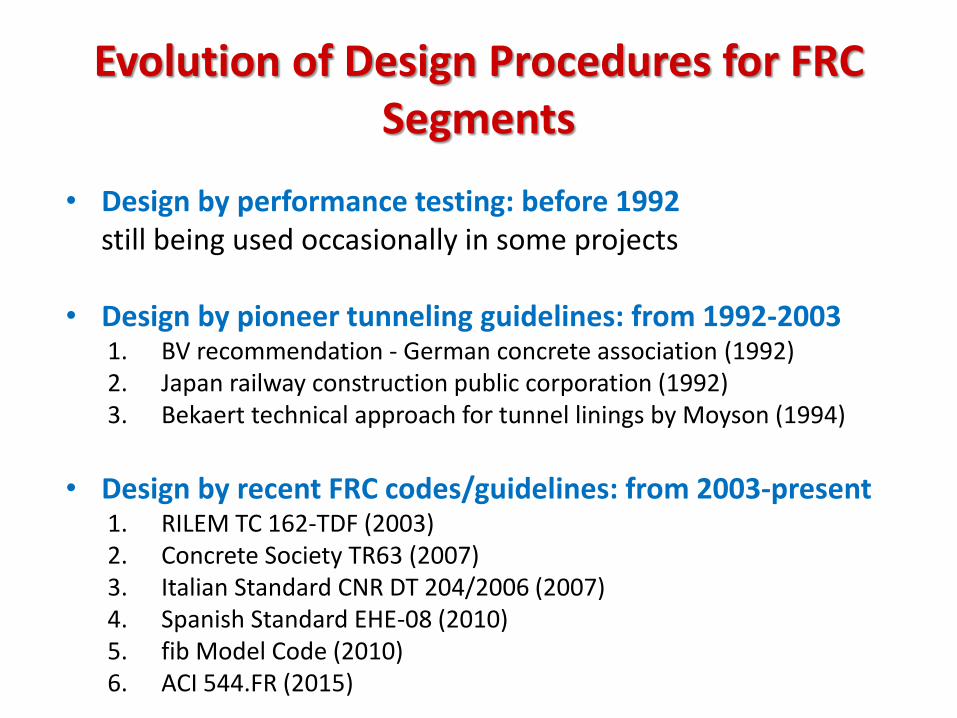
• Design by performance testing: before 1992 still being used occasionally in some projects • Design by pioneer tunneling guidelines: from 1992-2003
1. BV recommendation - German concrete association (1992) 2. Japan railway construction public corporation (1992) 3. Bekaert technical approach for tunnel linings by Moyson (1994)
• Design by recent FRC codes/guidelines: from 2003-present
1. RILEM TC 162-TDF (2003) 2. Concrete Society TR63 (2007) 3. Italian Standard CNR DT 204/2006 (2007) 4. Spanish Standard EHE-08 (2010) 5. fib Model Code (2010) 6. ACI 544.FR (2015)
Evolution of Design Procedures for FRC Segments
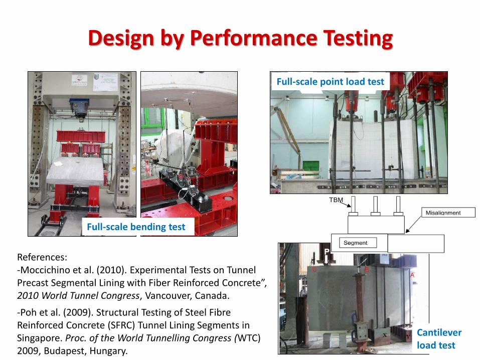
Design by Performance Testing
Full-scale bending test
Full-scale point load test
Misalignment
TBM
Cantilever load test
References: -Moccichino et al. (2010). Experimental Tests on Tunnel Precast Segmental Lining with Fiber Reinforced Concrete”, 2010 World Tunnel Congress, Vancouver, Canada.
-Poh et al. (2009). Structural Testing of Steel Fibre Reinforced Concrete (SFRC) Tunnel Lining Segments in Singapore. Proc. of the World Tunnelling Congress (WTC) 2009, Budapest, Hungary.
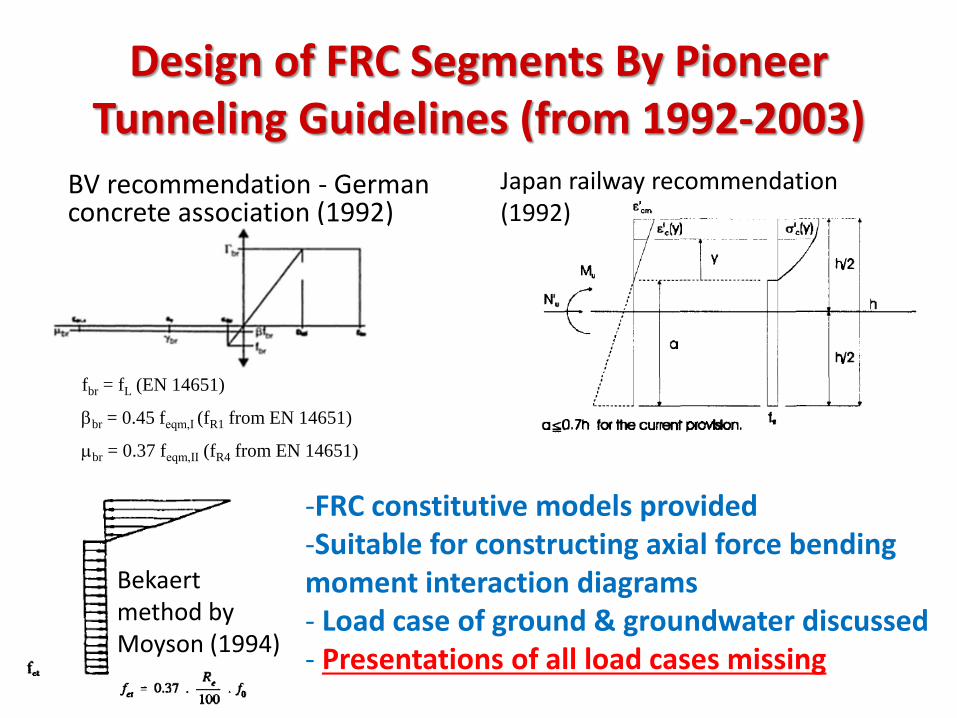
Design of FRC Segments By Pioneer Tunneling Guidelines (from 1992-2003)
BV recommendation - German concrete association (1992)
fbr = fL (EN 14651)
bbr = 0.45 feqm,Ι (fR1 from EN 14651)
mbr = 0.37 feqm,ΙΙ (fR4 from EN 14651)
Japan railway recommendation (1992)
-FRC constitutive models provided -Suitable for constructing axial force bending moment interaction diagrams - Load case of ground & groundwater discussed - Presentations of all load cases missing
Bekaert method by Moyson (1994)
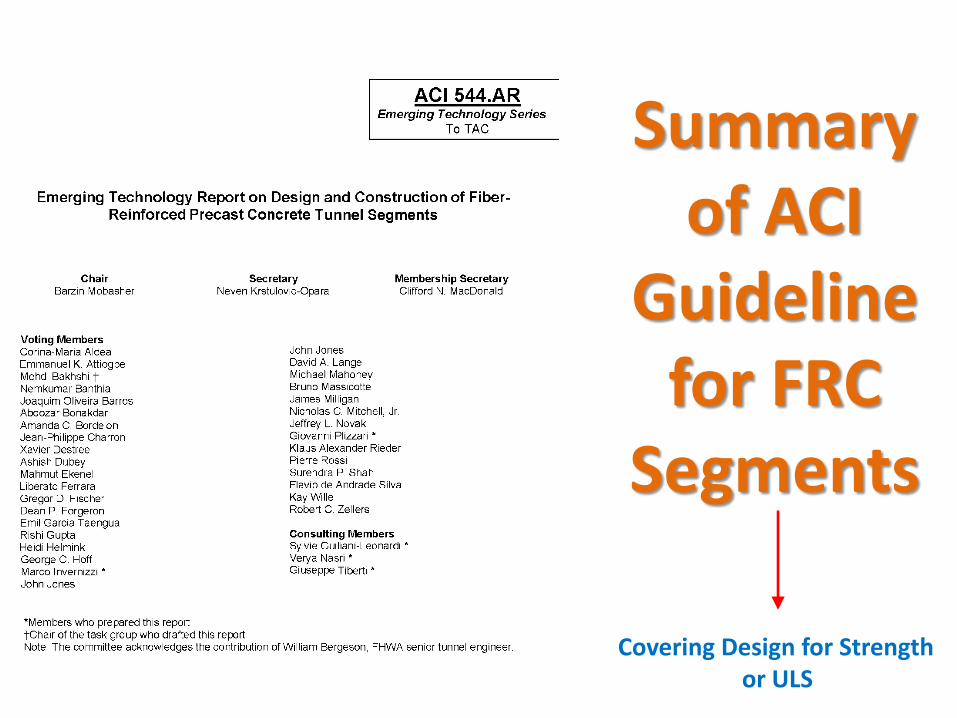
Summary of ACI
Guideline for FRC
Segments
Covering Design for Strength or ULS
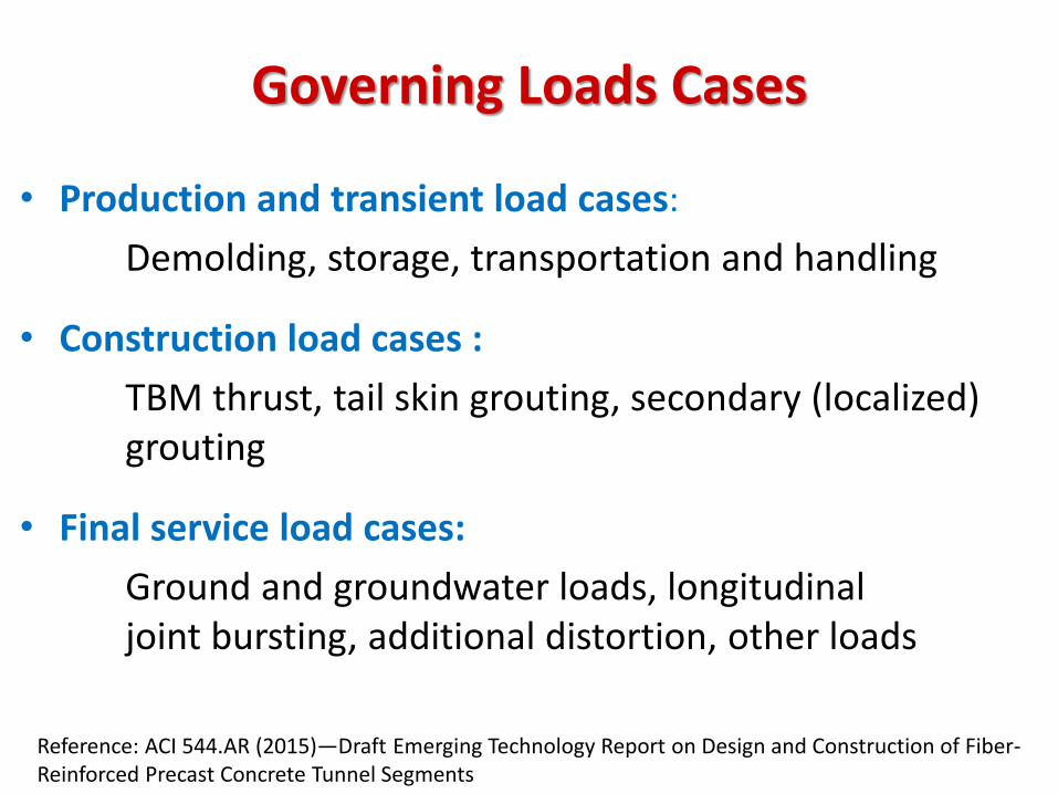
Governing Loads Cases
• Production and transient load cases:
Demolding, storage, transportation and handling
• Construction load cases :
TBM thrust, tail skin grouting, secondary (localized) grouting
• Final service load cases:
Ground and groundwater loads, longitudinal joint bursting, additional distortion, other loads
Reference: ACI 544.AR (2015)—Draft Emerging Technology Report on Design and Construction of Fiber-Reinforced Precast Concrete Tunnel Segments
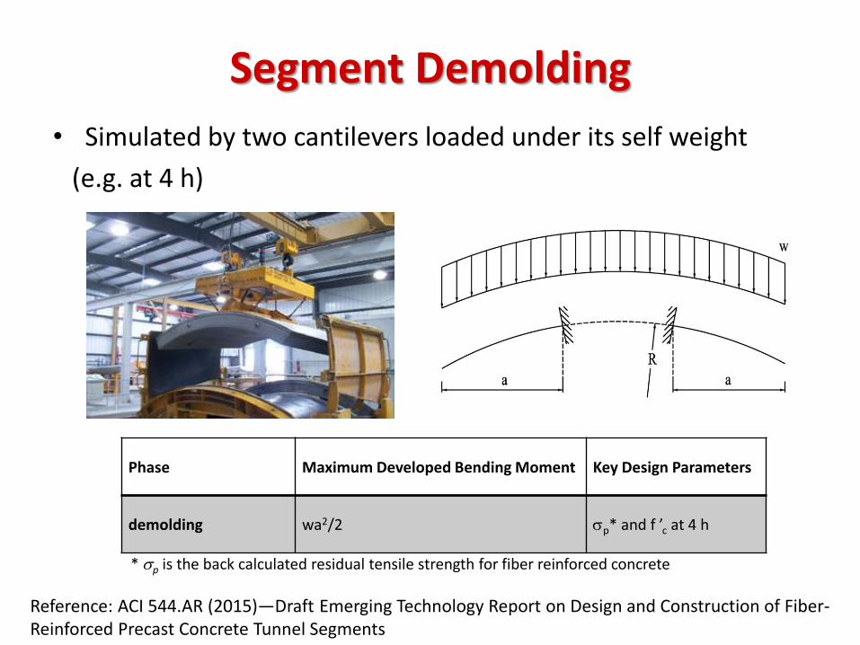
Segment Demolding
• Simulated by two cantilevers loaded under its self weight
(e.g. at 4 h)
Phase Maximum Developed Bending Moment Key Design Parameters
demolding wa2/2 sp* and f ’c at 4 h
* sp is the back calculated residual tensile strength for fiber reinforced concrete
Reference: ACI 544.AR (2015)—Draft Emerging Technology Report on Design and Construction of Fiber-Reinforced Precast Concrete Tunnel Segments
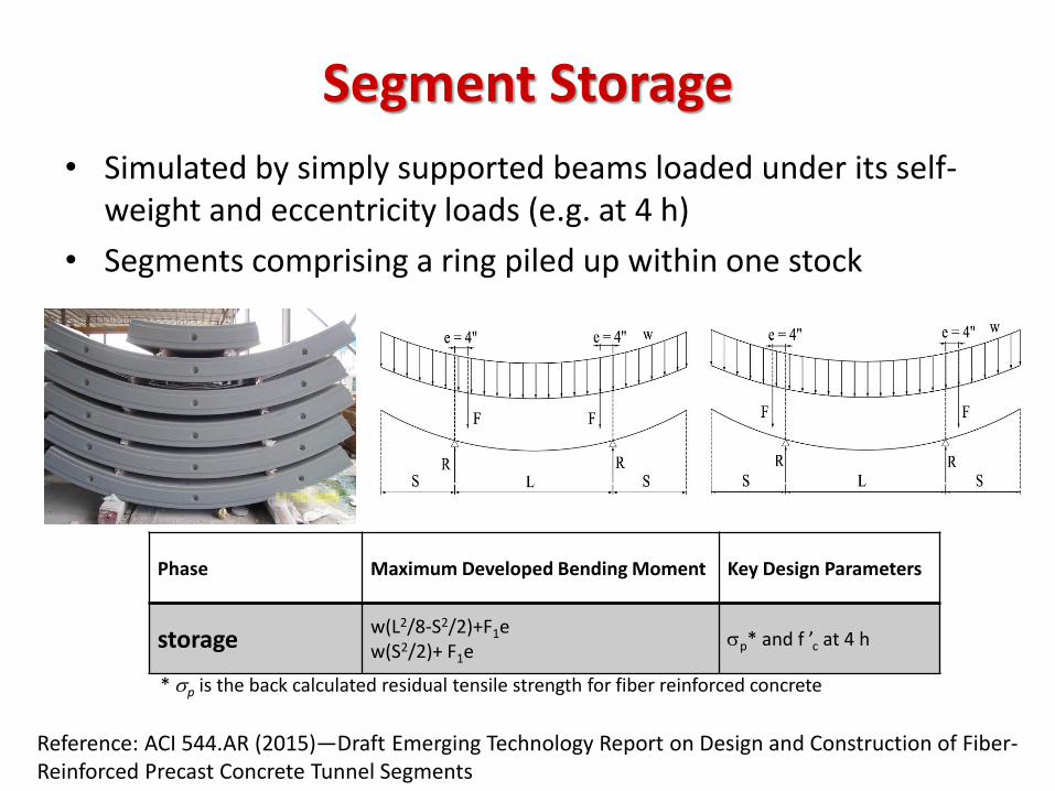
Segment Storage
• Simulated by simply supported beams loaded under its self-weight and eccentricity loads (e.g. at 4 h)
• Segments comprising a ring piled up within one stock
Phase Maximum Developed Bending Moment Key Design Parameters
storage w(L2/8-S2/2)+F1e w(S2/2)+ F1e
sp* and f ’c at 4 h
* sp is the back calculated residual tensile strength for fiber reinforced concrete
Reference: ACI 544.AR (2015)—Draft Emerging Technology Report on Design and Construction of Fiber-Reinforced Precast Concrete Tunnel Segments
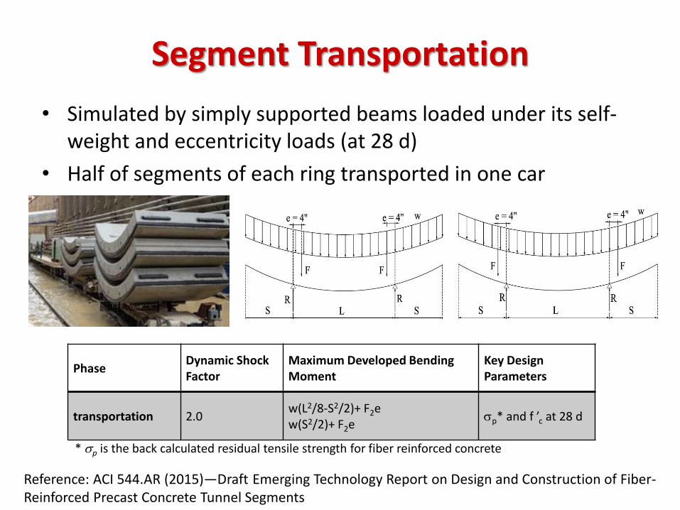
Segment Transportation
• Simulated by simply supported beams loaded under its self-weight and eccentricity loads (at 28 d)
• Half of segments of each ring transported in one car
Phase Dynamic Shock Factor
Maximum Developed Bending Moment
Key Design Parameters
transportation 2.0 w(L2/8-S2/2)+ F2e w(S2/2)+ F2e
sp* and f ’c at 28 d
* sp is the back calculated residual tensile strength for fiber reinforced concrete
Reference: ACI 544.AR (2015)—Draft Emerging Technology Report on Design and Construction of Fiber-Reinforced Precast Concrete Tunnel Segments
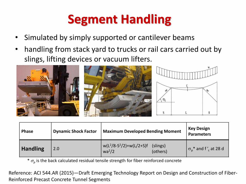
Segment Handling • Simulated by simply supported or cantilever beams
• handling from stack yard to trucks or rail cars carried out by slings, lifting devices or vacuum lifters.
Phase Dynamic Shock Factor Maximum Developed Bending Moment Key Design Parameters
Handling 2.0 w(L2/8-S2/2)+w(L/2+S)f (slings) wa2/2 (others)
sp* and f ’c at 28 d
* sp is the back calculated residual tensile strength for fiber reinforced concrete
Reference: ACI 544.AR (2015)—Draft Emerging Technology Report on Design and Construction of Fiber-Reinforced Precast Concrete Tunnel Segments
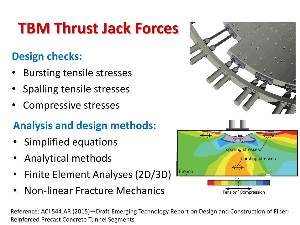
TBM Thrust Jack Forces
Analysis and design methods:
• Simplified equations
• Analytical methods
• Finite Element Analyses (2D/3D)
• Non-linear Fracture Mechanics
Design checks:
• Bursting tensile stresses
• Spalling tensile stresses
• Compressive stresses
Reference: ACI 544.AR (2015)—Draft Emerging Technology Report on Design and Construction of Fiber-Reinforced Precast Concrete Tunnel Segments
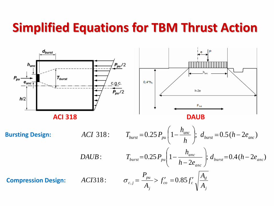
Simplified Equations for TBM Thrust Action
)2(5.0;125.0:318 ancburstanc
puburst ehdh
hPTACI
)2(4.0;2
125.0: ancburst
anc
anc
puburst ehdeh
hPTDAUB
h-2e
hanc
ACI 318 DAUB
j
dcco
j
pu
jcA
Aff
A
PACI 85.0:318 ,s
Bursting Design:
Compression Design:
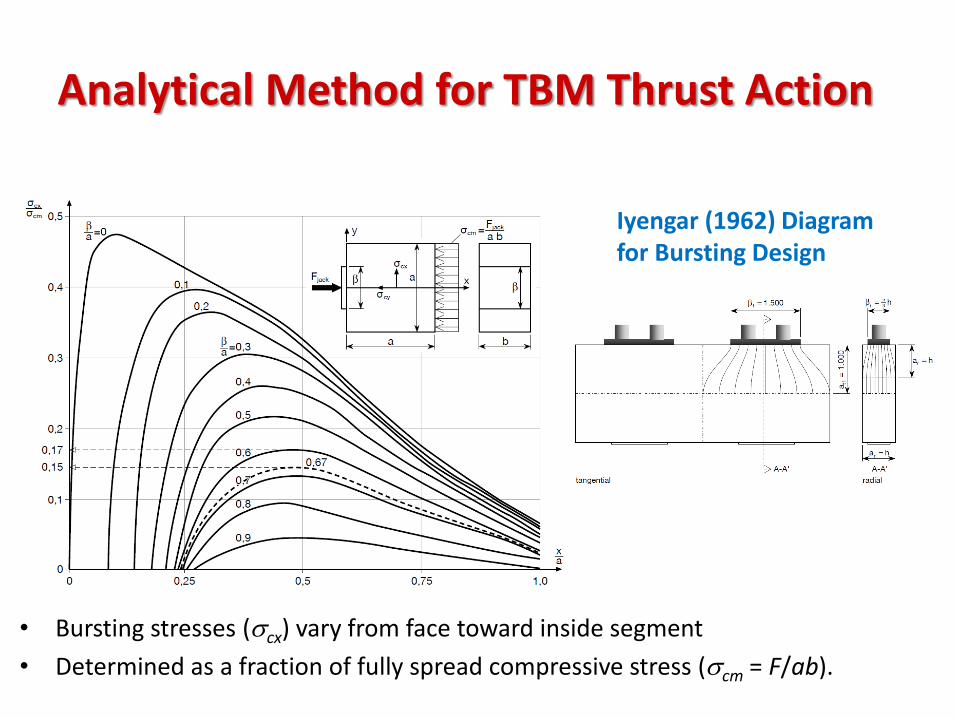
Analytical Method for TBM Thrust Action
• Bursting stresses (scx) vary from face toward inside segment
• Determined as a fraction of fully spread compressive stress (scm = F/ab).
Iyengar (1962) Diagram for Bursting Design
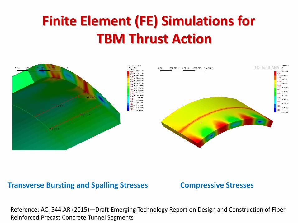
Finite Element (FE) Simulations for TBM Thrust Action
Compressive Stresses Transverse Bursting and Spalling Stresses
Reference: ACI 544.AR (2015)—Draft Emerging Technology Report on Design and Construction of Fiber-Reinforced Precast Concrete Tunnel Segments
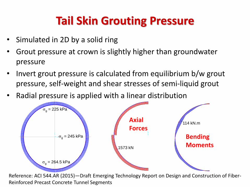
Tail Skin Grouting Pressure
sg = 225 kPa
sg = 264.5 kPa
sg = 245 kPa
114 kN.m
Bending Moments 1573 kN
Axial Forces
• Simulated in 2D by a solid ring
• Grout pressure at crown is slightly higher than groundwater pressure
• Invert grout pressure is calculated from equilibrium b/w grout pressure, self-weight and shear stresses of semi-liquid grout
• Radial pressure is applied with a linear distribution
Reference: ACI 544.AR (2015)—Draft Emerging Technology Report on Design and Construction of Fiber-Reinforced Precast Concrete Tunnel Segments
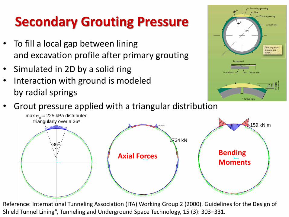
Secondary Grouting Pressure
• To fill a local gap between lining and excavation profile after primary grouting
• Simulated in 2D by a solid ring • Interaction with ground is modeled
by radial springs
• Grout pressure applied with a triangular distribution
36O
max sg = 225 kPa distributed
triangularly over a 36o
1734 kN
Axial Forces
-159 kN.m
Bending Moments
Reference: International Tunneling Association (ITA) Working Group 2 (2000). Guidelines for the Design of Shield Tunnel Lining”, Tunneling and Underground Space Technology, 15 (3): 303–331.
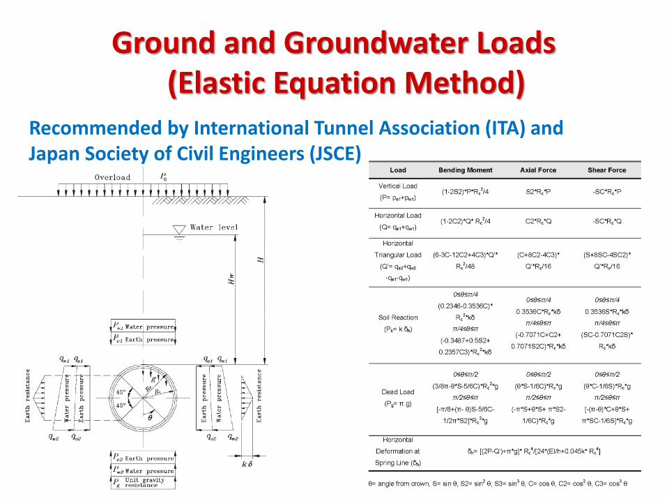
Ground and Groundwater Loads (Elastic Equation Method)
Recommended by International Tunnel Association (ITA) and Japan Society of Civil Engineers (JSCE)
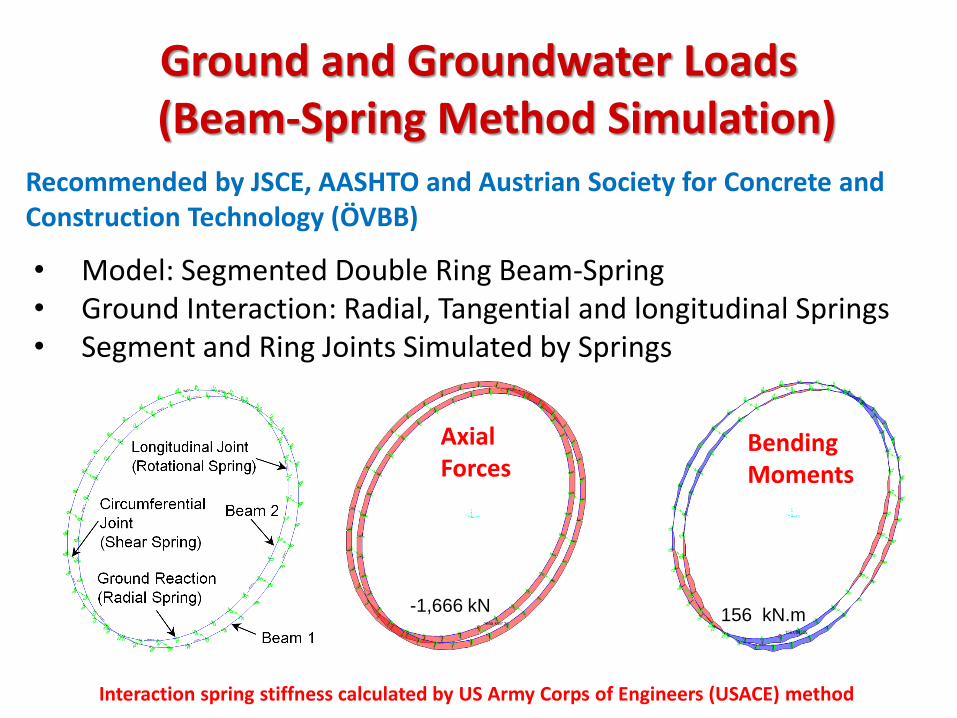
Recommended by JSCE, AASHTO and Austrian Society for Concrete and Construction Technology (ÖVBB)
• Model: Segmented Double Ring Beam-Spring • Ground Interaction: Radial, Tangential and longitudinal Springs • Segment and Ring Joints Simulated by Springs
Interaction spring stiffness calculated by US Army Corps of Engineers (USACE) method
156 kN.m -1,666 kN
Axial Forces
Bending Moments
Ground and Groundwater Loads (Beam-Spring Method Simulation)
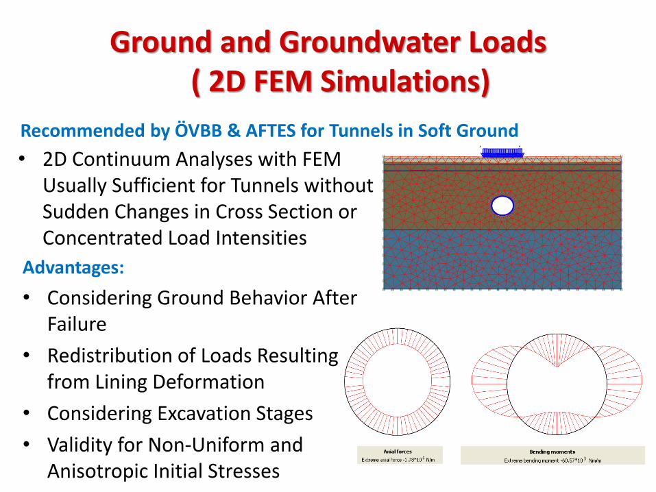
Ground and Groundwater Loads ( 2D FEM Simulations)
• 2D Continuum Analyses with FEM Usually Sufficient for Tunnels without Sudden Changes in Cross Section or Concentrated Load Intensities
Recommended by ÖVBB & AFTES for Tunnels in Soft Ground
Advantages:
• Considering Ground Behavior After Failure
• Redistribution of Loads Resulting from Lining Deformation
• Considering Excavation Stages
• Validity for Non-Uniform and Anisotropic Initial Stresses
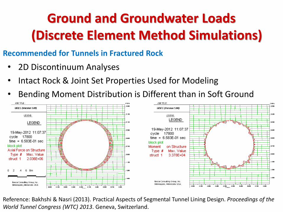
Ground and Groundwater Loads (Discrete Element Method Simulations)
• 2D Discontinuum Analyses
• Intact Rock & Joint Set Properties Used for Modeling
• Bending Moment Distribution is Different than in Soft Ground
Recommended for Tunnels in Fractured Rock
0 2 4 6 8m
Reference: Bakhshi & Nasri (2013). Practical Aspects of Segmental Tunnel Lining Design. Proceedings of the World Tunnel Congress (WTC) 2013. Geneva, Switzerland.
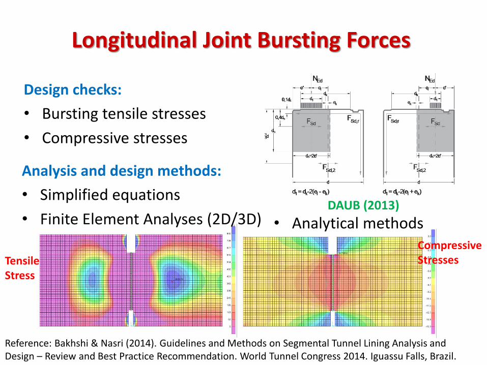
Design checks:
• Bursting tensile stresses
• Compressive stresses
• Analytical methods
Longitudinal Joint Bursting Forces
Analysis and design methods:
• Simplified equations
• Finite Element Analyses (2D/3D)
Tensile Stress
Compressive Stresses
DAUB (2013)
Reference: Bakhshi & Nasri (2014). Guidelines and Methods on Segmental Tunnel Lining Analysis and Design – Review and Best Practice Recommendation. World Tunnel Congress 2014. Iguassu Falls, Brazil.
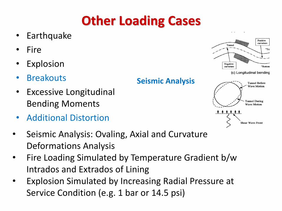
Other Loading Cases • Earthquake
• Fire
• Explosion
• Breakouts
• Excessive Longitudinal Bending Moments
• Additional Distortion
Seismic Analysis
• Seismic Analysis: Ovaling, Axial and Curvature Deformations Analysis
• Fire Loading Simulated by Temperature Gradient b/w Intrados and Extrados of Lining
• Explosion Simulated by Increasing Radial Pressure at Service Condition (e.g. 1 bar or 14.5 psi)
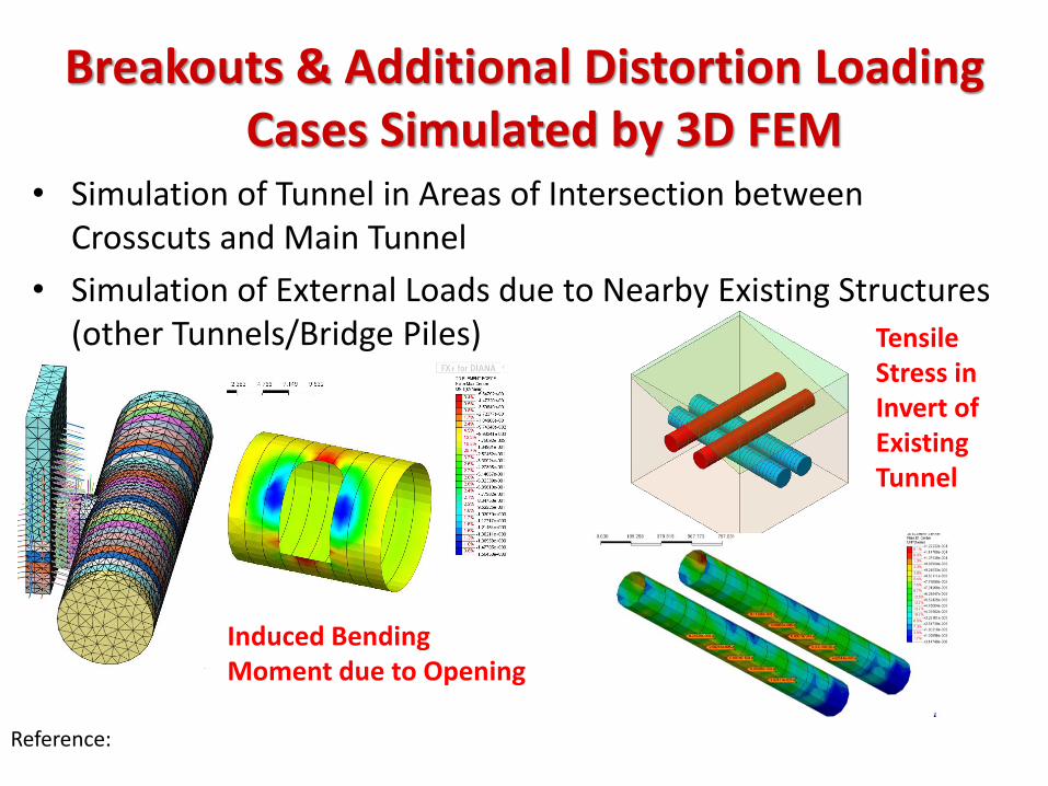
Breakouts & Additional Distortion Loading Cases Simulated by 3D FEM
• Simulation of Tunnel in Areas of Intersection between Crosscuts and Main Tunnel
• Simulation of External Loads due to Nearby Existing Structures (other Tunnels/Bridge Piles) Tensile
Stress in Invert of Existing Tunnel
Induced Bending Moment due to Opening
Reference:
Design Example for Mid-Size
Tunnels (ULS)
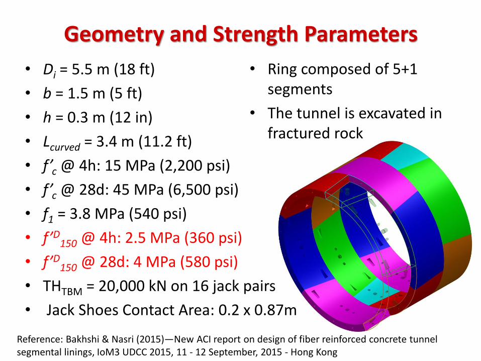
Geometry and Strength Parameters
• Di = 5.5 m (18 ft)
• b = 1.5 m (5 ft)
• h = 0.3 m (12 in)
• Lcurved = 3.4 m (11.2 ft)
• f’c @ 4h: 15 MPa (2,200 psi)
• f’c @ 28d: 45 MPa (6,500 psi)
• f1 = 3.8 MPa (540 psi)
• f’D150 @ 4h: 2.5 MPa (360 psi)
• f’D150 @ 28d: 4 MPa (580 psi)
• THTBM = 20,000 kN on 16 jack pairs
• Jack Shoes Contact Area: 0.2 x 0.87m
• Ring composed of 5+1 segments
• The tunnel is excavated in fractured rock
Reference: Bakhshi & Nasri (2015)—New ACI report on design of fiber reinforced concrete tunnel segmental linings, IoM3 UDCC 2015, 11 - 12 September, 2015 - Hong Kong
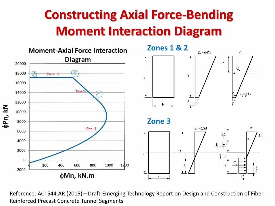
Constructing Axial Force-Bending Moment Interaction Diagram
Zones 1 & 2
Zone 3
Reference: ACI 544.AR (2015)—Draft Emerging Technology Report on Design and Construction of Fiber-Reinforced Precast Concrete Tunnel Segments
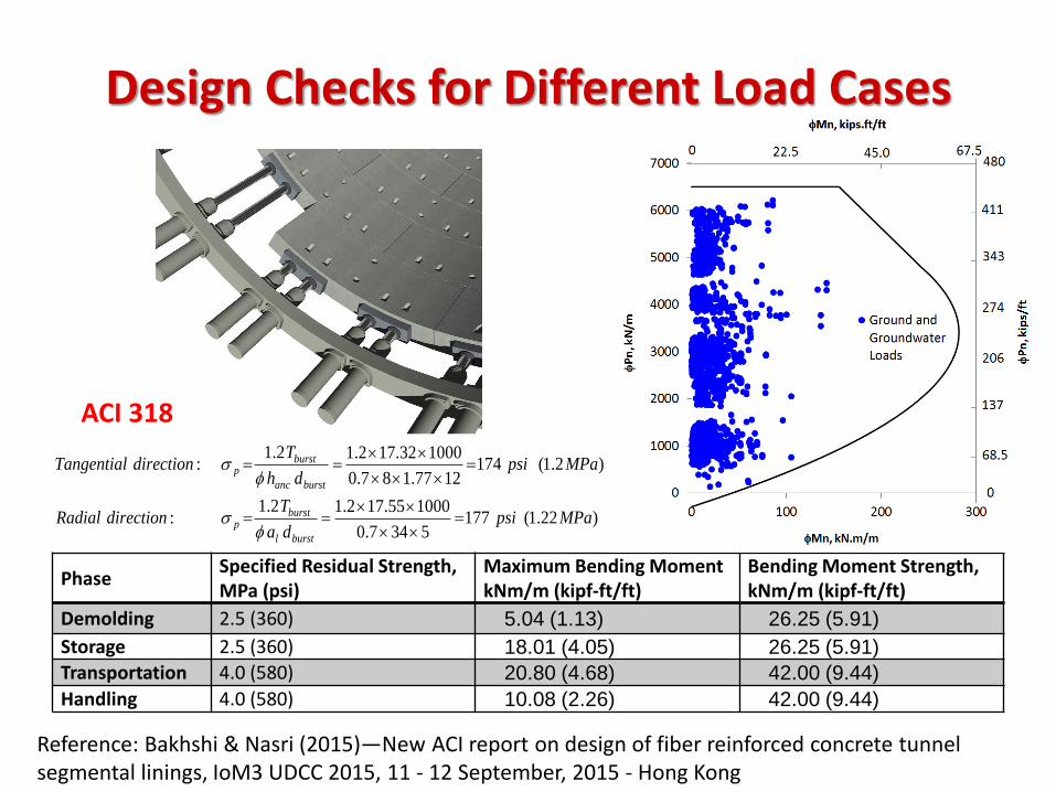
Design Checks for Different Load Cases
Phase Specified Residual Strength, MPa (psi)
Maximum Bending Moment kNm/m (kipf-ft/ft)
Bending Moment Strength, kNm/m (kipf-ft/ft)
Demolding 2.5 (360) 5.04 (1.13) 26.25 (5.91)
Storage 2.5 (360) 18.01 (4.05) 26.25 (5.91)
Transportation 4.0 (580) 20.80 (4.68) 42.00 (9.44)
Handling 4.0 (580) 10.08 (2.26) 42.00 (9.44)
ACI 318
)22.1(1775347.0
100055.172.12.1:
)2.1(1741277.187.0
100032.172.12.1:
MPapsida
TdirectionRadial
MPapsidh
TdirectionTangential
burstl
burstp
burstanc
burstp
s
s
Reference: Bakhshi & Nasri (2015)—New ACI report on design of fiber reinforced concrete tunnel segmental linings, IoM3 UDCC 2015, 11 - 12 September, 2015 - Hong Kong
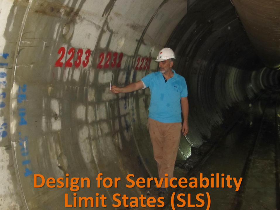
Design for Serviceability Limit States (SLS)
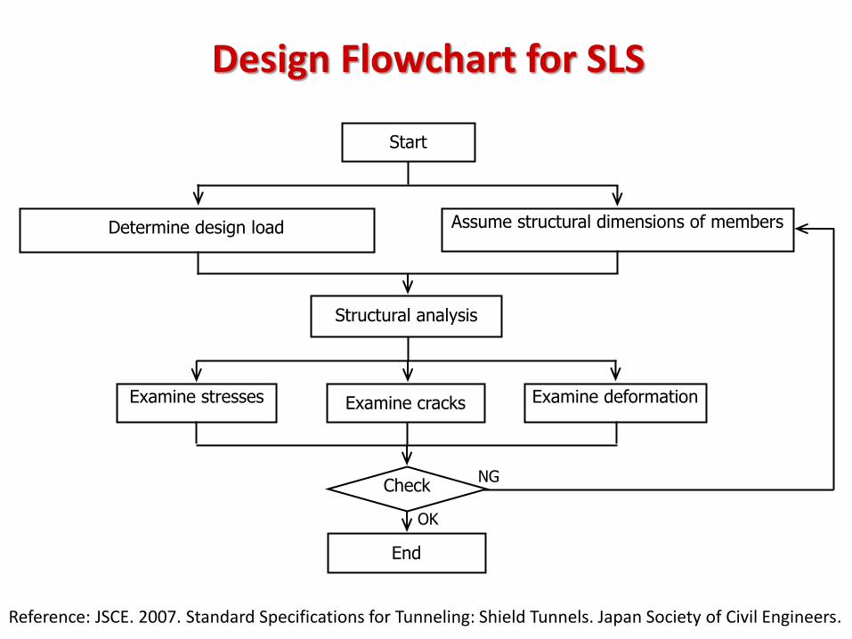
Design Flowchart for SLS
Reference: JSCE. 2007. Standard Specifications for Tunneling: Shield Tunnels. Japan Society of Civil Engineers.
OK
NG
Start
Assume structural dimensions of members Determine design load
Structural analysis
Examine cracks Examine deformation Examine stresses
Check
End
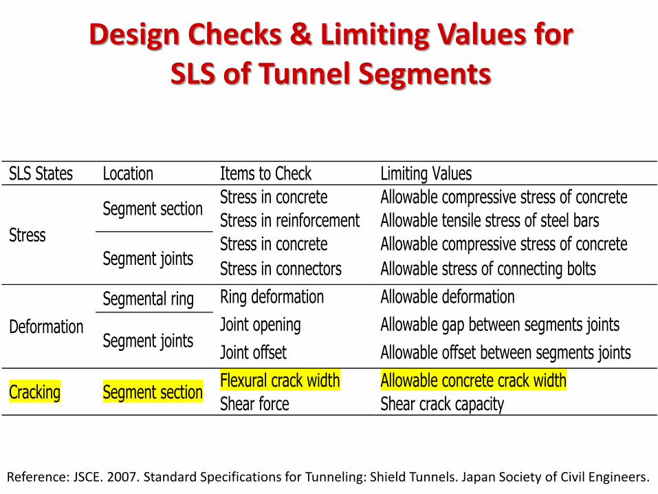
Design Checks & Limiting Values for SLS of Tunnel Segments
Reference: JSCE. 2007. Standard Specifications for Tunneling: Shield Tunnels. Japan Society of Civil Engineers.
SLS States Location Items to Check Limiting Values
Stress
Segment section Stress in concrete Allowable compressive stress of concrete
Stress in reinforcement Allowable tensile stress of steel bars
Segment joints Stress in concrete Allowable compressive stress of concrete
Stress in connectors Allowable stress of connecting bolts
Deformation
Segmental ring Ring deformation Allowable deformation
Segment joints Joint opening Allowable gap between segments joints
Joint offset Allowable offset between segments joints
Cracking Segment section Flexural crack width Allowable concrete crack width
Shear force Shear crack capacity
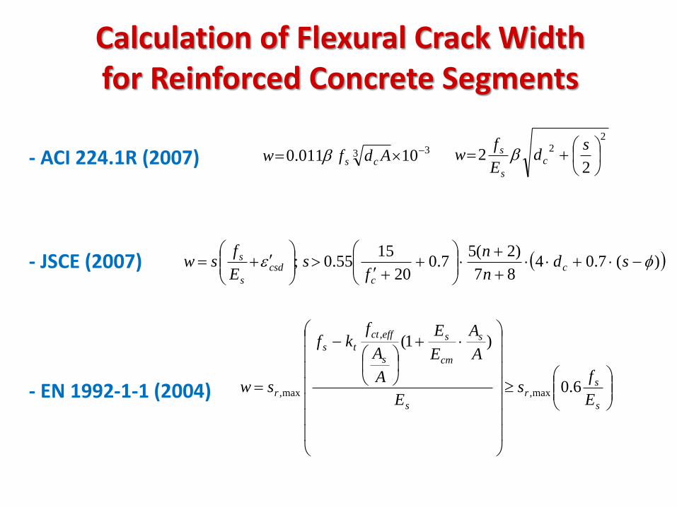
Calculation of Flexural Crack Width for Reinforced Concrete Segments
- ACI 224.1R (2007) - JSCE (2007) - EN 1992-1-1 (2004)
33 10011.0 Adfw csb
22
22
sd
E
fw c
s
s b
s
sr
s
s
cm
s
s
effct
ts
rE
fs
E
A
A
E
E
A
A
fkf
sw 6.0
)1(
max,
,
max,
)(7.0487
)2(57.0
20
1555.0;
sd
n
n
fs
E
fsw c
c
csd
s
s
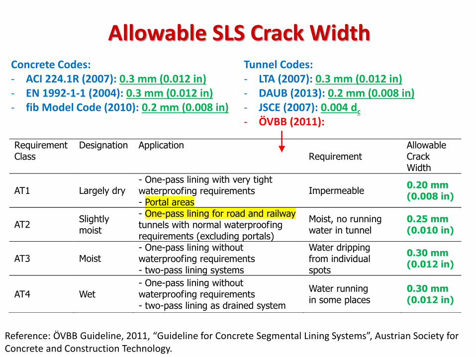
Allowable SLS Crack Width
Reference: ÖVBB Guideline, 2011, “Guideline for Concrete Segmental Lining Systems”, Austrian Society for Concrete and Construction Technology.
Requirement Class
Designation Application Requirement
Allowable Crack Width
AT1 Largely dry - One-pass lining with very tight waterproofing requirements - Portal areas
Impermeable 0.20 mm (0.008 in)
AT2 Slightly moist
- One-pass lining for road and railway tunnels with normal waterproofing requirements (excluding portals)
Moist, no running water in tunnel
0.25 mm (0.010 in)
AT3 Moist - One-pass lining without waterproofing requirements - two-pass lining systems
Water dripping from individual spots
0.30 mm (0.012 in)
AT4 Wet - One-pass lining without waterproofing requirements - two-pass lining as drained system
Water running in some places
0.30 mm (0.012 in)
Concrete Codes: - ACI 224.1R (2007): 0.3 mm (0.012 in) - EN 1992-1-1 (2004): 0.3 mm (0.012 in) - fib Model Code (2010): 0.2 mm (0.008 in)
Tunnel Codes: - LTA (2007): 0.3 mm (0.012 in) - DAUB (2013): 0.2 mm (0.008 in) - JSCE (2007): 0.004 dc
- ÖVBB (2011):
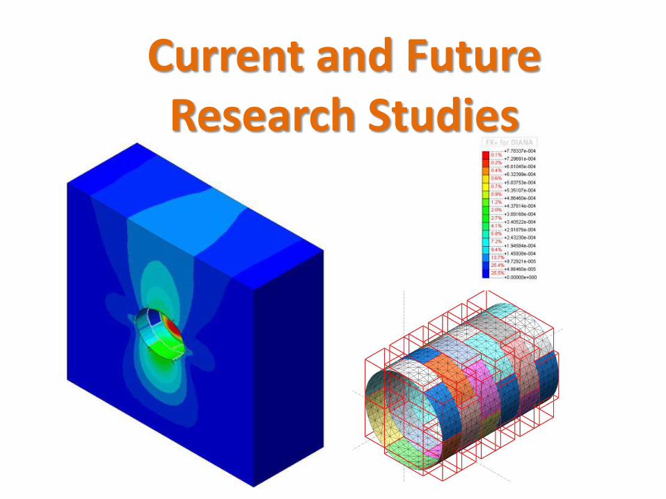
Current and Future Research Studies
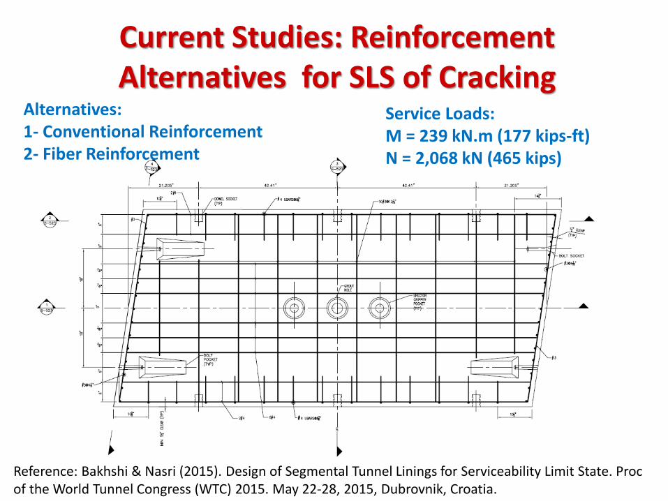
Current Studies: Reinforcement Alternatives for SLS of Cracking
Reference: Bakhshi & Nasri (2015). Design of Segmental Tunnel Linings for Serviceability Limit State. Proc of the World Tunnel Congress (WTC) 2015. May 22-28, 2015, Dubrovnik, Croatia.
Alternatives: 1- Conventional Reinforcement 2- Fiber Reinforcement
Service Loads: M = 239 kN.m (177 kips-ft) N = 2,068 kN (465 kips)
top
strains
ftop = 17.1 MPa (2.48 ksi)
stresses
Fiber properties:
f’D150 = 4 MPa (0.58 ksi)
sp = 0.34 x 4 MPa = 1.36 MPa (0.197 ksi)
1524 mm (60 in)
305 mm (12 in)
x=179 mm
(7.04 in)
fc,t
sp = 1.36 MPa (0.197 ksi)
top
st
sb
strains
ftop = 18.45 MPa
(2.676 ksi)
Fst = 1,956 kN (440 kips)
stresses
10 #4 (Asb = 1290 mm2)
10 #4 (Ast = 1290 mm2)
38 mm (1.5 in)
1524 mm (60 in)
229 mm (9 in)
305 mm (12 in)
x=148 mm
(5.8 in)
38 mm (1.5 in)
Fsb = 2,122 kN (477 kips)
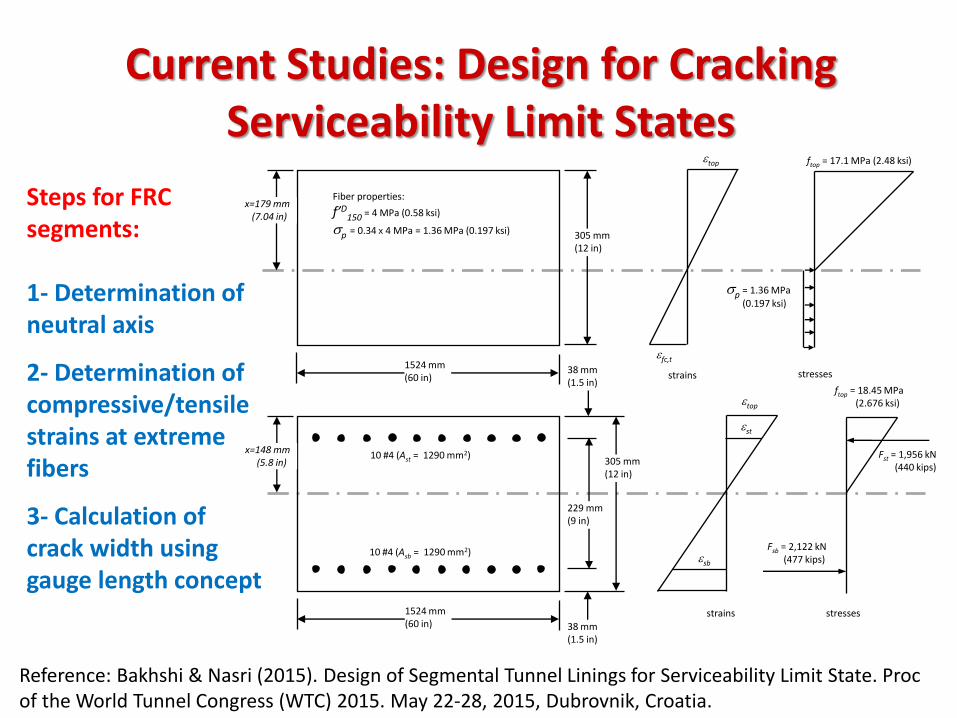
Current Studies: Design for Cracking Serviceability Limit States
Reference: Bakhshi & Nasri (2015). Design of Segmental Tunnel Linings for Serviceability Limit State. Proc of the World Tunnel Congress (WTC) 2015. May 22-28, 2015, Dubrovnik, Croatia.
Steps for FRC segments: 1- Determination of neutral axis
2- Determination of compressive/tensile strains at extreme fibers
3- Calculation of crack width using gauge length concept
hwDTCNR
CodeModelfib
tfc,:)2007(2006/204
&)2010(
)(:)2003(162 , xhwTDFTCRILEM tfc
tfcwDAfStb ,14.0:)2012(
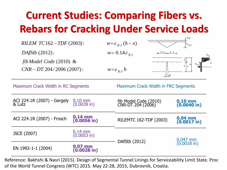
Current Studies: Comparing Fibers vs. Rebars for Cracking Under Service Loads
Maximum Crack Width in RC Segments Maximum Crack Width in FRC Segments
ACI 224.1R (2007) - Gergely & Lutz
0.10 mm (0.0039 in)
fib Model Code (2010) CNR-DT 204 (2006)
0.10 mm (0.0040 in)
ACI 224.1R (2007) - Frosch 0.14 mm (0.0056 in) RILEMTC 162-TDF (2003) 0.04 mm
(0.0017 in)
JSCE (2007) 0.14 mm (0.0053 in)
DAfStb (2012) 0.047 mm (0.0018 in)
EN 1992-1-1 (2004) 0.07 mm (0.0028 in)
Reference: Bakhshi & Nasri (2015). Design of Segmental Tunnel Linings for Serviceability Limit State. Proc of the World Tunnel Congress (WTC) 2015. May 22-28, 2015, Dubrovnik, Croatia.
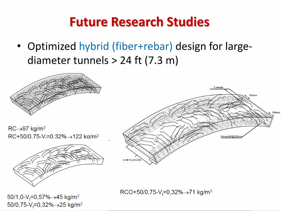
• Optimized hybrid (fiber+rebar) design for large- diameter tunnels > 24 ft (7.3 m)
Future Research Studies
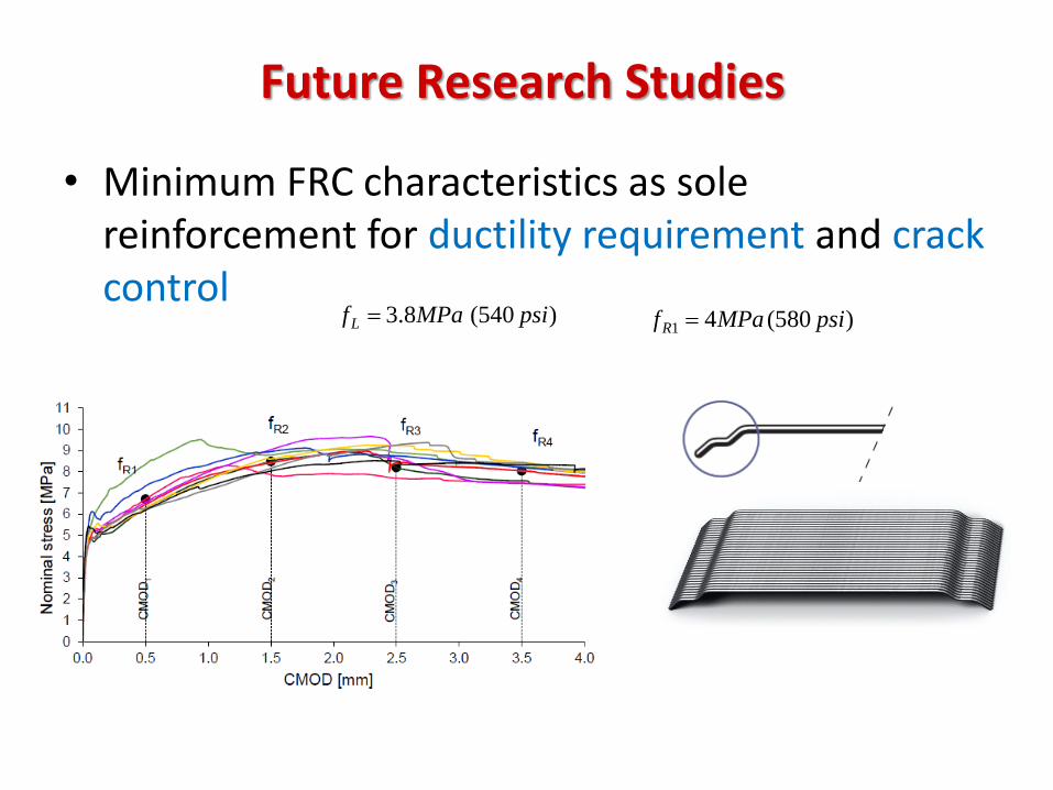
• Minimum FRC characteristics as sole reinforcement for ductility requirement and crack control
Future Research Studies
)540(8.3 psiMPafL )580(41 psiMPafR
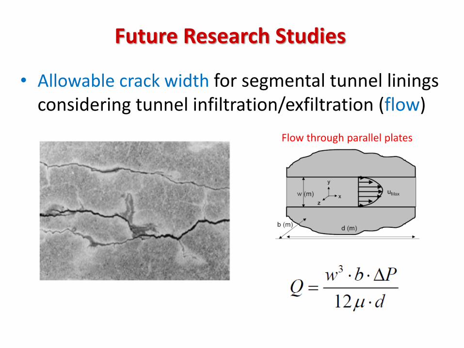
• Allowable crack width for segmental tunnel linings considering tunnel infiltration/exfiltration (flow)
Future Research Studies
Flow through parallel plates
Conclusion
• In mid-size tunnels use of fibers in segment can lead to elimination of steel bars at the ultimate limit state (ULS), which in turn results in significant construction cost saving.
• Use of fiber in tunnel segments results in reduction of crack width in under the service load for Serviceability Limit State (SLS) design.
• Different standard FRC constitutive laws give similar axial force-bending moment interaction diagrams as the key design tool for designing precast tunnel segments.

Thank you
Recommended