Design of Connections of Earthquake Resisting Precast Reinforced Concrete Perimeter Frames
68
Jose I. Restrepo, Ph.D. Post-Doctoral Fellow
Department of Civil Engineering University of Canterbury
Christchurch , New Zealand
Robert Park, Ph.D. Professor of Civil Engineering and Deputy Vice-Chancellor University of Canterbury Christchurch, New Zealand
Andrew H. Buchanan Ph.D.
Associate Professor Department of Civil Engineering
University of Canterbury Christchurch , New Zealand
Moment resisting perimeter frames are an excellent means of providing the earthquake resistance in medium heigh t multistory buildings. These frames can be constructed using precast reinforced concrete elements designed to emulate conventional cast-inplace construction. Construction of earthquake resistant buildings incorporating ductile precast reinforced concrete perimeter frames is widespread in New Zealand. The main problem in the design and construction of structures incorporating precast concrete elements to provide seismic resistance is in finding economical and practical methods of connecting the elements. This paper discusses the design and detailing of the connection region between members of earthquake resisting perimeter frames.
T he construction industry in many parts of the world has long recognized the benefits of using precast concrete members in the construction of simple and
complex structures. Precast concrete is often a very competitive alternative to other methods of construction. Economy, reduction in site formwork, speed of construction, high quality of the product, and good aesthetics are among the numerous advantages that precast concrete offers. The main problem in the design and construction of structures incorporating precast concrete elements to provide seismic resistance is in finding economical and practical methods of connecting the elements.
PCI JOURNAL

Recent tests'-5 have shown that moment resisting frames incorporating precast concrete elements can be designed to perform adequately during strong earthquakes. Coordinated research programs such as PRESSS (Precast Seismic Structural Systems)6
and ATLSS (Advanced Technology for Large Structural Systems)? have contributed to the design and understanding of the response of precast concrete structural components in buildings in seismically active regions.
It is generally accepted that the most viable solution for the design of buildings for earthquake resistance is to allow the structure to respond beyond the elastic range in the event of a major earthquake. Thus , the inertia forces induced in the building responding in the post-elastic range are significantly smaller than those associated with the elastic response. Period shift, increased damping, and hysteretic energy dissipation, among several factors , are used to explain the above phenomena.
This paper discusses the design of connections between relatively deep precast reinforced concrete beams of ductile perimeter frames for seismic resistance.*
PHILOSOPHY FOR THE DESIGN OF
PRECAST CONCRETE PERIMETER FRAMES
Precast concrete perimeter frames in New Zealand are generally designed as ductile structures . 8-9 Their design follows the requirements of the Code of Practice for General Design, NZS 4203:1992, 10 and the Concrete Structures Standard, NZS 3101 :1995."
NZS 4203: 1992 contains the general loading and design requirements, including those for earthquakes, load combinations, and interstory drift control. NZS 3101 :1995 contains the provisions for the detailing of the reinforcement of concrett:; structures.
The lateral forces at the ultimate limit state required for the design of ductile moment resisting frames of buildings obtained from NZS 4203: 1992 are comparative! y similar to the
* Appendix A includes several design examples.
September-October 1995
Cast-in-place concrete
Precast concrete beam
Fig. 1. System 1 with precast concrete beam elements seated on cover concrete of column.
ultimate forces required by the Uniform Building Code (UBC)' 2 for the design of special moment resisting frames .
Precast reinforced concrete perimeter frames are widely used in New Zealand to provide the required earthquake resistance of medium height multistory buildings. The beams and columns in these frames are relatively stout. An advantage of using perimeter frames is that the depth of the beams, being outside the services and ceiling areas , may be large without compromising the story height. The interior frames in such a design carry mainly gravity loading because they are flexible in relation to the perimeter frames . The columns of the interior frames are detailed to accommodate the deformation requirements of the interstory displacements, including the local displacements due to the flexibility of the diaphragm and due to the relative interstory rotation between consecutive floors .
New Zealand practice favors the use of precast concrete systems with castin-place concrete joints designed to emulate conventional cast-in-place concrete construction.5
·8·9 For this type
of construction, it is necessary to ensure that the connections between precast concrete members will not compromise the assumptions made in the design of the structure.
The success and widespread use of precast co ncrete in providing the earthquake resistance in buildings in New Zealand relies on a thorough understanding of the capacity design philosophy .8·" Capacity design ensures that the most desirable mechanism for energy dissipation, chiefly by ductile flexural yielding at selected plastic hinges, can develop and be maintained during the seismic event. The other regions of the structure, which need not be designed for ductility, are deliberately made overstrong to ensure that they will not jeopardize the strength nor the ductility of the selected mode of plastic deformation.
DESIGN OF CONNECTIONS
This section discusses the design of beam-to-column connections and midspan connections.
Beam-to-Column Connections for Precast Beam Units Placed Between Columns
This precast concrete arrangement is known in New Zealand as System 1.5
•8·9 The beams span from column to
column and are often seated on the concrete cover of the column below (see Fig. 1). The beam longitudinal bottom bars are bent upwards in, or
69

Corrugated duct
Grouted duct and joint
Precast concrete beam
Cast-in-place concrete joint at midspan
Column
Fig. 2. System 2 with precast concrete beams passing through columns.
immediately outside, the beam-tocolumn joint region. Construction details for this system are given in Refs. 5, 8, and 9.
Tests5·'
4 on this precast concrete system, in which the beams are seated a certain distance on the cover of the column below, have shown a similar performance to cast-in-place concrete construction. This is because the main crack in the beam at the column face forms in monolithic concrete and not through the construction joint. To prevent this crack from forming at the vertical cold joint, it is recommended that the beam be seated on the cover concrete of the co lumn below a distance sd (see Fig. 1) such that:
(Ia)
and
(lb)
and
sd ::=: 30 mm (1.2 in.) (lc)
where bw is the width of the beam, hb is the beam depth, and V0 is the beam shear force at the column face, corresponding to the development of the flexural overstrength. The flexural overstrength is generally assumed to be 1.25 times the nominal flexural strength calculated with the longitudinal beam reinforcement as detailed.
The hooked bottom bars need to be anchored at the far side of the joint
core. The overlapping length, lsh' between the hooked bars (defined as shown in Fig. 1) should be not less than:
where db is the diameter of the hooked bar, g is the clear cover to the extension of the hook, measured in the plane of the hook, and ldh is the development length of the hooked anchorage.
Beam-to-Column Connections for Precast Beam Units Passing Through Columns
In this system, the precast portions of the beam extend from midspan to midspan, as shown in Fig. 2. The beam-to-column joint region is included in the precast concrete beam. The column bars pass through corrugated stee l ducts in the beam-to column joint (see Fig. 2) . The ducts and the gap between the precast concrete beam unit and the column below are grouted.5
·8•9
The midspan connections for this system are generally achieved by short connection details in a cast-in-place joint. Fig. 3 shows two such connection details used in perimeter frames of existing buildings in New Zealand.
In New Zealand, it is recommended that the compressive strength of the grout be 10 MPa (1450 psi) greater than the compressive strength of the
(a) Connection with overlapping hooks (b) Connection with drop-in double hooked bars
Fig. 3. Construction details for cast-in-place midspan connections in short beams of precast concrete perimeter frames in New Zealand .
70 PCI JOURNAL

concrete of the precast concrete beams.9 The grouting operation should be done very carefully. For example, the concrete in the void to be grouted should be saturated with water for at least 6 hours prior to grouting. Also, the operator should ensure that the grout fills all the empty spaces and that it does not segregate.5
Midspan Connections Between Short Beams
Beams of perimeter frames of medium height multistory buildings generally have small aspect ratios. In these beams, the effects produced by gravity loads are insignificant when compared with those induced by lateral earthquake actions. Thus, these beams are designed with equal top and bottom longitudinal reinforcement. Also, the point of inflection remains very close to the beam midspan.
A problem with connecting short beams is that the connection detail cannot extend into the critical end regions of the beams. The current ACI 318 Code'5 and the first edition of the former New Zealand Concrete Design Code, NZS 3101:1982, '6 do not allow splices to commence at less than two times the effective beam depth , d, from the critical region. Thus, the clear span of beams designed according to the ACI 318 Code or the first edition of NZS 3101: 1982 has to be at least 4d + lu where lc is the length of the connection.
In practice, to satisfy this requirement for short beams, it is necessary to reduce as much as possible the length of the connection to a minimum. The amendment of NZS 3101: 1982 and the newly issued NZS 3101:1995" relaxed this limit to d as a result of tests on short precast reinforced concrete beams with splices that extended into the 2d region.5
It has long been recognized that in cracked reinforced concrete beams , the tension force in the longitudinal reinforcement cannot be directly estimated from the M/jd diagram. 17 This is due to the interaction between flexure and shear after diagonal cracking . Fig. 4 illustrates this interaction for a typical short beam of a laterally loaded perimeter frame.
September-October 1995
(B) Loaded beam snd equivalent truss model
(b) Bending moment disgrsm
(c) Free body
(d) Tensile force disgrsm
Fig. 4. Truss model for a short beam of a perimeter frame.
Fig. 4(a) shows an assumed truss model to represent the flow of internal forces in the beam after cracking has occurred. According to this truss model, the concrete in the beam carries the shear force through a diagonal compression field of stresses inclined at an angle 8 to the horizontal. Vertical steel ties provide the necessary reaction forces to sustain the diagonal stress field.
Fig. 4(b) shows the bending moment diagram in the beam resulting from gravity loads and the earthquake actions. In short beams, gravity loads have a small relative effect and can be disregarded in practice.
When gravity loads are ignored, the tension force, T', in the top beam reinforcement at a distance, x, from the beam midspan, can be found from equilibrium considerations (for derivation of Eq. (3), see Appendix B):
T' = (x + _1!!_) vo (3) 2tane jd
which is valid for the interval:
l/, jd jd ----~x~---2 2tane 2tane
where a parallel diagonal stress field exists.
The tensile force in the top beam reinforcement in the region:
Where a fanned stress field is present, this force can be assumed to be equal to the force T0 at the beam end.
The term on the right-hand side inside the parenthesis in Eq. (3) is known as the tension shift. 17 Codes 11
•15
tacitly recognize the tension shift. This is because they require the longitudinal reinforcement to be extended a distance d beyond the theoretical point in the bending moment diagram where it is no longer needed to resist flexure.
Note that when x = 0 in Eq. (3):
T'=~ 2tan8
71

1-bw-!
/-v
Fig. 5. Truss model for a midspan connection using overlapping hooks.
This tensile force will exist in both the top and bottom longitudinal reinforcement at midspan. That is, a connection at midspan of a short beam will need to resist the tensile force T' if the shear is high enough to cause diagonal tension cracking there.
For the evaluation of Eq. (3), it will be assumed here that e = 35 degrees. This angle is an approximation to the inclination of the diagonal compression field of stresses in beams designed with the conventional additive concrete and 45-degree truss mechanisms.
Midspan Connections With Overlapping Hooks
A truss model for the connection detail involving overlapping hooks is illustrated in Fig. 5. The total shear force in the beam needs to be locally transferred by vertical ties between the top and bottom hooks because, in the model, any splice action between the hooked bars that overlap is disregarded.
Substituting X = 0 and e = 35 degrees into Eq. (3) gives:
T' = 0.7V0 (5)
This is the force in the longitudinal reinforcement that has to be resisted by the overlapping hooks at midspan.
Substituting T' from Eq. (5) into Eq. (4) gives:
(6)
tJ - -Section A-A
tJ - ~N Short / ~ transverse 2.5db rod
Section 8-B
Fig. 6. Effect of transverse rods in enhancing the anchorage conditions in bars terminated with a standard hook.
The effective bearing area is equal to the diameter of the bend of the hooked bars, s, multiplied by an effective width of beam bw - 2c0 (see Fig. 5). On this basis, the bearing stress is:
where c0 is the concrete cover to the hooked reinforcement measured from the side of the beam.
Substituting Eq. (6) into Eq. (7) , assuming bw - 2c0 == 0.75bw and rearranging for s gives:
S = 1.64V0
bwfb
-/ /
/
/
-
(8)
Also, the bend diameter of the hooked bars should be sized to avoid a premature bearing failure of the concrete strut radiating from the hook. Accordingly, the calculated stresses should be limited to a value related to the unconfined compressive cylinder strength of the concrete, .f The magnitude of the resultant diagonal compression force, D 0
, is found from Fig. 5: Fig. 7. Truss model for a midspan connection using drop-in double hooked bars.
72 PCI JOURNAL

NZS 3101:1995 '' recommends that for this noda l zone, the maximum bearing stress permitted is fb = 0.551/>J:. Substituting this value into Eq. (8) and using a strength reduction factor 1/> = 1 for a capacity designed element'' results in the following minimum value permitted for ~:
vo ~-3-
bwf: (9)
The value for ~ should not be taken smaller than the minimum diameter of bend for standard hooks permitted by the design standards. 11
•15
Radial stresses in hooked anchorages may reduce the compressive strength of the concrete diagonal strut in the connection region by inducing a premature sp litting fai lu re . Short transverse rods in contact with the inside of the bend distribute the radial stresses, as illustrated in Fig. 6 and, hence, minimize the detrimental effect of those stresses. These rods should be of the same diameter as the hooked bars.
Hence, in summary for the design of midspan connections with overlapping hooks:
1. The beam shear force V0, corre
sponding to the development of the flexural overstrength, needs to be transferred by vertical ties (stirrups) between the top and bottom hooks.
2. The longitudinal reinforcement being overlapped should have a tensile capacity of at least 0.7 V0
•
3. The minimum value for the diameter of bend of the hooks to limit the stresses of the diagonal strut bearing against the hooks is given by Eq. (9).
4. Transverse rods in contact with the inside of the hooks should be present in the connection region. The rods should be of the same diameter as the hooked bars.
Midspan Connections With Drop-in Double Hooked Bars
This connection detail and a truss model are shown in Fig. 7. According to the truss model, the shear force in the beam, V0
, should be transferred by vertical ties along the connection region.
The truss model indicates that some splice action between the top and bot-
September-October 1995
Beam axis {Plane of symmetry)
\.
T' • n
T' n .... .__
Hooked bars protruding from the precast beam
Horizontal ties (minimum two per overlap)
"Drop In" double hooked bars
n=4
(a) Free body diagram
I I I I
T" --T' -- I Sl'. 1.., 9A.
n n I ..., .... I
I I I I
' Itt .. 9>-
T" --n T' n---~'-T") (b) Truss model
Fig. 8. Transverse reinforcement required at the overlapping of the hooked bars in a drop-in double hooked connection .
tom drop in bars is required for equilibrium. A fanned stress field spreads through the length of the splice at an angle varying from f) to fJ". The resultant diagonal fo rce, D 0
, acts at an angle 8' which lies between 8 and 8". The force T" in the drop-in double hooked bars is from Fig. 7:
T" = T'- L1Vo tan8'
(10)
where tan 8 ' = V0 /T' and L1V0 is the fraction of the beam shear force transferred by the set of stirrups along one overlap.
A practical layout of the transverse
reinforcement in this region is to have five sets of stirrups arranged as shown in Fig. 7. Two of the five stirrups carry part of the beam shear force in each overlap. This implies that L1 V0 = 0.4 V0
• Thus, for this layout of stirrups, Eq. (10) can be rewritten as:
T" = 0.6T' (1 1)
The tension force, T', can be calculated assuming that the offset distance from the beginning of the hook to the point of inflection is 0.2jd. This is a reasonable assumption for the dimensio ns norma ll y used in perimeter beams. Hence, substituting Eq. (3)
73

Fig. 9. Assumed effective friction surface in the overlapping region of a drop-in double hooked connection.
into Eq. (11), and putting () = 35 degrees and x = 0.2jd results in:
T' = 0.91 V0 (12a)
and
T" = 0.55V0 (12b)
Enough longitudinal reinforcement should be present in the overlapping region to ensure that the forces T' and T" can be developed. Also, the force T" needs to be transferred from the drop-in double hooked bars to the protruding hooked bars by an interface shear transfer mechanism in the lap region. The shear-friction concept will be used below to develop equations for the design of this connection.
Fig. 8 depicts a free body diagram of the region at the overlap between the hooked bars protruding from a precast beam and the drop-in double hooked bars. The connection shown in Fig. 8(a) consist of four overlapping bars, two at each side of the vertical plane passing through the beam axis . The connecting bars are arranged symmetrically with respect to this vertical plane.
Fig. 8(b) shows a simple tru ss model of the connection. The forces between the lapped bars are transferred through a diagonal compression field that requires transverse reinforcement (ties). The compression field between sets of lapped bars is perpendicular to the beam axis . As a result, a strain incompatibility must arise to enable this compression field to act parallel to the transverse reinforcement. Bar slip and controlled width splitting cracks at the level of the ties is expected to occur. These cracks have been observed in tests in these types of connections5 and present no detrimental effects.
According to the shear-friction concept, the area of transverse reinforce-
74
Beam midspan
T~----
(a) Elevation
L~ n
Horizontal tie
(b) Plan view
Fig. 10. Diagonal compression fields acting along a midspan straight splice.
ment, A sP required at each overlap between the protruding bars and the drop-in double hooked bars is:
(13)
where f yz is the yield strength of the transverse reinforcement and f.Lt is the coefficient of friction.
Combining Eqs. (12b) and (13) and putting f.Lt = 1.4 for monolithic concrete and l/J = I results in:
vo A51 =0.2- (14)
!yt
It is recommended that at least two horizontal ties with a total area of at least A 51 surround each overlapping region, as Fig. 8(a) shows.
The current New Zealand and ACI codes"·15 limit the shear stress in the concrete at the development of the shear-friction mechanism to avoid a premature crushing failure. This limit is the smaller of 0.21; or 6 MPa (870 psi).
An approximation of the effective friction surface, A T, where lapping action occurs, is depicted in Fig. 9:
where T] is the lapping distance measured between the centerlines of the extension lengths of the hooks . The
lapping di stance, T), should not be taken to be less than the minimum diameter of the bend given in design standards plus one bar diameter.
The average shear stress, -.1, acting on the effective friction surface, AT, is:
T" '"t =-
nAT (16)
in which n is the number of drop-in double hooked bars transferring the force T".
Substituting Eqs. (12b) and (15) into Eq. (16) and rearranging forT] gives:
(17)
Now substituting the limit stresses for -r1 results in T] being the greater of:
or
vo 1]=0.6-
nf:db
vo T]=-- mm
50ndb
[ V
0
0 ] T]= m. 7250ndb
(18a)
(18b)
Hence, in summary, for the design of midspan connections with drop-in double hooked bars:
PCI JOURNAL

1. The beam shear force, yo, corresponding to the development of flexural overstrength, should be transferred by vertical tension ties (stirrups) between the top and bottom hooks along the length of the connection region.
2. The longitudinal reinforcement being overlapped should have a tensile capacity of at least 0.91 yo [Eq. (12a)]. The drop-in double hooked bars should have a tensile capacity of at least 0.55Y0 [Eq. (12b)] , when a five-stirrup arrangement is present around the connection (see Fig. 7).
3. The area of the surrounding transverse reinforcement required to transfer the forces between the overlapping hooks is given by Eq. (14), only if the connection region is symmetrically arranged along the vertical plane passing through the beam axis. At least two ties should surround each overlapping region [see Fig. 8 (a)]. Eq. (18) should be used to check that the overlapping distance is adequate.
Midspan Connections Using Straight Bar Lap Splices
Straight bar splices result in a simple and effective connection detail. Two main arrangements using straight lap splices are commonly found in New Zealand. In the first arrangement, the straight bars protruding from the opposite precast concrete beams overlap side by side, forming non-contact lap splices. In the second arrangement, the bars end face-to-face and do not overlap. The splice is achieved by placing additional straight bars to form a double straight lap.
The design procedure for finding the required length of straight bar splices, as well as the transverse reinforcement around them, can be derived using the shear-friction concept. The procedure is similar to that used in the previous connection.
Fig. 10 shows the connection region between two precast concrete beams at the beam midspan. The protruding longitudinal bars of the precast concrete beams are lapped side by side forming a non-contact splice. The separation between the bars is s1•
Fig. lO(b) depicts the diagonal compression field of stresses acting in the horizontal plane between the lapping
September-October 1995
bars. These fields transfer the force T" between the lapping bars through interface shear mechanisms. The truss model shown in Fig. 8(b) is also applicable to the lap splice shown in Fig. 10. Therefore, Eq. (13) gives the area of transverse reinforcement required to cross the potential crack along the lapped bars.
For a midspan connection with straight bar lap splices, it is convenient and conservative to assume that the force T" at the end of the splice is equal to the force T' at the beam midspan. This assumption has the advantage of uncoupling force T" from the length of the splice. It also gives the exact solution for a double straight lap.
Therefore, the area of transverse reinforcement, A51 , required to surround the lapped connection is found by making T" = T' in Eq. (13), combining Eq. (12b) and Eq. (13) and substituting</>= 1 and f.lt= 1.4:
yo A51 = 0.25- (19)
fyt
The above equation assumes that the spliced bars are symmetrically arranged along the vertical plane passing through the beam axis [see Fig. lO(b)].
The effectiveness of the transverse reinforcement in providing the necessary clamping force to develop the shear-friction mechanism diminishes the farther the lapping bars are located away from this reinforcement. For this reason, it is recommended that the horizontal legs of closed stirrups only be considered fully effective in providing the necessary reinforcement area required by Eq. (19) if the lapped bars are located at less than 100 mm (3.93 in.) from the horizontal tie leg. Fig. 11 graphically represents this recommendation.
The length of the lap splice can be derived from an effective friction surface over which the force in the lap is transferred. Paulay 1
" assumed that the effective friction surface is equal to the basic length of the lap splice, lsb• multiplied by a width of 3db.
Thus, the effective friction surface, AP is given by:
The force, Tb, in an individual bar in the splice is:
where Ab is the section area of the bar, r; is the tensile capacity of the lapped bars as provided, and fy is the yield strength of the lapped bars.
The shear stress, -r1, between a pair or lapped bars is found by dividing the force Tb given by Eq. (21) by the effective friction surface of Eq. (20):
A T' -r- b f, f -3d[ T' y
b sb p (22)
The basic length of the lap splice to avoid crushing of the concrete at the development of the shear-friction mechanism is obtained by substituting the code 11
•15 limiting values of 0.2J; or
6 MPa (870 psi) for -r1 into Eq. (22) and making Asb = n dt,/4. Thus:
or
T' f, lsb = _ _Ldb mm (23b)
T' 23 p
[l - T' f y d ·] sb- r; 3300 b m.
The length of the lap splice, l5 ,
should account for the offset of the lapped bars [see Fig. lO(b)]. The angle of inclination e of the diagonal stress field developed between the lapped bars is equal to tan-1(1/f.lt). Consequently, the value for l5 when f.lt = 1.4 is from Fig. lO(b):
ls = lsb + 1.4s1 (24)
The length of the splice given by Eq. (24) should not be less than 300 mrn (11.8 in.).
Eq. (23) was derived based on the assumption that a uniform clamping stress acts in the longitudinal bars between ties. A tied longitudinal bar can be idealized as an infinitely long beam on an elastic foundation. It can be shown that uniform stresses will act on a longitudinal bar when the spacing between ties is less than 3.5db on average, where db is the diameter of the longitudinal bar.
When the tie spacing increases, the clamping stresses become nonuniform
75

Lapped bars
Fig. 11. Spacing between the spliced bars and the transverse reinforcement providing the clamping force to enable the shear-friction mechanism to be developed.
and concentrate at the contact points between the ties and the longitudinal bar. In order to keep the peak clamping stresses below the crushing stress, it is recommended that the spacing, s, between ties be no more than:
where
and lsp is the length of lap splice provided in the design.
Hence, in summary for the design of midspan connections with non-contact splices with straight bars lapped in horizontal planes:
1. The longitudinal reinforcement being spliced should have a tensile capacity of at least 0.7V0 [Eq. (5)].
76
2. The length of the lap splice , Is, should at least be that given by Eq. (24) or 300 mm (11.8 in.), whichever is greater.
3. The area of transverse reinforcement required to sustain the interface shear transfer mechani sm between lapped bars is given by Eq. (19). The spacing of the ties should not exceed the value computed from Eq. (25).
4. Lapped bars should be considered to be fully clamped by the horizontal legs of c losed stirrups only when located within a vertical distance of no more than 100 mm (4 in.) from horizontal legs (see Fig. 11).
CONCLUSIONS 1. The main objective of this paper
is to establish rational procedures for the design and detailing of connections between precast reinforced concrete elements for use in earthquake resisting ductile perimeter fra mes . This paper fulfills that objective.
2. Two structural systems and their connections are studied in this paper. The connections between the precast concrete elements are achieved in cast-in -pl ace co ncrete or grouted joints. These systems are commonly designed in New Zealand to emulate monolithic construction.
3. In some perimeter frames incor-
porating precast reinforced concrete elements, it is necessary to design short joints to connect stout beams at midspan. A problem with connecting some short precast concrete beams at midspan is that the connection should not extend into the beam ends. The design of three short midspan connection arrangements is di sc ussed in this paper. The connections can commence as close as one beam effective depth from the critical end regions of the beams.
4. The derivation of the equations for the design of spliced and lapped connections follows the basic principles of equilibrium and familiar design theories such as truss models and the shear-friction concept. The internal flow of forces in these connections can be very easily visualized with these design theories.
ACKNOWLEDGMENT The authors gratefully acknowledge
the assistance of the Earthquake Commission of New Zealand and the New Zealand Concrete Society for funding this project. They also wish to thank Beca Carter Hollings and Ferner Ltd., the Holmes Consult ing Group and Kingston Morrison Ltd. , for providing informative material to carry out this investigation.
PCI JOURNAL

1. Nakaki, S. D., Englekirk, R. E., and Plaehn, J. L., "Ductile Connectors for a Precast Concrete Frame," PCI JOURNAL, V. 39, No. 5, SeptemberOctober 1994, pp. 46-59.
2. Eriglekirk, R. E., "Development and Testing of a Ductile Connector for Assembling Precast Concrete Beams and Columns," PCI JOURNAL, V. 40, No. 2, March-April1995, pp. 36-51.
3. Priestley, M. J. N., and Tao, J. R., "Seismic Response of Precast Prestressed Concrete Frames With Partially Debonded Tendons," PCI JOURNAL, V. 38 , No. I , JanuaryFebruary 1993, pp. 58-69.
4. Mast, R. F., "A Precast Concrete Frame System for Seismic Zone Four," PCI JOURNAL, V. 37, No. I, JanuaryFebruary 1992, pp. 50-64.
5. Restrepo, J. I., Park, R. and Buchanan, A. H., "Tests on Connections of Earthquake Resisting Precast Reinforced Concrete Perimeter Frames of Buildings," PCI JOURNAL, V. 40, No. 4, July-August 1995, pp. 44-61.
6. "Report on the Fourth U.S.-PRESSS Coordinating Meeting," Report No. 94/02, M. J. N. Priestley (Editor), University of California-San Diego, La
September-October 1995
REFERENCES Jolla, CA, March 1994.
7. "Eighth Annual Report to the National Science Foundation," Center for Advanced Technology for Large Structural Systems, Lehigh University, Bethlehem, P A, March 1994.
8. Park, R., "A Perspective on the Seismic Design of Precast Concrete Structures in New Zealand," PCI JOURNAL, V. 40, No. 3, May-June 1995, pp. 40-60.
9. Guidelines for the Use of Structural Precast Concrete in Buildings, Report of a Study Group of the New Zealand Concrete Society and the New Zealand National Society for Earthquake Engineering, Centre for Advanced Engineering, University of Canterbury , Christchurch, New Zealand, 1991.
10. Code of Practice for General Structural Design and Design Loadings for Buildings, NZS 4203:1992, Standards Association of New Zealand, Wellington, New Zealand, 1992.
11. Concrete Structures Standard, Standards Association of New Zealand, Wellington, New Zealand, 1995.
12. Uniform Building Code (UBC-94), International Conference of Building Officials, Whittier, CA, 1994.
13. Viwathanatepa, S., Popov, E. P., and Bertero, V. V. , "Seismic Behavior of Reinforced Concrete Interior BeamColumn Subassemblages," Report No. UCB/EERC-79114, Earthquake Engineering Research Center, University of California, Berkeley, CA, 1979.
14. Stevenson, R. B., and Beattie, G. J., "Cyclic Load Testing of a BeamCruciform Incorporating Precast Beam Elements," Central Laboratories Report 88-B5204/l, Works and Development Services Corporation (NZ) Ltd., Lower Hutt, New Zealand, 1988.
15. ACI Committee 318, "Building Code Requirements for Reinforced Concrete (ACI 318-89) and Commentary," American Concrete Institute, Detroit, Ml, 1989.
16. Code of Practice for the Design of Concrete Structures, NZS 3101:1982, Standards Association of New Zealand, Wellington, New Zealand, 1982.
17. Park, R., and Paulay, T., Reinforced Concrete Structures, John Wiley & Sons, New York, NY, 1975.
18. Paulay, T., "Lap Splices in Earthquake-Resisting Columns," AC1 Journal, V. 79, No. 6, November-December 1982, pp. 459-469.
77

APPENDIX A- DESIGN EXAMPLE OF MIDSPAN CONNECTIONS BETWEEN PRECAST CONCRETE ELEMENTS
PROBLEM A short precast reinforced concrete
beam of a perimeter frame is to be connected at midspan in a cast-inplace concrete joint. Evaluate three different alternatives using the following information.
Top and bottom longitudinal reinforcement: six 24 mm (0.94 in.) diameter deformed bars. !y = f;1 = 430 MPa (62 ksi)
J; = 24 MPa (3500 psi) in the cast-inplace connection region
d = 900 mm (35.4 in.) bw = 490 mm (19.3 in.) V0 = 605 kN (136 kips)
SOLUTION
Overlapping Hooks (see Fig. A1)
Step 1 - Design the vertical reinforcement in the connection region to resist the beam shear force at overstrength:
A = V0 = 605,000
st + 430 J yt
= 1407 mm2 (2.18 in.2)
Use two sets of four-legged closed stirrups from 16 mm (0.63 in.) diameter bar, giving A s1 = 1608 mm2 (2.49 in.2).
Step 2 - Check if four bars can be overlapped in the cast-in-place concrete joint and the remaining two bars terminated in the precast concrete beams.
The area of reinforcement of four 24 mm (0.94 in.) diameter bars is 1808 mm2 (2.8 in.2
). Therefore:
T:= 1808 X 430/1000 = 777 kN (175 kips)
Find whether the longitudinal bars in the connection region can resist the force T' . From Eq. (4):
T' = 0.7 x 605 = 424 kN (95 kips)
Therefore:
T' - = 0.55 satisfactory T' p
Step 3 - Determine the diameter of the bend.
From Eq. (9):
78
s = 3x605,000 490x24
= 154 mm (6.1 in.)
From Table 7.2 of the ACI 318-89 Code: 15
s = 6db = 144 mm (5.7 in.)
Use a diameter of bend of 161 mm (6.4 in.) for these 180-degree standard hooks. In addition, provide 24 mm (0.94 in.) diameter transverse rods to be in contact with the inside of the hooks.
Drop-in Double Hooked Connection (see Fig. A2)
Step 1 - Design the vertical reinforcement in the connection to resist the beam shear force at overstrength:
vo A st =- = 1407 mm2 (2.18 in.2 )
! yt
Use five sets of four-legged closed stirrups from 10 mm (0.39 in.) diameter bar, giving A s1 = 1570 mm2 (2.43 in.2
).
Step 2 - Check if four bars can be overlapped in the cast-in-place concrete joint and whether the remaining two bars terminated in the precast concrete beams.
From the previous example:
T; = 777 kN (175 kips)
Check using Eq. ( 12a) that the amount of reinforcement provided is greater than that required:
T' = 0.91 X 605 = 545 kN (122 kips)
Hence:
T' --; = 0.70 satisfactory TP
Also, check whether the force T;' provided by the drop-in double hooked bars satisfies Eq. (12b) because, in this example, these bars are of the same diameter as the protruding hooked bars (see Fig. A2).
Step 3 - Design the transverse reinforcement at the overlapping of the hooks.
The area of transverse reinforcement required to surround each lap between the drop-in double hooked bars and the hooked bars protruding from the precast
concrete beams is found from Eq. (14):
A = 0.2 605,000 st 430
= 281 mm2 (0.44 in?)
The area of steel provided by the horizontal legs of the two outer and two inner closed 10 mm (0.39 in.) diameter stirrups in this region of the connection is Ast = 314 mm2 (0.48 in.2
) ,
which is satisfactory. Step 4 - Find the overlapping dis
tance 1J. The number of drop-in double
hooked bars in the connection region transferring the force T' is n = 4.
From Eq. (18a):
1J = 0.6 605,000 4x24x24
= 158 mm (6.2 in.)
From Eq. (18b):
1J = 0.6 605,000 50x4x24
= 126 mm (5.0 in.)
Also, the minimum bend diameter for 24 mm (0.94 in.) bars in Table 2 of the ACI 318-89 Code15 is 6db. According to this code, 1J = ( 6 + 1) x 24 = 168 mm (6.6 in.). Use 1J = 174 mm (6.9 in.).
Non-Contact Straight Bar Lap Splices (see Fig. A3)
Step 1 - Four bars spliced in the cast-in-place concrete and the remaining two bars in the precast concrete beams results in an adequate solution (see the example for overlapping hooks).
Step 2 - Determine the length of the splice.
The value of lsb is the greater of the values given by Eq. (23):
or
430 l sb = 1.3x0.55x-x24 ' 24
= 307 mm (12.1 in.)
430 lsb =0.55x-x24
23
= 247 mm (9.7 in.)
Therefore, lsb = 307 mm (12.1 in.).
PCI JOURNAL
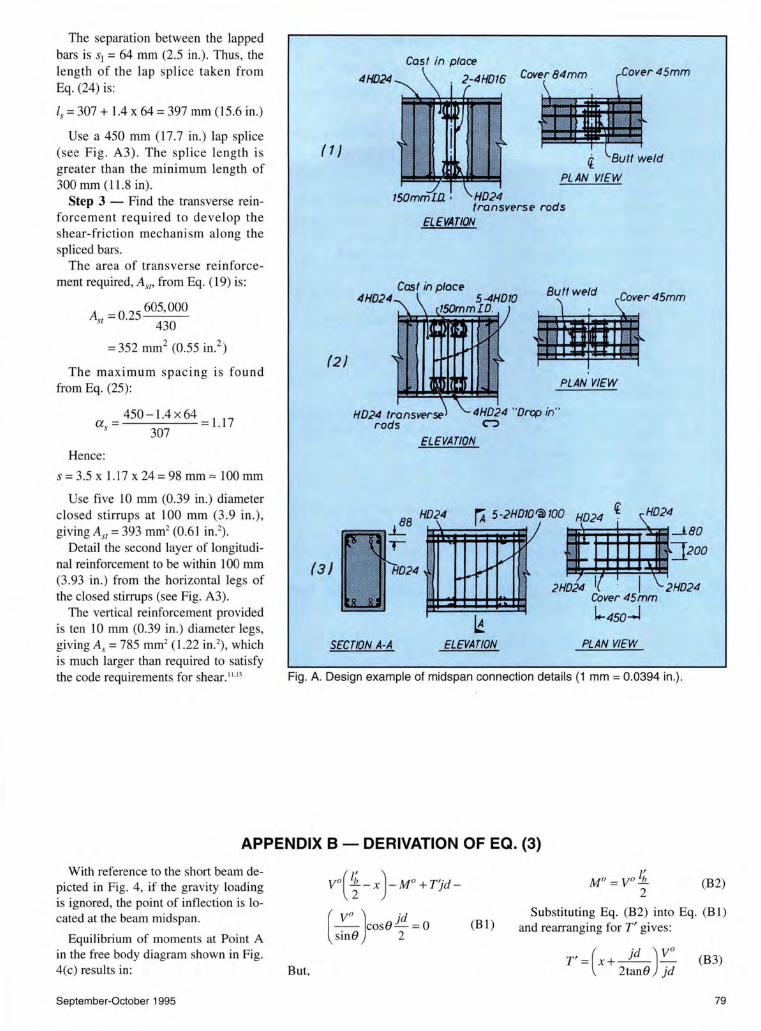
The separation between the lapped bars is s1 = 64 mm (2.5 in.) . Thus, the length of the lap splice taken from Eq. (24) is:
Is = 307 + 1.4 x 64 = 397 mm (15.6 in.)
Use a 450 mm (17.7 in.) lap splice (see Fig. A3). The splice length is greater than the minimum length of 300 mm (11.8 in).
Step 3 - Find the transverse reinforcement req uired to develop the shear-friction mechani sm along the spliced bars.
The area of transverse reinforcement required, Asr• from Eq. (19) is:
A = 0.25 605,000 st 430
= 352 mm2 (0.55 in? )
The maximum spac in g is fo und from Eq. (25):
a = 450- 1.4 x 64 = l.l 7 s 307
Hence:
s = 3.5 x 1.17 x 24 = 98 mm "" 100 mm
Use five 10 mm (0.39 in.) diameter closed stirrups at 100 mm (3 .9 in .), giving As,= 393 mm2 (0.61 in.2
) .
Detail the second layer of longitudinal reinforcement to be within 100 mm (3.93 in.) from the horizontal legs of the closed stirrups (see Fig. A3).
The vertical reinforcement provided is ten 10 mm (0.39 in.) diameter legs, giving As = 785 mm2 (1.22 in.2), which is much larger than required to satisfy the code requirements for shear.1
1.15
4H024
(1}
4HD24
(2)
(3}
SECTION A-A
HD24 transverse rods
ELEVATION
Cas f in place Butt weld
4HD24 "Drop in" CJ
PLAN VIEW
ELEVATION
\ JBO
~#~::J;oo 2HD24 I I 2HD24
!r'" ~
~~r
Cover45mm
~ l.-4so-J
ELEVATION PLAN VIEW
Fig. A. Design example of midspan connection details {1 mm = 0.0394 in .).
APPENDIX 8 - DERIVATION OF EQ. (3)
With reference to the short beam depicted in Fig. 4, if the gravity loading is ignored, the point of inflection is located at the beam midspan.
Equilibrium of moments at Point A in the free body diagram shown in Fig. 4(c) results in:
September-October 1995
But,
Vo( lb ) Mo T' 'd 2-x - + 1 -
( V
0 ) 'd -- coseL=o
sinO 2 (B 1)
(B2)
Substituting Eq. (B2) into Eq. (B I ) and rearranging forT' gives:
T' = (x + _l!!_) y o (B3) 2tane Jd
79

80
A,= effective friction surface
Ab = section area of reinforcing bar
A 51 = area of transverse reinforcing steel
bw = width of beam web
C0
= concrete cover to mam reinforcement
d = effective depth of beam
db= nominal diameter of reinforcing bar
D 0 = force in diagonal compression strut
fb = bearing stress
1: = concrete cylinder compressive strength
fy = yield strength of steel
hr = yield strength of transverse reinforcement
g = clear cover to extension of hook, measured in direction of plane of hook
hb = beam depth
j = internal beam lever arm expressed as fraction of d
lb = distance between column centerlines
APPENDIX C - NOTATION
l b = beam clear span
lc = length of midspan connection
ldh = development length of bar with standard hook
ls = required lap splice length
lsb = basic lap splice length
lsh = lapping length between hooked bars anchored in beam-to-column joint of System 1
lsp = provided lap splice length
M = bending moment acting at a section
M 0 = bending moment at overstrength of longitudinal reinforcement
n = number of drop-in double hooked bars transferring the force T"
sd = seating length of precast concrete beam of System 1
s1 = separation between pair of lapped bars
S0 = offset caused by separation of lapped bars
T, T', T" =theoretical tension force
in beam longitudinal reinforcement
Tb = individual bar force in a straight bar splice
r;, r;'= tensile capacity of lapped bars as detailed
Tv = additional tensile force in beam longitudinal reinforcement caused by diagonal tension cracking
T 0 = tension force of reinforcement at overstrength
V0 = shear force in beam, associated with development of flexural overstrength
x = horizontal distance in beam from point of inflection to given section
s = diameter of bend
1] = ratio between overlapping of hooks and bar diameter
8, 8', 8" = angle of inclination of a compression field of stresses
JlJ = coefficient of friction in shear-friction mechanism
r1 = average shear stress
ljJ = strength reduction factor
PCI JOURNAL
Recommended