Bulletin of the JSME
Journal of Advanced Mechanical Design, Systems, and ManufacturingVol.15, No.1, 2021
© 2021 The Japan Society of Mechanical Engineers[DOI: 10.1299/jamdsm.2021jamdsm0003]Paper No.20-00321
Design of a novel turning tool cooled by combining circulating
internal cooling with spray cooling for green cutting
Shengrong SHU*, Yu ZHANG*, Yiyun HE* and Han ZHANG*
Abstract
Cooling technology is vital in manufacturing industry, which can decrease cutting temperature, assist chip
removal and reduce or eliminate the generation of cutting liquid waste during metal cutting process. This paper
presents a novel turning tool cooled by combining circulating internal cooling with spray cooling, which can
cool the cutting tool tip from inside and outside of insert and assist blow chips away from cutting zone. Thermal-
fluid-solid coupling analysis using ANSYS Fluent is employed to investigate cooling performance of the
composite cooling turning tool. Optimization of the internal spray cooling structure is carried out by Taguchi
Method based CFD simulations and the optimal geometric parameters are picked out. The prototype of the novel
turning tool is fabricated through the integration of spray cooling technology into the previously developed
circulating internal cooling turning tool. The cooling effectiveness and practicality of the proposed novel turning
tool system are further examined and validated by cutting trials.
Keywords : Spray cooling, Circulating internal cooling, CFD simulation, Taguchi Method, Green machining
1. Introduction
Traditionally, a large amount of cooling liquid is poured to the cutting zone to cool the tool, workpiece and chips
during metal cutting process. Despite its role in reducing cutting temperature, improving the quality of workpiece and
assisting the chip removal, it brings a series of problems such as the harm to workers' health and pollution to environment
(Byrne, et al., 2003; Cetin, et al., 2011; Park, et al., 2010). So far, nations around the world have successively formulated
environmental regulations to restrict the use of cutting fluids. To overcome the negative effects of cutting fluid, many
researchers have conducted extensive study on green and harmless cooling cutting technology and related tooling design
(Dornfeld, et al., 2014; Vishal, et al., 2009; Vollertsen, et al., 2014).
A lot of cooling methods such as heat pipe cooling (Chiou, et al., 2007), internal cooling (Mia, 2017; Vicentin, et al.,
2011), or circulating internal cooling (Minton, et al., 2013; Isik, et al., 2017) and the corresponding cutting tools have
been applied to metal cutting. These newly designed tools with their respective cooling methods can achieve green or
near dry cutting. Among them, the circulating internal cooling tool performs prominently in reducing, predicting and
controlling the cutting temperature, and eliminating cutting fluid contamination in machining process (Shu, et al., 2013;
Wu, et al., 2018). The cooling liquid can flow along channels in internal cooling tool and get close to the cutting tool tip,
which quickly take away heat from cutting zone, further reducing the temperature at workpiece-tool-chip interfaces.
Moreover, the internal circulation of coolant avoids pollution to environment. However, it worth noting that it can’t cool
chips, workpiece and assist chip removal for that the cooling liquid only circulates inside the tool.
Spray cooling can compensate for the deficiency of circulating internal cooling in cooling and removing chips. It is
a near-dry cooling technique in cutting, which tiny liquid is mixed with compressed air to form fine droplets and spray
into cutting zone with airflow. The pressurized gas can help lifting up the chips and blowing them away from the cutting
zone (Nath, et al., 2017). Liquid droplets and film formed on the tool rake face and rotating workpiece can easily penetrate
into the cutting zone, which can lubricates and cools the tool-chip interface, thus improving the cutting tool life.
Compared with flood cooling, spray cooling shows similar machining performance on workpiece surface roughness and
*School of Mechatronics & Vehicle Engineering, East China Jiaotong University
808 Shuanggang East Street, Nanchang, Jiangxi Province, 330013, China
E-mail: [email protected]
Received: 29 June 2020; Revised: 23 September 2020; Accepted: 14 December 2020
1
2© 2021 The Japan Society of Mechanical Engineers[DOI: 10.1299/jamdsm.2021jamdsm0003]
Shu, Yu Zhang, He and Han Zhang, Journal of Advanced Mechanical Design, Systems, and Manufacturing, Vol.15, No.1 (2021)
residual stress, but longer tool life (Nath, et al., 2017; Jun, et al., 2008; Hoyne, et al., 2013). Cutting tools equipped with
an external spray nozzle can't obtain stable cooling performance for spraying direction are strongly controlled by operator.
However, cutting tools with inner channels and nozzle avoid the adjustment, therefore ensuring accuracy and repeatability
of the cooling process. Based on this, we present a novel turning tool which integrates the spray cooling and the
circulating internal cooling.
The cooling structure of the tool not only affects cooling performance but also mechanical property. For example, to
pursue a better cooling effect, a large coolant passage and groove are arranged in the tail and head of toolholder
respectively, which in turn reduces rigidity of the tool (Vicentin, et al., 2011). Another internally cooled tool was
comprised of a tool shank, cooling adaptor and hollow insert of 1mm wall thickness so that the coolant can get close to
the cutting zone (Carlo, et al., 2014). Such an insert has poor impact resistance and thus is prone to breakage in cutting
process. Above suggests that we should take not only good cooling performance, but also sufficient rigidity and strength
into account when design the composite cooling tool. Since the numerical simulation has been applied to the optimization
of spray parameters (Pereira, et al., 2017, Obikawa,et al., 2009) and the prediction of cutting temperature distribution
during turning (Sharma, et al., 2018, Pervaiz, et al., 2014), the cooling structure of the novel turning tool will also be
optimized by this method.
In this paper, a novel composite cooling turning tool is proposed by integrating spray cooling technology into the
previously developed circulating internal cooling tool (Shu, et al., 2013; Shu, 2014). Thermal-fluid-solid coupling
analyses by using ANSYS Fluent are conducted to study effectiveness of the new turning tool. CFD simulations are
carried out according to Taguchi orthogonal table, and the optimum structure design parameters of spray cooling are
obtained by signal-noise ratio analysis of the simulated cutting temperature results. Finally, the prototype of optimized
composite cooling turning tool is fabricated and tested by cutting trials.
2. Design and configuration of the novel turning tool
As shown in Fig.1, it is the simplified CAD model of the composite cooling turning tool. It is a reformation design
based on a standard turning tool which is composed of MSSNR2020K12 toolholder and SNMG120408 insert, adaptor
and clamp. Cooling structures are built into these parts, and cooling channels for internal cooling and spray cooling are
formed by assembling them together.
The internal cooling structure of the composite cooling turning tool is adapted from the previously developed
circulating internally cooled turning tool (Shu, et al., 2013; Shu, 2014). A standard tungsten carbide insert was sliced to
a thin insert with 1.8mm thick, which help cooling liquid take away heat quickly. There is an annular groove on top of
the support seat and some micro holes are located in the adapter and toolholder. Previously research demonstrated that a
thickness of 1.8mm of insert and a wall thickness 0.7mm towards flank face of support seat are sufficient to withstand
moderate mechanical loads (Shu, 2014). Thermal grease was used to seal interfaces between insert and support seat, and
O-ring seals were employed to avoid coolant leakage at flow channel interfaces between adaptor and toolholder. For
convenience, inlet and outlet of cooling liquid were arranged on the bottom of toolholder. As shown in Fig.1, red arrows
represent the flow of cooling liquid. The cooling liquid pumped from coolant supply system flows into inlet channel,
washes against beneath insert, flows out the tool and returns to coolant container of cooling system, which take away
heat in machining process.
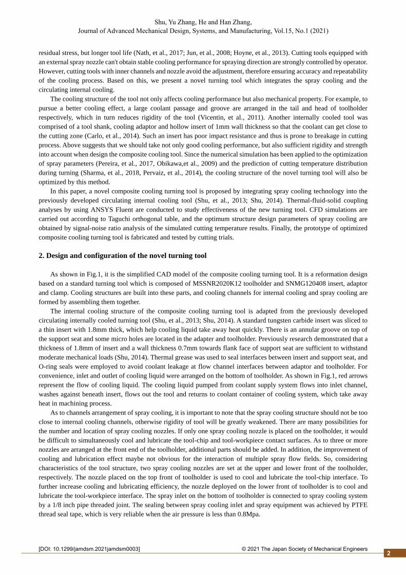
As to channels arrangement of spray cooling, it is important to note that the spray cooling structure should not be too
close to internal cooling channels, otherwise rigidity of tool will be greatly weakened. There are many possibilities for
the number and location of spray cooling nozzles. If only one spray cooling nozzle is placed on the toolholder, it would
be difficult to simultaneously cool and lubricate the tool-chip and tool-workpiece contact surfaces. As to three or more
nozzles are arranged at the front end of the toolholder, additional parts should be added. In addition, the improvement of
cooling and lubrication effect maybe not obvious for the interaction of multiple spray flow fields. So, considering
characteristics of the tool structure, two spray cooling nozzles are set at the upper and lower front of the toolholder,
respectively. The nozzle placed on the top front of toolholder is used to cool and lubricate the tool-chip interface. To
further increase cooling and lubricating efficiency, the nozzle deployed on the lower front of toolholder is to cool and
lubricate the tool-workpiece interface. The spray inlet on the bottom of toolholder is connected to spray cooling system
by a 1/8 inch pipe threaded joint. The sealing between spray cooling inlet and spray equipment was achieved by PTFE
thread seal tape, which is very reliable when the air pressure is less than 0.8Mpa.
2
2© 2021 The Japan Society of Mechanical Engineers[DOI: 10.1299/jamdsm.2021jamdsm0003]
Shu, Yu Zhang, He and Han Zhang, Journal of Advanced Mechanical Design, Systems, and Manufacturing, Vol.15, No.1 (2021)
Because cooling structures inside the turning tool will weaken rigidity and strength, the dimensions of spray cooling
structure should be reasonably designed to ensure mechanical properties of the turning tool and maximize cooling
efficiency.
Fig. 1 Simplified model of the composite cooling turning tool Fig. 2 Geometric parameter of spray cooling
3. Taguchi's experimental design
The diameter of spray outlet has important influence on air flow rate, and also affects size, velocity and volume
fraction of droplets (Wang, et al., 2019). The distance between spray nozzle and cooling surface can significantly affect
spray field coverage, liquid film velocity and thickness (Maruda, et al., 2016). Therefore, cooling structure dimensions
of the composite cooling turning tool will affect heat transfer among compressed air, coolant droplets and cutting zone.
In order to improve cooling efficiency, the geometric parameters of spray cooling structure should be optimized.
As shown in Fig. 2, the important geometric variables include the upper spray outlet diameter (UOD), the lower
spray outlet diameter (LOD), the distance between upper spray outlet and cutting tool tip (First distance, FD), and the
distance between lower spray outlet and cutting tool tip (Second distance, SD). Taguchi method is used to investigate the
influence of above four factors and optimize spray cooling structure parameters of the turning tool. It utilizes orthogonal
arrays to minimize the time and cost of experiments, and the optimal combination of factors and levels can be obtained
by signal-noise ratio analysis of the simulated cutting temperature.
Table 1 Range of the four design parameters
Parameters levels
1 2 3
A UOD (mm) 1.0 2.0 3.0
B LOD (mm) 1.0 2.0 3.0
C FD (mm) 16.8 21.0 25.2
D SD (mm) 11.6 14.6 17.6
Table 2 L9 orthogonal array
Experiment upper spray outlet diameter
A
lower spray outlet diameter
B
First distance
C
Second distance
D Combination
1 1 1 1 1 A1B1C1D1
2 1 2 2 2 A1B2C2D2
3 1 3 3 3 A1B3C3D3
4 2 1 2 3 A2B1C2D3
5 2 2 3 1 A2B2C3D1
6 2 3 1 2 A2B3C1D2
7 3 1 3 2 A3B1C3D2
8 3 2 1 3 A3B2C1D3
9 3 3 2 1 A3B3C2D1
3
2© 2021 The Japan Society of Mechanical Engineers[DOI: 10.1299/jamdsm.2021jamdsm0003]
Shu, Yu Zhang, He and Han Zhang, Journal of Advanced Mechanical Design, Systems, and Manufacturing, Vol.15, No.1 (2021)
Since channels of spray cooling are located at the front end of toolholder, the four design parameters are limited
within a certain range. Table 1 shows the four parameters and three levels of the novel turning tool. Table 2 presents
Taguchi's Table L9(34) employed in this procedure. In order to ensure that liquid droplets are sprayed toward cutting zone,
the upper nozzle points to tool tip and the angle between the axis of lower nozzle and tool rake face should be unchanged
for each design scheme.
After steady-state analysis for each design scheme in Table 2, the cooling performance is evaluated by area-weighted
average temperature of tool-chip interface. The lower the area-weighted average temperature of tool-chip interface, the
better cooling efficiency of the tool. Through statistical analysis performed on area-weighted average temperature of
tool-chip interface, we can find the optimal parameters and levels combination.
4. CFD simulation
4.1 Simulation setup
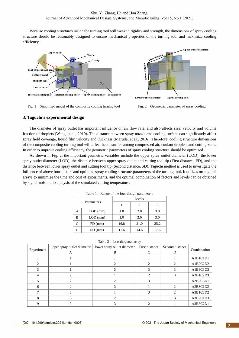
Thermal-fluid-solid coupling simulation analysis by using ANSYS Fluent are conducted to investigate cooling
performance of the composite cooling turning tool. Fig.3 shows the geometric model of CFD simulation. It comprises
the simplified turning tool, workpiece, a small piece of curved chip and fluid domain. The fluid zone can simulates flow
of air and droplets and is large enough to capture flow characteristic around cutting zone with a volume of 95mm × 80mm
× 70mm.
Fig. 3 Schematic view of the geometric model of simulation
Table 3 Simulation parameters
Variable Value Variable Value
Density of insert (kg/m3) 14900 Air/Water temperature (℃) 20
Elastic modulus of insert (MPa) 5.2E5 Specific heat of water (J/kg·K) 4182
Poisson's ratio of insert 0.4 Viscosity of water (kg/m·s) 0.001
Thermal conductivity of insert (W/m∙K) 52.3 Density of water (kg/m3) 998.2
Specific heat of insert (J/kg∙K) 302 Thermal conductivity of water (W/m·K) 0.6
Tool-chip contact area (ω mm×Lc mm) 0.5×1.5 Inlet velocity of internal cooling (m/s) 1
Heat flux on contact area (W/mm2) 10 Inlet pressure of spray cooling (MPa) 0.3
Since volume fraction of coolant droplet is much smaller than air, the discrete phase model (DPM) is selected to
simulate particle trajectories and properties within fluid domain. Considering entrainment during spraying, and
disturbance caused by fluid impingement on the surfaces of tool and workpiece, realizable k-ε turbulence model is used
in this simulation. The species transport model is activated in order to model coolant droplets boiling and vaporization.
The Wall-film model is applied to the simulation of liquid droplets colliding with walls thus forming thin films, splashing
and vaporization.
The mesh quantity and quality of simulation model will affect time and accuracy of calculation. In order to improve
computation efficiency under ensuring accuracy, grids are divided densely around the cutting zone and relatively coarse
4
2© 2021 The Japan Society of Mechanical Engineers[DOI: 10.1299/jamdsm.2021jamdsm0003]
Shu, Yu Zhang, He and Han Zhang, Journal of Advanced Mechanical Design, Systems, and Manufacturing, Vol.15, No.1 (2021)
in other positions when meshing. Mesh convergence tests have been carried out by varying element sizes to get optimum
element sizes for different parts of each design scheme simulation model. Because the purified water has a good heat
transfer performance, and it is readily available and harmless to environment and human, we choose the purified water
as the cooling fluid for internal cooling and spray cooling in this study. For all the simulations, the tool-chip contact area
is 0.5mm×1.5mm, the heat flow rate conducted into the cutting insert is 10W/mm2, the coolant inlet velocity of internal
cooling is 1m/s and its temperature is 20°C, the coolant flow rate of spray cooling is 50mL/h and its temperature is 20°C.
Table 3 lists most of input values of thermal-fluid-solid coupling simulations for the composite cooling turning tool.
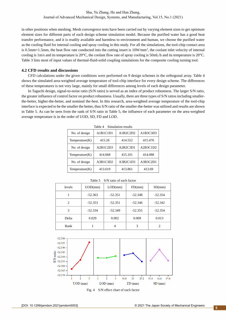
4.2 CFD results and discussions
CFD calculations under the given conditions were performed on 9 design schemes in the orthogonal array. Table 4
shows the simulated area-weighted average temperature of tool-chip interface for every design scheme. The differences
of these temperatures is not very large, mainly for small differences among levels of each design parameter.
In Taguchi design, signal-to-noise ratio (S/N ratio) is served as an index of product robustness. The larger S/N ratio,
the greater influence of control factor on product robustness. Usually, there are three types of S/N ratios including smaller-
the-better, higher-the-better, and nominal the-best. In this research, area-weighted average temperature of the tool-chip
interface is expected to be the smaller the better, thus S/N ratio of the smaller-the-better was utilized and results are shown
in Table 5. As can be seen from the rank of S/N ratio in Table 5, the influence of each parameter on the area-weighted
average temperature is in the order of UOD, SD, FD and LOD.
Table 4 Simulation results
No. of design A1B1C1D1 A1B2C2D2 A1B3C3D3
Temperature(K) 415.26 414.552 415.476
No. of design A2B1C2D3 A2B2C3D1 A2B3C1D2
Temperature(K) 414.668 415.101 414.088
No. of design A3B1C3D2 A3B2C1D3 A3B3C2D1
Temperature(K) 413.619 413.861 413.69
Table 5 S/N ratio of each factor
levels UOD(mm) LOD(mm) FD(mm) SD(mm)
1 -52.363 -52.351 -52.348 -52.354
2 -52.353 -52.351 -52.346 -52.342
3 -52.334 -52.349 -52.355 -52.354
Delta 0.029 0.002 0.009 0.013
Rank 1 4 3 2
Fig. 4 S/N effect chart of each factor
5
2© 2021 The Japan Society of Mechanical Engineers[DOI: 10.1299/jamdsm.2021jamdsm0003]
Shu, Yu Zhang, He and Han Zhang, Journal of Advanced Mechanical Design, Systems, and Manufacturing, Vol.15, No.1 (2021)
In order to analyze the influence of four design parameters on tool-chip interface temperature intuitively, the S/N
main effect map of each factor is plotted according to Table 5 and shown in Fig. 4. As can be seen from Fig. 4, for UOD,
cooling effect becomes better with the increase of nozzle diameter. This may be primarily because the larger outlet
diameter, the larger flow rate of droplets when inlet air pressure is constant, so that more droplets enter the cutting zone
and take heat away. Similarly, the larger LOD, the more pronounced cooling effect. FD and SD have similar effect on
tool-chip interface temperature. The temperature of tool-chip contact area doesn’t decrease monotonously as the two
distances decrease, while the medium distances minimize the temperature. This may be due to most of droplets splash
and rebound after impacting with wall surface when the two distances are small, while droplet’s momentum is not big
when the distances are larger.
Based on above results, the optimal parameters levels combination is A3B3C2D2, in which the UOD = 3.0mm, the
LOD = 3.0mm, the FD = 21.0 mm, the SD = 14.6 mm. In the simulation results of each design in Table 3, the parameters
and levels combination with minimum area-weighted average temperature is A3B1C3D2. It is different from the optimal
levels combination, so further verification is needed.
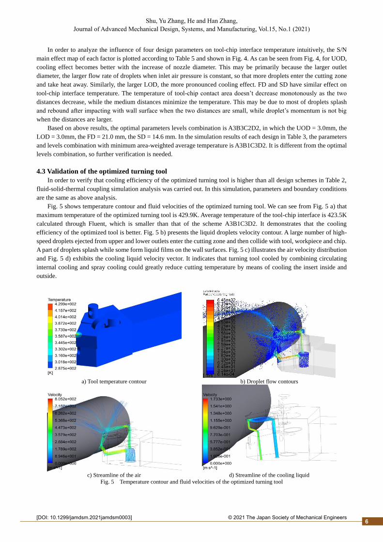
4.3 Validation of the optimized turning tool
In order to verify that cooling efficiency of the optimized turning tool is higher than all design schemes in Table 2,
fluid-solid-thermal coupling simulation analysis was carried out. In this simulation, parameters and boundary conditions
are the same as above analysis.
Fig. 5 shows temperature contour and fluid velocities of the optimized turning tool. We can see from Fig. 5 a) that
maximum temperature of the optimized turning tool is 429.9K. Average temperature of the tool-chip interface is 423.5K
calculated through Fluent, which is smaller than that of the scheme A3B1C3D2. It demonstrates that the cooling
efficiency of the optimized tool is better. Fig. 5 b) presents the liquid droplets velocity contour. A large number of high-
speed droplets ejected from upper and lower outlets enter the cutting zone and then collide with tool, workpiece and chip.
A part of droplets splash while some form liquid films on the wall surfaces. Fig. 5 c) illustrates the air velocity distribution
and Fig. 5 d) exhibits the cooling liquid velocity vector. It indicates that turning tool cooled by combining circulating
internal cooling and spray cooling could greatly reduce cutting temperature by means of cooling the insert inside and
outside.
a) Tool temperature contour b) Droplet flow contours
c) Streamline of the air
d) Streamline of the cooling liquid
Fig. 5 Temperature contour and fluid velocities of the optimized turning tool
6
2© 2021 The Japan Society of Mechanical Engineers[DOI: 10.1299/jamdsm.2021jamdsm0003]
Shu, Yu Zhang, He and Han Zhang, Journal of Advanced Mechanical Design, Systems, and Manufacturing, Vol.15, No.1 (2021)
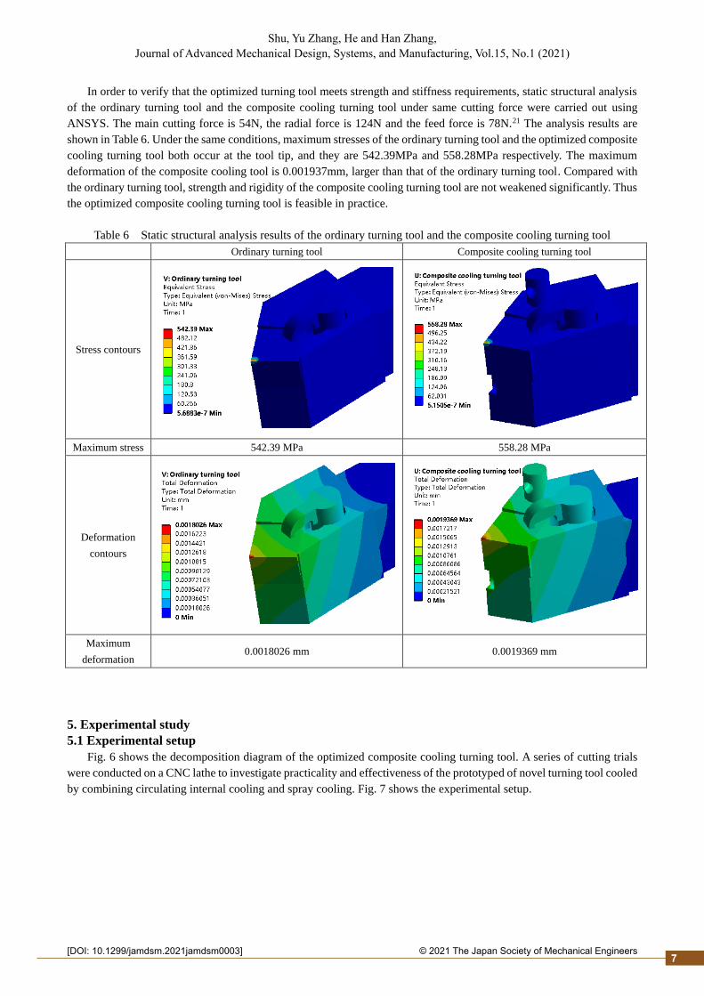
In order to verify that the optimized turning tool meets strength and stiffness requirements, static structural analysis
of the ordinary turning tool and the composite cooling turning tool under same cutting force were carried out using
ANSYS. The main cutting force is 54N, the radial force is 124N and the feed force is 78N.21 The analysis results are
shown in Table 6. Under the same conditions, maximum stresses of the ordinary turning tool and the optimized composite
cooling turning tool both occur at the tool tip, and they are 542.39MPa and 558.28MPa respectively. The maximum
deformation of the composite cooling tool is 0.001937mm, larger than that of the ordinary turning tool. Compared with
the ordinary turning tool, strength and rigidity of the composite cooling turning tool are not weakened significantly. Thus
the optimized composite cooling turning tool is feasible in practice.
Table 6 Static structural analysis results of the ordinary turning tool and the composite cooling turning tool
Ordinary turning tool Composite cooling turning tool
Stress contours
Maximum stress 542.39 MPa 558.28 MPa
Deformation
contours
Maximum
deformation 0.0018026 mm 0.0019369 mm
5. Experimental study
5.1 Experimental setup
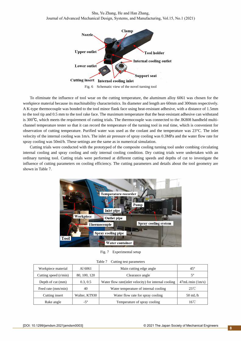
Fig. 6 shows the decomposition diagram of the optimized composite cooling turning tool. A series of cutting trials
were conducted on a CNC lathe to investigate practicality and effectiveness of the prototyped of novel turning tool cooled
by combining circulating internal cooling and spray cooling. Fig. 7 shows the experimental setup.
7
2© 2021 The Japan Society of Mechanical Engineers[DOI: 10.1299/jamdsm.2021jamdsm0003]
Shu, Yu Zhang, He and Han Zhang, Journal of Advanced Mechanical Design, Systems, and Manufacturing, Vol.15, No.1 (2021)
Fig. 6 Schematic view of the novel turning tool
To eliminate the influence of tool wear on the cutting temperature, the aluminum alloy 6061 was chosen for the
workpiece material because its machinability characteristics. Its diameter and length are 60mm and 300mm respectively.
A K-type thermocouple was bonded to the tool minor flank face using heat-resistant adhesive, with a distance of 1.5mm
to the tool tip and 0.5 mm to the tool rake face. The maximum temperature that the heat-resistant adhesive can withstand
is 300℃, which meets the requirement of cutting trials. The thermocouple was connected to the JK808 handheld multi-
channel temperature tester so that it can record the temperature of the turning tool in real time, which is convenient for
observation of cutting temperature. Purified water was used as the coolant and the temperature was 23°C. The inlet
velocity of the internal cooling was 1m/s. The inlet air pressure of spray cooling was 0.3MPa and the water flow rate for
spray cooling was 50ml/h. These settings are the same as in numerical simulation.
Cutting trials were conducted with the prototyped of the composite cooling turning tool under combing circulating
internal cooling and spray cooling and only internal cooling condition. Dry cutting trials were undertaken with an
ordinary turning tool. Cutting trials were performed at different cutting speeds and depths of cut to investigate the
influence of cutting parameters on cooling efficiency. The cutting parameters and details about the tool geometry are
shown in Table 7.
Fig. 7 Experimental setup
Table 7 Cutting test parameters
Workpiece material Al 6061 Main cutting edge angle 45°
Cutting speed (r/min) 80, 100, 120 Clearance angle 5°
Depth of cut (mm) 0.3, 0.5 Water flow rate(inlet velocity) for internal cooling 47mL/min (1m/s)
Feed rate (mm/min) 40 Water temperature of internal cooling 23℃
Cutting insert Walter, KT930 Water flow rate for spray cooling 50 mL/h
Rake angle -5° Temperature of spray cooling 16℃
8
2© 2021 The Japan Society of Mechanical Engineers[DOI: 10.1299/jamdsm.2021jamdsm0003]
Shu, Yu Zhang, He and Han Zhang, Journal of Advanced Mechanical Design, Systems, and Manufacturing, Vol.15, No.1 (2021)
5.2 Results and discussions
Table 8 lists steady-state temperatures of sampling points of the ordinary turning tool and the composite cooling
turning tool under various cutting conditions. It demonstrates that the composite cooling turning tool can effectively
decrease cutting temperature. Steady-state temperature of internal cooling turning tool is just a little lower than that of
the ordinary turning tool, while the composite cooling turning tool is nearly half. In addition, cooling performance of
both internal cooling and composite cooling is getting better with cutting speed increases.
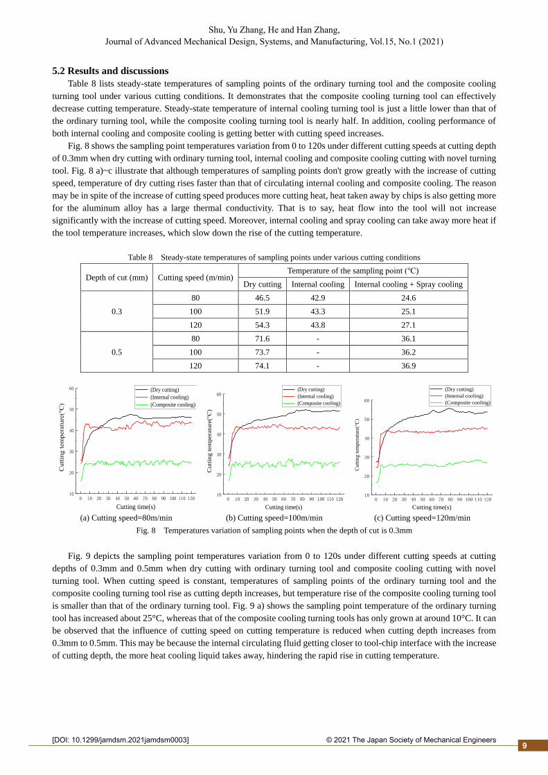
Fig. 8 shows the sampling point temperatures variation from 0 to 120s under different cutting speeds at cutting depth
of 0.3mm when dry cutting with ordinary turning tool, internal cooling and composite cooling cutting with novel turning
tool. Fig. 8 a)~c illustrate that although temperatures of sampling points don't grow greatly with the increase of cutting
speed, temperature of dry cutting rises faster than that of circulating internal cooling and composite cooling. The reason
may be in spite of the increase of cutting speed produces more cutting heat, heat taken away by chips is also getting more
for the aluminum alloy has a large thermal conductivity. That is to say, heat flow into the tool will not increase
significantly with the increase of cutting speed. Moreover, internal cooling and spray cooling can take away more heat if
the tool temperature increases, which slow down the rise of the cutting temperature.
Table 8 Steady-state temperatures of sampling points under various cutting conditions
Depth of cut (mm) Cutting speed (m/min) Temperature of the sampling point (℃)
Dry cutting Internal cooling Internal cooling + Spray cooling
0.3
80 46.5 42.9 24.6
100 51.9 43.3 25.1
120 54.3 43.8 27.1
0.5
80 71.6 - 36.1
100 73.7 - 36.2
120 74.1 - 36.9
(a) Cutting speed=80m/min (b) Cutting speed=100m/min (c) Cutting speed=120m/min
Fig. 8 Temperatures variation of sampling points when the depth of cut is 0.3mm
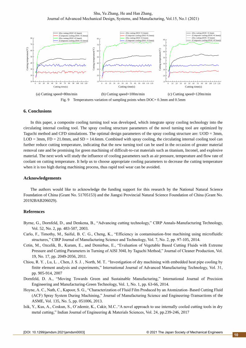
Fig. 9 depicts the sampling point temperatures variation from 0 to 120s under different cutting speeds at cutting
depths of 0.3mm and 0.5mm when dry cutting with ordinary turning tool and composite cooling cutting with novel
turning tool. When cutting speed is constant, temperatures of sampling points of the ordinary turning tool and the
composite cooling turning tool rise as cutting depth increases, but temperature rise of the composite cooling turning tool
is smaller than that of the ordinary turning tool. Fig. 9 a) shows the sampling point temperature of the ordinary turning
tool has increased about 25°C, whereas that of the composite cooling turning tools has only grown at around 10°C. It can
be observed that the influence of cutting speed on cutting temperature is reduced when cutting depth increases from
0.3mm to 0.5mm. This may be because the internal circulating fluid getting closer to tool-chip interface with the increase
of cutting depth, the more heat cooling liquid takes away, hindering the rapid rise in cutting temperature.
0 10 20 30 40 50 60 70 80 90 100 110 12010
20
30
40
50
60
Cu
ttin
g t
em
pera
ture
(℃)
Cutting time(s)
(Dry cutting)
(Internal cooling)
(Composite cooling)
0 10 20 30 40 50 60 70 80 90 100 110 12010
20
30
40
50
60
Cu
ttin
g t
em
pera
ture
(℃)
Cutting time(s)
(Dry cutting)
(Internal cooling)
(Composite cooling)
0 10 20 30 40 50 60 70 80 90 100 110 12010
20
30
40
50
60
Cutt
ing t
emper
ature
(℃)
Cutting time(s)
(Dry cutting)
(Internal cooling)
(Composite cooling)
9
2© 2021 The Japan Society of Mechanical Engineers[DOI: 10.1299/jamdsm.2021jamdsm0003]
Shu, Yu Zhang, He and Han Zhang, Journal of Advanced Mechanical Design, Systems, and Manufacturing, Vol.15, No.1 (2021)
(a) Cutting speed=80m/min (b) Cutting speed=100m/min (c) Cutting speed=120m/min
Fig. 9 Temperatures variation of sampling points when DOC= 0.3mm and 0.5mm
6. Conclusions
In this paper, a composite cooling turning tool was developed, which integrate spray cooling technology into the
circulating internal cooling tool. The spray cooling structure parameters of the novel turning tool are optimized by
Taguchi method and CFD simulations. The optimal design parameters of the spray cooling structure are: UOD = 3mm,
LOD = 3mm, FD = 21.0mm, and SD = 14.6mm. Combined with spray cooling, the circulating internal cooling tool can
further reduce cutting temperature, indicating that the new turning tool can be used in the occasion of greater material
removal rate and be promising for green machining of difficult-to-cut materials such as titanium, Inconel, and explosive
material. The next work will study the influence of cooling parameters such as air pressure, temperature and flow rate of
coolant on cutting temperature. It help us to choose appropriate cooling parameters to decrease the cutting temperature
when it is too high during machining process, thus rapid tool wear can be avoided.
Acknowledgements
The authors would like to acknowledge the funding support for this research by the National Natural Science
Foundation of China (Grant No. 51705153) and the Jiangxi Provincial Natural Science Foundation of China (Grant No.
20192BAB206029).
References
Byrne, G., Dornfeld, D., and Denkena, B., “Advancing cutting technology,” CIRP Annals-Manufacturing Technology,
Vol. 52, No. 2, pp. 483-507, 2003.
Carlo, F., Timothy, M., Saiful, B. C. G., Cheng, K., “Efficiency in contamination-free machining using microfluidic
structures,” CIRP Journal of Manufacturing Science and Technology, Vol. 7, No. 2, pp. 97-105, 2014.
Cetin, M., Ozcelik, B., Kuram, E., and Demirbas, E., “Evaluation of Vegetable Based Cutting Fluids with Extreme
Pressure and Cutting Parameters in Turning of AISI 304L by Taguchi Method,” Journal of Cleaner Production, Vol.
19, No. 17, pp. 2049-2056, 2011.
Chiou, R. Y. , Lu, L. , Chen, J. S. J. , North, M. T.. “Investigation of dry machining with embedded heat pipe cooling by
finite element analysis and experiments,” International Journal of Advanced Manufacturing Technology, Vol. 31,
pp. 905-914, 2007
Dornfeld, D. A., “Moving Towards Green and Sustainable Manufacturing,” International Journal of Precision
Engineering and Manufacturing-Green Technology, Vol. 1, No. 1, pp. 63-66, 2014.
Hoyne, A. C., Nath, C., Kapoor, S. G., “Characterization of Fluid Film Produced by an Atomization–Based Cutting Fluid
(ACF) Spray System During Machining,” Journal of Manufacturing Science and Engineering-Transactions of the
ASME, Vol. 135, No. 5, pp. 051006, 2013.
Isik, Y., Kus, A., Coskun, S., O¨zdemir, K., Cakir, M.C..“A novel approach to use internally cooled cutting tools in dry
metal cutting,” Indian Journal of Engineering & Materials Sciences, Vol. 24, pp.239-246, 2017
0 10 20 30 40 50 60 70 80 90 100 110 12010
20
30
40
50
60
70
80
Cutt
ing t
emper
ature
(℃)
Cutting time(s)
(Dry cutting (DOC=0.3mm))
(Composite cooling (DOC=0.3mm))
(Dry cutting (DOC=0.5mm))
(Composite cooling (DOC=0.5mm))
0 10 20 30 40 50 60 70 80 90 100 110 12010
20
30
40
50
60
70
80
Cu
ttin
g t
emp
erat
ure
(℃)
Cutting time(s)
(Dry cutting (DOC=0.3mm))
(Composite cooling (DOC=0.3mm))
(Dry cutting (DOC=0.5mm))
(Composite cooling (DOC=0.5mm))
0 10 20 30 40 50 60 70 80 90 100 110 12010
20
30
40
50
60
70
80
Cutt
ing t
emper
ature
(℃)
Cutting time(s)
(Dry cutting (DOC=0.3mm)
(Composite cooling (DOC=0.3mm))
(Dry cutting (DOC=0.5mm))
(Composite cooling (DOC=0.5mm))
10
2© 2021 The Japan Society of Mechanical Engineers[DOI: 10.1299/jamdsm.2021jamdsm0003]
Shu, Yu Zhang, He and Han Zhang, Journal of Advanced Mechanical Design, Systems, and Manufacturing, Vol.15, No.1 (2021)
Jun, M. B. G., Joshi, S. S., DeVor, R. E., Kapoor, S. G., “An Experimental Evaluation of an Atomization-Based Cutting
Fluid Application System for Micromachining,” Journal of Manufacturing Science and Engineering-Transactions
of the ASME, Vol. 130, No. 3, pp. 283-290, 2008.
Maruda, R. W., Krolczyk, G. M., Feldshtein, E., et al. “A study on droplets sizes, their distribution and heat exchange for
minimum quantity cooling lubrication(MQCL),” International Journal of Machine Tools and Manufacture, Vol. 100,
pp.81-92, 2016.
Mia, M., “Multi-response optimization of end milling parameters under through-tool cryogenic cooling condition,”
Measurement, Vol. 111, pp. 134-145, 2017.
Minton, T. , Ghani, S. , Sammler, F. et al. “Temperature of internally-cooled diamond-coated tools for dry-cutting
titanium,” International Journal of Machine Tools and Manufacture, Vol. 75, pp. 27-35, 2013.
Nath, C., Kapoor, S. G., Srivastava, A. K., “Finish turning of Ti-6Al-4V with the atomization-based cutting fluid (ACF)
spray system,” Journal of Manufacturing Processes, Vol. 28, No. 3, pp. 464-471, 2017.
Obikawa, T. , Asano, Y. , Kamata, Y. “Computer fluid dynamics analysis for efficient spraying of oil mist in finish-turning
of Inconel,” International Journal of Machine Tools and Manufacture, Vol. 49, pp.971-978, 2009.
Park, K., Olortegui-Yume, J., Yoon, M., and Kwon, P., “A Study on Droplets and Their Distribution for Minimum
Quantity Lubrication (MQL),” International Journal of Machine Tools and Manufacture, Vol. 50, No. 9, pp. 824-
833, 2010.
Pereira, O., Rodriguez, A., Barreiro, J., Fernandez-Abia, A. I., Lopez de Lacalle, L. N., “Nozzle design for combined use
of MQL and cryogenic gas in machining,” International Journal of Precision Engineering and Manufacturing-Green
Technology, Vol. 4, No. 1, pp. 87-95, 2017.
Pervaiz, S., Deiab, I., Wahba, E., Wahba, E., Rashid, A., Nicolescu, M., “A numerical and experimental study to
investigate convective heat transfer and associated cutting temperature distribution in single point turning,”
International Journal of Advanced Manufacturing Technology, Vol. 94, No. 1-4, pp. 897-910, 2018.
Sharma, A. K., Tiwari, A. K., Dixit, A. R., “Prediction of temperature distribution over cutting tool with alumina-
MWCNT hybrid nanofluid using computational fluid dynamics (CFD) analysis,” International Journal of Advanced
Manufacturing Technology, Vol. 97, No. 1-4, pp. 427-439, 2018.
Shu, S. R., “Design and analysis of the internally cooled smart turning tool and experimental study,” Ph.D. thesis, Harbin
Institute of Technology, Harbin, 2014 (in Chinese).
Shu, S. R., Cheng, K., Ding, H., and Chen, S., “An Innovative Method to Measure the Cutting Temperature in Process
by Using an Internally Cooled Smart Cutting Tool,” Journal of Manufacturing Science and Engineering, Vol. 135,
Paper No. 61018, 2013.
Vicentin, G. C., Sanchez, L. E. A., Scalon, V. L., et al. “A sustainable alternative for cooling the machining processes
using a refrigerant fluid in recirculation inside the toolholder,” Clean Technologies and Environmental Policy, Vol.
13, No. 6, pp. 831-840, 2011.
Vishal, S., Sharmam, D. N. M., “Cooling techniques for improved productivity in turning,” International Journal of
Machine Tools and Manufacture, Vol. 49, pp. 435-453, 2009.
Vollertsen, F. and Schmidt, F., “Dry Metal Forming: Definition, Chances and Challenges,” International Journal of
Precision Engineering and Manufacturing-Green Technology, Vol. 1, No. 1, pp. 59-62, 2014.
Wang, P. F., Tan, X. H., Liu, R. H., Wang, H. Q., Li, Y. J., et al. “Effect of structural parameters on atomization
characteristics and dust reduction performance of internal-mixing air-assisted atomizer nozzle,” Process Safety and
Environmental Protection, Vol. 128, pp. 316-328, 2019.
Wu, T., Li, T., Ding, X., Chen, H., and Wang, L., “Design of a Modular Green Closed Internal Cooling Turning Tool for
Applications,” International Journal of Precision Engineering and Manufacturing-Green Technology, Vol. 5, No. 2,
pp. 211-217, 2018.
11
Recommended


![Combining surgery and immunotherapy: turning an ... · correlating with the degree of surgical trauma [3]. Des-pite these early promising findings, limited mechanistic advances have](https://img.pdfslide.us/doc/110x75/5f569505fe9968497d5a4c7e/combining-surgery-and-immunotherapy-turning-an-correlating-with-the-degree.jpg)