,
DESIGl'1ING NEW MINIMUM Q UANTfTY OF LUBRICATION (MQL) APPLICATOR FOR MILLI NG
SteveD Joel Anak Total
Bachelor of Engineering with Honours (Mechanical and Manufacturing Engineering)
2017
UNIVE RSITI MALAYSIA SARAWAK
Grade: _ ____
Please tick <v) Final Year Project Report gMasters
PhD D
DECLARATION OF ORIGINAL WORK
This declaration is made on the .. :2 Y.day of Ju iq i 20 l2.
Student's Declaration:
TSTEVEN JOEL ANAK TOTAL, (44260) FROM DEPARTMENT OF MECHANICAL AND MANUFACTUTING ENGINEERlNG OF FACULTI ENGINEERING hereby declare that the work entitled DESIGNING NEW MINIMUM QUANTITY OF LUBRICATION(MQL) APPLICATOR FOR MILLING is my original work. I have not copied from any other students' work or from any other sources except where due reference or acknowledgement is made explicitly in the text, nor has any part been wntten for me by another person.
Date submitted STEVEN JOEL .\NAK TOTAL (44260)
Supervisor's Declaration:
I Dr ABANGMOHD. NIZAM BIN ABANG KAMARUDDIN hereby certifies that the work entitled DESIGNING NEW MINIMUM QUANTITY LUBRICATION (MQL) .\PPLTCATOR FOR lVIll,LlNG was prepared by the above named student, and was submitted to the "FACULTY' as a * partiaJJfull fuUillment for the conferment of BACHELOR OF MECHANICAL AND MANUF "CTURf G ENGINEERING, and the aforementioned work, to the best of my knowledge, is the said student's work.
Received for examination by: Date: (Dr. ABANG MODH NIZAM B N ANG KAlV1ARUDDIN)
I declare th at P rojectlThesis is classifIed as (please tick ("Jj) .
D CONFIDENTIAL (Con tains confidential Inform ation unde r the Official Secret Act 1972)* DRESTRICTED (Con ta ins restricted inlormation as specifi ed by the organisa tion where
research was done)* !ZlOPEN ACCESS
Validation of Proj ect/Thesis
I therefore duly affirm with free consent and willingly declare that th is said Proje.c ttrhesis shall he placed officially in the Centre for Academic Information Services with the ab iding interest and rights as follows:
• This ProJec t/ lbesis is th e sole lega l property of Univers it i Malays ia Sa rawa k (U NJM AS). • The Centre for Academic Information Serv ices has the la.-ful right to make COI"es for the
purpose of academic a nd research only a nd not for other purpose .
• The Cent re for Academic Information Serv ices has the law ful right to digitalise the content for th e Loca l Coo tent Database.
• The Centre for Academic Information Services has the law ful right to make copies of the ProjeCllThesis for academic exchange between High er Learning Institute.
• No dispute or any cla im shall arise from the student itself neither third party on this ProjectlThesis once it becomes the sole property of UNTMAS.
• Thi s ProjecLlThesis or any matcrial. data . and information rclatcd to it shall not be di stributed, published or clisclosed to any party by the studen t excep t with UNJI,I AS permission.
Studen t signature __~_--"'--='-___ _ S upervisor signature: ~ Current Address: Department of Mechanical and Manulacturing EngUleering, Faculty of Engineering, University Malay'sia Sarawak 94300 Kota Sam,;rahan. Sarawak
Notes: * If the ProjeeL/rhesis is CONFIDENTIAL or RESTRICTED, p lease attach together as annexure a lette r from the orga nisation with the period and reasons of confidenti ahty and resLriction.
[The mstrumcnt is du ly p",pared by The Centre for Academ ic Jnlormation Serv ices]
APPROVAL SHEET
Th,s project report which entitled "Design new Minimum Quantity of Lubrication (MQL)
Applicator for Milhng" was prepared by Steven Joel anak Total (44260) is hereby read and
approved by:
Dr Abang M d. Nizam bin Abang Kamaruddin Date
Project SupervIsor
DESIGNING NEW MINIUMUM QUANTITY OF LUB R ICAT ION (MQL)
APPLICATOR FOR M ILLING
STEVEN JOEL ANAK TOTAL
Thes Is is submitted to
Faculty of Engmeenng, Un ivers itJ Malays ia Sa rawak
Tn Partia l Fulfilmen t of the Requirements
For the Degree of Bachelor of Engmeering
With Honours (Mechanica l and Manufac turing Englneenng) 2017
Dedicated to my beloved parents, frien d and family for the never ending support ,
encouragements and motivation.
ACKNOWLEDGEMENTS
Firstly, I li ke to thank The Almighty God Jesus Chri st fo r Hi s Blessing and wi lling for the
comple tion this thesi s res earch. I wo uld like to address my highest ap preciation to
University Malaysia Sa ra wak and the engineering fac ulty department of Mechanical and
Manufactu rin g Eng ineering for providing the faci lity durin g the course of this research. 1
would like to express my heartfelt gratitude to my supervisor, Dr. Abang M.ohd Nizam bin
Abang Kamaruddin for his endless support and encouragements durin g ongoing of this
research . My deepest thanks also for the faculty technicians for their guidance and suppon
during experimentation and fabrication of thiS project. In alphabetical order they are· Mr
lreman Bolhassan, Mr Mohd Fa irudy Mohd. Jamil , and l\1r Sabariman Bakar l would also
like to express thanks to fello w friends for the constant support and encouragements
especia ll y Ridhwan Shah bin Busrah and Mohd Ashaari Kiparwi . Las t but not least, my
fa mily members fo r the overwhelming su pport unt il success of this thesis is achieved.
ABSTRACT
In machining, cuntng force faced by cuttlng too l during cutting of materIal s acts as a huge
facto r on cutting performance HLgher cutting force indirectly produces higher cuttmg
temperature may increase cu ttin g tool wea r and affect the tool life of cutting tool.
Usage of cuttin g fluid as lubricant and coo lant dUfLn g cutt ing cond itions in creases the !tfe
span of cutti ng tool as It reduces cutting temperature and cutting force. Not on ly that, the
cuttin g fluid a lso prevents cutting chips from accum ulatin g around the work pIece which
contnbutes to increases of work piece temperature
The use of cuttin g fl uLd increases the rate of manufacturing p rocess but also cause Lncreases
its manufacturing cost. Cutting fluid also reduces health quality and the surrounding
enVLronment. To overcome thLS problem a new method of minimal used of cutting flUId is
LIltroduced TI1I5 method IS known as mi nimum quantIty of lubrIcatIon (MQL) ThLs
alternative method help reduces the manufacturing cost as th e amo unt of cutting fluid used
is reduced This method also promotes health working environment as vegetable oil may be
used to replace the conventiona l cutting flUId .
ThIS research will test the MQL method by anal YZIn g the cutting force dUrIng cutting
process. The cutting force will be compared WIth dry and wet cutting conditIOns The
expected result of thIS experiments are that thi s MQL method have lower cutting force than
those obtain from dry c uttin g and equal or sltghtly higher than th ose obta in from wet cut
cutting conditions. The experiments also will prove that vegetable OIl may be used as a
replacement to cu tting fluid .
"
ABSTRAK
Dalam proses pemesioao, daya potoogan yang dihadapi oleh mata alat potong ketika proses
pemotongan merupakan faktor utama yang mempengaruhi prestasl mata alaI. Daya
potongan yang tmggl SeCara tldak langsung menghasilkan suhu potongan yang tinggi dan
pekara jnt mempengaruh! ketaJaman danJangka hayat mata alat
Penggunaan bendallr pemotang sebagai pelineir dan penJeJuk ketika proses pemotoogan
abn menmgkatkan Jangka hayal mata alar. Bukan itu saja, bendaltr pemotong juga
mcngelakan slsa memotong danpada terkumpul di alat kerja Pengumpulan Slsa memotong
mengak\baikan meningkatnya sllhll pada alat kerja,
Penggunaan bendalir pemotong meningkatkan kelaJuan pembuatan produk secara tidak
langsung meningkatkan kos pembuatannya, Bendalir pemotong Juga mengurangkan kualltl
keslhatan dan rnenjejaskan persekitaran lJntuk " mengelakan pekara tn1, penggutnaan
minima pad a penggunaan bendalir perno tong dl perkenalkan Cara 101 diben nama
Minimum Quantity of Lubrication (MQL) Penggunaan MQL rnarnpu mengurangkan kos
pembutaan kerana penggunaan bendalir pemotong dikurangkan, Penggunaan
keadaan yang sihar dan selesa kcrana penggunaan minyak sayur
sebagai peganti bendalir pernotong
KaJian 1m akan menguji cara MQI dengan menganalasasi daya potongan scmasa process
pemotongan, Daya potongan ini. akan dibandingkan dengan daya potongan hasil daripada
proses pemotongan kering dan basah. Hastl jangkaan daripada kajian ini adalam cara MQI,
daya potoogan lebih rendah danpada daya potongan hasil daripada
proses pemotongan kering dan menyamai atau rneleblhl sikit daripada daya potongan hasil
daripada proses pemo(ongan basah. Selain ;111, kaJian ini Juga akan membuktikan bahawa
penggunaan minyak sayur J~'JUE,~ penganti bendalir pemotoog adalah benar.
iii
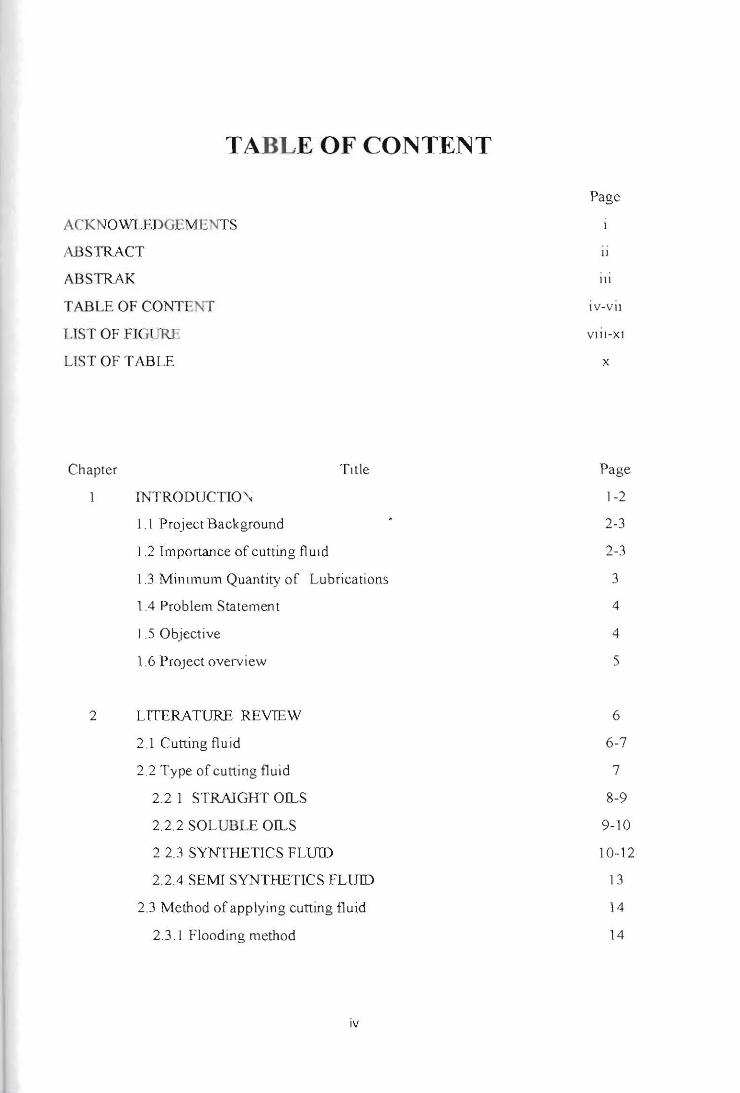
TABLE OF CONTENT
ACK NOWLEDGEME TS
ABSTRACT
ABSTRAK
TABLE OF CONTENT
USTOFFIG RE
LIST OF TABLE
Chapter TItle
INTRODUCTIO~,
1.1 Project Background
1.2 Importance of cutting flUId
1J Mintmum Quantity of Lubrications
1.4 Problem Statement
1.5 Objective
1.6 ProJect overv iew
2 LITERATURE REVTEW
2.1 Cutting fluid
2.2 Type of cutting fluid
2 .2 I STRAIGHT OILS
2.2.2 SOLUBLE OILS
22.3 SYNTHETICS FLUID
2.2.4 SEMI SYNTHETICS FLUID
23 Method of applying cutting fluid
2.3.1 Flooding method
Page
11
III
I V - V II
V III-Xl
x
Page
1-2
2-3
2-3
3
4
4
5
6
6-7
7
8-9
9-10
10-12
13
14
14
iv
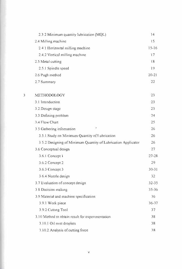
2.3 2 Minimum quantity lubrication (MQL)
2.4 Mtiling machine
241 Horizontal milling machine
2.4.2 Vertical milling machine
2.5 Metal cutting
2.5.1 Spindle speed
2.6 Pugh method
2.7 Summary
3 METHODOLOGY
3 .1 Introduction
3.2 Design stage
3.3 Defining problem
3.4 Flow Chart
3 5 Gathering information
3.5.1 Study on Minimum Quantity of Lubrication
35.2 Designing of Minimum Quantity of Lubrication Applicator
3.6 Conceptual design
3.6.1 Concept 1
3.6.2 Concept 2
3.6.3 Concept 3
3 6.4 Nozzle design
3.7 Evaluation of concept design
3 8 Decision making
3.9 Material and machine specification
3.9.1 Work piece
3.9.2 Cuttmg Tool
3.10 Method to obtain result for expenmentation
3.10.1 Od mist droplets
3.10.2 Analysis of cutting force
14
15
15-16
17
18
19
20-21
22
23
23
23
24
25
26
26
26
27
27-28
29
30-31
32
32-35
35-36
36
36-37
37
38
38
38
v
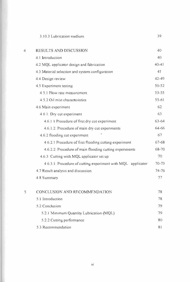
39 3.10.3 Lubrication medium
4 RESULTS AND DISCUSSION 40
4 .1 Int roductio n 40
4.2 MQL applicator design and fabrication 40-41
4.3 Material selection and system configuratJon 41
4.4 Design rev iew 42-49
4.5 Expe rim ent tes ting 50-52
4 S. I Flow rate measurement 53 -SS
4.S.2 O il mist characteris tics SS-6J
4.6 Main ex pe riment 62
4 6 I . Dry cut experiment 63
4.6.1 1 Procedure of firs t dry cut ex perim ent 63-64
4.6 .1.2. Procedure of main dry cut expenments 64-66
4 .6.2 flooding cut expenment 67
4 6.2. 1 Procedure of first flooding cutting experiment 67-68
4.6.2.2. Procedure of main flooding cutting expenments 68-70
4.6.3· Cutting with MQL applicator set up 70
4 6.3 .1. Procedure of cutting experiment wIth MQL applicator 70-73
4 .7 Result ana lysIs and discussion 74-76
4 8 Summary 77
S CONCLUS IO N AND RECOMMENDATION 78
S. I I.ntroductio n 78
5.2 Conc lusion 79
5.2.1 Mmlmum Quantity Lubrication (MQL) 79
5.2.2 Cutting peliorrnance 80
5 3 Recommendation 81
vi

REFRENCES
APPENDIX
vii
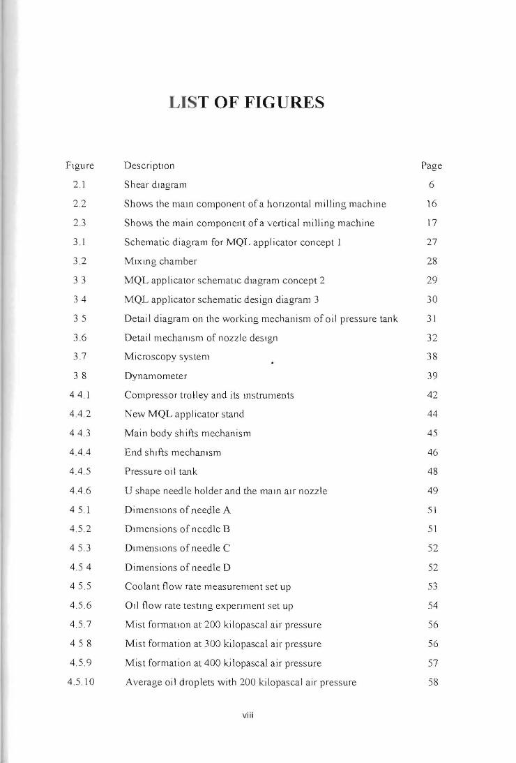
LIST OF FIGURES
hgure Descr i ptlon Page
2.1 Shear diagram 6
2.2 Shows the malO componen t ofa hOrizontal milli ng machine 16
2.3 Shows the ma in component of a verti ca l milling machine 17
3. 1 Schematic di agra m for MQL appl icalOr concep t I 27
3.2 M,xmg cha mbe r 28
33 MQL app li ca to r schematIc dJagram concept 2 29
3 4 MQL applicator schematic des ign diagram 3 30
35 Detai I diagram on the wo rking mechanism of oil pressure tank 31
3.6 Detail mechanism of nozzle deSIgn 32
3.7 Microscopy sys tem 38
3 8 Dynamometer 39
44 .1 Compresso r trolley and its Instruments 42
4.4.2 New MQL ap plicator stand 44
4 4. 3 Main body shifts mechanism 45
4.4.4 End shifts mechaDlsm 46
4 .4.5 Pressure o il tank 48
4.4 .6 U shape needle ho lde r and the main a IC nozzle 49
4 5. 1 DimenSIons of needle A 51
4.5.2 Dimens ions of needle B 51
45.3 D,mens lons of needle C 52
4.5 4 Dimensions of needle D 52
4 5.5 Coo lant flow rate measurement set up 53
4.5 .6 A,] flow rate testIng experiment set up 54
4.5. 7 Mist foonatlon at 200 kilopascal air pressure 56
458 Mist formation at 300 kilopascal air pressure 56
4.5 .9 Mist formation at 400 kilopascal air pressure 57
4.5 .10 Average oil droplets with 200 kilopascal air pressure 58
viii
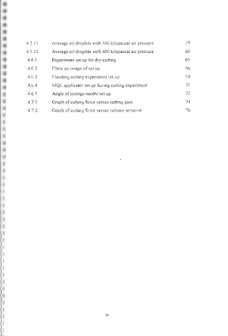
45 11 Average oJ! droplets with 300 kilopascal aIr pressure 59
45.12 Average oil droplets with 400 kilo pascal air pressure 60
4.6.1 Experiment set up for dry cutting 65
4.6.2 Close up image ofsel up 66
4.6.3 Floodmg cuning experiment set up 69
4.6.4 MQL applicator set up during cutting experiment 71
4.6 5 Angle of syringe needle set up 72
4.71 Graph of cutting force versus cuttmg pass 74
4.7.2 Graph of cutting force versus volume removal 76
,x
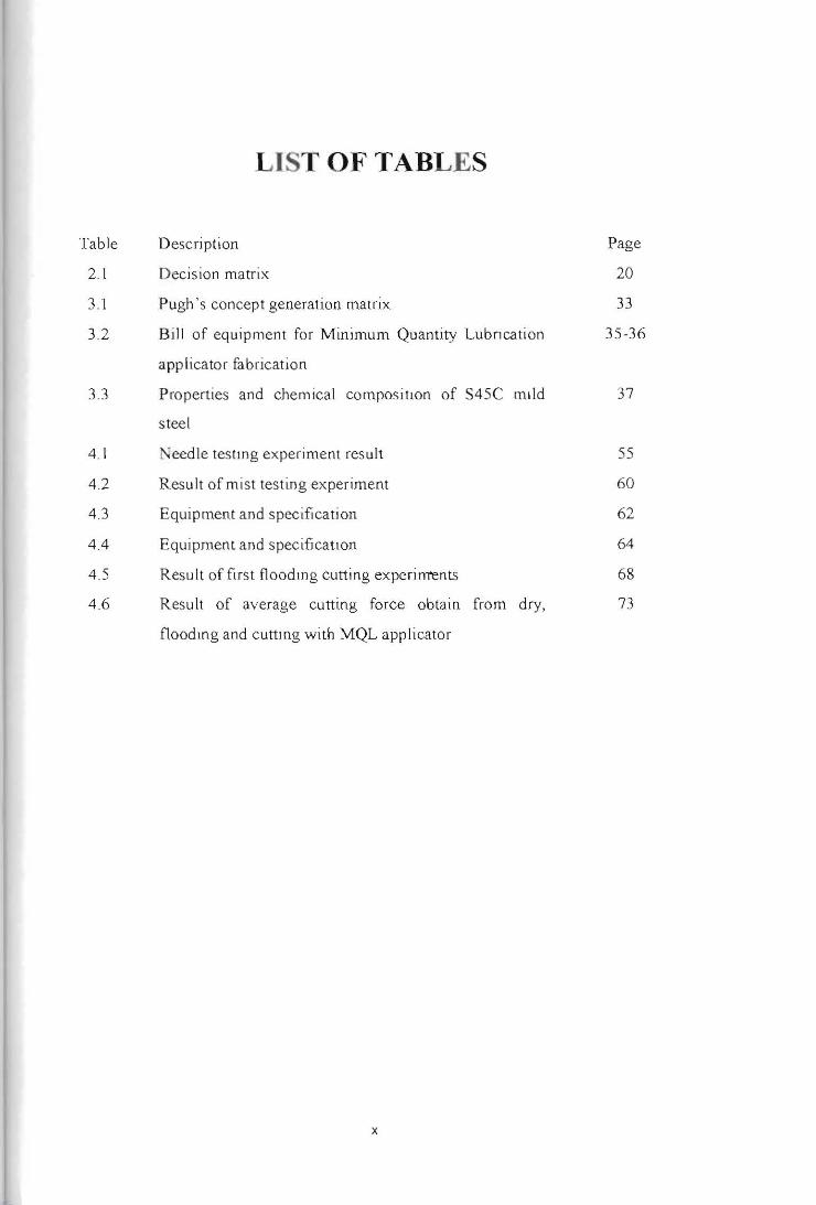
LIST OF TABLES
Table Description Page
2.1 Decision matri x 20
3.1 Pugh 's concep t generation matrix 33
3.2 Bill of equipment fo r Minimum Quantity Lu bncation 35-36
app li cator fabrication
3.3 Properties and chemical compos ition of S45C mild 37
s teel
4.1 "eedle testmg experiment result 55
4.2 Result of mist testing ex periment 60
4.3 Equipment and spec ifi ca ti on 62
4.4 Equipment and specification 64
4.5 Resu lt of first fl oodmg cutting experiments 68
4.6 R esu lt of average cutting force obtain from dry, 73
floodll1g and cutting with MQL applicator
x
CHAPTER 1
INTRODUCTION
J.I Project Background Demands for custom made parts and special machining works are in high In demand
nowadays. The mindset of using and patteming custom parts develops as technologies
nowadays are getting more advanced. Young generations really test the limIts of sImple
machining with production of parts has complex design Increasing in demands for high
productivity and good quality product causes the cause of machining to Increase. This
factor limits the customer range for affordabillty as most of them are perusing a lower cost
machining that can produce a high quality and high production of product. Machining
process spec ifically to metal cutting operations requires removal of material according to
the desIred length , diameter, length, height and specific surface fini shing of a product.
During this process, friction between the work piece and cuttUlg tool will generate heat. (T,
2014)
In high speed machining, variable like spindle speed, feed rdte and cutting depth
influence the friction between cutting tool and work piece. Hence, these three vanab les are
a main factor to the total heat produce during machining. By using cutting fluid Ul the
machining process, the generated heat can be reduces. The cutting fluid not only coo ls
down the work piece by removing the chip but also provide lubrication between the cuttmg
tool and work piece. Besides that, the cutting fluid also provides a layer of protection to the
work piece. TIllS property applies differently with different types of c utting fluid (Kim ,
Effect of the minimum quantity lubrication in high-speed end-milling of AlS[ D2 cold
worked die steel (62 HRC) by coated carbide tools, 2008)
1
Us 109 cutttng fluid in machining work eliminate the use of coo lant fluid which IS
hazardous when exposed to human and can cause dermatitls syndrome Using coolant fluid
effect the overall machining cost that includes the maintenance, fluid depletion and disposal
of them Eliminating this application may helps the machimng compani es to lower the
machining price and increase their finically (T, 2014), (L1U , 2015)
1.2 Importance of cutting fluid
There are two main functions of cutttng fluid, first they act as a lubrication agent in
low speed machining. Then, they act as a coolant agent in high speed machining. Not to
overlook that they also act as a medium who removes chips from cutting zone and provide
sufficient protection to machine tool and work piece against corrosion.
In low speed operating conditions, temperat~re produce form fflction between the
machine tool and work piece are not too high . Because of this, the cuttmg fluid acts as a
lubricator to reduce the fricBon and build-up-edge. For thIS s ituation, the suitab le coo ling
fluids used are o il based. The cutting tluld works to reduce the contact area between chip
and tool and Its effi ciency depends on the ability of penetrating in the chip-too l inter face
and to crea te a thin layer in the short available time This la yer is created by either chemical
reac tJon or phys ica l adsorption and must have a shearing res Istance lower than the
res istance of the material in the interface. In thIS way it will also act mdirectl y as a coo lant
because it reduces heat generation and therefo re cuttin g tempe rature.
In high speed opera ting conditions, temperatures generated from friction between
the machine tool and wo rk piece a re the ma in factor to be address. The cuttrng fluid fl ows
through both the machine too l and wo rk piece and dissipate heat generated. This lowers the
overa ll heat temperature during the machining process. For this operation, It IS mo re
SUItable to use a water based fluid as lubflcation properlles are secondary.
Efficiency of cutting fluid, mainly dependable on the different charactenstlcs of
cutllng fluid and suitability of machining operations. However, the efflclency cooler fluid
2
reduces when the cutting speed and cutting depth increases Despi te all this, the cutting
fluid also promotes some disadvantages to the machining operation. Chemical properties in
cutting fluid give out toxic when it changes in the form of a mist. This situation may cause
dermatitis, damages to respiratory and digestive system and also death to be human.
(Machado,2001)
1.3 Minimum Quantity of Lubrications The usages of c utting fluid are well known to contribute some health issue to the
working environment in the metal machining industries . One of the ways to reduce thiS risk
is to limit the usage of cutting fluid in the industries By introducing the minimum quantity
of lubrication method , this issue can be solved.
Minimum quantity lubrication uses a small amount of biodegradable oil droplets
mixed with compressed air is sprayed to the cutting area, this action helps to reduce the
cutting temperature and lubllcate the cutting tool. Using biodegradable oil is not only eco
friendly but there are non toxic. Thus, will not expose hazardous materia ls to the workers.
The low quantity of oil used in minimum quantity lubrication also helps the industry
economically as less cutting flUId IS bemg purchased.
The application of minimum quantity of Lubrication also increases the tool life as It
received a suffic ient amount of lubrication during the machming process , this situatIOn does
not always occur with the conventional flooding method . Not only that, the application of
minimum quantlty of lubrication also applicable to milling, turning and many more
machining operations (Lin , Mechanism of miOimum quantity lubrication In high-speed,
2007), (Machado, 2001) , (Hodzic, 2016)
1.4 Problem Statement In small manufacturing industry, the use of minimum quantity of lubrication is
restricted due to the high cost of installation Besides that, the parts of assembly for a
3
minimum quantity of lubrication appilcatlon need an authorised technIcians for installation
and maintenance work . These small manufacturing industries tend to app ly the flooding
and dry machimng method during machining process . Resulting from this , th e su rface
tinished and overa ll quali ty of end product may be compronllsed.
Not only that, the too l life also will be compromised when in a dry machining
process. This is due to lack of lubrication to the frictional forces between th e cutting tool
and work piece. Next the use of flooding method also consumes a large amount of cutting
fluid that affect the economic factor and is not environmental friendly. Using a large
amount of cuttin g fluid exposes the wo rking environment to hazardous che mica l and toxic
that causes irritation a nd death to be human .
1.5 Objective
In this research, th ere are several objectives that can be Iden tified'
1. To investi gate th e advantages and disadvantages of us ing conventional cutting flUid
2. To design a new type of minimum quantity of lubrication app li cator in milling
operation that is affordable and eco-friendly
3. To demonstrate the device performance under real minimum quantity of lubflcatlon
application.
We expect that a t the end of this ex periment, a ll th e objectives can be achieved s uccessfull y
in proper way and procedures.
1.6 Project overview
For thi s thesis project, chapter one is about the introd uction and background to the
study. All th e basic knowledge and components were mcluded m the first chapter. Next, the
literature review is presented in the second chapter This chapter provides al I the sources of
Information such as theory, concep t and functions regarding to the tItle to the proJect.
4
Chapter three describe the methodology used to conduct experiment and testing to the
material according to the chosen design concept All the result and findings from
experiments and testing are shown in chapter four. This chap ter also describes all th e
calculation and explanation for resu lt experiments. Finally, chapter five explains the
conclus ion to the pro ject and s tates any s ugges tion of improvement future used .
5
CHAPTER 2
LITERAT1JRE REVIEW
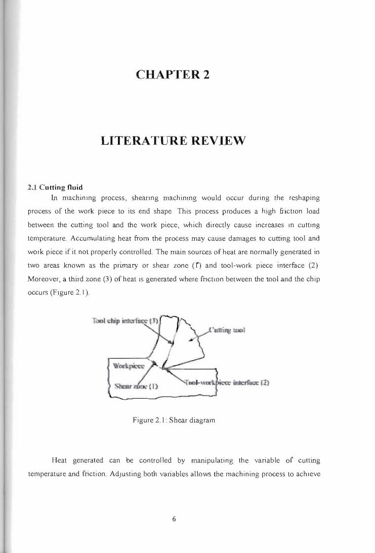
2.1 Cut1ing nuid
In machining process, sheaIlng machlnlng would occur during the reshaping
process of the wo rk piece to its end shape This process produces a high frictIOn load
between the cutting tool and the work piece, which directly cause increases III cutting
temperature. Accumulating heat fro m the process may cause damages to cutting tool and
work piece if it not properly contro ll ed. The main sources o f heat are normally generated in
two areas known as the primary or shear zone (0 and tool·work piece interface (2)
Moreover, a third zone (3) of heat IS generated where fnchon between the tool and the chip
occurs (Figure 2.1).
Figure 2. I • Shear diagram
Heat generated can be con trolled by manipulat ing the variable of cutting
temperature and fricti on. Adjusting both variables allows the machining process to achIeve
6
Its optimum efficiency as distinctive materials used to have distinct su itable cutting
temperature. A higher cutting temperature would be necessary to make the defonnation
process occur easily ; as 10 hot machinlOg processes. On the other hand , It generates
ex.cessive heat, which will affect tool life and in some cases the surface integrity of
components. (MULYADI, 2013)
The main functi on of cutting fluid is to provide a cooling action to the cuttin g zo ne
during the machining process In addition to Its coo ling actJon , the lubricating effec t of
cutting fluid makes a s ignifi cant contribution in friction reduc tion . Highest heat generated
was during the interfac ial face of the tool and chip, the presence of c utting lluid particles
will enhance the lubricat ing action over the face In addition, cutting flUid in CUttlOg
operati ons also removes the chips off the machined surface to prevent the ch ips from
scratching the machined surface. Cutting fluid also helps reduce enough friction between
the cutting tool and work piece so that it won't cause unnecessary heat. Nex.t cutting fluid
also provides a layer of protection for the machined surfuce to prevent chem ica l reaction
that cou ld promote co rro sion. The lubricant film also prevents the chips from being welded
to the machined surface (MULY ADI, 2013)
2.2 Type of c.utting fluid
There are mainly 4 types of cutting fluids used in industries
t. s traight o ds
2 soluble o il s
3. synthetic
4 semi synthetic
All th e different type of cutting flUids IS used on different applications depending on
their tnd,v,dual ' s properties. Blo-based cutting fluids have the potential to reduce the waste
treatment costs due to their inherently higher biodegradability and may reduce the
occupational health nsks assOCiated with petroleum-oil-based cutti ng fluids since they have
7
lower toxicIty. The output IS a healthIer and cleaner in the work environment, with less mist
in the all. (Lin, Mechanism of minimum quantIty lubrication in high-speed mdltng of
hardened steel, 2007)
2,2,1, STRAIGHT OILS (100% petroleum oil) (Lin, Mechanism of minimum quantIty
lubncatlOn in hIgh-speed milling of hardened steel, 2007)
Straight oils are cutting fluid that dose not con tam water, are basically petroleum
and mineral. They may have additives designed to improve specific properties In general,
these additIves improve the oil's wet abilrty, that is, the ability of the oil to coat the cutting
tool, work piece and metal fines Besides that, they also improve the oil's ability to handle
large amounts of metal fines, and help guard against microscopic weldmg 10 heavy-duty
machining. For extreme conditions, addItives (primarily with chlorine and sulfurize fatty
ods) may exceed 20%. These additives strongly enhance the ant! welding properties of the
product
Advantages of straight oil: I Straight oils have excellent lubricity between the workpiece and cutting tool, mainly
useful for low speed, low clearance machining operations and to achieve high
quality surface finishes.
2 Straight oil Increases tool life
3. Straight oils offer good rust protection
4. Straight oil also resist rancidity (bacteria cannot thrive unless water contaminates
the oil)
Disadvantages of straight oil I. High costing
2. Straight oil has poor heat dissipating properties and increased fire risk.
3. Straight oil creates a mist or smoke that IS envlfonmental friendly.
8
Recommended