Jawaharlal Nehru Engineering College
Department of Electronics and Telecommunications
Laboratory Manual
ANALOG CIRCUITS
For
Second Year Students
(Affiliated to B.A.T.U., Lonere)
Manual Made By
Prof S.A.Annadate
Prof S.D.Gavraskar
Author JNEC, Aurangabad

FOREWORD
It is my great pleasure to present this laboratory manual for second year engineering students for
the subject of Analog Circuit keeping in view the vast coverage required for visualization of
concepts of basic Analog Electronics circuit.
As a student, many of you may be wondering with some of the questions in your mind regarding
the subject and exactly that has been tried to answer through this manual.
Faculty members are also advised that covering these aspects in initial stage itself will greatly
relieve them in future, as much of the load will be taken care by the enthusiastic energies of the
students, once they are conceptually clear.
Prof S.A.Annadate
Prof S.D.Gavraskar
(ECT Department)

LABORATORY MANUAL CONTENTS
This manual is intended for the Second year students of Electronics & telecommunication
Branch in the subject of Analog Circuit. This manual typically contains Practical/Lab Sessions
related to Analog Circuits covering various aspects related the subject to enhance understanding
of the subject.
Students are advised to thoroughly go through this manual rather than only topics mentioned in
the syllabus, as practical aspects are the key to understanding conceptual visualization of
theoretical aspects covered in the books.
Good Luck for your Enjoyable Laboratory Sessions
Prof S.A.Annadate
Prof S.D.Gavraskar
(ECT Department)

SUBJECT INDEX
1. Do’s and Don’ts
2. Lab exercise:
1. Measurement of op-amp parameters viz. Input offset voltage, Bias current,
Slew rate and CMRR.
2. Op-amp applications –I: Integrator
Design and verify the frequency response of Integrator circuit using IC741.
3. Op-amp applications -II: Schmitt trigger.
To study Schmitt trigger circuit using op-amp 741.
4. Design a first order low pass Butterworth filters using op-amp.
5. Design a square wave generator using op-amp.
6. To study the operation of IC-565 as PLL and measure its free running
frequency.
7. Inverting Amplifier
8. Non inverting Amplifier
9. Summing Amplifier
10. Differentiator
11. RC phase shift oscillator using op amp
Quiz on the subject
Conduction of Viva-Voce Examination
Evaluation and Marking Systems

Do’s and Don’ts in Laboratory:
1. Do not handle any equipment before reading the instructions/Instruction manuals.
2. Do not apply voltage more than 15 V to IC 741.
3. Check CRO probe before connecting it.
4. Strictly observe the instructions given by the teacher/Lab Instructor.
Instruction for Laboratory Teachers::
1. Submission related to whatever lab work has been completed should be done during the next
lab session.
2. The promptness of submission should be encouraged by way of marking and evaluation
patterns that will benefit the sincere students.

Experiment No. :1
Aim : - Measurement of op-amp parameters viz. Input offset voltage, Bias current,
Slew rate and CMRR.
Apparatus : - IC 741, Resistors, Function generator, CRO, CRO probes, Dual power supply.
Circuit diagram:-
Fig 1: Input offset voltage
Fig 2: Bias current
RL10k
Rf100k
R11k
U1IDEAL

Fig.3 Measurement of Slew rate
Fig 4: Common Mode for CMRR
Fig 5: Differential Mode for CMRR
+
-
Vs110V
R21k
R310k
RL10k
Rf10k
R11k
U1IDEAL

Theory : -
Input Offset Voltage
Definition
Equation (If any)
Ideal Value and Value for IC 741
Input Bias Current
Definition
Equation (If any)
Ideal Value and Value for IC 741
Slew Rate
Definition
Equation (If any)
Ideal Value and Value for IC 741
CMRR
Definition
Equation (If any)
Ideal Value and Value for IC 741
Procedure : - For Input Offset Voltage
1. Make connections as shown in figure.
2. Measure the output voltage.
3. Calculate the value of input offset voltage.
For Input Bias Current
1. Make connections as shown in figure.
2. Measure the output voltage.
3. Calculate the value of input bias current by using given formula.
For Slew Rate
1. Make connections as shown in figure.
2. Note down the value of Vpeak.
3. Vary the frequency of input voltage & observe the output waveform.
4. Note the value of frequency at which output waveform start distorting.
5. Calculate the value of slew rate using given formula.

For CMRR
1. Make connections as shown in the figure.
2. Give i/p voltage of 1v peak to peak.
3. Measure the differential & common mode output.
4. Calculate Ad, Acm, & CMRR in db using formula.
Observation :- For Input offset voltage and Bias current
Voo (For Vios) Vo (For Ib)
For Slew rate
Input frequency Remark
For CMRR
Vo1= Vo2=
Formulae : - For Input offset voltage
Vio= Voo /(1+ Rf/R1)
For bias current
Vo= IB*RF
IB=Vo/RF
For Slew rate
For CMRR
CMRR=20 log(Ad/Ac)

Ad = Vo1/Vin
Acm = Vo2/Vin
CMRR=20 log(Vo1/Vo2)
Result :-
Sr. No. Op Amp Parameter Theoretical value
for IC 741
Calculated Value
1 Input Offset Voltage
2 Input Bias Current
3 Slew Rate
4 CMRR
Conclusion :-

Experiment No. :2
Aim : - Design and verify the frequency response of Integrator circuit using IC741.
Apparatus : - IC 741, Resistors, Capacitor, Function Generator, CRO, CRO probes, Dual
Power Supply.
Theory : -
Integrator definition
Derivation of output
Input and output waveforms for standard test signals
Frequency Response
Circuit Diagram:-
Procedure: -
1. Make the connections as per circuit diagram.
2. Switch on the power supply.
3. Apply input from function generator i.e. sinewave of amplitude 1V (p-p) (the input
should be such that T > RF.CF)
4. Connect output of integrator to CRO by probe and observe the waveforms.
5. Vary input frequency and observe the change in output waveforms.
6. For different frequencies and note the corresponding output Voltage.
Cf1uF
+
-
Vs11V
ROM1k
RL10k
Rf10k
R11k
U1IDEAL

7. Calculate the Gain using the formula and plot the graph between frequency and
Gain.
Observations:-
Cutoff Frequency :- fc = 1/ 2πRfCf
Result :- Calculated Value of cutoff frequency = ___________
Observed Value of cutoff frequency = ___________
Conclusion :-
Sr. No.
Frequency (Hz)
V0
Gain = V0 / Vi
Gain in dB
= 20log( V0 / Vi)
1 100
2 300
3 500
4 800
5 1k
6 3k
7 5k
8 8k
9 10k
10 15k
11 20k

Experiment No. 3:
Aim : - To study Schmitt trigger circuit using op-amp 741.
Apparatus : - IC 741, Resistors, Function generator, CRO, CRO probes, Dual power supply.
Circuit diagram:-
Theory :-
Inverting Shmitt trigger
Non Inverting Shmitt trigger
Applications
Procedure :- 1. Make connections as shown in figure.
2. Apply sinewave input from function generator.
3. Observe the input as well as output waveform on CRO.
4. Plot the waveforms on graph paper.
5. Draw hysteresis loop.
Formula :-
VUT = +Vsat * (R2 / (R1 + R2) ) VLT = -Vsat * (R2 / (R1 + R2))
Observations :-
VLT = VUT =
Result :-
Sr. No Calculated Value Observed Value
1 VUT
2 VLT
Conclusion :-

Experiment No. :4
Aim :- Design a first order low pass Butterworth filter using op-amp..
Apparatus :- IC 741, Resistors, Capacitor, Function Generator, CRO, CRO probes,
Dual Power Supply.
Circuit diagram:-
RF = 10k, R1 = 1k, R = 1k, C = 0.01µF
Theory:-
Active Filter
First order Low Pass Butterworth filter
Frequency response and cut off frequency
Procedure:-
1. Make the connections as per circuit diagram.
2. Switch on the power supply.
3. Apply input from function generator i.e. sine wave of amplitude 1V (p-p)
4. Connect output of LPF to CRO by probe and observe the waveforms.
5. Vary input frequency and observe the change in output waveforms.
6. For different frequencies and note the corresponding output Voltage.
7. Calculate the Gain using the formula and plot the graph between frequency and
Gain.

Observations :-
Cutoff Frequency :- fc = 1/ 2πRC
Result :- Calculated Value of cutoff frequency = ___________
Observed Value of cutoff frequency = ___________
Conclusion :-
Sr. No.
Frequency (Hz)
V0
Gain = V0 / Vi
Gain in dB
= 20log( V0 / Vi)
1 100
2 300
3 500
4 800
5 1k
6 3k
7 5k
8 8k
9 10k
10 15k
11 20k 12 50k
13 80k
14 100k

Experiment No. :5
Aim :- Design a square wave generator using op-amp.
Apparatus :- IC 741, Resistors, Capacitor, Function Generator, CRO, CRO probes,
Dual Power Supply.
Circuit diagram:-
Theory : -
Working of square wave generator circuit
Define duty cycle
Derive the expression for output frequency of square wave
Procedure : -
1. Make the connections as per circuit diagram.
2. Switch on the power supply.
3. Observe output waveform on CRO.
4. Measure the time period and calculate the practical frequency of square wave.
5. Calculate the theoretical value of frequency by given formula.
6. Plot waveform on graph paper.
C0.01uF
RL10k
R10k
R2
10k
R1
1k
U1IDEAL

Formulae : - fo = 1/2RC ln ((2R1+R2)/R2)
Observations :-
fo =
Result : - Calculated Value of output frequency = ___________
Observed Value of output frequency = ___________
Conclusion : -

Experiment No.- 6
Aim : - To study the operation of IC-565 as PLL and measure its free running
frequency.
Apparatus :- IC 565, Resistors, Capacitor, Dual Power Supply, Digital Multimeter.
Circuit diagram:-
Theory : -
IC 565:
Description : -
The Signetics SE/NE 560 series is monolithic phase locked loops. The SE/NE 560, 561,
562, 564, 565, & 567 differ mainly in operating frequency range, power supply requirements and
frequency and bandwidth adjustment ranges. The device is available as 14 Pin DIP package and
as 10-pin metal can package. Phase comparator or phase detector compare the frequency of
input signal fs with frequency of VCO output fo and it generates a signal which is function of
difference between the phase of input signal and phase of feedback signal which is basically a

d.c voltage mixed with high frequency noise. LPF remove high frequency noise voltage. Output
is error voltage. If control voltage of VCO is 0, then frequency is center frequency (fo) and mode
is free running mode. Application of control voltage shifts the output frequency of VCO from fo
to f. On application of error voltage, difference between fs & f tends to decrease and VCO is said
to be locked. While in locked condition, the PLL tracks the changes of frequency of input signal.
Block Diagram of IC 565
Specifications:
1. Operating frequency range : 0.001 Hz to 500 KHz
2. Operating voltage range : ±6 to ±12V
3. Inputs level required for tracking : 10mV rms minimum to 3v (p-p) max.
4. Input impedance : 10 KΩ typically
5. Output sink current : 1mA typically
6. Drift in VCO center frequency
(fout) with temperature : 300 PPM/oC typically
7. Drif in VCO centre frequency with
supply voltage : 1.5%/V maximum
8. Triangle wave amplitude : typically 2.4 VPP at ± 6V

9. Square wave amplitude : typically 5.4 VPP at ± 6V
10. Output source current : 10mA typically
11. Bandwidth adjustment range : < ±1 to > ± 60%
Pin Configuration:
How to calculate the Free running frequency, Lock range and capture range for IC 565?
If R1, C1 and C2 are the externally connected components to the PLL IC 565 as shown in
figure above then the Free running frequency, Lock range and capture range can be calculated as
Free running frequency fout = 1.2/4R1C1 Hz
Lock range, FL and Capture range, fc can be calculated as
Applications:
1. Frequency multiplier
2. Frequency shift keying (FSK) demodulator

3. FM detector
Procedure: -
1. Make the connections as per circuit diagram.
2. Switch on the power supply.
3. Measure the frequency of output waveform which is free running frequency of
PLL.
Observation: -
Free running frequency of PLL = _______ Hz.
Formula: -
Free running frequency fout = 1.2/4R1C1 Hz
Result :- Calculated Value of Free running frequency = ___________
Observed Value of Free running frequency = ___________
Conclusion:-

Experiment No 7
INVERTING AMPLIFIER
Aim: To design an Inverting Amplifier for the given specifications using Op-Amp IC 741.
Apparatus : Function Generator, CRO , Dual Power supply , Bread Board , Resistors , IC 741
Theory : 1. Working of an Inverting amplifier
2. Justify Vo = - ACL Vi
3. Output waveform for sine wave as input
Circuit Diagram :
Procedure:
1.. Check the components.
2. Setup the circuit on the breadboard and check the connections
3. Switch on the power supply.
4. Give 1 Vpp / 1 KHz sine wave as input.
5. Observe input and output on the two channels of the oscilloscope simultaneously.
6. Note down and draw the input and output waveforms on the graph.
7. Verify the input and output waveforms are out of phase.
8. Verify the obtained gain is same as designed value of gain.
Design:
Gain of an inverting amplifier Av = Vo/Vin = - Rf / Ri
The required gain = 10,
That is Av = - Rf/ Ri = 10
Let Ri = 1KΩ, Then Rf = 10KΩ

Observations:
Vin = 1 Vpp
Vo=?
Gain, Av = Vo/Vin =?
Observed phase difference between
Result :
Graph:

Experiment No. 8
NON- INVERTING AMPLIFIER
Aim: To design and setup a non-inverting amplifier circuit with OPAMP IC 741C
Apparatus: Function Generator, CRO , Dual RPS , Bread Board , Resistors , IC 741
Theory: 1. Working of an Inverting amplifier
2. Justify VO = 1+ [RF/R1]
3. Output waveform for sine wave as input.
Circuit Diagram :
Procedure:
1. Check the components.
2. Setup the circuit on the breadboard and check the connections.
3. Switch on the power supply.
4. Give 1 Vpp / 1 KHz sine wave as input.
5. Observe input and output on the two channels of the CRO simultaneously.
6. Note down and draw the input and output waveforms on the graph.
7. Verify the input and output waveforms are in phase.
8. Verify the obtained gain is same as designed value.
Design:
Gain of an inverting amplifier Av=Vo/Vin = (1+Rf)/ Ri,
Let the required gain be 11,
Therefore Av= (1+Rf)/ Ri= 11
Rf/ Ri = 10
Take Ri= 1KΩ, Then Rf = 10KΩ

Observations:
Vin = 1Vpp
Vo = ?
Gain Av = Vo/Vin =?
Observed phase difference between the input and the output on the CRO =?
Result:
Graph:

Experiment No. 9
SUMMING AMPLIFIER
Aim: To design and setup a summing amplifier circuit with OP AMP 741C for a gain of 2
and verify the output.
Apparatus: Function Generator, CRO , Dual RPS , Bread Board , Resistors , IC 741
Theory: 1. Working of summing amplier
2. Prove Vo = - ( Rf/ Ri )(V1+V2)
3.Application of summing amplifier
Circuit diagram
Procedure :
1. Check the components.
2. Setup the circuit on the breadboard and check the connections.
3. Switch on the power supply.
4. Give V1 =V2 = +1.5V DC with polarity as shown in fig.1.
5. Make sure that the CRO selector is in the D.C. coupling position.
6. Observe input and output on two channels of the oscilloscope simultaneously.
7. Note down and draw the input and output waveforms on the graph.
8. Verify that the output voltage is -6VDC
Design:
The output voltage of an inverting summing amplifier is given by
Vo = -( Rf / Ri )(V1+V2)
Let Ri = 1.1KΩ
Then Rf = 2.2KΩ ,
Vo = -2(V1+V2)

Observation:
V1= 1.5 DC
V2= 1.5 DC
Then VO=?
Result:

Experiment No. 10
DIFFERENTIATOR
Aim: To design and setup a Differentiator circuit using OP AMP 741C and plot their pulse
response.
Apparatus: Function Generator, CRO , Dual RPS , Bread Board , Resistors , IC 741
Theory : 1. Working of Differentiator
2. Prove Vo= - RfCd(Vin)/dt.
Circuit diagram:
Procedure:
1. Check the components.
2. Setup the circuit on the breadboard and check the connections.
3. Switch on the power supply.
4. Keep the oscilloscope in AC coupling mode.
5. Give Vi= 2Vpp, 1KHz square wave.
6. Observe input and output on two channels of the oscilloscope simultaneously.
7. Note down and draw the input and output waveforms on the graph
Design :
Given f = 1 KHz
T = 1/f = 1ms
Design equation is T = 2πRfC
Let C = 0.01μF
Rf = 15KΩ
Let Ri = Rf/10 = 1.5KΩ
Result :
Graph:

Experiment No. 11
RC PHASE SHIFT OSCILLATOR USING OP AMP
Aim: To Design and setup a RC phase shift oscillator using Op-Amp 741 and (i) Plot the
output waveform (ii) Measure the frequency of oscillation.
Apparatus: : Function Generator, CRO , Dual RPS , Bread Board , Resistors , Capacitors ,IC 741.
Theory: 1. Working of RC phase shift oscillator
2. Prove F osci =1
2𝜋𝑅𝐶√6
Circuit diagram:
Procedure :
1. Check the components.
2. Setup the RC phase shift oscillator circuit on the breadboard and check the
connections.
3. Switch on the power supply.
4. Observe output voltage on oscilloscope.
5. Draw the waveforms on the graph.
6. Measure the frequency of oscillation
Design :
F osci =1
2𝜋𝑅𝐶√6
Let f = 1 KHz, and C= 0.01μF
R = 6.8KΩ
Gain = 29
Rf/R1 = 29
If R1 = 3.3KΩ ; Rf = 95.7KΩ Use 100KΩ pot

Observations:
Measured frequency of oscillation is =?
Graph:

3. Quiz on the subject:
1. What are the values of high input impedance , low output impedance & high voltage gain
obtained in operational amplifier
a)2M, 50, 1M b) 2K, 5k, 1M c) 2M, 75, 1M d)2M, 75, 1K
2. The CMRR of good quality op-amp is of the order of
a) 12 dB b) 25 dB c)100 dB d) 120 dB
3. The frequency at which differential gain in op-amp is zero dB is known as
a) unity gain crossover frequency b) resonant frequency
c) 3 dB frequency d) zero frequency
4. Compared to non-inverting amplifier, the gain of inverting amplifier using identical op-
amp is
a) equal b) slightly smaller c) slightly greater d) very large
5. Op-amp operating in its non-inverting saturation region can convert a sine wave into
a) sine wave b) triangular wave c) square wave d) saw tooth wave
6. Gain of an op-amp inverting amplifier with an input of 0.25 V & output of 17.5 V is
a) 50 b) 40 c) 80 d) 70
7. Closed loop voltage gain of ideal non-inverting op-amp is given by
a) 1R
R f b)
1R
R f c)
1
1R
R f d)
fR
R1
8. Closed loop voltage gain of ideal inverting op-amp is given by
a) 1R
R f b)
1R
R f c)
1
1R
R f d)
fR
R1
9. The op-amp shown below has AV=20,000 & ZO=20. The approximate VO is
a) 2V b) 3V c) 60 V d) 2mV
10. An op-amp has gain of 50 & bandwidth of 100 KHz. Its unity gain frequency is
a) 5 MHz b) 50 MHz c) 100KHz d) 50 Hz
+15 V
-15 V
2
3
6
4
7
741
1k 1k
10k
20V
-80V
VO

11. Which of the following op-amp system is a linear system.
a) Integrator b)Clipper c) Sample& Hold d) square wave
12. Which of the following op-amp system is a linear system.
a) current to voltage converter b) Logarithmic c)comparator
d)Square wave generator
13. Which of the following op-amp system is a nonlinear system.
a) Voltage to current converter b) voltage follower c) Active filter d) sample & hold
14. The op-amp circuit below behaves as a
a) Integrator b) Differentiator c)voltage follower d) Comparator
15. An op-amp Schmitt trigger is basically an comparator with
a) negative feedback b) positive feedback
c) open loop configuration d) none of these
16. An op-amp zero crossing detector is basically
a) cosine to sine wave converter b) sine to cosine wave converter
c) sine to square wave converter d) sine to triangular wave converter
17. Compared to open loop bandwidth of close loop is
a) equal b) less c) greater d) none of these
18. The op-amp circuit below behaves as a
a) low pass filter b) high pass filter c) buffer amplifier d) adder
19. Input impedance of Ideal op-amp should be
a) 100 b) zero c) 1 M d) Infinite
+15 V
-15 V
2
3
6
4
7
741
10k
10k
10k
18k
0.01
V
O
S
+15 V
-15 V
2
3
6
4
7
741
20. CMRR of Ideal op-amp should be
a) 100 b) zero c) 1 M d) Infinite
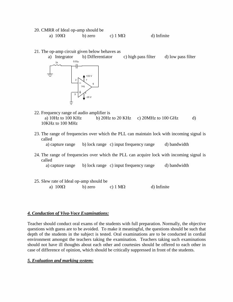
21. The op-amp circuit given below behaves as
a) Integrator b) Differentiator c) high pass filter d) low pass filter
22. Frequency range of audio amplifier is
a) 10Hz to 100 KHz b) 20Hz to 20 KHz c) 20MHz to 100 GHz d)
10KHz to 100 MHz
23. The range of frequencies over which the PLL can maintain lock with incoming signal is
called
a) capture range b) lock range c) input frequency range d) bandwidth
24. The range of frequencies over which the PLL can acquire lock with incoming signal is
called
a) capture range b) lock range c) input frequency range d) bandwidth
25. Slew rate of Ideal op-amp should be
a) 100 b) zero c) 1 M d) Infinite
4. Conduction of Viva-Voce Examinations:
Teacher should conduct oral exams of the students with full preparation. Normally, the objective
questions with guess are to be avoided. To make it meaningful, the questions should be such that
depth of the students in the subject is tested. Oral examinations are to be conducted in cordial
environment amongst the teachers taking the examination. Teachers taking such examinations
should not have ill thoughts about each other and courtesies should be offered to each other in
case of difference of opinion, which should be critically suppressed in front of the students.
5. Evaluation and marking system:
+15 V
-15 V
2
3
6
4
7
741
0.01 1k

Basic honesty in the evaluation and marking system is absolutely essential and in the process
impartial nature of the evaluator is required in the examination system to become. It is a wrong
approach or concept to award the students by way of easy marking to get cheap popularity
among the students, which they do not deserve. It is a primary responsibility of the teacher to
see that right students who are really putting up lot of hard work with right kind of intelligence
are correctly awarded.
The marking patterns should be justifiable to the students without any ambiguity and teacher
should see that students are faced with just circumstances.
Recommended