Demand Side Management with LONWORKS®
Power Line Transceivers
December 1996 LONWORKS Engineering Bulletin
Introduction
Demand side management (DSM) is the process of shifting the demand for energyfrom expensive peak periods to times when energy can be most efficiently andinexpensively delivered to customers. Through a combination of economicincentives, such as variable energy rates based on time-of-day usage, and forcedservice interruptions of appliances such as air conditioner and spa heaters(shedding), utilities shift energy consumption into off-peak hours when generatingcapacity is not at a premium. Off-peak energy consumption provides more efficientuse of energy generating capacity, and prevents—or at least forestalls—the need tobuild expensive new generating capacity to meet peak loads.
This document describes the use of LONWORKS for residential DSM applications.LONWORKS provides a highly refined and reliable communication scheme based onan open protocol, LONTALK®, that supports bi-directional communications, cancommunicate over virtually any medium, and can be installed and maintainedeasily using a client-server network management architecture. These features, andspecifically the availability of a robust power line signaling technology, makeLONWORKS ideal for residential DSM applications. The sections that follow includean overview of DSM systems, a description of the LONWORKS PLT-21 Power LineTransceiver, a review of the electrical wiring in a typical North American residence,and a detailed analysis of the coupling circuits needed to implement a reliable powerline signaling system.
DSM Overview
DSM requires a sophisticated control and communication infrastructure in order tofunction. The control network must carry rate information and load sheddingcommands from the utilities to the home or building occupants, and returncustomer inquiries and consumption information needed to calculate utility bills. Ifadditional services such as remote control and security monitoring are supportedthen these must be transmitted as well.
Large DSM systems place a heavy burden on the network management architectureused to install, monitor, control, and maintain hundreds of thousands of electronicmeters, customer interface units, load shed devices, and related equipment.Typically there are many technicians that need simultaneous access to the networkmanagement infrastructure as they commission new devices, modify network
LONWORKS Engineering Bulletin Demand Side Management with LONWORKS Power Line Transceivers
2
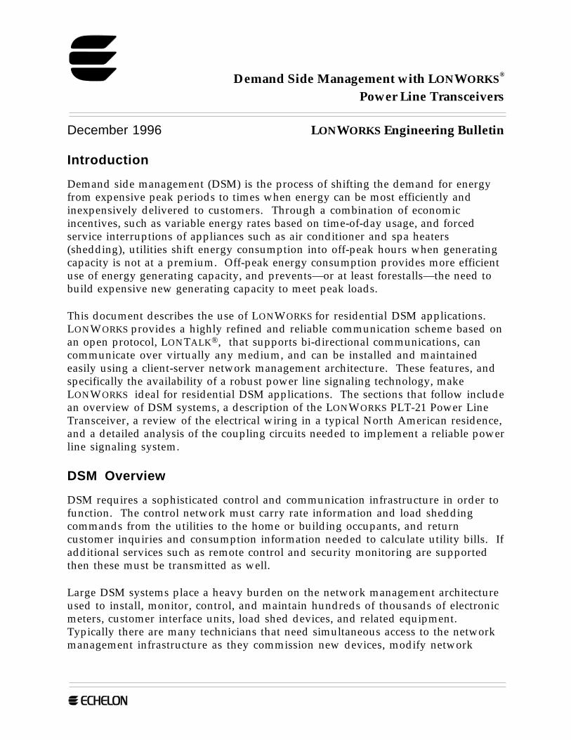
operation, and service customer requests. The overall communication and controlinfrastructure is summarized in figure 1.
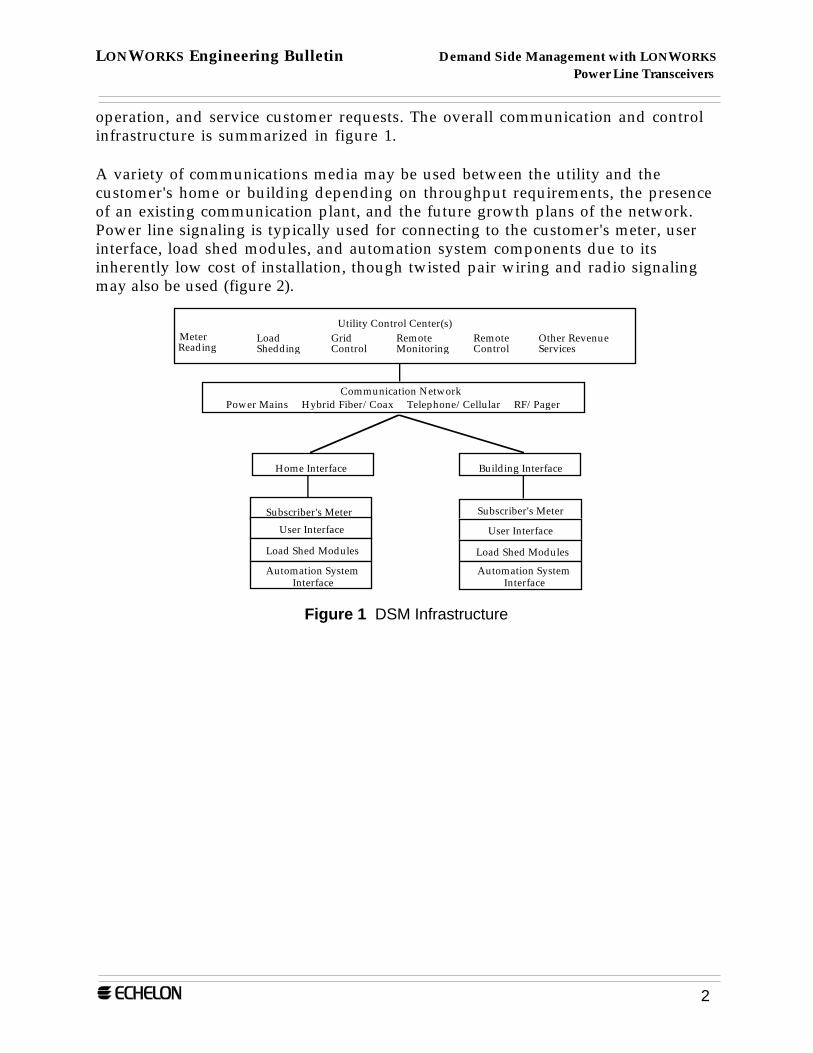
A variety of communications media may be used between the utility and thecustomer's home or building depending on throughput requirements, the presenceof an existing communication plant, and the future growth plans of the network.Power line signaling is typically used for connecting to the customer's meter, userinterface, load shed modules, and automation system components due to itsinherently low cost of installation, though twisted pair wiring and radio signalingmay also be used (figure 2).
Utility Control Center(s)MeterReading
LoadShedding
RemoteControl
RemoteMonitoring
Other RevenueServices
GridControl
Power Mains Hybrid Fiber/Coax Telephone/Cellular RF/PagerCommunication Network
Home Interface Building Interface
Subscriber's Meter
User Interface
Load Shed Modules
Automation System Interface
Subscriber's Meter
User Interface
Load Shed Modules
Automation System Interface
Figure 1 DSM Infrastructure
LONWORKS Engineering Bulletin Demand Side Management with LONWORKS Power Line Transceivers
3
Outdoor Lighting
Spa Heater/Pool Pump
Electronic Meter &
Washer & Dryer
Smart Outlets
Air Conditioner
Electric Water Heater
GatewayTo DSM
Electric Range
Dimmer
Energy Management Controller
Figure 2 Typical DSM Control Network
LONWORKS Power Line Transceivers
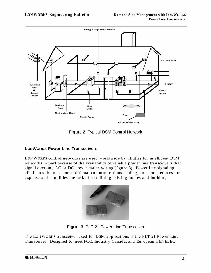
LONWORKS control networks are used worldwide by utilities for intelligent DSMnetworks in part because of the availability of reliable power line transceivers thatsignal over any AC or DC power mains wiring (figure 3). Power line signalingeliminates the need for additional communications cabling, and both reduces theexpense and simplifies the task of retrofitting existing homes and buildings.
Figure 3 PLT-21 Power Line Transceiver
The LONWORKS transceiver used for DSM applications is the PLT-21 Power LineTransceiver. Designed to meet FCC, Industry Canada, and European CENELEC
LONWORKS Engineering Bulletin Demand Side Management with LONWORKS Power Line Transceivers
4
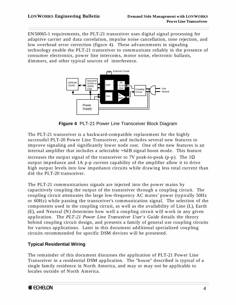
EN50065-1 requirements, the PLT-21 transceiver uses digital signal processing foradaptive carrier and data correlation, impulse noise cancellation, tone rejection, andlow overhead error correction (figure 4). These advancements in signalingtechnology enable the PLT-21 transceiver to communicate reliably in the presence ofconsumer electronics, power line intercoms, motor noise, electronic ballasts,dimmers, and other typical sources of interference.
TXAMP
RXFrontEnd
DSP
D/A
EPROM(3150)
Neuron®3120® or3150®Chip Coupling
Circuit
External Crystal
LineNeutral
PowerSupply
PLT-21
Figure 4 PLT-21 Power Line Transceiver Block Diagram
The PLT-21 transceiver is a backward-compatible replacement for the highlysuccessful PLT-20 Power Line Transceiver, and includes several new features toimprove signaling and significantly lower node cost. One of the new features is aninternal amplifier that includes a selectable +6dB signal boost mode. This featureincreases the output signal of the transceiver to 7V peak-to-peak (p-p). The 1Ωoutput impedance and 1A p-p current capability of the amplifier allow it to drivehigh output levels into low impedance circuits while drawing less total current thandid the PLT-20 transceiver.
The PLT-21 communications signals are injected into the power mains bycapacitively coupling the output of the transceiver through a coupling circuit. Thecoupling circuit attenuates the large low-frequency AC mains’ power (typically 50Hzor 60Hz) while passing the transceiver's communication signal. The selection of thecomponents used in the coupling circuit, as well as the availability of Line (L), Earth(E), and Neutral (N) determine how well a coupling circuit will work in any givenapplication. The PLT-21 Power Line Transceiver User's Guide details the theorybehind coupling circuit design, and presents a family of general use coupling circuitsfor various applications. Later in this document additional specialized couplingcircuits recommended for specific DSM devices will be presented.
Typical Residential Wiring
The remainder of this document discusses the application of PLT-21 Power LineTransceiver in a residential DSM application. The "house" described is typical of asingle family residence in North America, and may or may not be applicable tolocales outside of North America.
LONWORKS Engineering Bulletin Demand Side Management with LONWORKS Power Line Transceivers
5
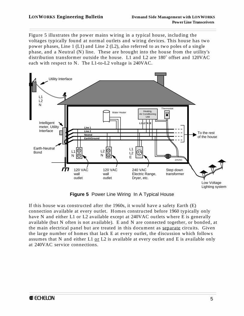
Figure 5 illustrates the power mains wiring in a typical house, including thevoltages typically found at normal outlets and wiring devices. This house has twopower phases, Line 1 (L1) and Line 2 (L2), also referred to as two poles of a singlephase, and a Neutral (N) line. These are brought into the house from the utility'sdistribution transformer outside the house. L1 and L2 are 180˚ offset and 120VACeach with respect to N. The L1-to-L2 voltage is 240VAC.
L1N
L2N
L1L2E
120 VACwall outlet
240 VACElectric Range, Dryer, etc.
120 VACwall outlet
Intelligent meter, Utility Interface
Step down transformer
Low Voltage Lighting system
Line 1
Line 2
Neutral
Earth/Ground
To the rest of the house
Utility Interface
Heating,Air Conditioning
Unit
Thermostat
24VAC
L1 L2 N E
L1L2N
Earth-NeutralBond
Water Heater
Figure 5 Power Line Wiring In A Typical House
If this house was constructed after the 1960s, it would have a safety Earth (E)connection available at every outlet. Homes constructed before 1960 typically onlyhave N and either L1 or L2 available except at 240VAC outlets where E is generallyavailable (but N often is not available). E and N are connected together, or bonded, atthe main electrical panel but are treated in this document as separate circuits. Giventhe large number of homes that lack E at every outlet, the discussion which followsassumes that N and either L1 or L2 is available at every outlet and E is available onlyat 240VAC service connections.
LONWORKS Engineering Bulletin Demand Side Management with LONWORKS Power Line Transceivers
6
Establishing Reliable Power Line Communications
In general, optimizing the performance of a power line transceiver involves acombination of proper node design and the selection of an optimal coupling circuit.Proper node design is covered in detail in the PLT-21 Users Guide.
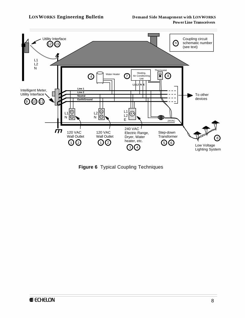
Figure 6 presents the coupling techniques that have been used successfully to establishreliable power line signaling in homes. Each coupling circuit is identified with anumber which refers to the schematic and parts list associated with that circuit. Insome cases the reader is referred to a specific user's guide for the schematic and parts.Depending on the specific DSM application, one, many, or all of these circuits may beused in a home.
The choice of coupling circuits for each individual DSM device communicating onthe power mains is the key to installing a robust, reliable system. For DSM systemapplications, the high cost of service calls and the need for the highest degree ofcustomer satisfaction make it prudent to maximize system communications marginswhere possible. The coupling circuits described here have been optimized formaximum performance by taking advantage of the following key concepts.
• The combination of coupling methods has been chosen to maximizecommunication margin between single phase devices and two-phase devices. Thecoupling circuits in this document avoid the 6dB (or more) signal loss that wouldoccur if one attempted to communicate between a device with a coupling circuitconnected only between L1 and L2 (i.e. no N or E connection) and a device whosecoupling circuit was connected to L1 or L2 and N. This loss is significant indesigning a DSM system with the level of reliability required in mass deployment.This loss is avoided in the case of two phase loads (such as water heaters andelectric ranges) that connect to both phases but do not have a neutral connection.Such loads do, however, have (by code) an Earth connection. By coupling to thetwo lines relative to earth and taking advantage of the E-N bond present at thehouse power entry, robust communication between the two phase load and asingle phase node (perhaps a user interface plugged into a wall socket) ismaintained.
• Each coupling circuit has been “tuned” for its specific intended location. In orderto couple maximum transmit signal onto the mains, each coupling circuitemploys a resonant circuit (typically L2 and C1) that is tuned to have very lowimpedance at the PLT-21 communication frequency. The value of L2 is “pre-tuned” in order to take in to account the typical wiring inductance that would bepresent at the location where a particular DSM device would be installed. Thus
LONWORKS Engineering Bulletin Demand Side Management with LONWORKS Power Line Transceivers
7
the “pre-tuning” of the resonant circuit is different for a DSM device located near abreaker panel, which is a non-inductive load point, than at a distributiontransformer, which is separated from the home by mains wiring that presents asignificant series inductance.
The same issue of 6dB (or more) loss between a two phase connection and a singlephase connection is present when adding powerline communication to an electricmeter. In this case the loss is avoided by adding a “Neutral pigtail” to the meterwhich is screwed into the meter sheet metal housing. The meter sheet metalhousing is always tied to Neutral/Earth, thus the meter coupling circuit will beconnected to both phases relative to Neutral/Earth and avoid the loss incommunication system margin.
• Phase coupling has been added to minimize signal loss between single phasedevices on different phases. Because the distribution transformer windingseffectively isolate communication signal frequencies between phase 1 and phase 2,communication between two single phase devices on different phases becomespossible only due to the inductive coupling between the two phases that occursdue to the proximity of the two wires as they run between the distributiontransformer and the home. A communications signal crossing from one phase tothe other via this inductive coupling is subject to 10-30 dB of attenuation. Theextra 6dB of transmit signal power available in the PLT-21 helps to mitigate thisloss and is sufficient for many consumer applications. Once again, for DSM systemapplications the high cost of service calls and the need for the highest degree ofcustomer satisfaction make it prudent to maximize system communicationmargin where possible, thus the DSM coupling circuits in this document show theaddition of phase coupling circuits where appropriate.
• A means for devices on L1 or L2 and low voltage devices (e.g., 24VAC) to inter-communicate has been provided. Since 60Hz step down transformers highlyattenuate power line communication signals, coupling circuits that bridge thesetransformers have been designed for systems that extend communications onto alow voltage home network. Both stand alone versions are presented as well as aversion that combines both mains and low voltage coupling. Also, an example ofa low voltage coupling circuit is presented.
LONWORKS Engineering Bulletin Demand Side Management with LONWORKS Power Line Transceivers
8
L1N
L2N
L1L2E
120 VACWall Outlet
240 VACElectric Range, Dryer, Water heater, etc.
120 VACWall Outlet
Intelligent Meter, Utility Interface
Step-down Transformer
Low Voltage Lighting System
Line 1
Line 2
Neutral
Earth/Ground
To other devices
Utility Interface
Heating,Air Conditioning
Unit
L1 L2 N E
Thermostat
24VAC
1 2 1 23 4
5 68
9 10 11
12 13 nCoupling circuit schematic number (see text)
87
L1L2N
Water Heater4
Figure 6 Typical Coupling Techniques
LONWORKS Engineering Bulletin Demand Side Management with LONWORKS Power Line Transceivers
9
Coupling Circuits
The following circuits are intended to highlight the detail of the coupling circuitsshown in figure 6. For each circuit a parts list, including vendor names and partnumbers, is given. The circuits are arranged sequentially by the schematic number.
The schematics shown in this document have been optimized for use with thePLT-21 transceiver. As an alternative, the PLT-21 transceiver may be used withcomparable PLT-20 coupling circuits. Note, however, that the PLT-20 transceivermay not be used with the PLT-21 coupling circuits shown below.
1. Line-to-Neutral, Non-Isolated Coupling Circuit
Use for any device that does not require an isolated 120VAC mains connection andrequires Line-to-Neutral coupling. Refer to example 1 in the PLT-21 Power LineTransceiver User's Guide for the schematic and parts list.
2. Line-to-Neutral, Transformer-Isolated Coupling Circuit
Use for any device that requires an isolated 120VAC mains connection and requiresLine-to-Neutral coupling. Refer to example 2 in the PLT-21 Power Line TransceiverUser's Guide for the schematic and parts list.
LONWORKS Engineering Bulletin Demand Side Management with LONWORKS Power Line Transceivers
10
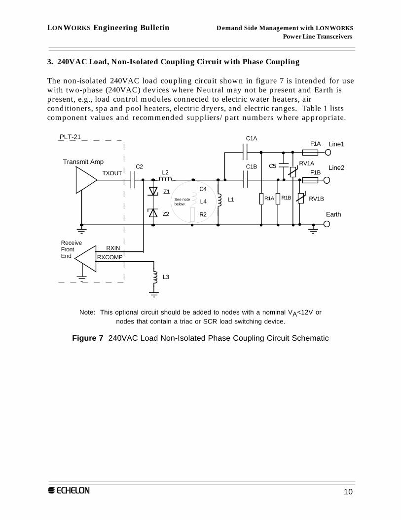
3. 240VAC Load, Non-Isolated Coupling Circuit with Phase Coupling
The non-isolated 240VAC load coupling circuit shown in figure 7 is intended for usewith two-phase (240VAC) devices where Neutral may not be present and Earth ispresent, e.g., load control modules connected to electric water heaters, airconditioners, spa and pool heaters, electric dryers, and electric ranges. Table 1 listscomponent values and recommended suppliers/part numbers where appropriate.
Transmit Amp
ReceiveFrontEnd
PLT-21
C1BC2
L1
L2TXOUT
RXIN
RXCOMP
L3
Earth
Z1
Z2
C1ALine1
R1A
F1A
F1B
R1BL4
C4
R2
Line2C5 RV1A
RV1BSee note below.
Note: This optional circuit should be added to nodes with a nominal VA<12V ornodes that contain a triac or SCR load switching device.
Figure 7 240VAC Load Non-Isolated Phase Coupling Circuit Schematic
LONWORKS Engineering Bulletin Demand Side Management with LONWORKS Power Line Transceivers
11
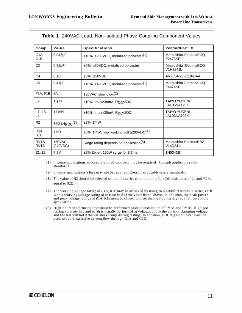
Table 1 240VAC Load, Non-Isolated Phase Coupling Component Values
Comp Value Specifications Vendor/Part #
C1A,C1B
0.047µF ±10%, ≥250VDC, metalized polyester(1) Matsushita Electric/ECQ-E2473KF
C2 0.82µF ±5%, ≥50VDC, metalized polyester Matsushita Electric/ECQ-V1H824JL
C4 0.1µF ±5%, ≥50VDC AVX /SR205C104JAA
C5 0.47µF ±10%, ≥400VDC, metalized polyester(1) Matsushita Electric/ECQ-E4474KF
F1A, F1B 6A 125VAC, slow blow(2)
L2 12µH ±10%, Imax≥30mA, RDC≤50Ω TAIYO YUDEN/LAL05NA120K
L1, L3,L4
1.0mH ±10%, Imax≥30mA, RDC≤50Ω TAIYO YUDEN/LAL03NA102K
R2 82Ω-L4RDC(3) ±5%, 1/4W
R1A,R1B
1MΩ ±5%, 1/4W, max working volt ≥200VDC(4)
RV1A,RV1B
150VAC(240VDC)
Surge rating depends on application(5) Matsushita Electric/ERZ-V14D241
Z1, Z2 7.5V ±5% Zener, 180W surge for 8.3ms 1N5343B
(1) In some applications an X2 safety rated capacitor may be required. Consult applicable safetystandards.
(2) In some applications a fuse may not be required. Consult applicable safety standards.
(3) The value of R2 should be selected so that the series combination of the DC resistance of L4 and R2 isequal to 82Ω.
(4) The working voltage rating of R1A, R1B may be achieved by using two 470kΩ resistors in series, eachwith a working voltage rating of at least half of the value listed above. In addition, the peak powerand peak voltage ratings of R1A, R1B must be chosen to meet the high-pot testing requirements of theapplication.
(5) High-pot manufacturing tests must be performed prior to installation of RV1A and RV1B. High-pottesting between line and earth is usually performed at voltages above the varistor clamping voltage,and the test will fail if the varistors clamp during testing. In addition, a DC high-pot tester must beused to avoid excessive current flow through C1A and C1B.
LONWORKS Engineering Bulletin Demand Side Management with LONWORKS Power Line Transceivers
12
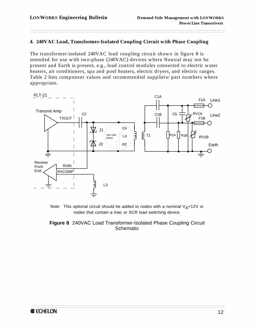
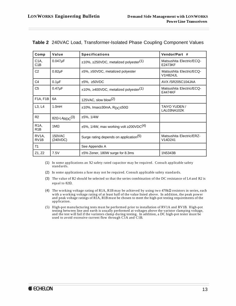
4. 240VAC Load, Transformer-Isolated Coupling Circuit with Phase Coupling
The transformer-isolated 240VAC load coupling circuit shown in figure 8 isintended for use with two-phase (240VAC) devices where Neutral may not bepresent and Earth is present, e.g., load control modules connected to electric waterheaters, air conditioners, spa and pool heaters, electric dryers, and electric ranges.Table 2 lists component values and recommended suppliers/part numbers whereappropriate.
Transmit Amp
ReceiveFrontEnd
PLT-21
C2TXOUT
RXIN
RXCOMP
L3
Z1
Z2
L4
C4
R2
See note below.
C1B
T1
Earth
C1ALine1
R1A
F1A
F1B
R1B
Line2C5 RV1A
RV1B
Note: This optional circuit should be added to nodes with a nominal VA<12V ornodes that contain a triac or SCR load switching device.
Figure 8 240VAC Load Transformer-Isolated Phase Coupling CircuitSchematic
LONWORKS Engineering Bulletin Demand Side Management with LONWORKS Power Line Transceivers
13
Table 2 240VAC Load, Transformer-Isolated Phase Coupling Component Values
Comp Value Specifications Vendor/Part #
C1A,C1B
0.047µF ±10%, ≥250VDC, metalized polyester(1) Matsushita Electric/ECQ-E2473KF
C2 0.82µF ±5%, ≥50VDC, metalized polyester Matsushita Electric/ECQ-V1H824JL
C4 0.1µF ±5%, ≥50VDC AVX /SR205C104JAA
C5 0.47µF ±10%, ≥400VDC, metalized polyester(1) Matsushita Electric/ECQ-E4474KF
F1A, F1B 6A 125VAC, slow blow(2)
L3, L4 1.0mH ±10%, Imax≥30mA, RDC≤50Ω TAIYO YUDEN /LAL03NA102K
R2 82Ω-L4RDC(3) ±5%, 1/4W
R1A,R1B
1MΩ ±5%, 1/4W, max working volt ≥200VDC(4)
RV1A,RV1B
150VAC(240VDC)
Surge rating depends on application(5) Matsushita Electric/ERZ-V14D241
T1 See Appendix A
Z1, Z2 7.5V ±5% Zener, 180W surge for 8.3ms 1N5343B
(1) In some applications an X2 safety rated capacitor may be required. Consult applicable safetystandards.
(2) In some applications a fuse may not be required. Consult applicable safety standards.
(3) The value of R2 should be selected so that the series combination of the DC resistance of L4 and R2 isequal to 82Ω.
(4) The working voltage rating of R1A, R1B may be achieved by using two 470kΩ resistors in series, eachwith a working voltage rating of at least half of the value listed above. In addition, the peak powerand peak voltage ratings of R1A, R1B must be chosen to meet the high-pot testing requirements of theapplication.
(5) High-pot manufacturing tests must be performed prior to installation of RV1A and RV1B. High-pottesting between line and earth is usually performed at voltages above the varistor clamping voltage,and the test will fail if the varistors clamp during testing. In addition, a DC high-pot tester must beused to avoid excessive current flow through C1A and C1B.
LONWORKS Engineering Bulletin Demand Side Management with LONWORKS Power Line Transceivers
14
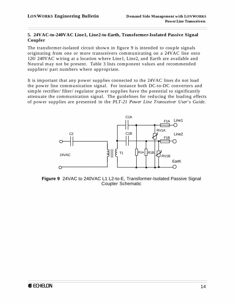
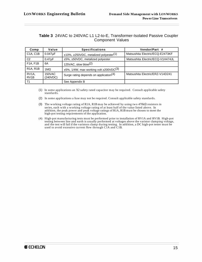
5. 24VAC-to-240VAC Line1, Line2-to-Earth, Transformer-Isolated Passive SignalCoupler
The transformer-isolated circuit shown in figure 9 is intended to couple signalsoriginating from one or more transceivers communicating on a 24VAC line onto120/240VAC wiring at a location where Line1, Line2, and Earth are available andNeutral may not be present. Table 3 lists component values and recommendedsuppliers/part numbers where appropriate.
It is important that any power supplies connected to the 24VAC lines do not loadthe power line communication signal. For instance both DC-to-DC converters andsimple rectifier/filter/regulator power supplies have the potential to significantlyattenuate the communication signal. The guidelines for reducing the loading effectsof power supplies are presented in the PLT-21 Power Line Transceiver User's Guide.
C1B
T1
Earth
C1ALine1
R1A
F1A
F1B
R1B
Line2RV1A
RV1B
C2
24VAC
Figure 9 24VAC to 240VAC L1 L2-to-E, Transformer-Isolated Passive SignalCoupler Schematic
LONWORKS Engineering Bulletin Demand Side Management with LONWORKS Power Line Transceivers
15
Table 3 24VAC to 240VAC L1 L2-to-E, Transformer-Isolated Passive CouplerComponent Values
Comp Value Specifications Vendor/Part #C1A, C1B 0.047µF ±10%, ≥250VDC, metalized polyester(1) Matsushita Electric/ECQ-E2473KF
C2 0.47µF ±5%, ≥50VDC, metalized polyester Matsushita Electric/ECQ-V1H474JLF1A, F1B 6A 125VAC, slow blow(2)
R1A, R1B 1MΩ ±5%, 1/4W, max working volt ≥200VDC(3)
RV1A,RV1B
150VAC(240VDC)
Surge rating depends on application(4) Matsushita Electric/ERZ-V14D241
T1 See Appendix B
(1) In some applications an X2 safety rated capacitor may be required. Consult applicable safetystandards.
(2) In some applications a fuse may not be required. Consult applicable safety standards.
(3) The working voltage rating of R1A, R1B may be achieved by using two 470kΩ resistors inseries, each with a working voltage rating of at least half of the value listed above. Inaddition, the peak power and peak voltage ratings of R1A, R1B must be chosen to meet thehigh-pot testing requirements of the application.
(4) High-pot manufacturing tests must be performed prior to installation of RV1A and RV1B. High-pottesting between line and earth is usually performed at voltages above the varistor clamping voltage,and the test will fail if the varistors clamp during testing. In addition, a DC high-pot tester must beused to avoid excessive current flow through C1A and C1B.
LONWORKS Engineering Bulletin Demand Side Management with LONWORKS Power Line Transceivers
16
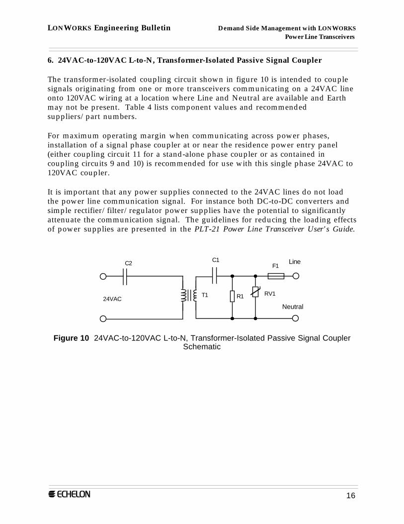
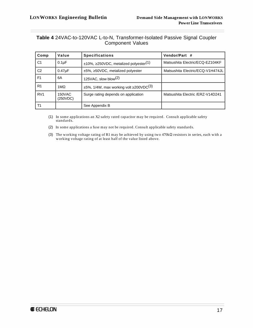
6. 24VAC-to-120VAC L-to-N, Transformer-Isolated Passive Signal Coupler
The transformer-isolated coupling circuit shown in figure 10 is intended to couplesignals originating from one or more transceivers communicating on a 24VAC lineonto 120VAC wiring at a location where Line and Neutral are available and Earthmay not be present. Table 4 lists component values and recommendedsuppliers/part numbers.
For maximum operating margin when communicating across power phases,installation of a signal phase coupler at or near the residence power entry panel(either coupling circuit 11 for a stand-alone phase coupler or as contained incoupling circuits 9 and 10) is recommended for use with this single phase 24VAC to120VAC coupler.
It is important that any power supplies connected to the 24VAC lines do not loadthe power line communication signal. For instance both DC-to-DC converters andsimple rectifier/filter/regulator power supplies have the potential to significantlyattenuate the communication signal. The guidelines for reducing the loading effectsof power supplies are presented in the PLT-21 Power Line Transceiver User's Guide.
C1C2
T1
Line
Neutral
F1
R124VACRV1
Figure 10 24VAC-to-120VAC L-to-N, Transformer-Isolated Passive Signal CouplerSchematic
LONWORKS Engineering Bulletin Demand Side Management with LONWORKS Power Line Transceivers
17
Table 4 24VAC-to-120VAC L-to-N, Transformer-Isolated Passive Signal CouplerComponent Values
Comp Value Specifications Vendor/Part #
C1 0.1µF ±10%, ≥250VDC, metalized polyester(1) Matsushita Electric/ECQ-EZ104KF
C2 0.47µF ±5%, ≥50VDC, metalized polyester Matsushita Electric/ECQ-V1H474JL
F1 6A 125VAC, slow blow(2)
R1 1MΩ ±5%, 1/4W, max working volt ≥200VDC(3)
RV1 150VAC(250VDC)
Surge rating depends on application Matsushita Electric /ERZ-V14D241
T1 See Appendix B
(1) In some applications an X2 safety rated capacitor may be required. Consult applicable safetystandards.
(2) In some applications a fuse may not be required. Consult applicable safety standards.
(3) The working voltage rating of R1 may be achieved by using two 470kΩ resistors in series, each with aworking voltage rating of at least half of the value listed above.
LONWORKS Engineering Bulletin Demand Side Management with LONWORKS Power Line Transceivers
18
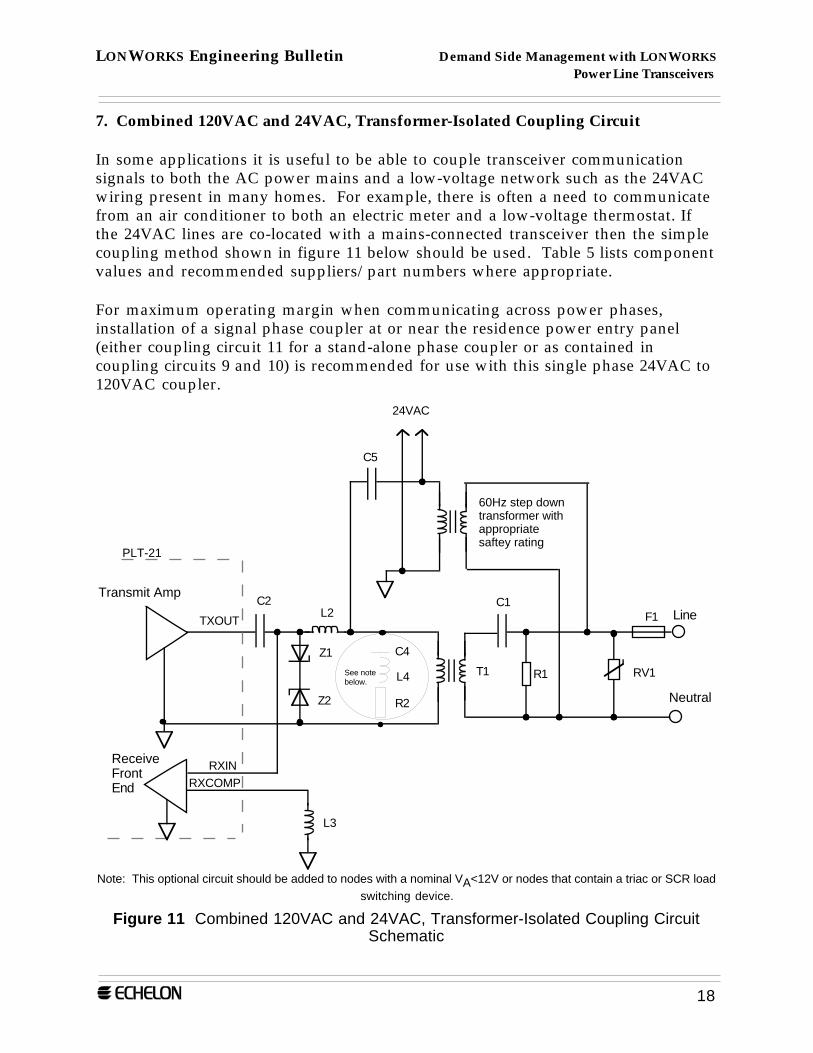
7. Combined 120VAC and 24VAC, Transformer-Isolated Coupling Circuit
In some applications it is useful to be able to couple transceiver communicationsignals to both the AC power mains and a low-voltage network such as the 24VACwiring present in many homes. For example, there is often a need to communicatefrom an air conditioner to both an electric meter and a low-voltage thermostat. Ifthe 24VAC lines are co-located with a mains-connected transceiver then the simplecoupling method shown in figure 11 below should be used. Table 5 lists componentvalues and recommended suppliers/part numbers where appropriate.
For maximum operating margin when communicating across power phases,installation of a signal phase coupler at or near the residence power entry panel(either coupling circuit 11 for a stand-alone phase coupler or as contained incoupling circuits 9 and 10) is recommended for use with this single phase 24VAC to120VAC coupler.
L4
C4
R2
See note below.
Transmit Amp
ReceiveFrontEnd
PLT-21
C1C2
T1
L2TXOUT
RXINRXCOMP
L3
Line
Neutral
Z1
Z2
C5
R1
F1
RV1
24VAC
60Hz step down transformer with appropriate saftey rating
Note: This optional circuit should be added to nodes with a nominal VA<12V or nodes that contain a triac or SCR loadswitching device.
Figure 11 Combined 120VAC and 24VAC, Transformer-Isolated Coupling CircuitSchematic
LONWORKS Engineering Bulletin Demand Side Management with LONWORKS Power Line Transceivers
19
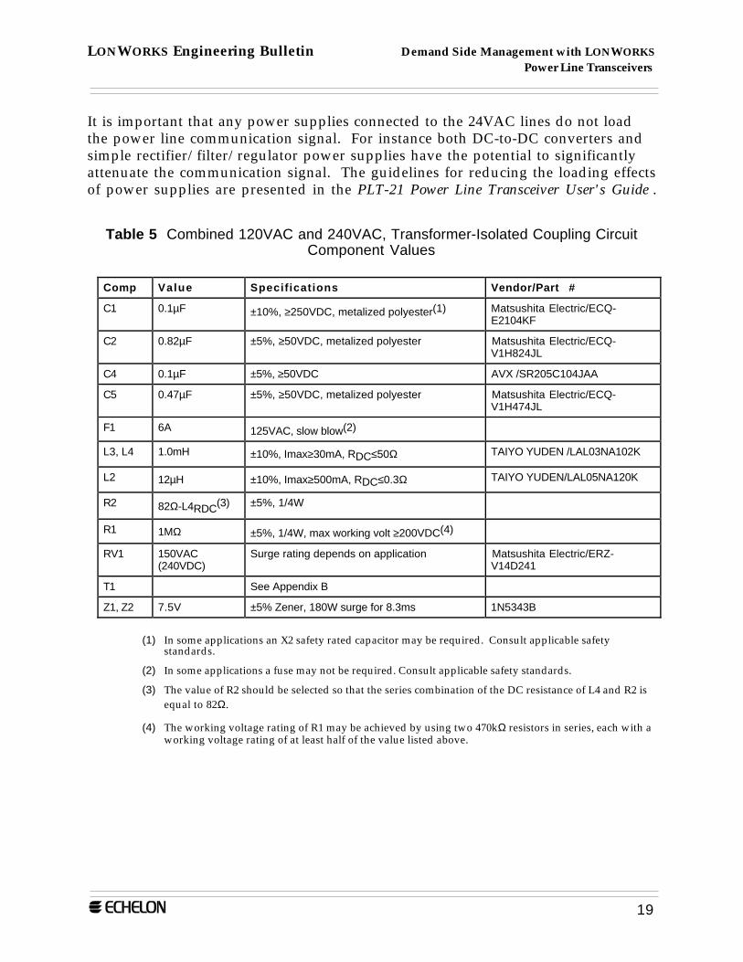
It is important that any power supplies connected to the 24VAC lines do not loadthe power line communication signal. For instance both DC-to-DC converters andsimple rectifier/filter/regulator power supplies have the potential to significantlyattenuate the communication signal. The guidelines for reducing the loading effectsof power supplies are presented in the PLT-21 Power Line Transceiver User's Guide .
Table 5 Combined 120VAC and 240VAC, Transformer-Isolated Coupling CircuitComponent Values
Comp Value Specifications Vendor/Part #
C1 0.1µF ±10%, ≥250VDC, metalized polyester(1) Matsushita Electric/ECQ-E2104KF
C2 0.82µF ±5%, ≥50VDC, metalized polyester Matsushita Electric/ECQ-V1H824JL
C4 0.1µF ±5%, ≥50VDC AVX /SR205C104JAA
C5 0.47µF ±5%, ≥50VDC, metalized polyester Matsushita Electric/ECQ-V1H474JL
F1 6A 125VAC, slow blow(2)
L3, L4 1.0mH ±10%, Imax≥30mA, RDC≤50Ω TAIYO YUDEN /LAL03NA102K
L2 12µH ±10%, Imax≥500mA, RDC≤0.3Ω TAIYO YUDEN/LAL05NA120K
R2 82Ω-L4RDC(3) ±5%, 1/4W
R1 1MΩ ±5%, 1/4W, max working volt ≥200VDC(4)
RV1 150VAC(240VDC)
Surge rating depends on application Matsushita Electric/ERZ-V14D241
T1 See Appendix B
Z1, Z2 7.5V ±5% Zener, 180W surge for 8.3ms 1N5343B
(1) In some applications an X2 safety rated capacitor may be required. Consult applicable safetystandards.
(2) In some applications a fuse may not be required. Consult applicable safety standards.
(3) The value of R2 should be selected so that the series combination of the DC resistance of L4 and R2 isequal to 82Ω.
(4) The working voltage rating of R1 may be achieved by using two 470kΩ resistors in series, each with aworking voltage rating of at least half of the value listed above.
LONWORKS Engineering Bulletin Demand Side Management with LONWORKS Power Line Transceivers
20
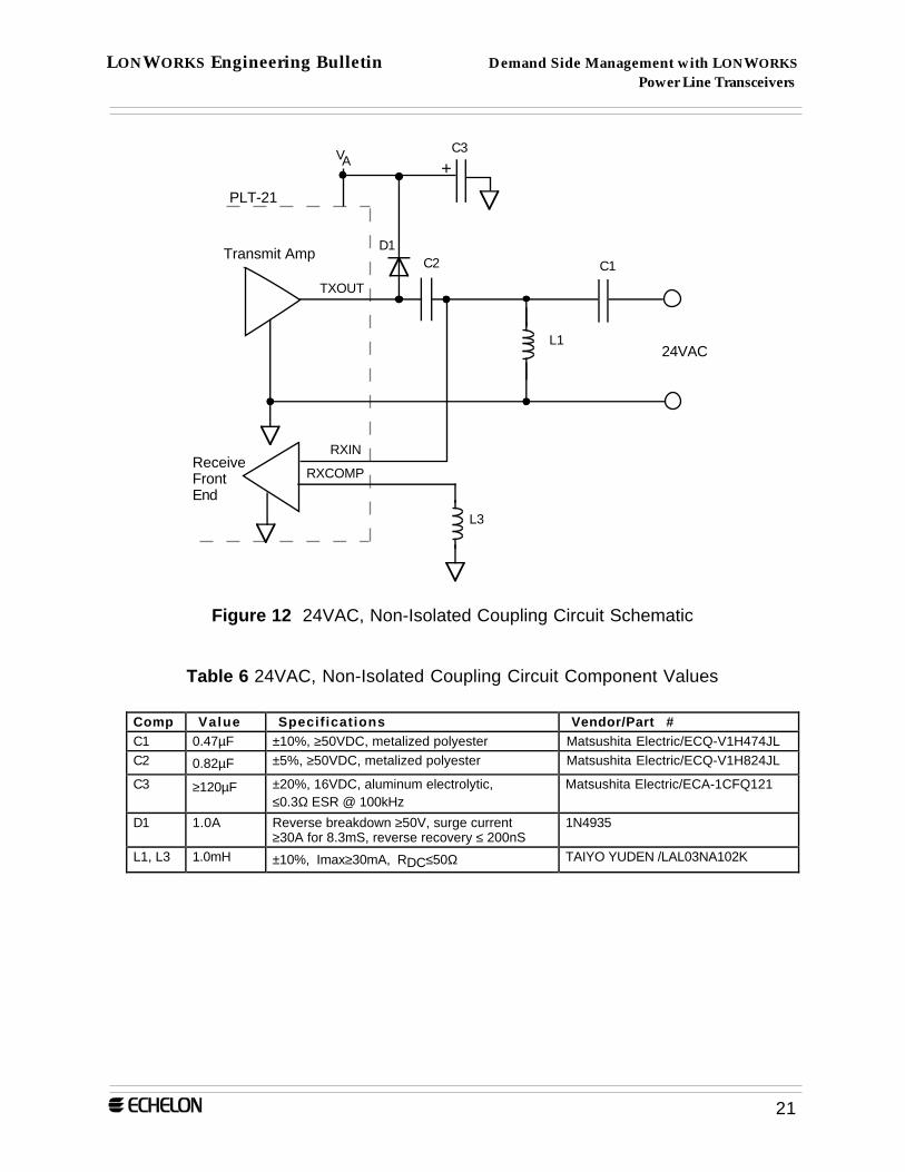
8. 24VAC, Non-Isolated Coupling Circuit
The non-isolated, 24VAC coupling circuit shown in figure 12 is intended forcoupling the transceiver to existing, low-voltage (24VAC) wiring within a house.Typically a passive coupler is used to couple communications signals between thelow-voltage, 24VAC wiring and the 120/240VAC wiring elsewhere in the house (seecoupling circuit 6). Unlike the other coupling circuits presented in this document,the non-isolated, 24VAC coupling circuit does not use resonant coupling and hasbeen simplified considerably to reflect the less demanding, low-voltageenvironment. Table 6 lists component values and recommended suppliers/partnumbers where appropriate.
Care must be taken to ensure that power supplies connected to the 24VAC lines donot load the PLT-21 communications signal. For example, both DC-to-DCconverters and simple rectifier/filter/regulator power supplies have the potential tosignificantly attenuate the PLT-21 communications signal. The guidelines forreducing the loading effects of power supplies are presented in Chapter 5 of the PLT-21 Power Line Transceiver User's Guide.
It is assumed that nodes communicating on the 24VAC lines are powered from the24VAC line and are floating.
LONWORKS Engineering Bulletin Demand Side Management with LONWORKS Power Line Transceivers
21
PLT-21
VAC3
+
Transmit Amp
ReceiveFrontEnd
C1C2
L1
TXOUT
RXIN
RXCOMP
L3
24VAC
D1
Figure 12 24VAC, Non-Isolated Coupling Circuit Schematic
Table 6 24VAC, Non-Isolated Coupling Circuit Component Values
Comp Value Specifications Vendor/Part #C1 0.47µF ±10%, ≥50VDC, metalized polyester Matsushita Electric/ECQ-V1H474JLC2 0.82µF ±5%, ≥50VDC, metalized polyester Matsushita Electric/ECQ-V1H824JL
C3 ≥120µF ±20%, 16VDC, aluminum electrolytic,≤0.3Ω ESR @ 100kHz
Matsushita Electric/ECA-1CFQ121
D1 1.0A Reverse breakdown ≥50V, surge current≥30A for 8.3mS, reverse recovery ≤ 200nS
1N4935
L1, L3 1.0mH ±10%, Imax≥30mA, RDC≤50Ω TAIYO YUDEN /LAL03NA102K

LONWORKS Engineering Bulletin Demand Side Management with LONWORKS Power Line Transceivers
22
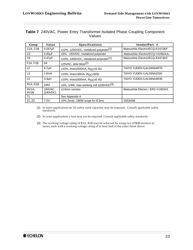
9. 240VAC, Power Entry Transformer-Isolated Coupling Circuit with PhaseCoupling
The transformer-isolated, power entry coupling circuit shown in figure 13 is intendedfor use close to the power entry and main circuit breaker panel of a house. Typicallythis circuit would be installed in or next to an electrical meter. Included in the circuit isphase coupling between Line1 and Line2. Table 7 lists component values andrecommended suppliers/part numbers where appropriate.
Transmit Amp
ReceiveFrontEnd
PLT-21
C1BC2
T1
L2TXOUT
RXIN
RXCOMP
L3
Line2
Neutral
Z1
Z2
C1ALine1
R1A
RV1A
F1A
F1B
RV1B
L5
C5
R1B
Figure 13 240VAC, Power Entry Transformer-Isolated Phase Coupling Schematic
LONWORKS Engineering Bulletin Demand Side Management with LONWORKS Power Line Transceivers
23
Table 7 240VAC, Power Entry Transformer-Isolated Phase Coupling ComponentValues
Comp Value Specifications Vendor/Part #C1A, C1B 0.047µF ±10%, ≥250VDC, metalized polyester(1) Matsushita Electric/ECQ-E2473KF
C2 0.82µF ±5%, ≥50VDC, metalized polyester Matsushita Electric/ECQ-V1H824JLC5 0.47µF ±10%, ≥400VDC, metalized polyester(1) Matsushita Electric/ECQ-E4474KF
F1A, F1B 6A 125VAC, slow blow(2)
L2 4.7µH ±10%, Imax≥500mA, RDC≤0.4Ω TAIYO YUDEN /LAL04NA4R7K
L3 1.0mH ±10%, Imax≥30mA, RDC≤50Ω TAIYO YUDEN /LAL03NA102K
L5 3.3µH ±10%, Imax≥500mA, RDC≤0.4Ω TAIYO YUDEN /LAL04NA3R3K
R1A, R1B 1MΩ ±5%, 1/4W, max working volt ≥200VDC(3)
RV1A,RV1B
150VAC(240VDC)
≥14mm varistor Matsushita Electric / ERZ-V14D241
T1 See Appendix AZ1, Z2 7.5V ±5% Zener, 180W surge for 8.3ms 1N5343B
(1) In some applications an X2 safety rated capacitor may be required. Consult applicable safetystandards.
(2) In some applications a fuse may not be required. Consult applicable safety standards.
(3) The working voltage rating of R1A, R1B may be achieved by using two 470kΩ resistors inseries, each with a working voltage rating of at least half of the value listed above.

LONWORKS Engineering Bulletin Demand Side Management with LONWORKS Power Line Transceivers
24
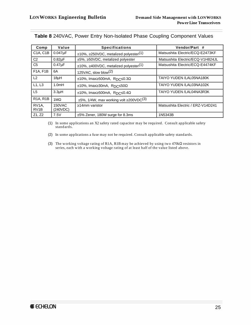
10. 240VAC, Power Entry Non-Isolated Coupling Circuit with Phase Coupling
The non-isolated, power entry coupling circuit shown in figure 14 is intended foruse close to the power entry and main circuit breaker panel of a house. Typicallythis circuit would be installed in an electrical meter. Included in the circuit is phasecoupling between Line1 and Line2. Table 8 lists component values andrecommended suppliers/part numbers where appropriate.
Transmit Amp
ReceiveFrontEnd
PLT-21
C1BC2
L1
L2TXOUT
RXIN
RXCOMP
L3
Line2
Neutral
Z1
Z2
C1ALine1
R1A
RV1A
F1A
F1B
R1BRV1B
L5
C5
Figure 14 240VAC, Power Entry Non-Isolated Phase Coupling Schematic
LONWORKS Engineering Bulletin Demand Side Management with LONWORKS Power Line Transceivers
25
Table 8 240VAC, Power Entry Non-Isolated Phase Coupling Component Values
Comp Value Specifications Vendor/Part #C1A, C1B 0.047µF ±10%, ≥250VDC, metalized polyester(1) Matsushita Electric/ECQ-E2473KF
C2 0.82µF ±5%, ≥50VDC, metalized polyester Matsushita Electric/ECQ-V1H824JLC5 0.47µF ±10%, ≥400VDC, metalized polyester(1) Matsushita Electric/ECQ-E4474KF
F1A, F1B 6A 125VAC, slow blow(2)
L2 18µH ±10%, Imax≥500mA, RDC≤0.3Ω TAIYO YUDEN /LAL05NA180K
L1, L3 1.0mH ±10%, Imax≥30mA, RDC≤50Ω TAIYO YUDEN /LAL03NA102K
L5 3.3µH ±10%, Imax≥500mA, RDC≤0.4Ω TAIYO YUDEN /LAL04NA3R3K
R1A, R1B 1MΩ ±5%, 1/4W, max working volt ≥200VDC(3)
RV1A,RV1B
150VAC(240VDC)
≥14mm varistor Matsushita Electric / ERZ-V14D241
Z1, Z2 7.5V ±5% Zener, 180W surge for 8.3ms 1N5343B
(1) In some applications an X2 safety rated capacitor may be required. Consult applicable safetystandards.
(2) In some applications a fuse may not be required. Consult applicable safety standards.
(3) The working voltage rating of R1A, R1B may be achieved by using two 470kΩ resistors inseries, each with a working voltage rating of at least half of the value listed above.

LONWORKS Engineering Bulletin Demand Side Management with LONWORKS Power Line Transceivers
26
11. Line-to-Line Power Entry Passive Signal Coupler
The circuit shown in figure 15 is intended to couple communication signals fromLine1 to Line2, and may be installed close to the power entry and main circuitbreaker panel of a house for improved communication margin. Table 9 listscomponent values and recommended suppliers/part numbers where appropriate.
C1L1
Line1F1Line2
Figure 15 L-to-L Power Entry Passive Signal Coupler Schematic

LONWORKS Engineering Bulletin Demand Side Management with LONWORKS Power Line Transceivers
27
Table 9 L-to-L Power Entry Passive Signal Coupler Component Values
Comp Value Specifications Vendor/Part #C1 0.47µF ±10%, ≥400VDC, metalized polyester(1) Matsushita Electric/ECQ-E4474KF
F1 min 3.0A 250VAC, slow blow(2)
L1 3.3µH ±10%, Imax≥500mA, RDC≤0.4Ω TAIYO YUDEN/LAL04NA3R3K
(1) In some applications an X2 safety rated capacitor may be required. Consult applicable safetystandards.
(2) In some applications a fuse may not be required. Consult applicable safety standards.
LONWORKS Engineering Bulletin Demand Side Management with LONWORKS Power Line Transceivers
28
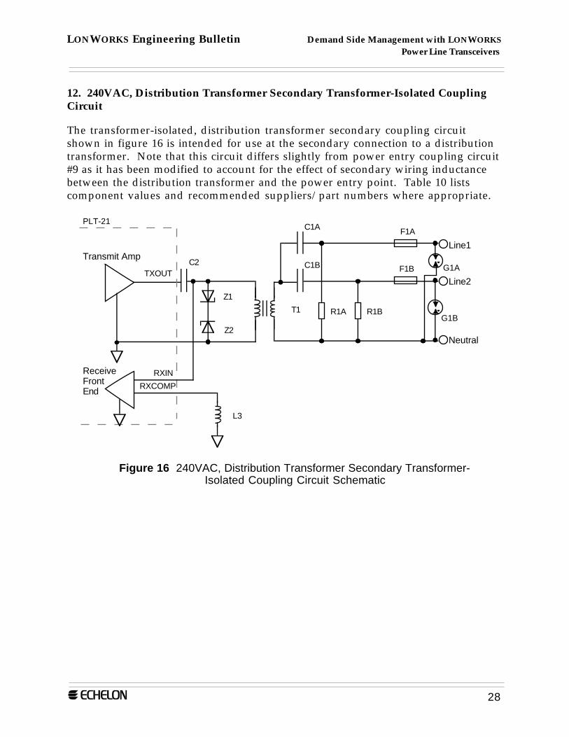
12. 240VAC, Distribution Transformer Secondary Transformer-Isolated CouplingCircuit
The transformer-isolated, distribution transformer secondary coupling circuitshown in figure 16 is intended for use at the secondary connection to a distributiontransformer. Note that this circuit differs slightly from power entry coupling circuit#9 as it has been modified to account for the effect of secondary wiring inductancebetween the distribution transformer and the power entry point. Table 10 listscomponent values and recommended suppliers/part numbers where appropriate.
Transmit Amp
ReceiveFrontEnd
PLT-21
C1BC2
T1
TXOUT
RXIN
RXCOMP
L3
Z1
Z2
C1A
R1A R1B
Line2
Neutral
Line1
F1A
F1B G1A
G1B
Figure 16 240VAC, Distribution Transformer Secondary Transformer-Isolated Coupling Circuit Schematic

LONWORKS Engineering Bulletin Demand Side Management with LONWORKS Power Line Transceivers
29
Table 10 240VAC, Distribution Transformer Secondary Transformer-Isolated CouplingCircuit Component Values
Comp Value Specifications Vendor/Part #C1A, C1B 0.047µF ±10%, ≥250VAC, X2 type Nissi Denki/Arcotronics
R40473K275XXXXC2 0.82µF ±5%, ≥50VDC, metalized polyester Matsushita Electric/ECQ-V1H824JLF1A, F1B 6A 125VAC, slow blow(1)
L3 1.0mH ±10%, Imax≥30mA, RDC≤50Ω TAIYO YUDEN /LAL03NA102K
R1A, R1B 1MΩ ±5%, 1/4W, max working volt ≥200VDC(2)
T1 See Appendix AZ1, Z2 7.5V ±5% Zener, 180W surge for 8.3ms 1N5343BG1A, G1B 120VAC AC gas discharge tube CPClare/AC120L
(1) In some applications a fuse may not be required. Consult applicable safety standards.
(2) The working voltage rating of R1A, R1B may be achieved by using two 470kΩ resistors inseries, each with a working voltage rating of at least half of the value listed above.
LONWORKS Engineering Bulletin Demand Side Management with LONWORKS Power Line Transceivers
30
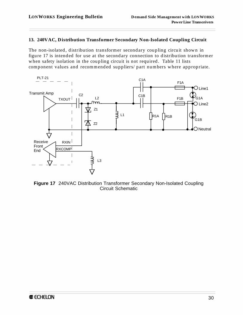
13. 240VAC, Distribution Transformer Secondary Non-Isolated Coupling Circuit
The non-isolated, distribution transformer secondary coupling circuit shown infigure 17 is intended for use at the secondary connection to distribution transformerwhen safety isolation in the coupling circuit is not required. Table 11 listscomponent values and recommended suppliers/part numbers where appropriate.
Line2
Neutral
Line1
F1A
F1B G1A
G1B
Transmit Amp
ReceiveFrontEnd
PLT-21
C1BC2
L1
L2TXOUT
RXIN
RXCOMP
L3
Z1
Z2
C1A
R1A R1B
Figure 17 240VAC Distribution Transformer Secondary Non-Isolated CouplingCircuit Schematic

LONWORKS Engineering Bulletin Demand Side Management with LONWORKS Power Line Transceivers
31
Table 11 240VAC, Distribution Transformer Secondary Non-Isolated Coupling CircuitComponent Values
Comp Value Specifications Vendor/Part #C1A, C1B 0.047µF ±10%, ≥250VAC, X2 type Nissi Denki/Arcotronics
R40473K275XXXXC2 0.82µF ±5%, ≥50VDC, metalized polyester Matsushita Electric/ECQ-V1H824JLF1A, F1B 6A 125VAC, slow blow(1)
L2 12µH ±10%, Imax≥500mA, RDC≤0.3Ω TAIYO YUDEN /LAL05NA120K
L1, L3 1.0mH ±10%, Imax≥30mA, RDC≤50Ω TAIYO YUDEN /LAL03NA102K
R1A, R1B 1MΩ ±5%, 1/4W, max working volt ≥200VDC(2)
Z1, Z2 7.5V ±5% Zener, 180W surge for 8.3ms 1N5343BG1A, G1B 120VAC AC gas discharge tube CPClare/AC120L
(1) In some applications a fuse may not be required. Consult applicable safety standards.
(2) The working voltage rating of R1A, R1B may be achieved by using two 470kΩ resistors inseries, each with a working voltage rating of at least half of the value listed above.

LONWORKS Engineering Bulletin Demand Side Management with LONWORKS Power Line Transceivers
32
Appendix A — PLT-21 Transceiver Isolation TransformerSpecifications for 12µH of Series Leakage Inductance
This appendix provides a schematic, specifications, and supplier information for aPLT-21 transceiver isolation transformer which includes 12µH of series leakageinductance.
PLT-21 Transceiver Isolation Transformer Schematic
1
2
3
4
Primary Secondary
PLT-21 Transceiver Isolation Transformer Electrical Specifications
Below are specifications for the PLT-21 Transceiver Isolation Transformer whichincludes 12µH of series leakage inductance.
Parameter Min Typ Max Units
Turns Ratio (1-2) : (3-4) 1.0
DC Resistance
1-23-4
0.200.20
OhmOhm
Magnetizing Inductance 1-2 Dry, @100kHz, 1Vrms
0.75 1.0 1.25 mH
Magnetizing Inductance 1-2, Wet, @100kHz, 1Vrms, plus 15mADC
0.75 mH
Leakage Inductance 1-2(3-4 shorted) @100kHz, 1Vrms
10.8 12.0 13.2 µH
Winding Capacitance 1-2 30 pF
Winding to Winding Capacitance1-2 shorted to 3-4 shorted
30 pF
LONWORKS Engineering Bulletin Demand Side Management with LONWORKS Power Line Transceivers
33
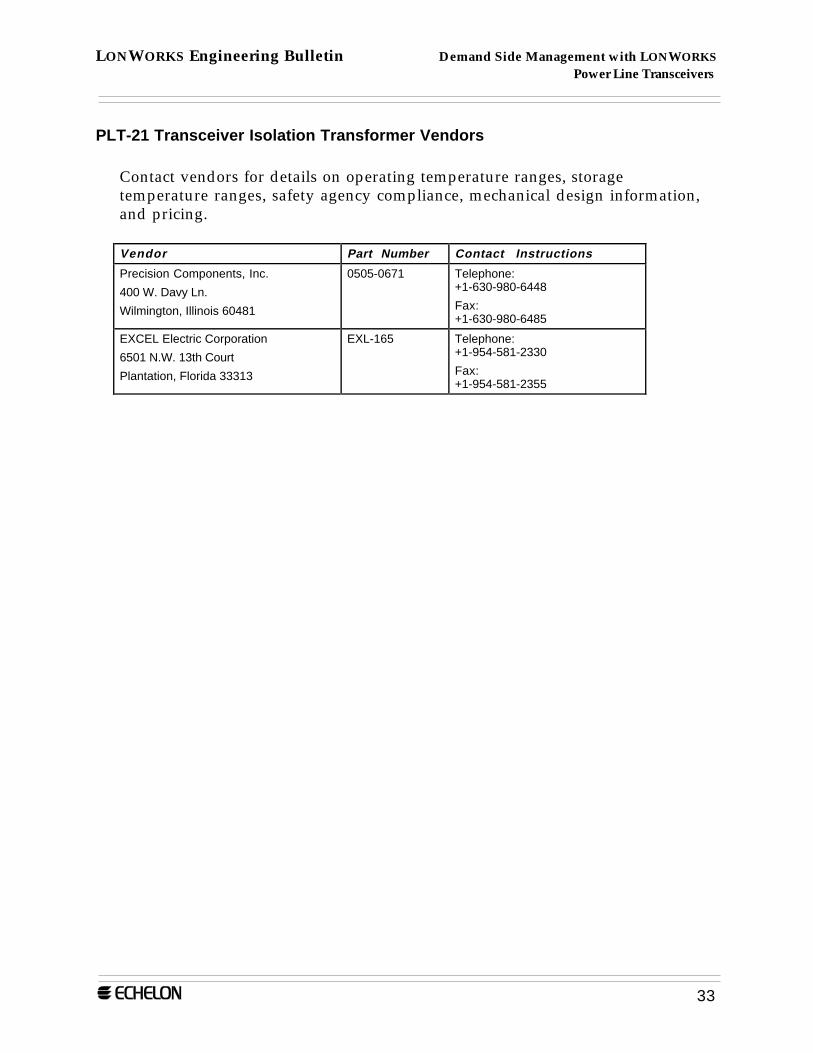
PLT-21 Transceiver Isolation Transformer Vendors
Contact vendors for details on operating temperature ranges, storagetemperature ranges, safety agency compliance, mechanical design information,and pricing.
Vendor Part Number Contact Instructions
Precision Components, Inc.
400 W. Davy Ln.
Wilmington, Illinois 60481
0505-0671 Telephone:+1-630-980-6448
Fax:+1-630-980-6485
EXCEL Electric Corporation
6501 N.W. 13th Court
Plantation, Florida 33313
EXL-165 Telephone:+1-954-581-2330
Fax:+1-954-581-2355
LONWORKS Engineering Bulletin Demand Side Management with LONWORKS Power Line Transceivers
34
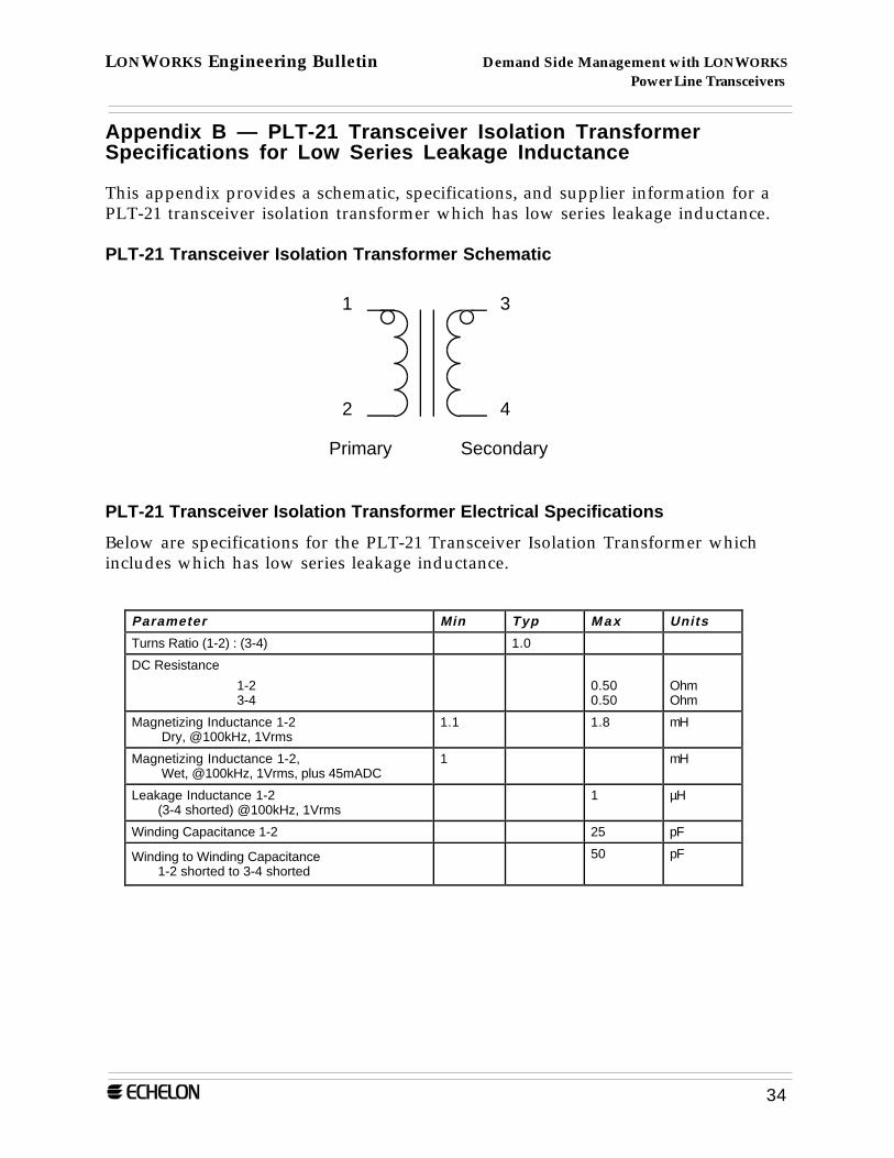
Appendix B — PLT-21 Transceiver Isolation TransformerSpecifications for Low Series Leakage Inductance
This appendix provides a schematic, specifications, and supplier information for aPLT-21 transceiver isolation transformer which has low series leakage inductance.
PLT-21 Transceiver Isolation Transformer Schematic
1
2
3
4
Primary Secondary
PLT-21 Transceiver Isolation Transformer Electrical Specifications
Below are specifications for the PLT-21 Transceiver Isolation Transformer whichincludes which has low series leakage inductance.
Parameter Min Typ Max Units
Turns Ratio (1-2) : (3-4) 1.0
DC Resistance
1-23-4
0.500.50
OhmOhm
Magnetizing Inductance 1-2 Dry, @100kHz, 1Vrms
1.1 1.8 mH
Magnetizing Inductance 1-2, Wet, @100kHz, 1Vrms, plus 45mADC
1 mH
Leakage Inductance 1-2(3-4 shorted) @100kHz, 1Vrms
1 µH
Winding Capacitance 1-2 25 pF
Winding to Winding Capacitance1-2 shorted to 3-4 shorted
50 pF
LONWORKS Engineering Bulletin Demand Side Management with LONWORKS Power Line Transceivers
35
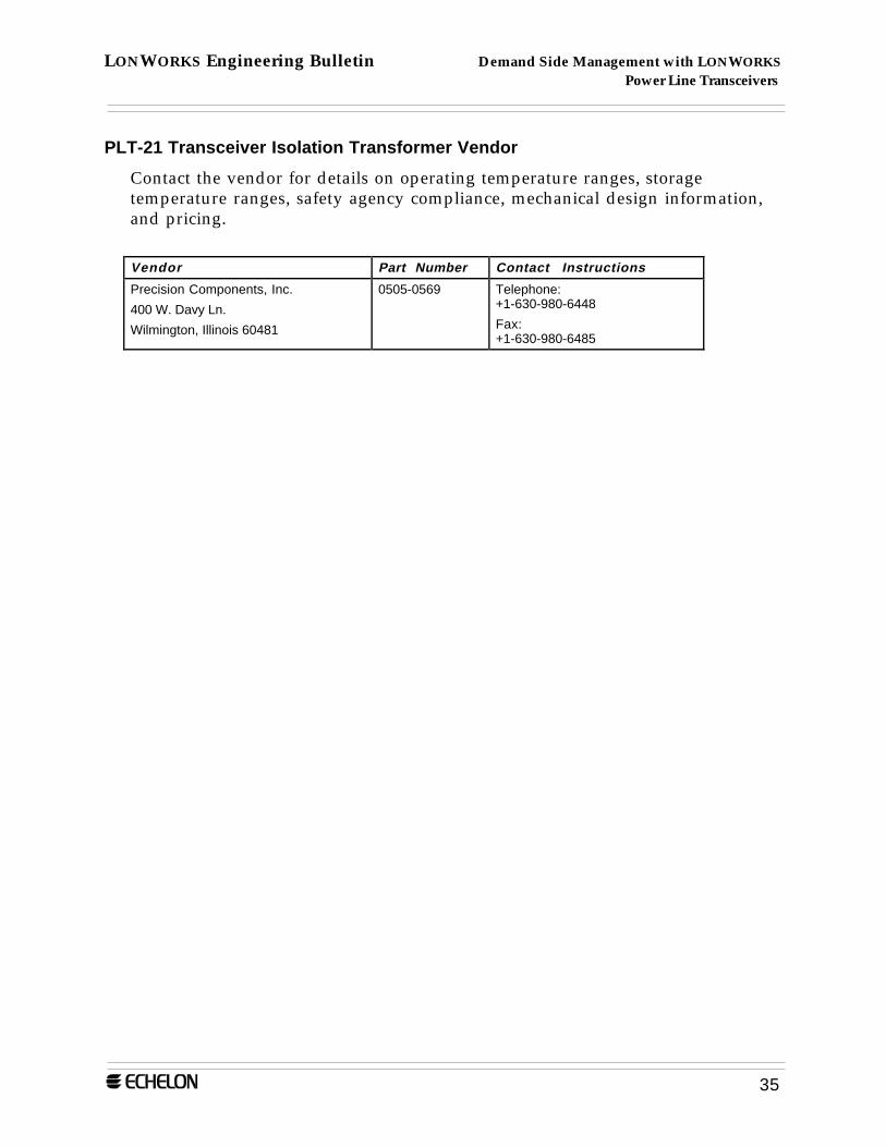
PLT-21 Transceiver Isolation Transformer Vendor
Contact the vendor for details on operating temperature ranges, storagetemperature ranges, safety agency compliance, mechanical design information,and pricing.
Vendor Part Number Contact Instructions
Precision Components, Inc.
400 W. Davy Ln.
Wilmington, Illinois 60481
0505-0569 Telephone:+1-630-980-6448
Fax:+1-630-980-6485

LONWORKS Engineering Bulletin Demand Side Management with LONWORKS Power Line Transceivers
36
Related Documents
Echelon LONWORKS Product Data Book; Echelon
LONWORKS PLT-20 Power Line Transceiver User's Guide; Echelon
LONWORKS PLT-21 Power Line Transceiver User's Guide; Echelon
LONWORKS PLCA-20 Power Line Communication Analyzer User's Guide; Echelon
LONWORKS PLCA-21 Power Line Communication Analyzer User's Guide; Echelon
Centralized Commercial Building Applications with the LONW ORKS PLT-21 PowerLine Transceiver; Echelon
LONW ORKS PLA-21 Power Line Amplifier Specification and User’s Guide
DisclaimerEchelon Corporation assumes no responsibility for any errors contained herein.
No part of this document may be reproduced, translated, or transmitted in any form without permission from Echelon.
Part Number 005-0070-01 Rev. B
© 1996 Echelon Corporation. Echelon, LON,LONWORKS, Neuron, 3150, 3120, LonBuilder,LonTalk, and LonManager are U.S. registeredtrademarks of Echelon Corporation. Some of theLONWORKS products are patented and aresubject to licensing Terms and Conditions. For acomplete explanation, please call 1-800-258-4LON.
Echelon Corporation4015 Miranda AvenuePalo Alto, CA 94304Telephone (415) 855-7400Fax (415) 856-6153
http://www.lonworks.echelon.com
Echelon Europe LtdElsinore House77 Fulham Palace RoadLondon W6 8JAEnglandTelephone +44-181-324-1800Fax +44-181-563-7055
Echelon Japan K.K.Kamino Shoji Bldg. 8F25-13 Higashi-Gotanda 1-chomeShinagawa-ku, Tokyo 141Telephone (03) 3440-7781Fax (03) 3440-7782
Recommended