DATE: 19/12/2014
VERSION: FINAL
AUTHOR(S): R F THOMAS (NXNW), S F SURJA (ARC) & R A BOUKENS (ARC)
REVIEWED BY: M. VERSTEEGDEN (ARC) & I. MÜLLERS (SP)
APPROVED BY: COORDINATOR – ANS VAN DOORMAAL (TNO)
DELIVERABLE REPORT
DELIVERABLE N0: D2.3
DISSEMINATION LEVEL: PUBLIC
TITLE: 1ST
COORDINATED RESILIENT DESIGN OF THE BUILDING
GRANT AGREEMENT NUMBER: 312632
PROJECT TYPE: FP7-SEC-2012.2.1-1 RESILIENCE OF LARGE SCALE URBAN BUILT
INFRASTRUCTURE – CAPABILITY PROJECT
PROJECT ACRONYM: ELASSTIC
PROJECT TITLE: ENHANCED LARGE SCALE ARCHITECTURE WITH SAFETY AND
SECURITY TECHNOLOGIES AND SPECIAL INFORMATION
CAPABILITIES
PROJECT START DATE: 01/05/2013
PROJECT WEBSITE: WWW.ELASSTIC.EU
TECHNICAL COORDINATION TNO (NL) (WWW.TNO.NL)
PROJECT ADMINISTRATION UNIRESEARCH (NL) (WWW.UNIRESEARCH.NL)

D2.3 | 1st Coordinated Resilient Design
FINAL
2
Executive Summary
The aim of Work Package 2 is firstly to create a full design of a safe, secure and resilient, large scale, multifunctional
building complex in order that the ELASSTIC team members can explore and experiment with the various impacts as
a consequence of different catastrophe scenarios. Afterwards, the project can be redesigned taking into account
the analysis data that have been elaborated.
Consequently, the design stages are divided into three parts:
1. BENCHMARK DESIGN - A preliminary design in order that all the ELASSTIC team can validate a certain
architectural approach and also that the whole design team can base their appropriate specialisations,
including structures and building services.
2. 1st
COORDINATED DESIGN – A full conceptual design following the studies of each design team member.
This design will be the basis which be used for testing and experimenting the different hazard scenarios.
3. 1st
INTEGRATED DESIGN – A redesign of the concept design following the integration of the research
analysis made in Work Package n°3.
This report intends to explain and describe the design process carried out for the second stage, the 1st
Coordinated
Design, and in particular the tasks 2.3 and 2.4 in the Description of Works of the ELASSTIC programme.
Keywords: 1st
Coordinated design, 1st
Quantitative Design ELASSTIC programme, The Ribbon, Showcase, BIM
technology,

D2.3 | 1st Coordinated Resilient Design
FINAL
3
Contents
Executive Summary ............................................................................................................................... 2
Contents ................................................................................................................................................ 3
1 Introduction / background ............................................................................................................... 5
1.1 History and Procedure and Continuation ..................................................................................... 5
1.1.1 History ........................................................................................................................ 5
1.1.2 Procedure ................................................................................................................... 5
1.2 Reminder of the Design Process (WP1) ........................................................................................ 6
1.3 Reminder of the Architectural Benchmark Design (WP T2.2.2) ................................................... 6
1.3.1 Project Description ..................................................................................................... 6
2 Research methodology / results ....................................................................................................... 9
2.1 Division into building parts ........................................................................................................... 9
2.2 Architectural Design ................................................................................................................... 10
2.2.1 Ribbon 1: Theatre, Hotel & Housing ......................................................................... 10
2.2.2 Ribbon 2: Offices ....................................................................................................... 12
2.2.3 Ribbon 3: Museum & Commercial retail .................................................................. 13
2.2.4 Ribbon 4: Housing & Commercial retail.................................................................... 14
2.2.5 Ribbon 0: Parking ...................................................................................................... 14
2.3 Structural Design ........................................................................................................................ 16
2.3.1 Structural Introduction: Document goal and structure ............................................ 16
2.3.2 Basic Assumptions .................................................................................................... 16
2.3.2.1 Standards, specifications and guidelines ........................................... 16
2.3.2.2 Partial factors for actions ................................................................... 17
2.3.2.3 ............................................................................................. 17
2.3.3 Material and structural member properties ............................................................ 18
2.3.3.1 self-weight .......................................................................................... 18
2.3.3.2 Material qualities and strength classes .............................................. 18
2.3.3.3 product information ........................................................................... 18
2.3.4 Imposed loads for buildings ...................................................................................... 19
2.3.5 Wind actions ............................................................................................................. 21
2.3.5.1 lay-out and orientation of ELASSTIC buildings ................................... 21
2.3.5.2 calculation method ............................................................................. 22
2.3.5.3 force coefficients ................................................................................ 26
2.3.6 Structural design ....................................................................................................... 27
2.3.6.1 Foundation ......................................................................................... 27
2.3.6.2 Parking................................................................................................ 29
2.3.6.3 Ribbon 1 ............................................................................................. 29
2.3.6.4 Ribbon 2, 3 and 4 ............................................................................... 29
2.4 Services Design ........................................................................................................................... 30
2.4.1 Services Introduction ................................................................................................ 30
2.4.1.1 Goal of MEP Design ............................................................................ 30
2.4.1.2 Level of detail ..................................................................................... 30

D2.3 | 1st Coordinated Resilient Design
FINAL
4
2.4.2 Dimensioning ............................................................................................................ 31
2.4.2.1 Assumptions ....................................................................................... 31
2.4.2.2 Main functions ................................................................................... 31
2.4.2.3 Main dimensions ................................................................................ 31
2.4.3 Main infrastructure and plant space ........................................................................ 32
3 Discussion and conclusion .............................................................................................................. 34
4 Acknowledgment ........................................................................................................................... 35
Appendix 1 Appendix List ....................................................................................................... 36
Appendix 1.1 Technical details – construction members ........................................................... 37
1) Hollow-core slab floors (types 260, 320 and 400); VBI .................................................................... 37
Appendix 1.2 Approximation of structural factor cscd ................................................................ 41
Appendix 1.3 Report on using the BIM model as input for the structural calculations .............. 42
Appendix 1.4 ELASSTIC complex room list ................................................................................. 61

D2.3 | 1st Coordinated Resilient Design
FINAL
5
1 Introduction / background
1.1 HISTORY AND PROCEDURE AND CONTINUATION
1.1.1 HISTORY
The deliverable D2.3 is a report on the outcome from tasks T2.2, T2.3 and T2.4 although T2.2 which is the
architectural design, includes the Benchmark Design that has been addressed in deliverable D2.2. T2.3 is the
structural design and T2.4 the services design.
As explained in the introduction of D2.2, in the Description of Works it proposes that the Benchmark design (T2.2.2)
is carried out together with tasks T2.3, Structural Design and T2.4, Building Services. Due to the fact that these tasks
do not begin before M9 explains why the design stages are divided into three stages: Benchmark design; 1st
Coordinated design; 1st
Integrated design.
This paper is an explanation of the second stage: the 1st
Coordinated Design.
1.1.2 PROCEDURE
The tasks T2.3 and T2.4 were a continuation from the initial architectural Benchmark Design with the first
quantification and technical calculations necessary for the later tasks by the researchers to develop the hazard
scenarios.
Work was carried out by an interchange between the engineers and the architects to quantify and develop the
project in order to create an integrated Building Model which, although each engineer or architect had his/her own
model, was placed together using the IFC BIM format.
To make the process easier and to avoid large sized BIM files, the first step was to divide the building into parts. This
will be explained in the beginning of the second chapter.
Each engineer consequently worked on each part and any modifications or developments deemed necessary were
made by the architects. The final architectural models will be shown later in the second part of the second chapter,
the structural design in the third part and finally the services design will be explained.
Once the 1st
Coordinated Design has been setup and the Hazard Scenarios defined (D2.1), the researchers will then
be able to develop on the various scenarios in Work Packages n°2 & n°3.
The 1st
Integrated Design will then follow on, taking into account the analyses and conclusions by the researchers.

D2.3 | 1st Coordinated Resilient Design
FINAL
6
1.2 REMINDER OF THE DESIGN PROCESS (WP1)
As described in the deliverable D1.1, the design procedure which has been defined and followed for the ELASSTIC
complex is indicated in the illustration below:
This document is the explanation of the 'Concept Design', the 1st
Quantitative Design (1st
Coordinated Design).
1.3 REMINDER OF THE ARCHITECTURAL BENCHMARK DESIGN (WP T2.2.2)
1.3.1 PROJECT DESCRIPTION
The ongoing trend of urbanisation has led to the majority of the world population nowadays living in an urban
environment; a development that will keep evolving through time, according to the United Nations. As a direct
consequence of this development, the built environment will continue to grow in both size and complexity, leading
to increased safety and security risks in and around buildings.
In order to retain and improve the security of complex and multifunctional buildings and their resilience against
human and natural threats, the ELASSTIC project has been initiated. In this project, a methodology will be
developed which allows designers of such buildings to better and more easily implement safety into their processes
and products.
More tangible, the project incorporates the design of a fictitious, multifunctional building complex, situated in The
Hague, Netherlands. Amongst other things, the building complex consists of housing and office buildings. Also, a
theatre, hotel and shopping areas are part of the project. The image below shows the fictive location of the building
complex.
Preliminary
Design
Engineering
studies &
calculations
Concept
Design
Methodological
research
Redesign with
Detailed
Design in
certain zones
BIM Technology
Benchmark 1st Quantitative Design
(1st Coordinated Design)
2nd Quantitative Design
(1st Integrated Design)
"Demo"
Design

D2.3 | 1st Coordinated Resilient Design
FINAL
7
Illust. 1.1: Project location ELASSTIC (The Hague, Netherlands)
The architectural design work was collectively carried by the two architectural offices in the ELASSTIC team: North
by Northwest architects (NXNW) in Paris (FR) and Joubert Architecture (JA) in Rotterdam (NL) creating the
'Benchmark Design'.
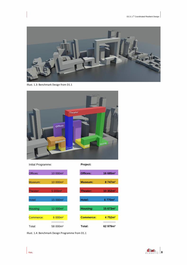
The images below show the Benchmark Design stage together with the fictitious programme within.
Illust. 1.2: Benchmark Design from D1.1
D2.3 | 1st Coordinated Resilient Design
FINAL
8
Illust. 1.3: Benchmark Design from D1.1
Illust. 1.4: Benchmark Design Programme from D1.1
Project:
Offices: 16 685m²
Museum: 8 747m²
Theater: 10 352m²
Hotel: 6 770m²
Housing: 15 673m²
Commerce: 4 752m²
-------------
Total: 62 979m²
Initial Programme:
Offices: 10 000m²
Museum: 10 000m²
Theater: 5 000m²
Hotel: 15 000m²
Housing: 12 000m²
Commerce: 6 000m²
-------------
Total: 58 000m²

D2.3 | 1st Coordinated Resilient Design
FINAL
9
2 Research methodology / results
2.1 DIVISION INTO BUILDING PARTS
As mentioned in the introduction, to make the coordination easier in terms of different members of the team
working on any different elements of the project at any one time, together with an avoidance of creating computer
files too large to handle, the decision was made to divide the building complex into several parts. Following several
discussions and meetings, it was decided to divide the Ribbon object into 5 parts corresponding generally to the
various structural elements which also generally corresponded to the different programmes around the complex.
Illust. 2.1: All 5 Ribbons
Ribbon 0: Underground Parking Ribbon 1: Large Arch
Ribbon 2: Small Arch Ribbon 3: Museum Arch Ribbon 4: Housing Arch

D2.3 | 1st Coordinated Resilient Design
FINAL
10
2.2 ARCHITECTURAL DESIGN
2.2.1 RIBBON 1: THEATRE, HOTEL & HOUSING
Illust. 2.2: Ribbon 1 including three programmes
The Large Arch incorporates three different functions, the hotel and housing on each tower, and the theatre
complex connecting the two. This allows for escape routes in both towers.
Illust. 2.3: Cut view of the housing tower
Each level of the housing tower incorporates 4 apartments, 2 one bedroomed & 2 two bedroomed.
On floors 4, 10, 17 & 24 there are 2 apartments taken up by technical rooms for the air conditioning plant.

D2.3 | 1st Coordinated Resilient Design
FINAL
11
Illust. 2.4: Cut view of the hotel tower
Similar to the housing tower but containing 8 hotel rooms.
Also as the housing tower, levels 4, 10, 17 & 24 are completely taken up by Air conditioning plant.
Illust. 2.5: Cut view of the theatre upper level
The theatre includes a seating hall with main stage & backstage. There is also entrance lobbies, a café and a
panoramic restaurant. The level below the theatre (28th
floor) has a reduced height in order to contain the structure
which is hidden from view on the underside of the "beam" together with technical plant rooms. This also allows for

D2.3 | 1st Coordinated Resilient Design
FINAL
12
a greater height in the theatre hall giving a height of 2 ½ levels (10m). On the upper and final floor of the arch beam
there are rehearsal rooms which are placed between the upper structural trusses.
2.2.2 RIBBON 2: OFFICES
Illust. 2.6: Ribbon 2 containing one programme
The Small Arch contains only one single programme, that of offices. It is located next to the railway station building.
Each tower has a structural core which contains lifts and stairwells.
Illust. 2.7: Cut view of the offices

D2.3 | 1st Coordinated Resilient Design
FINAL
13
2.2.3 RIBBON 3: MUSEUM & COMMERCIAL RETAIL
Illust. 2.8: Ribbon 3 containing two programmes
The principal function in this arch is the museum however, there is a commercial retail space on the lower 2 levels
at the rear facing the railway station entrance.
The circulation in the museum works by an entrance lobby in one tower, the visitors travel up by lift or stair to the
top and then travel down and exit by the other tower. The second tower also contains a large ventilation shaft
which comes from the underground parking.
Illust. 2.9: Cut view of the museum arch

D2.3 | 1st Coordinated Resilient Design
FINAL
14
2.2.4 RIBBON 4: HOUSING & COMMERCIAL RETAIL
Illust. 2.10: Ribbon 4 containing two programmes
The three levels which touch the street level of this ribbon are taken up by commercial retail space.
The housing levels above which create the "bridge" over the road and tramlines are mostly 1 bedroomed luxury
apartments.
Illust. 2.11: Cut view of housing bridge
2.2.5 RIBBON 0: PARKING
Illust. 2.12: Ribbon 0 containing the underground parking
There are two levels of parking for motorised vehicles with the upper level containing an area reserved for bicycle
parking. The access to the car park is from the ' BEZUIDENHOUTSEWEG' via a ramp on the north-eastern side of the

D2.3 | 1st Coordinated Resilient Design
FINAL
15
site adjacent to the New Babylon Centre. The access for the bicycles is via two escalator ramps which travel down a
void in the ground floor. There is also a void underneath the museum arch. These voids not only allow light to enter
into the underground levels but also natural ventilation, which is then extracted by the shaft in the museum tower
previously mentioned. The main void underneath the large arch is large enough to allow trees to be planted in beds
at the lower level between the bicycle parking.
Illust. 2.13: Cut view of the underground parking

D2.3 | 1st Coordinated Resilient Design
FINAL
16
2.3 STRUCTURAL DESIGN
2.3.1 STRUCTURAL INTRODUCTION: DOCUMENT GOAL AND STRUCTURE
This chapter contains the basic assumptions on the structural design (calculations) of the various buildings within
the ELASSTIC building complex. By means of currently valid European design standards, partial factors for actions,
factors, material and structural member properties, imposed loads and wind loads for buildings are dealt with
successively. Each of these subjects will be covered by separate chapters whereby the continuous preference lies
with a graphical representation of chapter content.
2.3.2 BASIC ASSUMPTIONS
2.3.2.1 STANDARDS, SPECIFICATIONS AND GUIDELINES
Standarda Description
EN1990+A1+A1/C2:2011+NA:2011 Eurocode 0: Basis of structural design
EN1991-1-1+C1:2011+NA:2011 Eurocode 1: Actions on structures – General actions – Densities, self-
weight, imposed loads for buildings
EN1991-1-2+C1:2011+NA:2011 Eurocode 1: Actions on structures – General actions – Actions on
structures exposed to fire
EN1991-1-3+C1:2011+NA:2011 Eurocode 1: Actions on structures – General actions – Snow loads
EN1991-1-4+A1+C1:2011+NA:2011 Eurocode 1: Actions on structures – General actions – Wind actions
EN1991-1-5+C1:2011+NA:2011 Eurocode 1: Actions on structures – General actions – Thermal
actions
EN1991-1-7+C1:2011+NA:2011 Eurocode 1: Actions on structures – General actions – Accidental
actions
EN1992-1-1+C2:2011+NA:2011 Eurocode 2 – Design of concrete structures – General rules and rules
for buildings
EN1992-1-2+C1:2011+NA:2011 Eurocode 2 – Design of concrete structures – Structural fire design
EN1993-1-1:2011+NA:2011 Eurocode 3 – Design of steel structures – General rules and rules for
buildings
EN1993-1-2:2011+NA:2007 Eurocode 3 – Design of steel structures – Structural fire design
EN1993-1-8+C2:2011+NA2011 Eurocode 3 – Design of steel structures – Design of joints
EN1995-1-1+A1+C1:2011+NA:2011 Eurocode 5 – Design of timber structures – General – Common rules
and rules for buildings
EN1995-1-2+C2:2011+NA:2011 Eurocode 5 – Design of timber structures – General – Structural fire
design
EN1996-1-1+C1:2011+NA2011 Eurocode 6 – Design of masonry structures – General – Common
rules and rules for buildings
EN1996-1-2+C1:2011+NA2011 Eurocode 6 – Design of masonry structures – General – Structural
fire design
EN1996-3+C1:2006+NA:2011 Eurocode 6 – Design of masonry structures – Simplified calculation
methods for unreinforced masonry structures
EN1997-1:2005+NA:2008 Eurocode 7 – Geotechnical design – General rules
CUR Recommendation 36:2000b Design of elastically supported concrete floors and hardened
surfaces
CUR Recommendation 73:2000 Stability of masonry structures

D2.3 | 1st Coordinated Resilient Design
FINAL
17
Standarda Description
a Dutch National Annexes are applicable to the ELASSTIC project
b CUR Recommendations are only available in Dutch
Table 2.1: standards and specifications
2.3.2.2 PARTIAL FACTORS FOR ACTIONS
All given values for loads and actions in design and calculation documents are characteristic. Where necessary,
these values are multiplied with partial factors (given in the table below) to obtain design values. The partial factors
are classified into 3 categories, based on the consequence classes given in the Eurocodes. In the ELASSTIC project,
the factors corresponding to consequence class 3 are applied.
Consequence
class
Design working life Partial factors for actions
Gk;j;inf Gk;j;sup Qk;i
CC1 3 (50 years) 0,90 1,22/1,08 1,35
CC2 3 (50 years) 0,90 1,35/1,20 1,50
CC3 3 (50 years) 0,90 1,49/1,32 1,65
Table 2.2: partial factors for actions
2.3.2.3
The Ψ factors can be obtained from the following table, categorised by limit states.
Areas
Characteristic Frequent
Quasi-
permanent
𝚿𝟎 𝚿𝟏 𝚿𝟐
Category A: Living areas 0,4 0,5 0,3
Category B: Office areas 0,5 0,5 0,3
Category C: Meeting/ congregation areas 0,6/0,4 0,7 0,6
Category D: Shopping areas 0,4 0,7 0,6
Category E: Storage areas 1,0 0,9 0,8
Category F: Traffic areas, vehicle weight ≤ 30kN 0,7 0,7 0,6
Category G: Traffic areas, 30kN ˂ vehicle weight ≤ 160kN 0,7 0,5 0,3
Category H: Roofs 0 0 0
Snow load 0 0,2 0
Wind action 0 0,2 0
Table 2.3: Ψ factors according to N1990+A1+A1/C2:2011: Dutch National Annex (2011)

D2.3 | 1st Coordinated Resilient Design
FINAL
18
2.3.3 MATERIAL AND STRUCTURAL MEMBER PROPERTIES
2.3.3.1 SELF-WEIGHT
Self-weight of applied materials and structural members are presented in the table below:
Material/ structural member Self-weight [kN/m³]
Concrete 24,0
Cement mortar (screeds) 20,0
Steel 78,5
Structural timber (strength class C18) 3,2
Masonry (clay bricks) 18,0
Glass 25,0
Soil and clay (wet) 20,0
Asphalt concrete 25,0
Movable partitions [kN/m²] 1,2
Hollow-core beam floors: type 260/ 320/ 400
[kN/m²]
3,8/ 4,2/ 4,8
Cast in place concrete floors (h = 280 mm) [kN/m²] 6,7
Table 2.4: self-weight of materials and structural members
2.3.3.2 MATERIAL QUALITIES AND STRENGTH CLASSES
Cast in place concrete C30/37 and C40/50
Reinforcing steel B500B
Anchor quality 8.8
Structural steel S355JRG2
2.3.3.3 PRODUCT INFORMATION
Product information sheets containing technical details regarding construction members can be found in appendix 1
to this document.

D2.3 | 1st Coordinated Resilient Design
FINAL
19
2.3.4 IMPOSED LOADS FOR BUILDINGS
Imposed loads for buildings are quantified in accordance with EN 1991, which presents characteristic values of
these loads based on functional purposes to which buildings’ areas are put. Considering the design phase and the
corresponding level of detail, only an indication of the various values can be given in this document. The table
below presents all prescribed values of imposed loads on buildings; further on in this document, imposed loads will
be linked to the various components of the ELASSTIC building complex
Category Functional purpose qk [kN/m²] Qk [kN]
Category A (Living areas and areas for domestic usage)
A Floors 1,75 3
A Stairs 2 3
A Balconies 2,5 3
A Access routes 2 3
Category B (Office areas)
B Office areas 2,5 3
B Access routes 3 3
Category C (Meeting/ congregation areas)
C1 Areas with tables 4 7
C2 Areas with fixed seats 4 7
C3 Areas without obstacles for people walking around 5 7
C4 Areas intended for physical activities 5 7
C5 Crowded areas 5 7
C Access routes 5 7
Category D (Shopping areas)
D1 Retail areas 4 7
D2 Shopping malls 4 7
D Access routes 4 4
Category E (Storage areas)
E1 Shops ≥5 ≥7
E1 Libraries ≥2,5 ≥3
E1 Access routes to libraries 3 3
E1 Other ≥5 ≥10
E2 Industrial use ≥3 ≥7
E Access routes 4 4
Category F (Traffic and parking areas for lightweight vehicles)
F Lightweight vehicles (≤25 kN)
2 10
Category G (Traffic and parking areas for medium weight vehicles)
G Medium weight vehicles (25 to 120 kN) 5 40
G Vehicles heavier than 120 kN 𝐺𝑣/𝐴𝑣 *
Category H (Roofs): see table 6: imposed loads for roofs
Category I Accessible roofs
I Functional purpose according to categories A to G inclusive
Table 2.5: imposed loads for buildings, obtained from EN1991-1-1+C1:2011: Dutch National Annex (2011)

D2.3 | 1st Coordinated Resilient Design
FINAL
20
Category Roof incline α qk [kN/m²]
Qk [kN]
H (not accessible) 0 ≥ α ≤ 15° 1 1,5b
15 ≥ α ≤ 20° 4-0,2x{α} 1,5b
α ≥ 20° 0 1,5b
Roofs of subterranean areas without traffic actions 4 7 a The uniformly distributed loads qk are to be spread out over a surface A of 10 m², within the boundaries of 0
and the total roof surface b
Acting on a surface of 0,1 x0,1m.
Table 2.6: imposed loads for roofs, obtained from EN1991-1-1+C1:2011: Dutch National Annex (2011)
Please note that self-weight of movable partitions is not included in the values presented above. However, loads
from these partitions need to be regarded as imposed loads (EN1991-1-1 art. 6.3.1.2 (8)). The following value can be
used for the aforementioned loads: for movable partitions with a self-weight >2≤3,0 kN/m wall length: qk = 1,2
kN/m².
Building Functional purpose Cat. Imposed load
qk [kN/m²]
Theater
(5.000 m²)
Areas with fixed seats C2 4
Areas intended for physical activities (stage/ access routes) C4 5
Hotel
(15.000 m²)
Areas intended for physical activities (sport/fitness centers) C4 5
Areas with tables (restaurants) C1 4
Floors in living areas and areas for domestic usage (hotel
rooms)
A 1,75
Stairs in living areas and areas for domestic usage A 2
Balconies in living areas and areas for domestic usage A 2,5
Museum
(10.000 m²)
Areas without obstacles for people walking around C3 5
Shops
(6.000 m²)
Shops/ restaurants C1/D 4
Storage areas/ areas for industrial usage/ shops E1 ≥5
Housing
(12.000 m²)
Floors in living areas and areas for domestic usage (houses) A 1,75
Stairs in living areas and areas for domestic usage A 2
Balconies in living areas and areas for domestic usage A 2,5

D2.3 | 1st Coordinated Resilient Design
FINAL
21
Building Functional purpose Cat. Imposed load
qk [kN/m²]
Offices
(10.000 m²)
Office areas B 2,5
Areas without obstacles for people walking around
(conference halls)
C3 5
Parking areas (9.000
m²)
Traffic and parking areas for lightweight vehicles –
Lightweight vehicles (≤25 kN)
F 2
General Storage areas/ areas for industrial usage/ other E2 ≥3
Roofs solely accessible for maintenance purposes H 1
Roofs of subterranean areas without traffic actionsa H 4
a Roofs of subterranean parking garages are covered with 0,5 meters of soil
Table 2.7: imposed loads for buildings, allocated to ELASSTIC building complex components
2.3.5 WIND ACTIONS
Quantification of wind loads on ELASSTIC buildings will be based on the requirements provided by the appropriate
Eurocode (EN1991-1-4). This chapter solely covers the determination of global effects of wind actions; local effects
will be left out of account in this document. Furthermore, no extensive attention is paid to specific, local conditions
for the ELASSTIC project location. The determination of wind actions using this document will therefore result in an
approximation of actual actions; wind tunnel research needs to be carried out in order to obtain more accurate
results.
2.3.5.1 LAY-OUT AND ORIENTATION OF ELASSTIC BUILDINGS
Based on shape, size and structural coherence, the ELASSTIC project has been divided in four buildings, which are
subdivided into building units where necessary. This (sub)division is pointed out using the images below.
Illust. 2.16: lay-out and orientation of ELASSTIC buildings
1. Theatre building: theatre (red), hotel (blue) and the housing tower (green);
2. Housing building: housing areas excluding housing tower (green), supplemented by the shopping areas between
housing and office areas (olive).
3. Office building: all office areas (lavender);
4. Museum buildings: museum areas (orange), completed by shopping areas excluding those belonging to the
housing building.
Regarding wind actions, two scenarios will be taken into account, being south wind and east wind (see the image
above).

D2.3 | 1st Coordinated Resilient Design
FINAL
22
2.3.5.2 CALCULATION METHOD
Wind actions on ELASSTIC buildings are considered as wind forces and will be determined using force coefficients.
Paragraph 5.3.2 of EN1991-1-4 will be used for this determination (art. 5.3 (2)).
𝐹𝑤 = 𝑐𝑠𝑐𝑑 × ∑ 𝑐𝑓
𝑒𝑙𝑒𝑚𝑒𝑛𝑡𝑠
× 𝑞𝑝(𝑧𝑒) × 𝐴𝑟𝑒𝑓
Where:
cscd structural factor
cf force coefficient
qp(ze) peak velocity pressure at reference height ze
Aref reference area of the structure or structural element
2.3.5.2.1. STRUCTURAL FACTOR CSCD
Given the complexity of the available determination methods and the relatively small impact of this factor on total
wind actions, this factor will be taken as 1. This simplification of calculations is justified by the required level of
detail during the current design stage and the fact that wind tunnel research should be done in the future to
determine more exact values of the wind actions.
Furthermore, an approximation of the structural factor has been made using the Dutch national standards which
are cancelled with the introduction of the Eurocodes. This approximation, which can be found in appendix 2 to this
document, shows that the above-mentioned assumption provides sufficient accuracy for the calculations during this
design phase (CSCD = 1,015).
2.3.5.2.2. FORCE COEFFICIENT AND REFERENCE AREA
Both the force coefficient and the reference area are specific to individual ELASSTIC buildings and depend among
others on the size and shape of the considered structure. These factors will be treated further on in this chapter.
2.3.5.2.3. PEAK VELOCITY PRESSURE
Values for the peak velocity pressure are provided by the national annex to EN1991-1-4 and are dependent of
reference height ze and location-specific factors such as wind area and built-on/unbuilt-on environment. The
ELASSTIC project is situated in The Hague, Netherlands (wind area II) in a built-on environment (conservative
assumption). For each ELASSTIC building, peak velocity pressures have been determined: these pressures are shown
in the images below.

D2.3 | 1st Coordinated Resilient Design
FINAL
23
2.3.5.2.4. PEAK VELOCITY PRESSURE THEATER BUILDING
Illust. 2.17: peak velocity pressure theatre building: east wind
Illust. 2.18: peak velocity pressure theatre building: south wind

D2.3 | 1st Coordinated Resilient Design
FINAL
24
2.3.5.2.5. PEAK VELOCITY PRESSURE OFFICE BUILDING
Illust. 2.19: peak velocity pressure office building: east wind
Illust. 2.20: peak velocity pressure office building: south wind
2.3.5.2.6. PEAK VELOCITY PRESSURE HOUSING BUILDING
Illust. 2.21: peak velocity pressure housing building: east wind

D2.3 | 1st Coordinated Resilient Design
FINAL
25
Illust. 2.22: peak velocity pressure housing building: south wind (1)
Illust. 2.23: peak velocity pressure housing building: south wind (2)
2.3.5.2.7. PEAK VELOCITY PRESSURE MUSEUM BUILDING
Illust. 2.24: peak velocity pressure museum building: east wind
D2.3 | 1st Coordinated Resilient Design
FINAL
26
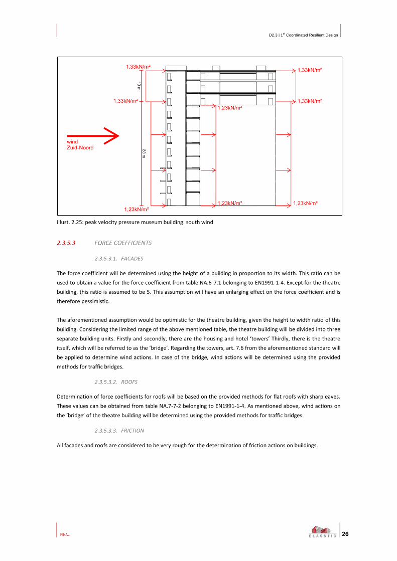
Illust. 2.25: peak velocity pressure museum building: south wind
2.3.5.3 FORCE COEFFICIENTS
2.3.5.3.1. FACADES
The force coefficient will be determined using the height of a building in proportion to its width. This ratio can be
used to obtain a value for the force coefficient from table NA.6-7.1 belonging to EN1991-1-4. Except for the theatre
building, this ratio is assumed to be 5. This assumption will have an enlarging effect on the force coefficient and is
therefore pessimistic.
The aforementioned assumption would be optimistic for the theatre building, given the height to width ratio of this
building. Considering the limited range of the above mentioned table, the theatre building will be divided into three
separate building units. Firstly and secondly, there are the housing and hotel ‘towers’ Thirdly, there is the theatre
itself, which will be referred to as the ‘bridge’. Regarding the towers, art. 7.6 from the aforementioned standard will
be applied to determine wind actions. In case of the bridge, wind actions will be determined using the provided
methods for traffic bridges.
2.3.5.3.2. ROOFS
Determination of force coefficients for roofs will be based on the provided methods for flat roofs with sharp eaves.
These values can be obtained from table NA.7-7-2 belonging to EN1991-1-4. As mentioned above, wind actions on
the ‘bridge’ of the theatre building will be determined using the provided methods for traffic bridges.
2.3.5.3.3. FRICTION
All facades and roofs are considered to be very rough for the determination of friction actions on buildings.

D2.3 | 1st Coordinated Resilient Design
FINAL
27
2.3.6 STRUCTURAL DESIGN
This chapter describes the structural design. This structural design is based on the assumptions described above
paragraphs and on the architectural design. The result of the design and calculation is shown in the BIM models.
Overall, the various ribbons starts with a pile foundation with a concrete vertical building part and horizontal
building part constructed with a steel structure at the top of the ribbons.
In the following paragraphs, we explain the structural design further in detail
Illust. 2.26: structure of the Ribbon
2.3.6.1 FOUNDATION
In the centre of The Hague the load bearing layers are at a depth of 20m
below ground level. This layer forms the base of the foundation of the
ribbons. From top the soil layers consist mainly of sands. At a depth of 13m
a layer of clay is present of approximately 3m thick. After this layer begins
the fixed packed layers of sand which are suitable for the foundation.
To reach this layer we use piles with a diameter of 508mm and a footing of
556mm. The piles have a capacity of approximately 2500KN. Under the
towers of the ribbons the foundation consists beside the piles out of a
foundation slab with a thickness of 3m that captures both the horizontal and
vertical forces.
Foundation slab
Foundation piles
Illust. 2.27: foundation tower Ribbon1

D2.3 | 1st Coordinated Resilient Design
FINAL
28
Under a large part of the buildings, there is a
parking. This garage is located below the
groundwater level. The water level is about
1,5m beneath the ground level.
Where the parking located under the standing
towers, the piles are under pressure. While
the parts where there is not a building above
the piles are charged with tensile loads by the
upward water pressure. The capacity of the
piles for tension is about 600kN.
Temporary sheet piles will be used for the
construction phase of the parking. For the
temporary seal of the building pit underwater
concrete is used which is been held in place
by the piles. In that phase al the piles need
their tension capacity.
Illust. 2.29: pile plan parking with pressure areas from buildings
Foundation level
Illust. 2.28: typical CPT The Hague

D2.3 | 1st Coordinated Resilient Design
FINAL
29
2.3.6.2 PARKING
The structure of the parking exists of a concrete box. The vertical bearing elements of the towers puncture through
the parking and find their way down to the foundation. Beside these areas the box is filled up with prefabricated
columns, beams and slabs based on a grid 8x16m. On the deck is taken into account a layer of 0,70m of soil for
foundation of roads and for growing of plants.
2.3.6.3 RIBBON 1
Ribbon 1 is the largest arch of all the ribbons. This building part
has two towers with a beam with a span of 112m. The roof is
on a level of 128m.
The two towers are casted in place by a tunnel formwork
which is used a lot in the Netherlands for construction of
condominiums. One tower is a hotel, the other is residential
both can be constructed in the same way.
On the lower levels there is used a higher concrete grade the
higher levels because of the pressure in the walls so that the
same size can be used for the walls. On the corners of the
walls there are large columns placed which bears the big horizontal beam of the ribbon. So the walls and floors are
cast in place for the towers. All the walls have a function in the stability of the building.
On the 28th
level the structure changed. On that level the double trusses are fixed on the concrete columns. The
three level high double trusses have to span the 112m. On both side of the theatre at the top levels there are
double trusses used. Between this trusses secondary trusses are placed which are bearing the hollow section
concrete floors.
2.3.6.4 RIBBON 2, 3 AND 4
The structural principal of ribbon 2, 3 and 4 is the same as ribbon 1. The trusses on the beam level aren’t double but
single and the floors make in one span from truss to truss without the secondary trusses because the span is less.
The rest is pretty more the same.
Special for Ribbon 3 and 4 is that the beam on top of the little towers makes a shift of 90 degrees. To reach this we
make in one tower a steel cantilever to support the beam.
Illust. 2.31: Structure Ribbon 3 with cantilever and beam and example project
Illust. 2.30: tunnel formwork

D2.3 | 1st Coordinated Resilient Design
FINAL
30
The floors of the upper levels which are supported by the steel structure are hollow section floors. The different
used types are shown in the appendix.
Illust. 2.32: prefabricated hollow section floor
2.4 SERVICES DESIGN
2.4.1 SERVICES INTRODUCTION
2.4.1.1 GOAL OF MEP DESIGN
In the stage of preliminary design the main tasks for the MEP discipline is to provide the design team with
information on the size and location of the technical spaces, shafts and main infrastructure because these aspects
have an influence on the shape of the architecture and on the design of the structures. The exact location of size of
the technical spaces and shafts are determined in an iterative design process with architect and structural
engineers. Information on size and location are communicated using the BIM model. This chapter gives a brief
inside in the scope of the MEP Design presented and the used assumptions.
In order to be able to determine the size and location of the technical spaces, the main infrastructure and the shafts
the basic installation concepts have been determined only to be able to size certain components. Based on these
concepts the capacity of the main air handling units, ducts, heating and cooling devices like heat pumps, boilers,
pipes, sanitary equipment and electrical central equipment have been determined.
2.4.1.2 LEVEL OF DETAIL
In a typical preliminary design phase not all design parameters for the MEP-installation like room arrangement,
occupation, size of windows or physical properties of walls and windows are fixed yet. Also within this project there
is not a specific brief with requirements for the different functions within the building. Since the input parameters
are still flexible, the level of detail of MEP installations is accordingly coarse. The level of detail is based on the
necessary usage within this project. Relevant for the project is information on location of important and critical
services in the building which can be affected during one of the hazard scenarios. Therefore the BIM model shows
relevant space reservations for the main components and main infrastructure.

D2.3 | 1st Coordinated Resilient Design
FINAL
31
2.4.2 DIMENSIONING
2.4.2.1 ASSUMPTIONS
Since there is no specific client brief available some assumptions have been made based on common
knowledge/sense and local codes. Loads for heating, cooling, electric peak demand are based on square meter
indicators for the different functions within the building. Also the exact properties of the building envelope are not
yet determined very specifically in this preliminary design. The chosen indicators do reflect the intention of the
quality of the building envelope to consider when the design is further developed.
Appendix 1.4 includes the room list of this building. The list shows the rooms in the building and the main
assumption made with respect of ventilation rates, heating and cooling loads.
2.4.2.2 MAIN FUNCTIONS
For the main functions in the Ribbon complex the most important results for heating, cooling and air handling are
summarized below.
Office Hotel Private
Residential
space
Theater Museum
External cooling load (W/m²) 30 20 20 50 10
Internal cooling load (W/m²) 30 11 5 105 25
External heat load (W/m²) 50 50 50 50 50
Ventilation rate (m³/h/m²) 3,6 3 76 (per unit) 37 9
Table 2.8: Heating, cooling and air handling summarised results
Climate concepts
Office: local heating and cooling using climate control ceilings
Hotel Room: local heating and cooling using fan-coil units
Private residential space: local floor heating and cooling
Theater: cooling using central ventilation air, local radiation devices for heating
Museum: all-air heating and cooling.
2.4.2.3 MAIN DIMENSIONS
Based on the assumption of the main functions the dimensions of critical size determining installations are
determined. These are for instance:
- size of main air handling units and number of air handling units;
- size of heating equipment like heat pumps, chillers and boilers;
- size of transformer rooms;
- size of main equipment rooms for electrical distribution, like panels.
The different functionalities in the Ribbon requires a specific type of installation and space usage. The size of the
plant spaces and the required space for the main infrastructure is an input parameter for the integrated design. The
location of the plant spaces and routing of main infrastructure has been determined in an iterative design with the
architect and structural engineer. The calculations were performed on a coarse level, the accuracy of the
dimensions of the technical spaces and shafts can therefore not be 100%. One must assume some reservations in
the dimensions.

D2.3 | 1st Coordinated Resilient Design
FINAL
32
2.4.3 MAIN INFRASTRUCTURE AND PLANT SPACE
With the information as mentioned in paragraph 2.4.2 the necessary main infrastructure and plant spaces have
been modelled in BIM. However before this was done the main infrastructure for different installations have been
presented in 2D schematics. This is necessary to understand the different needs and locations for shafts. Based on
these schematics the cores/shaft have been looked at in more detail to determine the influence on the architectural
plans. This influence has been discussed and resulted in changes in the architectural layout and structural
coordination.
Illust. 2.26: Examples of ventilations schemes
After the first coordination the schematics have been translated into the BIM model. The plant spaces and shafts
are modelled as solid masses.
In the basics the parking garage will host the central heating and cooling plant as well as the transformers and main
electricity connections to the grid. Air distribution typically requires large area’s to minimize these ducts, the air
handling units are distributed through the building. Air handling units are located depending on the different
functions and their location in the Ribbon. This will also hold for heating, cooling, tap water and electricity sub
distribution systems. All these spaces are connected by vertical (shafts) and horizontal routes.
An example from the BIM model is shown in the figure below.

D2.3 | 1st Coordinated Resilient Design
FINAL
33
Illust. 2.27: MEP spaces in the Ribbon

D2.3 | 1st Coordinated Resilient Design
FINAL
34
3 Discussion and conclusion
The objective of tasks T2.2, T2.3 and T2.4 was to take the previously designed benchmark design and together with
the architectural & engineering teams, create a concept design which was both coordinated and quantifiable in
terms of structural stability and technical service integration. The outcome was to be in the form of a BIM model (or
several) in order that it could be used by the various researchers studying the different hazard scenarios in Work
Packages n°2 & n°3.
This BIM model was achieved and the various elements placed on the BIMserver in the IFC format for all to access.

D2.3 | 1st Coordinated Resilient Design
FINAL
35
4 Acknowledgment
“This project has received funding from the European Union’s Seventh Framework Programme for research, technological development and demonstration under grant agreement no 312632”.
http://cordis.europa.eu/fp7/cooperation/home_en.html
http://ec.europa.eu
PROJECT PARTICIPANTS:
TNO – NEDERLANDSE ORGANISATIE VOOR TOEGEPAST NATUURWETENSCHAPPELIJK ONDERZOEK (NL)
ARCADIS NEDERLAND BV (NL)
FRAUNHOFER-INSTITUT EMI (DE)
INSTITUTO CONSULTIVO PARA EL DESARROLLO SL (ES)
JA JOUBERT ARCHITECTURE (NL)
NORTH BY NORTH WEST ARCHITECTES SARL (FR)
SCHÜΒLER-PLAN INGENIEURGESELLSCHAFT MBH (DE)
SIEMENS AG (DE)
UNIRESEARCH BV (NL)
Disclaimer
The FP7 project has been made possible by a financial contribution by the European Commission under Framework
Programme 7. The Publication as provided reflects only the author’s view.
Every effort has been made to ensure complete and accurate information concerning this document. However, the
author(s) and members of the consortium cannot be held legally responsible for any mistake in printing or faulty
instructions. The authors and consortium members retrieve the right not to be responsible for the topicality,
correctness, completeness or quality of the information provided. Liability claims regarding damage caused by the
use of any information provided, including any kind of information that is incomplete or incorrect, will therefore be
rejected. The information contained on this website is based on author’s experience and on information received from
the project partners.

D2.3 | 1st Coordinated Resilient Design
FINAL
36
Appendix 1 Appendix List
APPENDIX 1.1 Technical details – construction members
Hollow-core slab floors . . . . . . . . 37
APPENDIX 1.2 Approximation of structural factor cscd . . . . 41
APPENDIX 1.3 Structural Report . . . . . . . 42
APPENDIX 1.4 ELASSTIC complex room list . . . . . . 61

D2.3 | 1st Coordinated Resilient Design
FINAL
37
Appendix 1.1 Technical details –
construction members
This appendix contains technical details of construction members used in the ELASSTIC project. These details are
provided by the corresponding fabricants, mostly through their websites. The following documents are included in
this appendix:
1) Hollow-core slab floors (types 260, 320
and 400); VBI

asdf
: ARCADIS
3
Technical specifications Hollow core slab 260
Weight including joint filling 376 kg/m2
Environmental class XC1, XC3 (applicable to floors which are exposed to the
open air)
Fire resistance Maximum 120 minutes
Maximum slab length:
- Dwellings
- Buildings with other functions
10,0 m
12,6 m
Slab width 1,2 m
Width of the fitting slab 300 + n x 150 mm
Joint filling 11,1 liter/m1
Strength class C45/55
Concrete section 177829 mm2
Centre point of section 122,9 mm
Area moment of inertia (I) 1434,9 x 106 mm
4
Finish Normal or coarse
Section Hollow core slab 260
Structural properties Hollow core slab 260

asdf
4
ARCADIS :
Technical specifications Hollow core slab 320
Weight including joint filling 415 kg/m2
Environmental class XC1, XC3 (applicable to floors which are exposed to the
open air)
Fire resistance Maximum 120 minutes
Maximum slab length 14,7 m
Slab width 1,2 m
Width of the fitting slab 400 + n x 200 mm
Joint filling 12,9 liter/m1
Strength class C45/55
Concrete section 195605 mm2
Centre point of section 151,3 mm
Area moment of inertia (I) 2362 x 106 mm
4
Finish Normal or coarse
Section Hollow core slab 320
Structural properties Hollow core slab 320

asdf
: ARCADIS
5
Technical specifications Hollow core slab 400
Weight including joint filling 475 kg/m2
Environmental class XC1, XC3 (applicable to floors which are exposed to the
open air)
Fire resistance Maximum 120 minutes
Maximum slab length 18 m
Slab width 1,2 m
Width of the fitting slab 400 + n x 200 mm
Joint filling 15,7 liter/m1
Strength class C45/55
Concrete section 222974 mm2
Centre point of section 189,5 mm
Area moment of inertia (I) 4264 x 106 mm
4
Finish Normal or coarse
Section Hollow core slab 400
Structural properties Hollow core slab 400

D2.3 | 1st Coordinated Resilient Design
FINAL
41
Appendix 1.2 Approximation of structural
factor cscd
Enlargement factor φ1 for wind actions (in accordance with NEN 6702)
ℎ = 128𝑚 (building height)
𝑏 = 16𝑚 (building width)
𝐷 = 0,02 (dampening for concrete)
𝑎 = 0,25𝑚
𝑠2 (vibration acceleration)
𝛿 = 0,256 𝑚 (horizontal deformation of the structure)
𝑓𝑒
= √𝑎
𝛿= √
0,25
0,256= 0,99 𝐻𝑧
𝐼(ℎ) =1
ln (ℎ
0,2)
=1
ln (1280,2
)= 0,155
𝐵 =1
0,94 + 0,021ℎ23 + 0,029𝑏
23
=1
0,94 + 0,021 ∗ 12823 + 0,029 ∗ 16
23
= 0,6
𝐸 =0,0394 ∗ 𝑓𝑒
−23
𝐷 ∗ (1 + 0,1 ∗ 𝑓𝑒 ∗ ℎ) ∗ (1 + 0,16 ∗ 𝑓𝑒 ∗ 𝑏𝑚)=
0,0394 ∗ 0,99−23
𝐷 ∗ (1 + 0,1 ∗ 0,99 ∗ 128) ∗ (1 + 0,16 ∗ 0,99 ∗ 16)= 0,04
𝜙1 =1 + 7 ∗ 𝐼(ℎ) ∗ √(𝐵 + 𝐸)
1 + 7 ∗ 𝐼(ℎ) ∗ √𝐵=
1 + 7 ∗ 0,155 ∗ √(0,6 + 0,04)
1 + 7 ∗ 0,155 ∗ √0,6= 1,015
The enlargement factor is φ1 = 1,015.
For the calculation of the wind actions this factor will be taken as 1, this simplification is justified by the required
level of detail during the current design stage.
For a subsequent stage this enlargement factor needs to be determined more exactly using wind tunnel research.
D2.3 | 1st Coordinated Resilient Design
FINAL
42
Appendix 1.3 Report on using the BIM model
as input for the structural calculations
In order to improve the efficiency of making structural calculations, ARCADIS also researched the possibilities of
using the BIM model as input for the structural calculations. This is done with regard to the use of the BIM model
further in the project, where an iterative process between the calculations and updates on the BIM model will play
an important role of the design against hazard scenarios. The findings on this topic are elaborated in this annex:

MEMO
ARCADIS NEDERLAND BV
Lichtenauerlaan 100
P.O. Box 4205
3006 AE Rotterdam
The Netherlands
Tel +31 10 2532 222
Fax +31 10 2532 194
www.arcadis.nl
BUILDINGS DIVISION
Page
1/18
Subject:
Elasstic, the link between the BIM models in Revit
and in Scia Engineer
Rotterdam,
10 October 2014
From:
ir. P.C. Kuiper
Drafted by:
ir. P.C. Kuiper
Department:
Divisie Gebouwen Rotterdam
Our ref.:
:
To:
T. Borst
S. Surya
Copies:
Goals of the research For the project Elasstic a 3D BIM model is available in the context of Revit. The goal of this research is
to make an export to the finite element modelling (FEM) calculation program Scia Engineer.
There are two sub goals:
1.To find a correct way of exporting the BIM model from Revit to Scia Engineer.
2.To give an idea of the future possibilities to use IFC for calculations
Steps of the investigation 1. To export a test model from Revit to IFC and further on to Scia Engineer.
2. To make a direct export from Revit to Scia by means of the add-in SE Revit Link.
3. Analyse the results of the export of both models.
4. Make an export of the complete Elasstic model from Revit to Scia.
5. By informed by an employee of the Software Development Department of Scia Engineer about
the future plans.
Preface on IFC Characteristics of IFC What is IFC? Wikipedia gives the following information:
Source: http://en.wikipedia.org/wiki/Industry_Foundation_Classes

Page 2/18
The Industry Foundation Classes (IFC) data model is intended to describe building and construction
industry data.
It is a platform neutral, open file format specification that is not controlled by a single vendor or group of
vendors. It is an object-based file format with a data model developed by buildingSMART (formerly the
International Alliance for Interoperability, IAI) to facilitate interoperability in the architecture, engineering
and construction (AEC) industry, and is a commonly used collaboration format in Building information
modeling (BIM) based projects. The IFC model specification is open and available.[1] It is registered by ISO
and is an official International Standard ISO 16739:2013.

Page 3/18
An flow chart of the different characteristics that IFC can contain, is depicted below. This is an
international agreement of the different parties in the building process and recorded by the
organisation Building Smart.
Source: http://www.buildingsmart-tech.org/ifc/IFC2x3/TC1/html/index.htm
Figure 1 Flow chart of the different domains and characteristics within IFC
The most important data for the export to calculation software belong to the Structural Analysis
Domain. Another important domain is the ‘Structural Elements Domain’. Both of them are discussed
below.
Structural Elements Domain (architectural) This domain contains elements like walls, columns, beams, openings in walls etc. These have only
geometrical properties like:
- Coordinates of the geometrical objects
- Cross-section
- Name of the element. If the name is clearly defined, the material type can be seen, but in Scia it is
not a different property.
Coördination view

Page 4/18
This domain does not do anything with analytical lines one can define in Revit.
Structural Analysis Domain (structural) This domain is meant for making exporting the necessary data for analytical calculations. An export
contains e.g.:
- Coordinates of the analytical lines
- Cross-section
- Material
- Excentricity of the analytical lines in comparison to the geometrical object
The analytical lines in the Revit BIM model are very important for being able to make a calculation.
They represent the hart lines were the forces work. Import is that the analytical line of adjoining walls
and floors are conncected in one point. Software like Scia Engineer ‘knows’ then that one object can
transfer forces to another object. In figure 2 the analytical lines are shown in blue.
How does Revit handle IFC? For an export to IFC Revit uses the so-called Coordination view. This contains the 4 domains that are
shown in figure 1. The architectural domain is being exported, but the structural domain is not.
There is no known software available that can make an export to the structural domain of IFC.
Therefore Nemetschek Scia has not yet build in the possibility to import this structural domain.
Export via Revit - to ifc 2x3 - to Scia
Geometrical model and analytical lines As a first test we took a fragment of the total Elasstic model, namely two stories of one tower. This
model contains two floors and several walls and columns. See picture below.
Figure 2 Test model in Revit (saved as ‘R+2_Constr_Res’)
The analytical lines (in dark blue for columns and light blue for walls) are well connected.

Page 5/18
Export to IFC Via de Export table we tried to write some data to the category ‘Analytical Columns’ by referring to the
class ‘IfcColumn’. Same way for floors and walls.
Figure 3 Export table in Revit
Result, seen from Scia Engineer On the picture below the result of the IFC file in Scia is shown. The columns are not connected well
(see the red circle), while in Revit the analytical lines were yet good connected.
Figure 4Imported IFC model in Scia (saved as ‘test2’)

Page 6/18
Two column were connected ‘by coincidence’, because they are not direct in line with the wall.
Figure 5 Imported IFC model in Scia with accidentally good connected columns
Conclusion Writing down the data from Revit to the Analytical Domain did not succeed. By importing in Scia it
appeared that most columns were not good connected. The information does not arrive in IFC.
Because of this, the analytical lines were incorrect, and correcting al the errors in Scia costs a lot of
time.
Using IFC as a link between Revit and Scia is not a success.
Direct export from Revit to Scia by means of an add-in About the add-in Nemetschek Scia has made an add-in, namely ‘SE Revit Link’. This can make a direct export of
analytical data to Scia.
Arcadis has two licences for this add-in, this one is called Revit Structure Interface (ESA.21).
This add-in is suitable for different versions of Revit.

Page 7/18
Test model The result of the direct export is shown below.
Figure 6 Model in Scia, result of direct export from Revit (‘R+2_Constr_Res.esa’)
Figure 7 Enlarged detail of the columns
The walls are all well connected. Nevertheless the columns are not connected to the walls, because they
have an offset. So it is the task of the structural engineer to deal with this well.
In the end, the load are being transferred from the wall to the floor and then to the columns, so this
model should work fine.
Even the load cases are exported.

Page 8/18
Figure 8 Load cases in Scia, geïmporteerd vanuit Revit
Conclusion The export went well; all columns are connected.
The terms for doing this are the analytical lines in Revit are being well defined.
Complete Elasstic model met directe export Views in Revit This is the model in Revit:
Figure 9 Views in Revit

Page 9/18
Figure 10 Views in Revit
Figure 11 Views in Revit

Page 10/18
Result in Scia In this paragraph the result in Scia are to be treated, and the solutions for the errors we experienced.
When exporting the first time, we got the following error: the add-in could not translate the column
type that was used. This type had a height and a width.
Figure 12 Error when exporting: the columns are not recognized.
We solved it by changing the type of column in Revit to a square column. Then the export was
possible.
IFC export report:
Exported entities:
462 bars
448 columns
533 beams
1090 slabs
Errors and messages :
No errors or messages are reported.
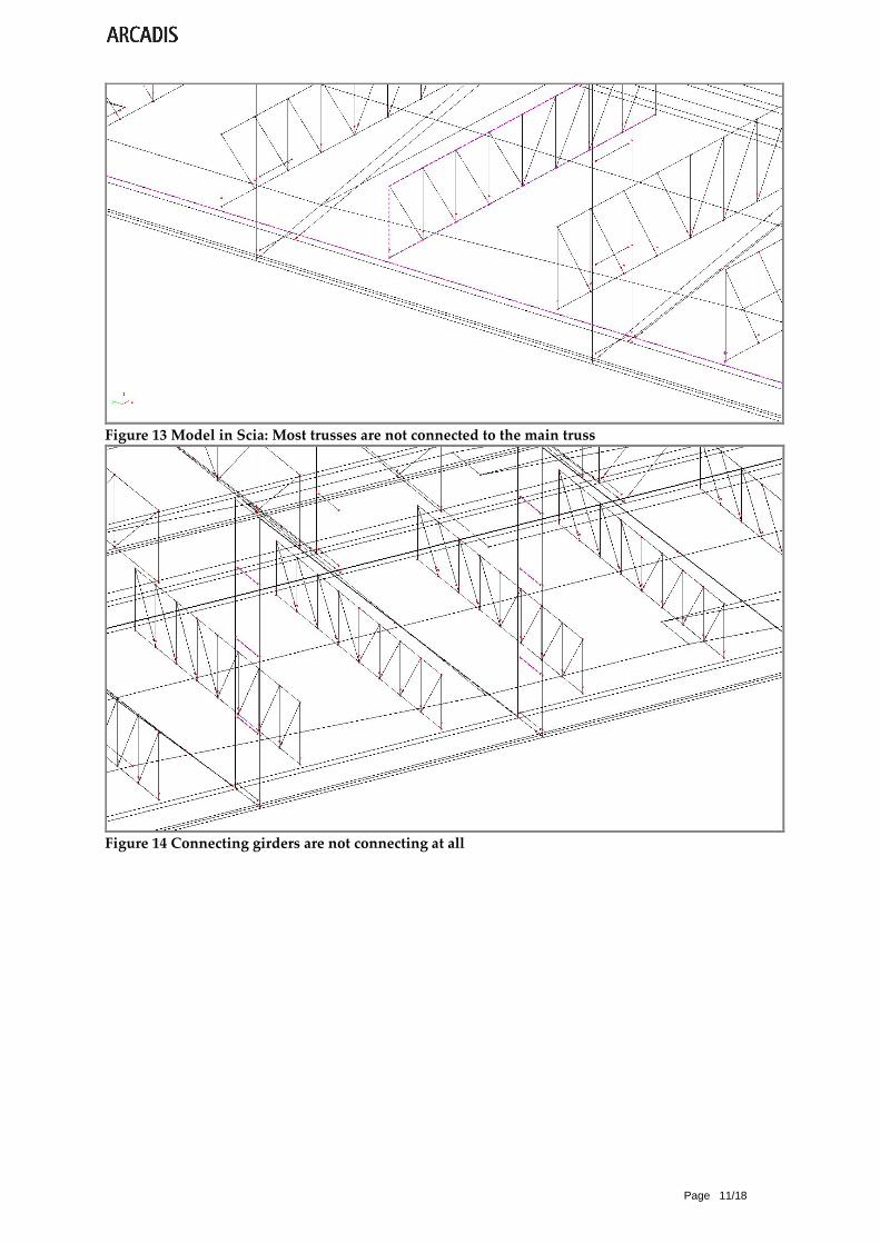
Page 11/18
Figure 13 Model in Scia: Most trusses are not connected to the main truss
Figure 14 Connecting girders are not connecting at all

Page 12/18
Figure 15 This girder suddenly finishes
Figure 16 This slab lacks (the shaded slab is added)

Page 13/18
Figure 17 The main girders does not connect
Figure 18 Solution: change the coordinates so the beams are connected, and add dummy beams

Page 14/18
Figure 19 Same view in 3D
Summary of the process The export went fast. You need to click to confirm some screens and then the model is exported in a
few minutes.
It can be seen that the analytical lines in Revit are not connecting in one point. That is logical, because
the structure is a special building and not a frame of lines. So buddy members were needed to let all
the members work together. This post processing quite much time: around 10 hours.
The result is a model in Scia Engineer which could be calculated. A simple calculation with the self-
weight of the building was performed. That worked.
Then a IFC export model was made, which can be used in the future for calculations with another
program then Scia Engineer.

Page 15/18
Direct exports combined with import ifc model introduction A useful addition is the following: you can both import the analytical and geometric model from Revit.
For the analytical model, use the SE Revit Link. After that, you will also export the model as IFC.
Working in Scia open the analytic model, and import your extra geometric model.
The two models are then superimposed.
The advantage is that you can adjust the analytical model, and customize eccentricities while the
original shape of the reference model is being seen. Now you can customize the structural model for
such tricky things like a console, in order to make a safe calculation. The geometric model remains
visible as a reference, so you wil see if the scheduling is a true reflection of reality.
Actually, you can make one of the models invisible by turning off one layer in Scia.
Figure 20 View in Scia van het model ‘R+2_Constr_Res_refmodel.esa’

Page 16/18
Analysis of the geometrical model The gray model below is the result of the IFC import model and concerns the architectural view.
This shaded column has a “geometric status” and is drawn in a different layer as the structural model,
namely' S-COLS -___- OTLN’. The element is called '300_28_ISR_column_square_concrete: 1000x1000mm:
2285'. Because of the naming (in the way that is common within Arcadis), the material can be
recognized. The material is not defined separately in Scia, since it is an architectural view.
Figure 21 View in Scia with the geometrical model shaded
Analysis of the analytical model The green model is the direct export and means the structural analysis model.
The shaded object has the type ‘column’ and material ‘concrete C30/37’ and is drawn in ‘Layer1’. This
layer can be calculated as a FEM model.
Figure 22 View in Scia with the shaded analytical model

Page 17/18
Future of IFC Ideas within Nemetschek Scia On October 6, 2014 we spoke with Dennis Mensen, an employee from the development of Scia.
Consequently the following issues emerged:
- There is not a single software program what data to the IFC Structural Analysis Domain can send.
- Scia therefore not yet support the import of the Structural Domain of IFC.
- Once software who can write to this field comes on the market Scia will also bring in the
development
- Until that time the add-in works well.
- Scia see the benefits of IFC in because it is a European standard, and they could therefore
communicate with multiple programs.
The following vision emerged from the discussion:
Future direction of transfer of information between architectural and structural model The expectation is that data traffic is a one-way direction in most projects, where information from
Revit to other software programs such as Scia is sent. This Revit model is managed by the modeller,
and the engineer uses the derived information for the calculations. If the engineer wants to make
changes, he gives the modeller instructions by using a sketch, a drawing with dimensions from Scia or
just verbally. The modeller incorporated it into the main model.
However, one can imagine a project where complex forms need to be optimized. For example, a project
with many different cross-sections. In such a project is is logical to send the data from Scia directly to
Revit. Now the engineer has a more leading role in the design.
Structural information should be entered in Revit As an engineer just want to calculate the state of affairs of the head model at several stages of the
design process, the export information from Revit should already as complete as possible. In other
words, the analytical lines must be entered correctly into the Revit model. Otherwise a repair
operations should be executed each time the model is exported, in order to let all the elements be well
connected. That takes a lot of time, and gives each time errors.
Entering the analytical lines happens partly automatically within Revit. Here you can manually specify
preferences which elements have priority when connecting. Experience will learn if this goes smoothly,
but with some training a modeller can enter most of the analytical lines. The engineer can check in
Revit or Scia if it is done well. Adaptations he can do in the Revit model.

Page 18/18
Conclusion The purpose was as follows:
1. To find a correct way of exporting the BIM model from Revit to Scia Engineer.
2. To give an idea of the future possibilities to use IFC for calculations
The results are as follows:
1. Tests are executed with a test model and the complete model of Elasstic. Export is done in two
ways:
a) Export from Revit to IFC 2x3 to Scia.
It turned out that the export from Revit to IFC does contain architectural but no accurate
structural information. Proved many structural elements when importing into the calculation
program Scia Engineer, were not properly connected to each other. So calculations could not
yet be elaborated with the model, so a repair action was needed first. This is very laborious.
b) Direct export from Revit to Scia through an add-in.
The export went fast, and the elements were connected better then with option a. Yet it took
quite some time to repair the structural model.
2. The test was done with a model that was not build with the idea of exporting it. So the analytical
lines were not intentionally entered into the model. Only quick a few adjustments were made.
However, the lines looked quite good in Revit. Yet the export file needed quite a lot of work in
order to make it ‘calculatable’.
As an engineer my point of view is that the easiest way is importing the Revit model as a
geometrical model in Scia, and use it as a reference; then you draw the structural model by hand.
The advantage is that one had the control of all the connections in the structural model, because
one minor detail can make the whole model corrupt.
My expectation is that for a simple model a direct structural export can be possible. But only when
both modellers and engineers know how to work well with Revit.

D2.3 | 1st Coordinated Resilient Design
FINAL
61
Appendix 1.4 ELASSTIC complex room list
Recommended

![MULTIDRONE MULTIple DRONE platform for media production · deliverables [D2.2]/[D2.3] which are themselves based on the requirements from the media partners. These requirements are](https://img.pdfslide.us/doc/110x75/5f0ac02d7e708231d42d28ff/multidrone-multiple-drone-platform-for-media-production-deliverables-d22d23.jpg)
![Long-term Performance of Engineered Barrier Systems PEBS · [PEBS] (D2.3-1) – Feasibility report on GAME mock-ups & (D2.3-2) – Reports on GAME status (18 months) Dissemination](https://img.pdfslide.us/doc/110x75/5f96f7159bb7f7362d1060d2/long-term-performance-of-engineered-barrier-systems-pebs-pebs-d23-1-a-feasibility.jpg)