CHAPTER 4
DEFINITION OF THE SYSTEM MODEL
Manfred Broy1 and Marıa Victoria Cengarle1 and
Hans Gronniger2 and Bernhard Rumpe2
1Software and Systems Engineering, Technische Universitat Munchen, Germany2Software Systems Engineering, Technische Universitat Braunschweig, Germany
4.1 INTRODUCTION
This chapter is devoted to the definition of a system model tailored towards UML.
The hierarchy of theories that compose the system model is stepwise introduced.
These theories are combined into a theory of sophisticated state transition systems.
The semantics of a word in a UML sublanguage, i.e., a diagram, can then be defined
by a set of such transition systems. Given two or more actual diagrams, possibly
forming a complete UML model, the semantics of them together is defined by the
intersection of their translations into the system model. In other words, consistency
of a model is defined by non-empty intersection of the sets containing the transition
systems that implement the diagrams individually.
UML2 Semantics and Applications. By Kevin Lano
Copyright c© 2011 John Wiley & Sons, Inc.
63
[BCGR09a] M. Broy, M. V. Cengarle, H. Grönniger, B. Rumpe Definition of the UML system model. In: Kevin Lano, editor, UML 2 Semantics and Applications. John Wiley & Sons, 2009 www.se-rwth.de/publications
64 DEFINITION OF THE SYSTEM MODEL
Definition 4.2.1 (This is a definition)
DefinitionName
introduction of new elements (sets, functions, ...)
Notation:
additional notational abbreviations (optional)
definition of properties that hold
informal, textual explanation (optional)
The system model supports underspecification in two manners. On the one hand,
the fact that the semantics of a single UML diagram or of a complete UML model is
not univocal is a form of underspecification. On the other hand, at the metalevel, the
system model can be further constrained in such a way that the ambiguity inherent to
the language is reduced or even eliminated. The latter ambiguities are called variation
points, and the choice of a particular variant reduces the range of possibilities.
The former chapter motivates and explains the system model that is introduced
below. The system model in this chapter is a simplification of the one presented
in [1]. In that work, a number of variation points are also presented. These include,
among others, records and Cartesian products within the type system of the system
model, subclassing observing structure, objects as values, locations and reference
types, qualified and ordered binary associations, active vs. passive objects, single vs
multithreaded computation.
This chapter is organized as follows. Section 4.3 contains the definition of the
structural part of the system model. Sections 4.4 and 4.5 contain the control and
communication related definition definitions which form the basis to describe the
state of a system in Section 4.6. Two variants of state transitions systems are
introduced to define object behaviour in Sections 4.7 (event-based) and 4.8 (timed).
4.2 NOTATIONAL CONVENTIONS
This section contains the conventions used in order to structure the mathematical
theories that constitute the system model.
Definitions, presented as shown in 4.2.1, usually contribute new elements to the
system model and/or add constraints to already existing ones. Noteworthy derived
properties following from a definition are stated as Lemmas, that are presented in
way similar to that of definitions.
In order to simplify the notation, if a formula contains a symbol whose value is
irrelevant for the purpose of the fomula, the symbol is replaced by a wildcard ∗. For
instance, ∀ a : P(a, ∗, ∗) stands for ∀ a : ∃ y, z : P(a, y, z) where the variables y, z
are unused within the predicate P and are existentially quantified at the innermost
level. Also a number of container structures is used, such as P(.) for powerset,
Pf (.) for the set of finite subset of a given one, List(.), Stack(.), and Buffer(.) for the
STATIC PART OF THE SYSTEM MODEL 65
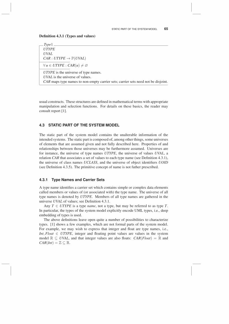
Definition 4.3.1 (Types and values)
Type1UTYPE
UVAL
CAR : UTYPE → P(UVAL)
∀ u ∈ UTYPE : CAR(u) 6= ∅
UTYPE is the universe of type names.
UVAL is the universe of values.
CAR maps type names to non-empty carrier sets; carrier sets need not be disjoint.
usual constructs. These structures are defined in mathematical terms with appropriate
manipulation and selection functions. For details on these basics, the reader may
consult report [1].
4.3 STATIC PART OF THE SYSTEM MODEL
The static part of the system model contains the unalterable information of the
intended systems. The static part is composed of, among other things, some universes
of elements that are assumed given and not fully described here. Properties of and
relationships between those universes may be furthermore assumed. Universes are
for instance, the universe of type names UTYPE, the universe of values UVAL, a
relation CAR that associates a set of values to each type name (see Definition 4.3.1),
the universe of class names UCLASS, and the universe of object identifiers UOID
(see Definition 4.3.5). The primitive concept of name is not futher prescribed.
4.3.1 Type Names and Carrier Sets
A type name identifies a carrier set which contains simple or complex data elements
called members or values of (or associated with) the type name. The universe of all
type names is denoted by UTYPE. Members of all type names are gathered in the
universe UVAL of values; see Definition 4.3.1.
Any T ∈ UTYPE is a type name, not a type, but may be referred to as type T .
In particular, the types of the system model explicitly encode UML types, i.e., deep
embedding of types is used.
The above definitions leave open quite a number of possibilities to characterize
types. [1] shows a few examples, which are not formal parts of the system model.
For example, we may wish to express that integer and float are type names, i.e.,
Int,Float ∈ UTYPE, integer and floating point values are values in the system
model R ⊆ UVAL, and that integer values are also floats: CAR(Float) = R and
CAR(Int) = Z ⊆ R.
66 DEFINITION OF THE SYSTEM MODEL
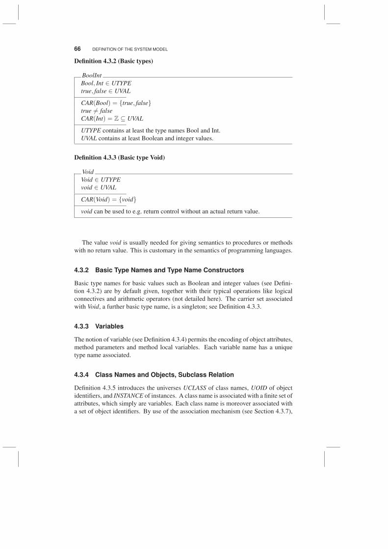
Definition 4.3.2 (Basic types)
BoolInt
Bool, Int ∈ UTYPE
true, false ∈ UVAL
CAR(Bool) = {true, false}true 6= false
CAR(Int) = Z ⊆ UVAL
UTYPE contains at least the type names Bool and Int.
UVAL contains at least Boolean and integer values.
Definition 4.3.3 (Basic type Void)
Void
Void ∈ UTYPE
void ∈ UVAL
CAR(Void) = {void}
void can be used to e.g. return control without an actual return value.
The value void is usually needed for giving semantics to procedures or methods
with no return value. This is customary in the semantics of programming languages.
4.3.2 Basic Type Names and Type Name Constructors
Basic type names for basic values such as Boolean and integer values (see Defini-
tion 4.3.2) are by default given, together with their typical operations like logical
connectives and arithmetic operators (not detailed here). The carrier set associated
with Void, a further basic type name, is a singleton; see Definition 4.3.3.
4.3.3 Variables
The notion of variable (see Definition 4.3.4) permits the encoding of object attributes,
method parameters and method local variables. Each variable name has a unique
type name associated.
4.3.4 Class Names and Objects, Subclass Relation
Definition 4.3.5 introduces the universes UCLASS of class names, UOID of object
identifiers, and INSTANCE of instances. A class name is associated with a finite set of
attributes, which simply are variables. Each class name is moreover associated with
a set of object identifiers. By use of the association mechanism (see Section 4.3.7),
STATIC PART OF THE SYSTEM MODEL 67
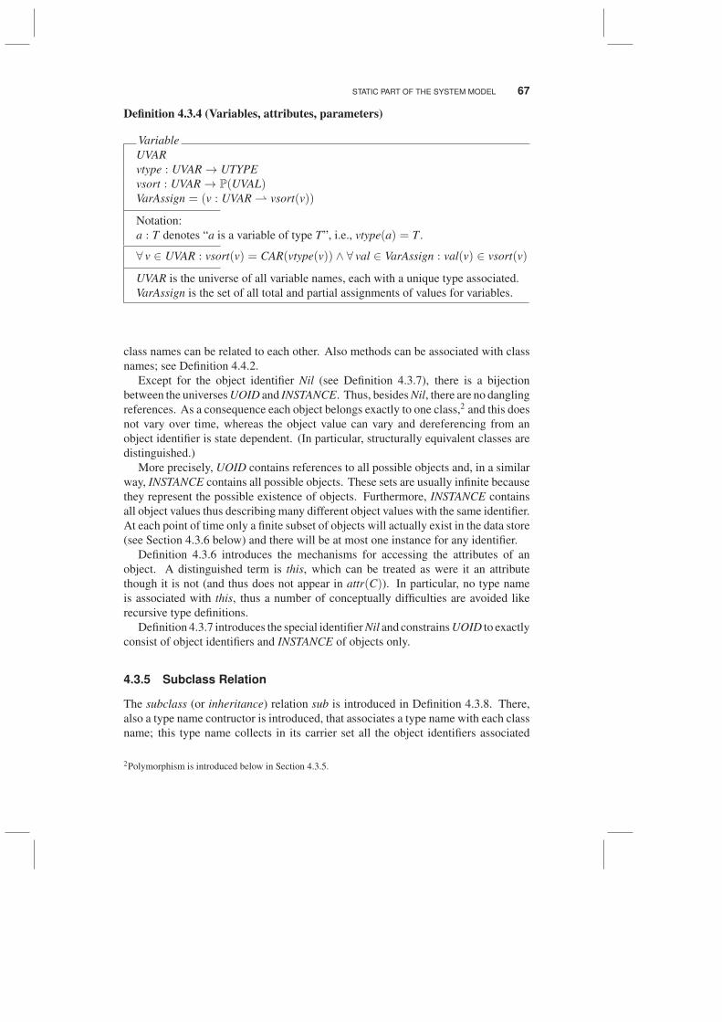
Definition 4.3.4 (Variables, attributes, parameters)
Variable
UVAR
vtype : UVAR → UTYPE
vsort : UVAR → P(UVAL)VarAssign = (v : UVAR ⇀ vsort(v))
Notation:
a : T denotes “a is a variable of type T”, i.e., vtype(a) = T .
∀ v ∈ UVAR : vsort(v) = CAR(vtype(v)) ∧ ∀ val ∈ VarAssign : val(v) ∈ vsort(v)
UVAR is the universe of all variable names, each with a unique type associated.
VarAssign is the set of all total and partial assignments of values for variables.
class names can be related to each other. Also methods can be associated with class
names; see Definition 4.4.2.
Except for the object identifier Nil (see Definition 4.3.7), there is a bijection
between the universes UOID and INSTANCE. Thus, besides Nil, there are no dangling
references. As a consequence each object belongs exactly to one class,2 and this does
not vary over time, whereas the object value can vary and dereferencing from an
object identifier is state dependent. (In particular, structurally equivalent classes are
distinguished.)
More precisely, UOID contains references to all possible objects and, in a similar
way, INSTANCE contains all possible objects. These sets are usually infinite because
they represent the possible existence of objects. Furthermore, INSTANCE contains
all object values thus describing many different object values with the same identifier.
At each point of time only a finite subset of objects will actually exist in the data store
(see Section 4.3.6 below) and there will be at most one instance for any identifier.
Definition 4.3.6 introduces the mechanisms for accessing the attributes of an
object. A distinguished term is this, which can be treated as were it an attribute
though it is not (and thus does not appear in attr(C)). In particular, no type name
is associated with this, thus a number of conceptually difficulties are avoided like
recursive type definitions.
Definition 4.3.7 introduces the special identifier Nil and constrains UOID to exactly
consist of object identifiers and INSTANCE of objects only.
4.3.5 Subclass Relation
The subclass (or inheritance) relation sub is introduced in Definition 4.3.8. There,
also a type name contructor is introduced, that associates a type name with each class
name; this type name collects in its carrier set all the object identifiers associated
2Polymorphism is introduced below in Section 4.3.5.
68 DEFINITION OF THE SYSTEM MODEL
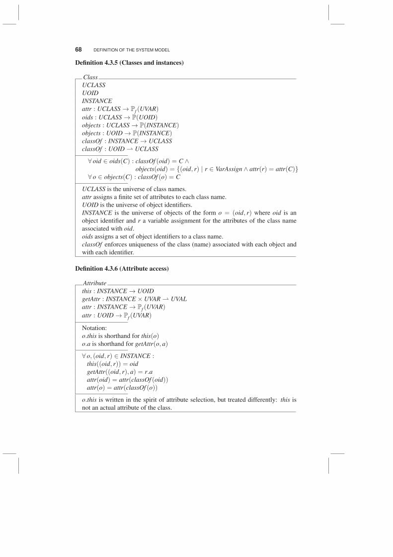
Definition 4.3.5 (Classes and instances)
Class
UCLASS
UOID
INSTANCE
attr : UCLASS → Pf (UVAR)
oids : UCLASS → P(UOID)objects : UCLASS → P(INSTANCE)objects : UOID → P(INSTANCE)classOf : INSTANCE → UCLASS
classOf : UOID ⇀ UCLASS
∀ oid ∈ oids(C) : classOf (oid) = C ∧objects(oid) = {(oid, r) | r ∈ VarAssign ∧ attr(r) = attr(C)}
∀ o ∈ objects(C) : classOf (o) = C
UCLASS is the universe of class names.
attr assigns a finite set of attributes to each class name.
UOID is the universe of object identifiers.
INSTANCE is the universe of objects of the form o = (oid, r) where oid is an
object identifier and r a variable assignment for the attributes of the class name
associated with oid.
oids assigns a set of object identifiers to a class name.
classOf enforces uniqueness of the class (name) associated with each object and
with each identifier.
Definition 4.3.6 (Attribute access)
Attribute
this : INSTANCE → UOID
getAttr : INSTANCE × UVAR ⇀ UVAL
attr : INSTANCE → Pf (UVAR)
attr : UOID → Pf (UVAR)
Notation:
o.this is shorthand for this(o)o.a is shorthand for getAttr(o, a)
∀ o, (oid, r) ∈ INSTANCE :this((oid, r)) = oid
getAttr((oid, r), a) = r.aattr(oid) = attr(classOf (oid))attr(o) = attr(classOf (o))
o.this is written in the spirit of attribute selection, but treated differently: this is
not an actual attribute of the class.
STATIC PART OF THE SYSTEM MODEL 69
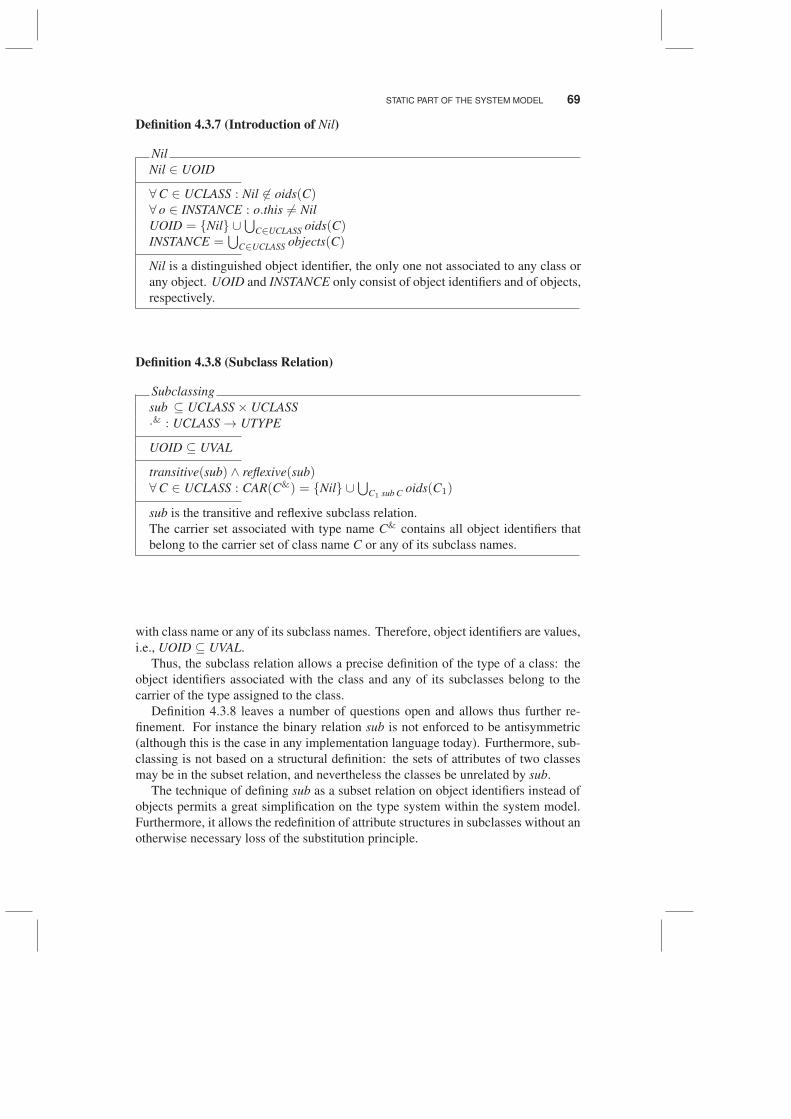
Definition 4.3.7 (Introduction of Nil)
Nil
Nil ∈ UOID
∀C ∈ UCLASS : Nil 6∈ oids(C)∀ o ∈ INSTANCE : o.this 6= Nil
UOID = {Nil} ∪⋃
C∈UCLASS oids(C)INSTANCE =
⋃C∈UCLASS objects(C)
Nil is a distinguished object identifier, the only one not associated to any class or
any object. UOID and INSTANCE only consist of object identifiers and of objects,
respectively.
Definition 4.3.8 (Subclass Relation)
Subclassing
sub ⊆ UCLASS× UCLASS
·& : UCLASS → UTYPE
UOID ⊆ UVAL
transitive(sub) ∧ reflexive(sub)∀C ∈ UCLASS : CAR(C&) = {Nil} ∪
⋃C1 sub C oids(C1)
sub is the transitive and reflexive subclass relation.
The carrier set associated with type name C& contains all object identifiers that
belong to the carrier set of class name C or any of its subclass names.
with class name or any of its subclass names. Therefore, object identifiers are values,
i.e., UOID ⊆ UVAL.
Thus, the subclass relation allows a precise definition of the type of a class: the
object identifiers associated with the class and any of its subclasses belong to the
carrier of the type assigned to the class.
Definition 4.3.8 leaves a number of questions open and allows thus further re-
finement. For instance the binary relation sub is not enforced to be antisymmetric
(although this is the case in any implementation language today). Furthermore, sub-
classing is not based on a structural definition: the sets of attributes of two classes
may be in the subset relation, and nevertheless the classes be unrelated by sub.
The technique of defining sub as a subset relation on object identifiers instead of
objects permits a great simplification on the type system within the system model.
Furthermore, it allows the redefinition of attribute structures in subclasses without an
otherwise necessary loss of the substitution principle.
70 DEFINITION OF THE SYSTEM MODEL
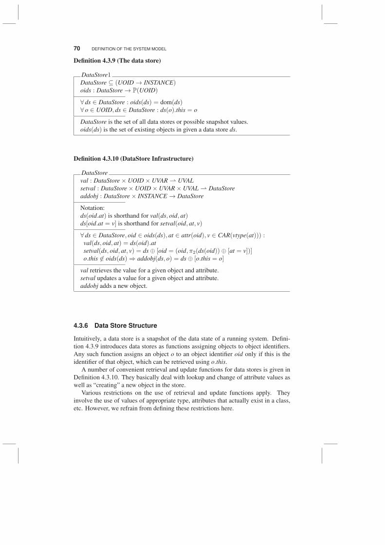
Definition 4.3.9 (The data store)
DataStore1DataStore ⊆ (UOID → INSTANCE)oids : DataStore → P(UOID)
∀ ds ∈ DataStore : oids(ds) = dom(ds)∀ o ∈ UOID, ds ∈ DataStore : ds(o).this = o
DataStore is the set of all data stores or possible snapshot values.
oids(ds) is the set of existing objects in given a data store ds.
Definition 4.3.10 (DataStore Infrastructure)
DataStore
val : DataStore× UOID× UVAR ⇀ UVAL
setval : DataStore× UOID× UVAR× UVAL ⇀ DataStore
addobj : DataStore× INSTANCE → DataStore
Notation:
ds(oid.at) is shorthand for val(ds, oid, at)ds[oid.at = v] is shorthand for setval(oid, at, v)
∀ ds ∈ DataStore, oid ∈ oids(ds), at ∈ attr(oid), v ∈ CAR(vtype(at))) :val(ds, oid, at) = ds(oid).at
setval(ds, oid, at, v) = ds⊕ [oid = (oid, π2(ds(oid))⊕ [at = v])]o.this 6∈ oids(ds)⇒ addobj(ds, o) = ds⊕ [o.this = o]
val retrieves the value for a given object and attribute.
setval updates a value for a given object and attribute.
addobj adds a new object.
4.3.6 Data Store Structure
Intuitively, a data store is a snapshot of the data state of a running system. Defini-
tion 4.3.9 introduces data stores as functions assigning objects to object identifiers.
Any such function assigns an object o to an object identifier oid only if this is the
identifier of that object, which can be retrieved using o.this.
A number of convenient retrieval and update functions for data stores is given in
Definition 4.3.10. They basically deal with lookup and change of attribute values as
well as “creating” a new object in the store.
Various restrictions on the use of retrieval and update functions apply. They
involve the use of values of appropriate type, attributes that actually exist in a class,
etc. However, we refrain from defining these restrictions here.
STATIC PART OF THE SYSTEM MODEL 71
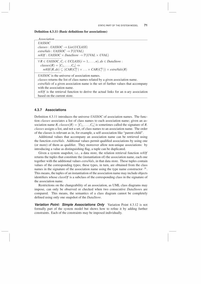
Definition 4.3.11 (Basic definitions for associations)
Association
UASSOC
classes : UASSOC → List(UCLASS)extraVals : UASSOC → P(UVAL)relOf : UASSOC × DataStore → P(UVAL× UVAL)
∀R ∈ UASSOC,Ci ∈ UCLASS(i = 1, . . . , n), ds ∈ DataStore :classes(R) = [C1, . . . ,Cn]⇒
relOf (R, ds) ⊆ (CAR(C&1 )× . . .× CAR(C&
i ))× extraVals(R)
UASSOC is the universe of association names.
classes returns the list of class names related by a given association name.
extraVals of a given association name is the set of further values that accompany
with the association name.
relOf is the retrieval function to derive the actual links for an n-ary association
based on the current store.
4.3.7 Associations
Definition 4.3.11 introduces the universe UASSOC of association names. The func-
tion classes associates a list of class names to each association name; given an as-
sociation name R, classes(R) = [C1, . . . ,Cn] is sometimes called the signature of R.
classes assigns a list, and not a set, of class names to an association name. The order
of the classes is relevant as in, for example, a self-association like “parent-child”.
Additional values that accompany an association name can be retrieved using
the function extraVals. Addtional values permit qualified associations by using one
(or more) of them as qualifier. They moreover allow non-unique associations: by
introducing a value as distinguishing flag, a tuple can be duplicated.
Given a system snapshot, i.e., a data store, the relation retrieval function relOf
returns the tuples that constitute the (instantiation of) the association name, each one
together with the additional values extraVals, in that data store. These tuples contain
values of the corresponding types; these types, in turn, are obtained from the class
names in the signature of the association name using the type name constructor ·&.
This means, the tuples of an instantiation of the association name may include objects
identifiers whose classOf is a subclass of the corresponding class in the signature of
the association name.
Restrictions on the changeability of an association, as UML class diagrams may
impose, can only be observed or checked when two consecutive DataStores are
compared. This means, the semantics of a class diagram cannot be completely
defined using only one snapshot of the DataStore.
Variation Point: Simple Associations Only Variation Point 4.3.12 is not
formally part of the system model but shows how to refine it by adding further
constraints. Each of the constraints may be imposed individually.
72 DEFINITION OF THE SYSTEM MODEL
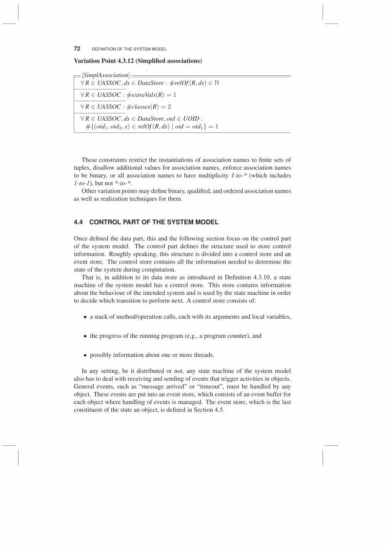
Variation Point 4.3.12 (Simplified associations)
[SimplAssociation]∀R ∈ UASSOC, ds ∈ DataStore : #relOf (R, ds) ∈ N
∀R ∈ UASSOC : #extraVals(R) = 1
∀R ∈ UASSOC : #classes(R) = 2
∀R ∈ UASSOC, ds ∈ DataStore, oid ∈ UOID :#{(oid1, oid2, x) ∈ relOf (R, ds) | oid = oid1} = 1
These constraints restrict the instantiations of association names to finite sets of
tuples, disallow additional values for association names, enforce association names
to be binary, or all association names to have multiplicity 1-to-* (which includes
1-to-1), but not *-to-*.
Other variation points may define binary, qualified, and ordered association names
as well as realization techniques for them.
4.4 CONTROL PART OF THE SYSTEM MODEL
Once defined the data part, this and the following section focus on the control part
of the system model. The control part defines the structure used to store control
information. Roughly speaking, this structure is divided into a control store and an
event store. The control store contains all the information needed to determine the
state of the system during computation.
That is, in addition to its data store as introduced in Definition 4.3.10, a state
machine of the system model has a control store. This store contains information
about the behaviour of the intended system and is used by the state machine in order
to decide which transition to perform next. A control store consists of:
• a stack of method/operation calls, each with its arguments and local variables,
• the progress of the running program (e.g., a program counter), and
• possibly information about one or more threads.
In any setting, be it distributed or not, any state machine of the system model
also has to deal with receiving and sending of events that trigger activities in objects.
General events, such as “message arrived” or “timeout”, must be handled by any
object. These events are put into an event store, which consists of an event buffer for
each object where handling of events is managed. The event store, which is the last
constituent of the state an object, is defined in Section 4.5.
CONTROL PART OF THE SYSTEM MODEL 73
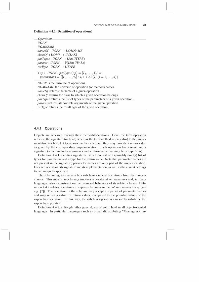
Definition 4.4.1 (Definition of operations)
Operation
UOPN
UOMNAME
nameOf : UOPN → UOMNAME
classOf : UOPN → UCLASS
parTypes : UOPN → List(UTYPE)params : UOPN → P(List(UVAL))resType : UOPN → UTYPE
∀ op ∈ UOPN : parTypes(op) = [T1, . . . , Tn]⇒params(op) = {[v1, . . . , vn] : vi ∈ CAR(Ti)(i = 1, . . . , n)}
UOPN is the universe of operations.
UOMNAME the universe of operation (or method) names.
nameOf returns the name of a given operation.
classOf returns the class to which a given operation belongs.
parTypes returns the list of types of the parameters of a given operation.
params returns all possible arguments of the given operation.
resType returns the result type of the given operation.
4.4.1 Operations
Objects are accessed through their methods/operations. Here, the term operation
refers to the signature (or head) whereas the term method refers (also) to the imple-
mentation (or body). Operations can be called and they may provide a return value
as given by the corresponding implementation. Each operation has a name and a
signature (which includes arguments and a return value that may be of type Void).
Definition 4.4.1 specifies signatures, which consist of a (possibly empty) list of
types for parameters and a type for the return value. Note that parameter names are
not present in the signature; parameter names are only part of the implementation.
For each operation, its signature and its implementation, as well as the class it belongs
to, are uniquely specified.
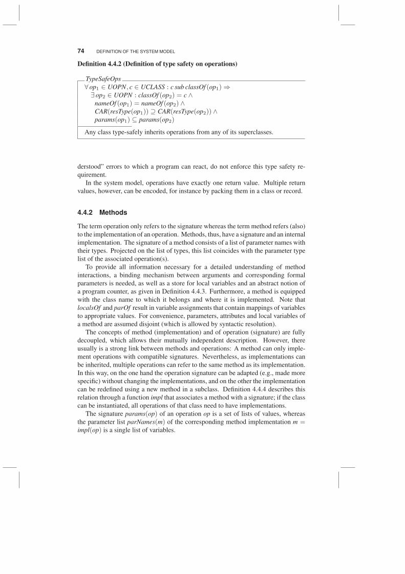
The subclassing mechanism lets subclasses inherit operations from their super-
classes. This means, subclassing imposes a constraint on signatures and, in many
languages, also a constraint on the promised behaviour of its related classes. Defi-
nition 4.4.2 relates operations in super-/subclasses in the co/contra-variant way (see
e.g. [7]). The operation in the subclass may accept a superset of parameter values
and may return a subset of return values, compared to the possible values of the
superclass operation. In this way, the subclass operation can safely substitute the
superclass operation.
Definition 4.4.2, although rather general, needs not to hold in all object-oriented
languages. In particular, languages such as Smalltalk exhibiting “Message not un-
74 DEFINITION OF THE SYSTEM MODEL
Definition 4.4.2 (Definition of type safety on operations)
TypeSafeOps
∀ op1 ∈ UOPN, c ∈ UCLASS : c sub classOf (op1)⇒∃ op2 ∈ UOPN : classOf (op2) = c ∧
nameOf (op1) = nameOf (op2) ∧CAR(resType(op1)) ⊇ CAR(resType(op2)) ∧params(op1) ⊆ params(op2)
Any class type-safely inherits operations from any of its superclasses.
derstood” errors to which a program can react, do not enforce this type safety re-
quirement.
In the system model, operations have exactly one return value. Multiple return
values, however, can be encoded, for instance by packing them in a class or record.
4.4.2 Methods
The term operation only refers to the signature whereas the term method refers (also)
to the implementation of an operation. Methods, thus, have a signature and an internal
implementation. The signature of a method consists of a list of parameter names with
their types. Projected on the list of types, this list coincides with the parameter type
list of the associated operation(s).
To provide all information necessary for a detailed understanding of method
interactions, a binding mechanism between arguments and corresponding formal
parameters is needed, as well as a store for local variables and an abstract notion of
a program counter, as given in Definition 4.4.3. Furthermore, a method is equipped
with the class name to which it belongs and where it is implemented. Note that
localsOf and parOf result in variable assignments that contain mappings of variables
to appropriate values. For convenience, parameters, attributes and local variables of
a method are assumed disjoint (which is allowed by syntactic resolution).
The concepts of method (implementation) and of operation (signature) are fully
decoupled, which allows their mutually independent description. However, there
usually is a strong link between methods and operations: A method can only imple-
ment operations with compatible signatures. Nevertheless, as implementations can
be inherited, multiple operations can refer to the same method as its implementation.
In this way, on the one hand the operation signature can be adapted (e.g., made more
specific) without changing the implementations, and on the other the implementation
can be redefined using a new method in a subclass. Definition 4.4.4 describes this
relation through a function impl that associates a method with a signature; if the class
can be instantiated, all operations of that class need to have implementations.
The signature params(op) of an operation op is a set of lists of values, whereas
the parameter list parNames(m) of the corresponding method implementation m =impl(op) is a single list of variables.
CONTROL PART OF THE SYSTEM MODEL 75
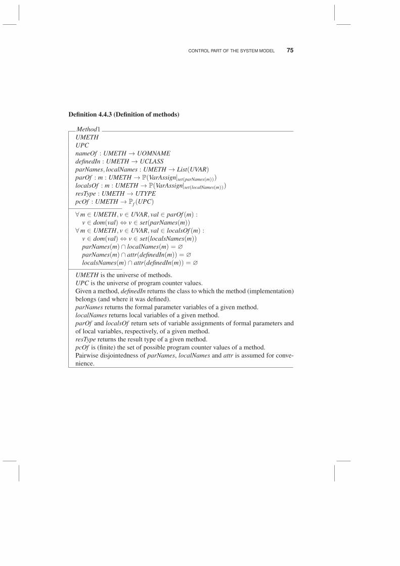
Definition 4.4.3 (Definition of methods)
Method1UMETH
UPC
nameOf : UMETH → UOMNAME
definedIn : UMETH → UCLASS
parNames, localNames : UMETH → List(UVAR)parOf : m : UMETH → P(VarAssign|set(parNames(m)))localsOf : m : UMETH → P(VarAssign|set(localNames(m)))resType : UMETH → UTYPE
pcOf : UMETH → Pf (UPC)
∀m ∈ UMETH, v ∈ UVAR, val ∈ parOf (m) :v ∈ dom(val)⇔ v ∈ set(parNames(m))
∀m ∈ UMETH, v ∈ UVAR, val ∈ localsOf (m) :v ∈ dom(val)⇔ v ∈ set(localsNames(m))parNames(m) ∩ localNames(m) = ∅
parNames(m) ∩ attr(definedIn(m)) = ∅
localsNames(m) ∩ attr(definedIn(m)) = ∅
UMETH is the universe of methods.
UPC is the universe of program counter values.
Given a method, definedIn returns the class to which the method (implementation)
belongs (and where it was defined).
parNames returns the formal parameter variables of a given method.
localNames returns local variables of a given method.
parOf and localsOf return sets of variable assignments of formal parameters and
of local variables, respectively, of a given method.
resType returns the result type of a given method.
pcOf is (finite) the set of possible program counter values of a method.
Pairwise disjointedness of parNames, localNames and attr is assumed for conve-
nience.
76 DEFINITION OF THE SYSTEM MODEL
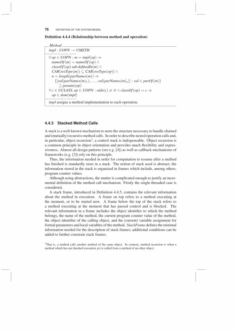
Definition 4.4.4 (Relationship between method and operation)
Method
impl : UOPN ⇀ UMETH
∀ op ∈ UOPN : m = impl(op)⇒nameOf (m) = nameOf (op) ∧classOf (op) sub definedIn(m) ∧CAR(resType(m)) ⊆ CAR(resType(op)) ∧n = length(parNames(m))⇒{[val(parNames(m)1), . . . , val(parNames(m)n)] : val ∈ parOf (m)}⊇ params(op)
∀ c ∈ UCLASS, op ∈ UOPN : oids(c) 6= ∅ ∧ classOf (op) = c ⇒op ∈ dom(impl)
impl assigns a method implementation to each operation.
4.4.3 Stacked Method Calls
A stack is a well-known mechanism to store the structure necessary to handle chained
and (mutually) recursive method calls. In order to describe nested operation calls and,
in particular, object recursion3, a control stack is indispensable. Object recursion is
a common principle in object orientation and provides much flexibility and expres-
siveness. Almost all design patterns (see e.g. [4]) as well as callback-mechanisms of
frameworks (e.g. [3]) rely on this principle.
Thus, the information needed in order for computation to resume after a method
has finished is standardly store in a stack. The notion of stack used is abstract, the
information stored in the stack is organized in frames which include, among others,
program counter values.
Although using abstractions, the matter is complicated enough to justify an incre-
mental definition of the method call mechanism. Firstly the single-threaded case is
considered.
A stack frame, introduced in Definition 4.4.5, contains the relevant information
about the method in execution. A frame on top refers to a method executing at
the moment, or to be started now. A frame below the top of the stack refers to
a method executing at the moment that has passed control and is blocked. The
relevant information in a frame includes the object identifier to which the method
belongs, the name of the method, the current program counter value of the method,
the object identifier of the calling object, and the (current) variable assignment for
formal parameters and local variables of the method. StackFrame defines the minimal
information needed for the description of stack frames; additional conditions can be
added to further constrain stack frames.
3That is, a method calls another method of the same object. In contrast, method recursion is when a
method which has not finished execution yet is called from a method of an other object.
CONTROL PART OF THE SYSTEM MODEL 77
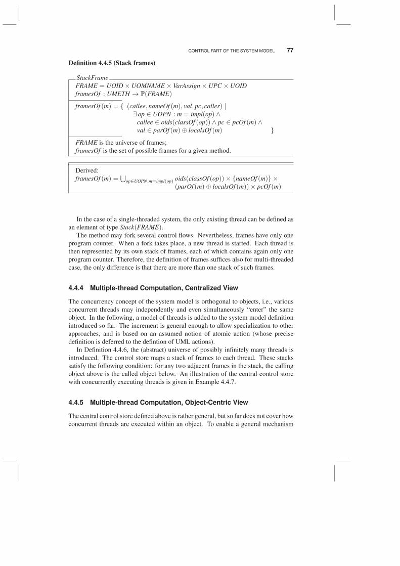
Definition 4.4.5 (Stack frames)
StackFrame
FRAME = UOID× UOMNAME × VarAssign× UPC × UOID
framesOf : UMETH → P(FRAME)
framesOf (m) = { (callee, nameOf (m), val, pc, caller) |∃ op ∈ UOPN : m = impl(op) ∧
callee ∈ oids(classOf (op)) ∧ pc ∈ pcOf (m) ∧val ∈ parOf (m)⊕ localsOf (m) }
FRAME is the universe of frames;
framesOf is the set of possible frames for a given method.
Derived:
framesOf (m) =⋃
op∈UOPN,m=impl(op) oids(classOf (op))× {nameOf (m)} ×(parOf (m)⊕ localsOf (m))× pcOf (m)
In the case of a single-threaded system, the only existing thread can be defined as
an element of type Stack(FRAME).The method may fork several control flows. Nevertheless, frames have only one
program counter. When a fork takes place, a new thread is started. Each thread is
then represented by its own stack of frames, each of which contains again only one
program counter. Therefore, the definition of frames suffices also for multi-threaded
case, the only difference is that there are more than one stack of such frames.
4.4.4 Multiple-thread Computation, Centralized View
The concurrency concept of the system model is orthogonal to objects, i.e., various
concurrent threads may independently and even simultaneously “enter” the same
object. In the following, a model of threads is added to the system model definition
introduced so far. The increment is general enough to allow specialization to other
approaches, and is based on an assumed notion of atomic action (whose precise
definition is deferred to the defintion of UML actions).
In Definition 4.4.6, the (abstract) universe of possibly infinitely many threads is
introduced. The control store maps a stack of frames to each thread. These stacks
satisfy the following condition: for any two adjacent frames in the stack, the calling
object above is the called object below. An illustration of the central control store
with concurrently executing threads is given in Example 4.4.7.
4.4.5 Multiple-thread Computation, Object-Centric View
The central control store defined above is rather general, but so far does not cover how
concurrent threads are executed within an object. To enable a general mechanism
78 DEFINITION OF THE SYSTEM MODEL
Definition 4.4.6 (The control store in centralized version)
Thread
UTHREAD
CentralControlStore ⊆ (UTHREAD → Stack(FRAME))
∀ ccs ∈ CentralControlStore, t ∈ UTHREAD :∀ n < #ccs(t) : ∃ oid ∈ UOID :
ccs(t)[n] = (oid, ∗, ∗, ∗, ∗) ∧ ccs(t)[n + 1] = (∗, ∗, ∗, ∗, oid)
UTHREAD is the universe of threads.
CentralControlStore assigns a stack of frames to each thread.
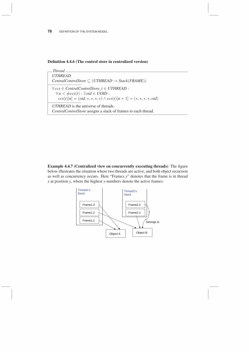
Example 4.4.7 (Centralized view on concurrently executing threads) The figure
below illustrates the situation where two threads are active, and both object recursion
as well as concurrency occurs. Here “Framex.y” denotes that the frame is in thread
x at position y, where the highest y-numbers denote the active frames:
����������
��� ����
��� ����
��� � ��
����� ���
�������
����������
��������
����� ��
���������
�������
����������
CONTROL PART OF THE SYSTEM MODEL 79
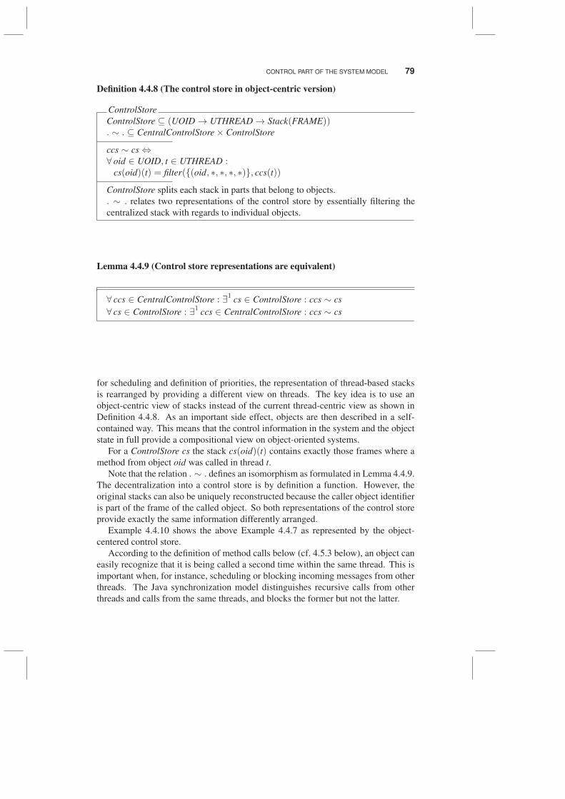
Definition 4.4.8 (The control store in object-centric version)
ControlStore
ControlStore ⊆ (UOID → UTHREAD → Stack(FRAME)). ∼ . ⊆ CentralControlStore× ControlStore
ccs ∼ cs ⇔∀ oid ∈ UOID, t ∈ UTHREAD :
cs(oid)(t) = filter({(oid, ∗, ∗, ∗, ∗)}, ccs(t))
ControlStore splits each stack in parts that belong to objects.
. ∼ . relates two representations of the control store by essentially filtering the
centralized stack with regards to individual objects.
Lemma 4.4.9 (Control store representations are equivalent)
∀ ccs ∈ CentralControlStore : ∃1
cs ∈ ControlStore : ccs ∼ cs
∀ cs ∈ ControlStore : ∃1
ccs ∈ CentralControlStore : ccs ∼ cs
for scheduling and definition of priorities, the representation of thread-based stacks
is rearranged by providing a different view on threads. The key idea is to use an
object-centric view of stacks instead of the current thread-centric view as shown in
Definition 4.4.8. As an important side effect, objects are then described in a self-
contained way. This means that the control information in the system and the object
state in full provide a compositional view on object-oriented systems.
For a ControlStore cs the stack cs(oid)(t) contains exactly those frames where a
method from object oid was called in thread t.
Note that the relation . ∼ . defines an isomorphism as formulated in Lemma 4.4.9.
The decentralization into a control store is by definition a function. However, the
original stacks can also be uniquely reconstructed because the caller object identifier
is part of the frame of the called object. So both representations of the control store
provide exactly the same information differently arranged.
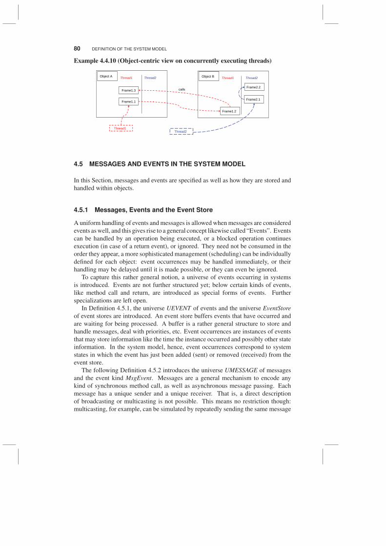
Example 4.4.10 shows the above Example 4.4.7 as represented by the object-
centered control store.
According to the definition of method calls below (cf. 4.5.3 below), an object can
easily recognize that it is being called a second time within the same thread. This is
important when, for instance, scheduling or blocking incoming messages from other
threads. The Java synchronization model distinguishes recursive calls from other
threads and calls from the same threads, and blocks the former but not the latter.
80 DEFINITION OF THE SYSTEM MODEL
Example 4.4.10 (Object-centric view on concurrently executing threads)
��������
������
������
��������
��������
��������� �������� ������
��������� ��������
��������
��������
������
�����
4.5 MESSAGES AND EVENTS IN THE SYSTEM MODEL
In this Section, messages and events are specified as well as how they are stored and
handled within objects.
4.5.1 Messages, Events and the Event Store
A uniform handling of events and messages is allowed when messages are considered
events as well, and this gives rise to a general concept likewise called “Events”. Events
can be handled by an operation being executed, or a blocked operation continues
execution (in case of a return event), or ignored. They need not be consumed in the
order they appear, a more sophisticated management (scheduling) can be individually
defined for each object: event occurrences may be handled immediately, or their
handling may be delayed until it is made possible, or they can even be ignored.
To capture this rather general notion, a universe of events occurring in systems
is introduced. Events are not further structured yet; below certain kinds of events,
like method call and return, are introduced as special forms of events. Further
specializations are left open.
In Definition 4.5.1, the universe UEVENT of events and the universe EventStore
of event stores are introduced. An event store buffers events that have occurred and
are waiting for being processed. A buffer is a rather general structure to store and
handle messages, deal with priorities, etc. Event occurrences are instances of events
that may store information like the time the instance occurred and possibly other state
information. In the system model, hence, event occurrences correspond to system
states in which the event has just been added (sent) or removed (received) from the
event store.
The following Definition 4.5.2 introduces the universe UMESSAGE of messages
and the event kind MsgEvent. Messages are a general mechanism to encode any
kind of synchronous method call, as well as asynchronous message passing. Each
message has a unique sender and a unique receiver. That is, a direct description
of broadcasting or multicasting is not possible. This means no restriction though:
multicasting, for example, can be simulated by repeatedly sending the same message
MESSAGES AND EVENTS IN THE SYSTEM MODEL 81
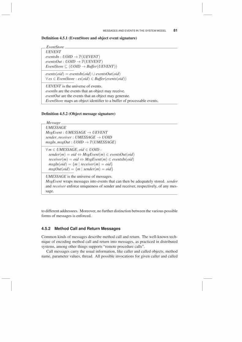
Definition 4.5.1 (EventStore and object event signature)
EventStore
UEVENT
eventsIn : UOID → P(UEVENT)eventsOut : UOID → P(UEVENT)EventStore ⊆ (UOID → Buffer(UEVENT))
events(oid) = eventsIn(oid) ∪ eventsOut(oid)∀ es ∈ EventStore : es(oid) ∈ Buffer(events(oid))
UEVENT is the universe of events.
eventIn are the events that an object may receive.
eventOut are the events that an object may generate.
EventStore maps an object identifier to a buffer of processable events.
Definition 4.5.2 (Object message signature)
Message
UMESSAGE
MsgEvent : UMESSAGE → UEVENT
sender, receiver : UMESSAGE → UOID
msgIn,msgOut : UOID → P(UMESSAGE)
∀m ∈ UMESSAGE, oid ∈ UOID :sender(m) = oid ⇔ MsgEvent(m) ∈ eventsOut(oid)receiver(m) = oid ⇔ MsgEvent(m) ∈ eventsIn(oid)msgIn(oid) = {m | receiver(m) = oid}msgOut(oid) = {m | sender(m) = oid}
UMESSAGE is the universe of messages.
MsgEvent wraps messages into events that can then be adequately stored. sender
and receiver enforce uniqueness of sender and receiver, respectively, of any mes-
sage.
to different addressees. Moreover, no further distinction between the various possible
forms of messages is enforced.
4.5.2 Method Call and Return Messages
Common kinds of messages describe method call and return. The well-known tech-
nique of encoding method call and return into messages, as practiced in distributed
systems, among other things supports “remote procedure calls”.
Call messages carry the usual information, like caller and called objects, method
name, parameter values, thread. All possible invocations for given caller and called
82 DEFINITION OF THE SYSTEM MODEL
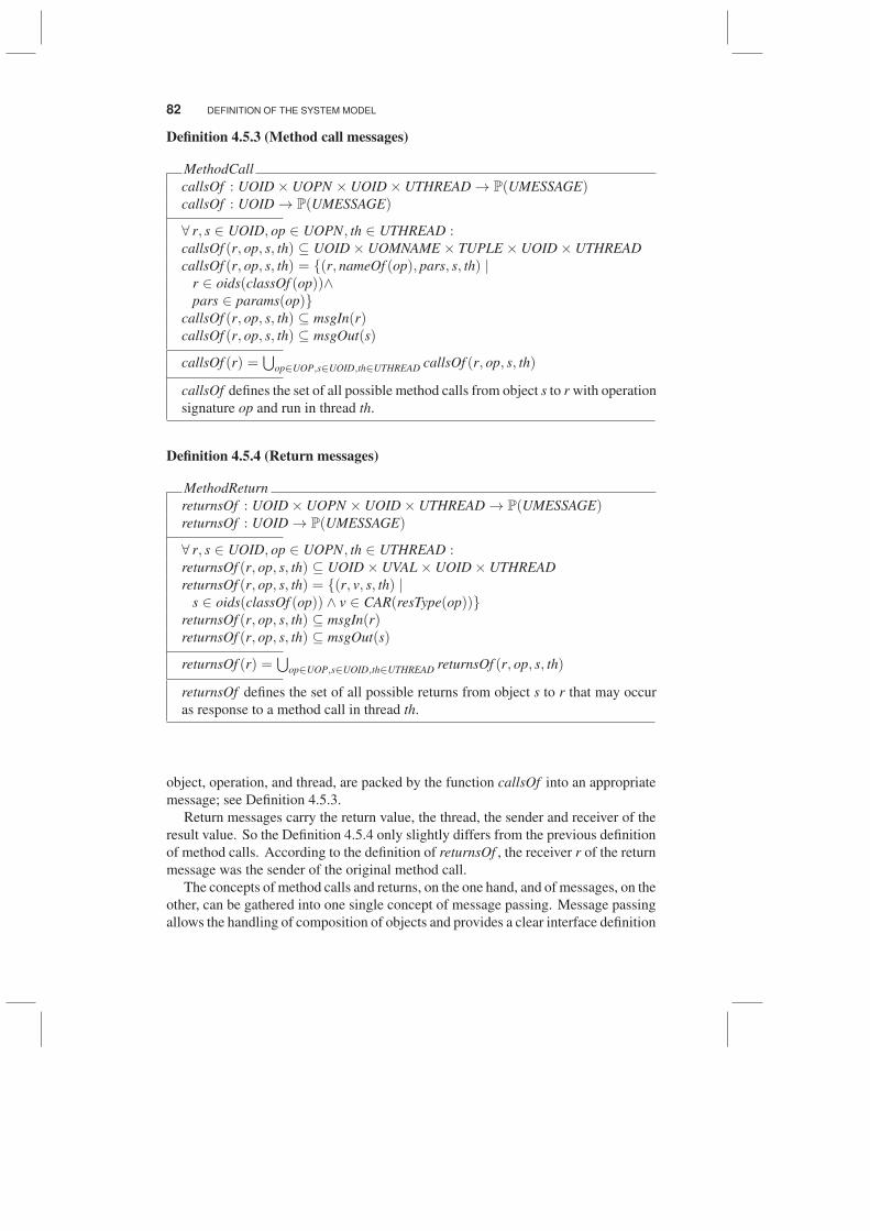
Definition 4.5.3 (Method call messages)
MethodCall
callsOf : UOID× UOPN × UOID× UTHREAD → P(UMESSAGE)callsOf : UOID → P(UMESSAGE)
∀ r, s ∈ UOID, op ∈ UOPN, th ∈ UTHREAD :callsOf (r, op, s, th) ⊆ UOID× UOMNAME × TUPLE × UOID× UTHREAD
callsOf (r, op, s, th) = {(r, nameOf (op), pars, s, th) |r ∈ oids(classOf (op))∧pars ∈ params(op)}
callsOf (r, op, s, th) ⊆ msgIn(r)callsOf (r, op, s, th) ⊆ msgOut(s)
callsOf (r) =⋃
op∈UOP,s∈UOID,th∈UTHREAD callsOf (r, op, s, th)
callsOf defines the set of all possible method calls from object s to r with operation
signature op and run in thread th.
Definition 4.5.4 (Return messages)
MethodReturn
returnsOf : UOID× UOPN × UOID× UTHREAD → P(UMESSAGE)returnsOf : UOID → P(UMESSAGE)
∀ r, s ∈ UOID, op ∈ UOPN, th ∈ UTHREAD :returnsOf (r, op, s, th) ⊆ UOID× UVAL× UOID× UTHREAD
returnsOf (r, op, s, th) = {(r, v, s, th) |s ∈ oids(classOf (op)) ∧ v ∈ CAR(resType(op))}
returnsOf (r, op, s, th) ⊆ msgIn(r)returnsOf (r, op, s, th) ⊆ msgOut(s)
returnsOf (r) =⋃
op∈UOP,s∈UOID,th∈UTHREAD returnsOf (r, op, s, th)
returnsOf defines the set of all possible returns from object s to r that may occur
as response to a method call in thread th.
object, operation, and thread, are packed by the function callsOf into an appropriate
message; see Definition 4.5.3.
Return messages carry the return value, the thread, the sender and receiver of the
result value. So the Definition 4.5.4 only slightly differs from the previous definition
of method calls. According to the definition of returnsOf , the receiver r of the return
message was the sender of the original method call.
The concepts of method calls and returns, on the one hand, and of messages, on the
other, can be gathered into one single concept of message passing. Message passing
allows the handling of composition of objects and provides a clear interface definition
OBJECT STATE 83
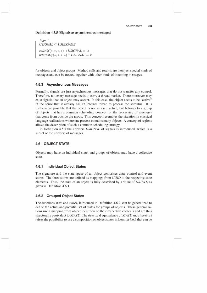
Definition 4.5.5 (Signals as asynchronous messages)
Signal
USIGNAL ⊆ UMESSAGE
callsOf (∗, ∗, ∗, ∗) ∩ USIGNAL = ∅
returnsOf (∗, ∗, ∗, ∗) ∩ USIGNAL = ∅
for objects and object groups. Method calls and returns are then just special kinds of
messages and can be treated together with other kinds of incoming messages.
4.5.3 Asynchronous Messages
Formally, signals are just asynchronous messages that do not transfer any control.
Therefore, not every message needs to carry a thread marker. There moreover may
exist signals that an object may accept. In this case, the object needs to be “active”
in the sense that it already has an internal thread to process the stimulus. It is
furthermore possible that the object is not in itself active, but belongs to a group
of objects that has a common scheduling concept for the processing of messages
that come from outside the group. This concept resembles the situation in classical
language realizations where one process contains many objects. A concept of regions
allows the description of such a common scheduling strategy.
In Definition 4.5.5 the universe USIGNAL of signals is introduced, which is a
subset of the universe of messages.
4.6 OBJECT STATE
Objects may have an individual state, and groups of objects may have a collective
state.
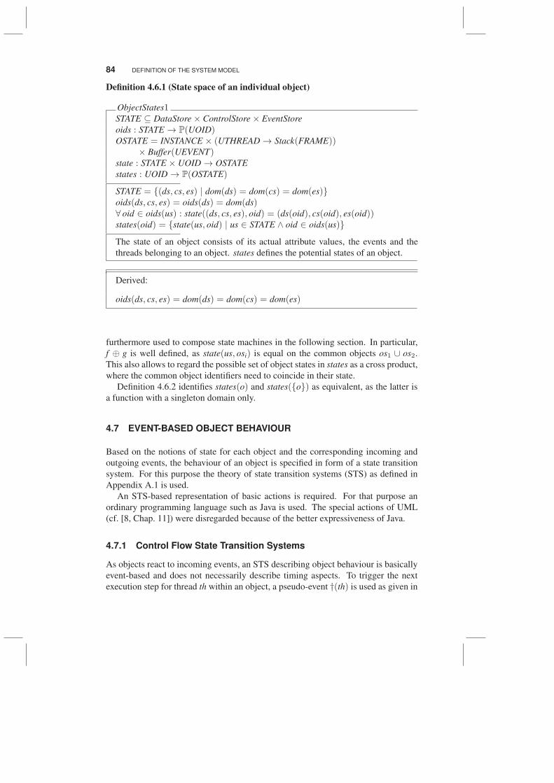
4.6.1 Individual Object States
The signature and the state space of an object comprises data, control and event
stores. The three stores are defined as mappings from UOID to the respective state
elements. Thus, the state of an object is fully described by a value of OSTATE as
given in Definition 4.6.1.
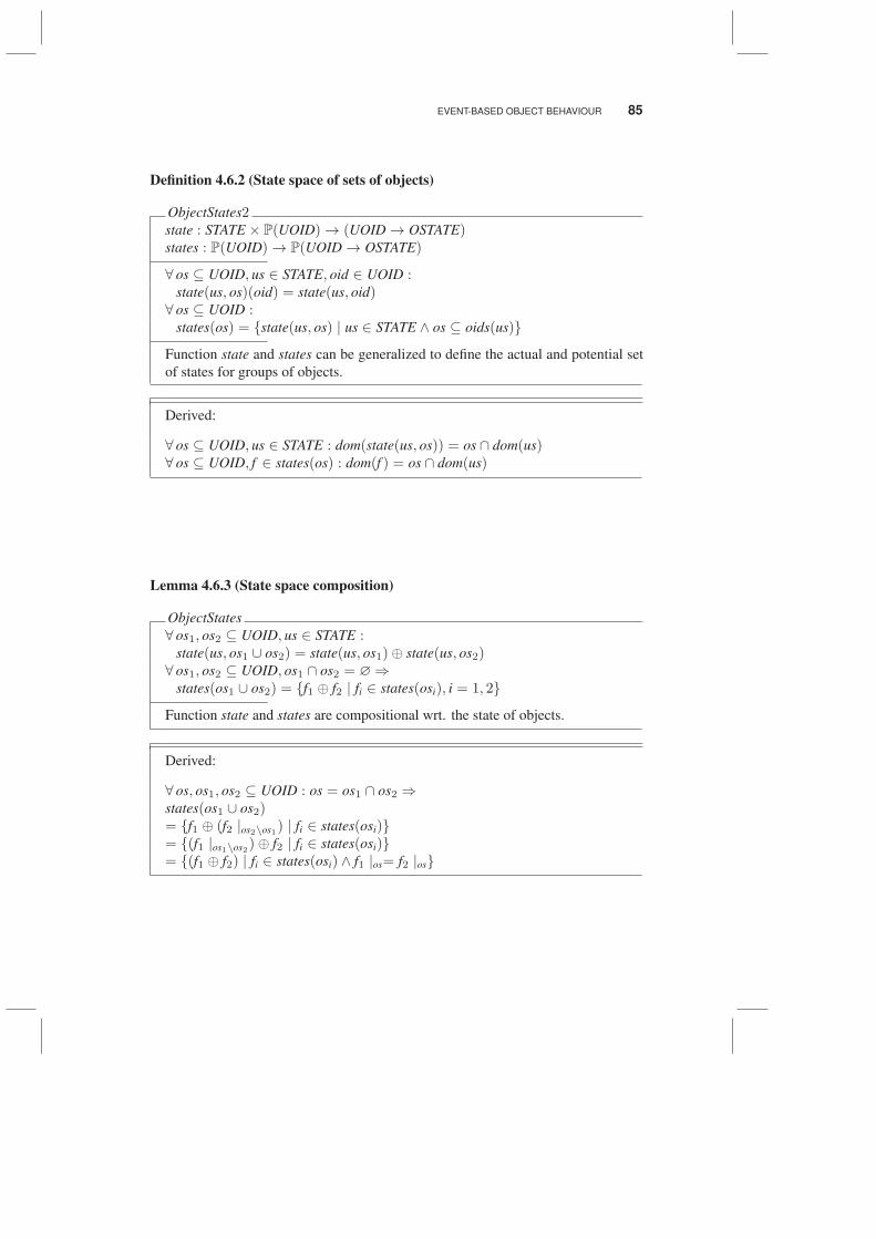
4.6.2 Grouped Object States
The functions state and states, introduced in Definition 4.6.2, can be generalized to
define the actual and potential set of states for groups of objects. These generaliza-
tions use a mapping from object identifiers to their respective contents and are thus
structurally equivalent to STATE. The structural equivalence of STATE and states(os)raises the possibility to use a composition on object states in Lemma 4.6.3 that can be
84 DEFINITION OF THE SYSTEM MODEL
Definition 4.6.1 (State space of an individual object)
ObjectStates1STATE ⊆ DataStore× ControlStore× EventStore
oids : STATE → P(UOID)OSTATE = INSTANCE × (UTHREAD → Stack(FRAME))
× Buffer(UEVENT)state : STATE × UOID → OSTATE
states : UOID → P(OSTATE)
STATE = {(ds, cs, es) | dom(ds) = dom(cs) = dom(es)}oids(ds, cs, es) = oids(ds) = dom(ds)∀ oid ∈ oids(us) : state((ds, cs, es), oid) = (ds(oid), cs(oid), es(oid))states(oid) = {state(us, oid) | us ∈ STATE ∧ oid ∈ oids(us)}
The state of an object consists of its actual attribute values, the events and the
threads belonging to an object. states defines the potential states of an object.
Derived:
oids(ds, cs, es) = dom(ds) = dom(cs) = dom(es)
furthermore used to compose state machines in the following section. In particular,
f ⊕ g is well defined, as state(us, osi) is equal on the common objects os1 ∪ os2.
This also allows to regard the possible set of object states in states as a cross product,
where the common object identifiers need to coincide in their state.
Definition 4.6.2 identifies states(o) and states({o}) as equivalent, as the latter is
a function with a singleton domain only.
4.7 EVENT-BASED OBJECT BEHAVIOUR
Based on the notions of state for each object and the corresponding incoming and
outgoing events, the behaviour of an object is specified in form of a state transition
system. For this purpose the theory of state transition systems (STS) as defined in
Appendix A.1 is used.
An STS-based representation of basic actions is required. For that purpose an
ordinary programming language such as Java is used. The special actions of UML
(cf. [8, Chap. 11]) were disregarded because of the better expressiveness of Java.
4.7.1 Control Flow State Transition Systems
As objects react to incoming events, an STS describing object behaviour is basically
event-based and does not necessarily describe timing aspects. To trigger the next
execution step for thread th within an object, a pseudo-event †(th) is used as given in
EVENT-BASED OBJECT BEHAVIOUR 85
Definition 4.6.2 (State space of sets of objects)
ObjectStates2state : STATE × P(UOID)→ (UOID → OSTATE)states : P(UOID)→ P(UOID → OSTATE)
∀ os ⊆ UOID, us ∈ STATE, oid ∈ UOID :state(us, os)(oid) = state(us, oid)∀ os ⊆ UOID :
states(os) = {state(us, os) | us ∈ STATE ∧ os ⊆ oids(us)}
Function state and states can be generalized to define the actual and potential set
of states for groups of objects.
Derived:
∀ os ⊆ UOID, us ∈ STATE : dom(state(us, os)) = os ∩ dom(us)∀ os ⊆ UOID, f ∈ states(os) : dom(f ) = os ∩ dom(us)
Lemma 4.6.3 (State space composition)
ObjectStates
∀ os1, os2 ⊆ UOID, us ∈ STATE :state(us, os1 ∪ os2) = state(us, os1)⊕ state(us, os2)∀ os1, os2 ⊆ UOID, os1 ∩ os2 = ∅⇒
states(os1 ∪ os2) = {f1 ⊕ f2 | fi ∈ states(osi), i = 1, 2}
Function state and states are compositional wrt. the state of objects.
Derived:
∀ os, os1, os2 ⊆ UOID : os = os1 ∩ os2 ⇒states(os1 ∪ os2)= {f1 ⊕ (f2 |os2\os1) | fi ∈ states(osi)}= {(f1 |os1\os2)⊕ f2 | fi ∈ states(osi)}= {(f1 ⊕ f2) | fi ∈ states(osi) ∧ f1 |os= f2 |os}
86 DEFINITION OF THE SYSTEM MODEL
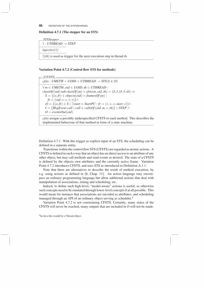
Definition 4.7.1 (The stepper for an STS)
STSStepper
† : UTHREAD → STEP
injective(†)
†(th) is used as trigger for the next execution step in thread th.
Variation Point 4.7.2 (Control flow STS for methods)
[CFSTS]cfsts : UMETH × UOID× UTHREAD ⇀ STS(S, I,O)
∀m ∈ UMETH, oid ∈ UOID, th ∈ UTHREAD :classOf (oid) sub classOf (m) ∧ cfsts(m, oid, th) = (S, I,O, δ, s0)⇒
S = {(o, fr) ∈ objects(oid)× framesOf (m) |fr = (oid, ∗, ∗, ∗, ∗)}∧
s0 = {(o, fr) ∈ S | ∃ start ∈ StartPC : fr = (∗, ∗, ∗, start, ∗)}∧I = {MsgEvent call | call ∈ callsOf (oid,m, ∗, th)} ∪ STEP ∧O = eventsOut(oid)
cfsts assigns a possibly underspecified CFSTS to each method. This describes the
implemented behaviour of that method in form of a state machine.
Definition 4.7.1. With this trigger as explicit input of an STS, the scheduling can be
defined in a separate entity.
Transitions within the control flow STS (CFSTS) are regarded as atomic actions. A
CFSTS is defined in such a way that an object has no direct access to an attribute of any
other object, but may call methods and send events as desired. The state of a CFSTS
is defined by the objects own attributes and the currently active frame. Variation
Point 4.7.2 introduces CFSTS, and uses STS as introduced in Definition A.1.1.
Note that there are alternatives to describe the result of method execution, by
e.g. using actions as defined in [8, Chap. 11]. An action language may encom-
pass an ordinary programming language but allow additional actions that deal with
manipulation of associations, timing and scheduling, etc.
Indeed, to define such high-level, “model-aware” actions is useful, as otherwise
such concepts need to be emulated through lower-level concepts if at all possible. This
would mean for instance that associations are encoded as attributes, and scheduling
managed through an API of an ordinary object serving as scheduler.4
Variation Point 4.7.2 is not constraining CFSTS. Certainly, many states of the
CFSTS will never be reached, many outputs that are included in O will not be made.
4In Java this would be a Thread object.
EVENT-BASED OBJECT BEHAVIOUR 87
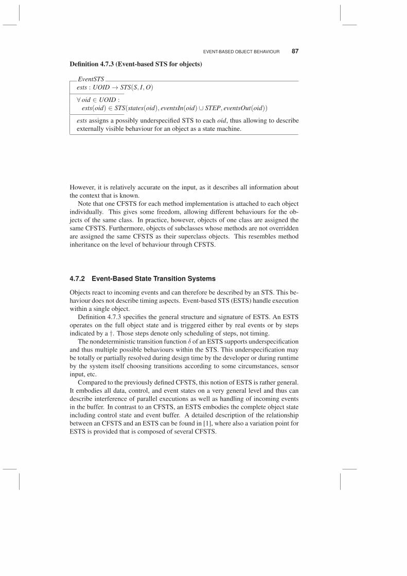
Definition 4.7.3 (Event-based STS for objects)
EventSTS
ests : UOID → STS(S, I,O)
∀ oid ∈ UOID :ests(oid) ∈ STS(states(oid), eventsIn(oid) ∪ STEP, eventsOut(oid))
ests assigns a possibly underspecified STS to each oid, thus allowing to describe
externally visible behaviour for an object as a state machine.
However, it is relatively accurate on the input, as it describes all information about
the context that is known.
Note that one CFSTS for each method implementation is attached to each object
individually. This gives some freedom, allowing different behaviours for the ob-
jects of the same class. In practice, however, objects of one class are assigned the
same CFSTS. Furthermore, objects of subclasses whose methods are not overridden
are assigned the same CFSTS as their superclass objects. This resembles method
inheritance on the level of behaviour through CFSTS.
4.7.2 Event-Based State Transition Systems
Objects react to incoming events and can therefore be described by an STS. This be-
haviour does not describe timing aspects. Event-based STS (ESTS) handle execution
within a single object.
Definition 4.7.3 specifies the general structure and signature of ESTS. An ESTS
operates on the full object state and is triggered either by real events or by steps
indicated by a †. Those steps denote only scheduling of steps, not timing.
The nondeterministic transition function δ of an ESTS supports underspecification
and thus multiple possible behaviours within the STS. This underspecification may
be totally or partially resolved during design time by the developer or during runtime
by the system itself choosing transitions according to some circumstances, sensor
input, etc.
Compared to the previously defined CFSTS, this notion of ESTS is rather general.
It embodies all data, control, and event states on a very general level and thus can
describe interference of parallel executions as well as handling of incoming events
in the buffer. In contrast to an CFSTS, an ESTS embodies the complete object state
including control state and event buffer. A detailed description of the relationship
between an CFSTS and an ESTS can be found in [1], where also a variation point for
ESTS is provided that is composed of several CFSTS.
88 DEFINITION OF THE SYSTEM MODEL
4.8 TIMED OBJECT BEHAVIOUR
This section presents the time-aware version of STS, called timed STS (TSTS) as
defined in Appendix A.2. TSTS allow the description of individual object behaviour
and composition thereof.
A discrete global time is assumed available. Each step of transition of the TSTS
corresponds to a progress of one time unit. A system executes in steps, each step
consumes a fixed amount of time. TSTS are transition systems that deal with this
paradigm. Roughly speaking, in each step a finite set of input events is provided to a
TSTS, and a finite set of output events is produced by the TSTS.
As a further mechanism, communication channels allow the description of the in-
teraction (communication flow) between parts of the objects and thus of the behaviour
of objects on a very fine-grained level.
As a general result, a complete description of how systems are decomposed into
objects is provided, as well as what states objects may have, and how objects interact.
4.8.1 Object Behaviour in the System Model
In the system model, the object and component instances cooperate by asynchronous
message passing. Method invocation is already modeled by the exchange of two
events, the method invocation event and the method return event.
Communication between objects is dealt with by channels. A communication
channel is a unidirectional communication connection between two objects. The
system model defines a universe UCN of channels and leaves open how many channels
are used between objects.
Each channel has a name, e.g., c ∈ UCN, and the type of events that may flow
through c is given by csort(c). Each object has a number of incoming and outgoing
channels, and each event is associated with the channel through which it flows; see
Definition 4.8.1.
As an important consequence of the above definitions, each channel is the in the
output signature of only one object, since events are not only associated to a channel
but also to its originating object. This ensures the applicability of composition
techniques for TSTS, which only work if the output channels of composed objects
are disjoint.
Based on channels and their type, the behaviour of a single object is defined in
Definition 4.8.2. This definition is based on the assumption of a time granularity fine
enough to ensure the independence of the output in one step from the input received
in that step. In this way, strong causality between input and output is preserved. The
composition of state machines is moreover simplified since feedback within one time
unit is ruled out and thus causal inconsistencies are avoided. The actual (real-)time
occurrence of events can be abstracted away, thus only the untimed behaviour of
objects needs be considered.
Definition 4.8.3 provides a flexible concept of components including, e.g., classical
sequential systems (in this case, there is only one input and one output channel). Input
and output flow of events can further restricted allowing the reception or the dispatch
TIMED OBJECT BEHAVIOUR 89
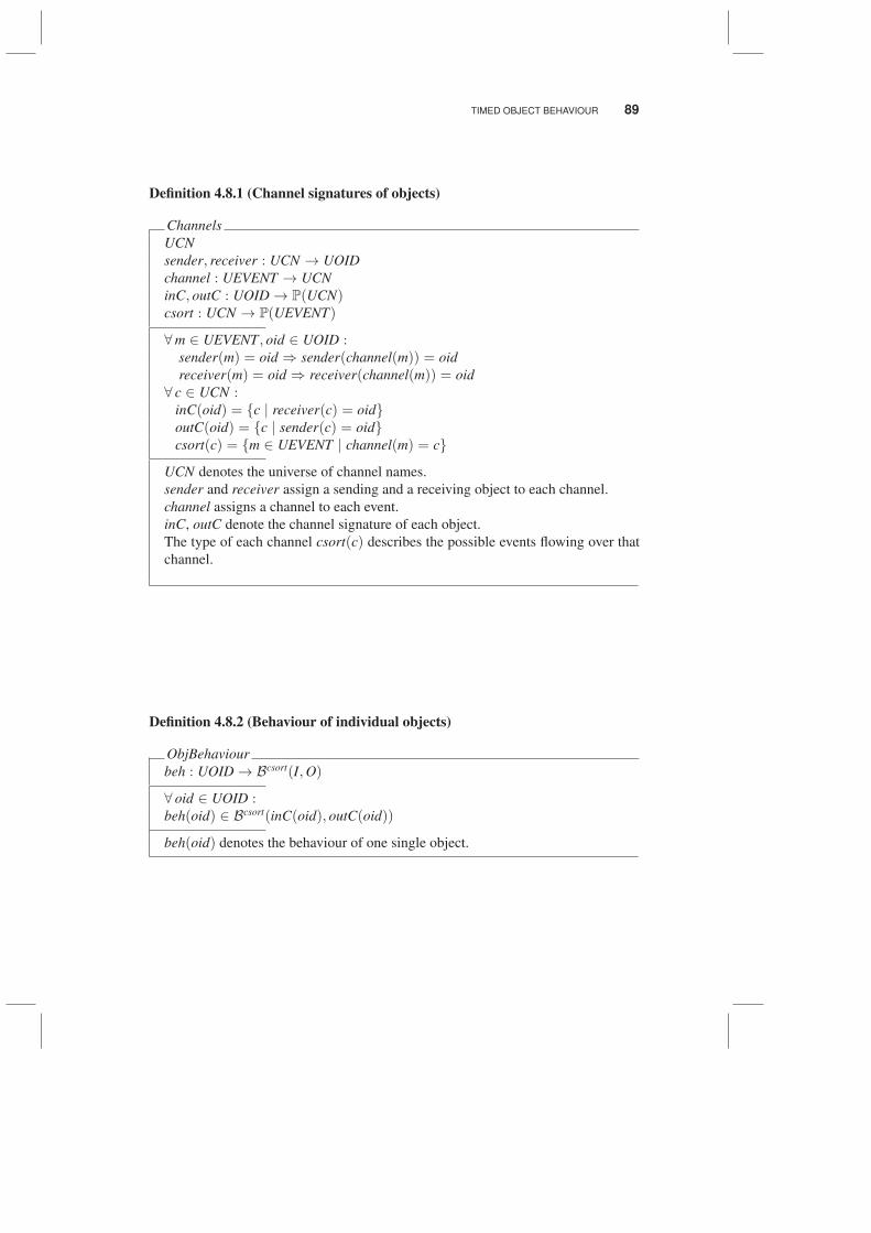
Definition 4.8.1 (Channel signatures of objects)
Channels
UCN
sender, receiver : UCN → UOID
channel : UEVENT → UCN
inC, outC : UOID → P(UCN)csort : UCN → P(UEVENT)
∀m ∈ UEVENT, oid ∈ UOID :sender(m) = oid ⇒ sender(channel(m)) = oid
receiver(m) = oid ⇒ receiver(channel(m)) = oid
∀ c ∈ UCN :inC(oid) = {c | receiver(c) = oid}outC(oid) = {c | sender(c) = oid}csort(c) = {m ∈ UEVENT | channel(m) = c}
UCN denotes the universe of channel names.
sender and receiver assign a sending and a receiving object to each channel.
channel assigns a channel to each event.
inC, outC denote the channel signature of each object.
The type of each channel csort(c) describes the possible events flowing over that
channel.
Definition 4.8.2 (Behaviour of individual objects)
ObjBehaviour
beh : UOID → Bcsort(I,O)
∀ oid ∈ UOID :beh(oid) ∈ Bcsort(inC(oid), outC(oid))
beh(oid) denotes the behaviour of one single object.
90 DEFINITION OF THE SYSTEM MODEL
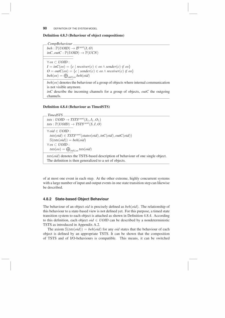
Definition 4.8.3 (Behaviour of object compositions)
CompBehaviour
beh : P(UOID)→ Bcsort(I,O)inC, outC : P(UOID)→ P(UCN)
∀ os ⊂ UOID :I = inC(os) = {c | receiver(c) ∈ os ∧ sender(c) 6∈ os}O = outC(os) = {c | sender(c) ∈ os ∧ receiver(c) 6∈ os}beh(os) =
⊕oid∈os beh(oid)
beh(os) denotes the behaviour of a group of objects where internal communication
is not visible anymore.
inC describe the incoming channels for a group of objects, outC the outgoing
channels.
Definition 4.8.4 (Behaviour as TimedSTS)
TimedSTS
tsts : UOID → TSTScsort(S1, I1,O1)tsts : P(UOID)→ TSTScsort(S, I,O)
∀ oid ∈ UOID :tsts(oid) ∈ TSTScsort(states(oid), inC(oid), outC(oid))S(tsts(oid)) = beh(oid)∀ os ⊂ UOID :
tsts(os) =⊕
oid∈os tsts(oid)
tsts(oid) denotes the TSTS-based description of behaviour of one single object.
The definition is then generalized to a set of objects.
of at most one event in each step. At the other extreme, highly concurrent systems
with a large number of input and output events in one state transition step can likewise
be described.
4.8.2 State-based Object Behaviour
The behaviour of an object oid is precisely defined as beh(oid). The relationship of
this behaviour to a state-based view is not defined yet. For this purpose, a timed state
transition system to each object is attached as shown in Definition 4.8.4. According
to this definition, each object oid ∈ UOID can be described by a nondeterministic
TSTS as introduced in Appendix A.2.
The axiom S(tsts(oid)) = beh(oid) for any oid states that the behaviour of each
object is defined by an appropriate TSTS. It can be shown that the composition
of TSTS and of I/O-behaviours is compatible. This means, it can be switched
THE SYSTEM MODEL DEFINITION 91
between a state-based and a purely I/O-based view of object behaviour, and moreover
the behaviour of objects or groups (components) can be individually specified and
afterwards meaningfully composed.
Note that each object oid has exactly one single TSTS tsts(oid). However, as
tsts(oid) is a nondeterministic state machine, it allows various forms of underspec-
ification. Therefore, there is no need to add a further concept of underspecification
by, e.g., assigning a set of possible TSTS to each object. Any UML model, however,
may have an impact on the elements of a TSTS. For instance, the sets of reachable
states can be constrained, the initial states restricted to be a singleton, or the non-
determinism reduced by enforcing a behaviour that is deterministic in reaction and
time.
With this last part of the system model, a TSTS for the whole system is available
that includes all snapshots and all system states and is thus capable of describing any
behavioural and structural restrictions by tsts(UOID). The overall system tsts(UOID)does not have any external channels, it incorporates all “objects”. This also includes
objects that have direct connections to interfaces to other systems, mechanical devices
or users and thus can act as surrogates for the context of the system. In other words,
the overall system makes a closed worlds assumption. In [9] includes a discussion
on how to deal with a closed world assumption to describe open, reactive systems,
and also what the advantages are implied by this assumption. In [1], also a general
mapping from event-based to TSTS is defined.
4.9 THE SYSTEM MODEL DEFINITION
The last Definition 4.9.1 finally introduces the universe of system models.
REFERENCES
1. Manfred Broy, Marıa Victoria Cengarle, Hans Gronniger, and Bernhard Rumpe. Modular
Description of a Comprehensive Semantics Model for the UML (Version 2.0). Technical
Report 2008-06, Carl-Friedrich-Gauß-Fakultat, Technische Universitat Braunschweig,
2008.
2. Manfred Broy, Frank Dederich, Claus Dendorfer, Max Fuchs, Thomas Gritzner, and
Rainer Weber. The Design of Distributed Systems - An Introduction to FOCUS. Technical
report, TUM-I9202, SFB-Bericht Nr. 342/2-2/92 A, 1993.
3. Marcus Fontoura, Wolfgang Pree, and Bernhard Rumpe. The UML/F Profile for Frame-
work Architecture. Addison-Wesley, 2001.
4. Erich Gamma, Richard Helm, Ralph Johnson, and John Vlissides. Design patterns:
elements of reusable object-oriented software. Addison-Wesley Professional, 1995.
5. Randy H. Katz. Contemporary logic design. Benjamin-Cummings Publishing Co., Inc.,
Redwood City, CA, USA, 1993.
6. N.A. Lynch and M.R. Tuttle. An Introduction to Input/Output Automata. CWI Quarterly,
2:219 – 246, 1989.
92 DEFINITION OF THE SYSTEM MODEL
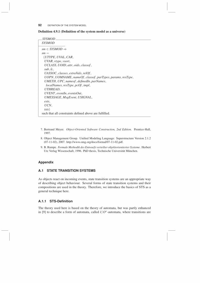
Definition 4.9.1 (Definition of the system model as a universe)
SYSMOD
SYSMOD
sm ∈ SYSMOD ⇒sm =(UTYPE,UVAL,CAR,UVAR, vtype, vsort,UCLASS,UOID, attr, oids, classof ,sub,&,UASSOC, classes, extraVals, relOf ,UOPN,UOMNAME, nameOf , classof , parTypes, params, resType,UMETH,UPC, nameof , definedIn, parNames,
localNames, resType, pcOf , impl,UTHREAD,UVENT, eventIn, eventsOut,UMESSAGE,MsgEvent,USIGNAL,ests,UCN,tsts)
such that all constraints defined above are fulfilled.
7. Bertrand Meyer. Object-Oriented Software Construction, 2nd Edition. Prentice-Hall,
1997.
8. Object Management Group. Unified Modeling Language: Superstructure Version 2.1.2
(07-11-02), 2007. http://www.omg.org/docs/formal/07-11-02.pdf.
9. B. Rumpe. Formale Methodik des Entwurfs verteilter objektorientierter Systeme. Herbert
Utz Verlag Wissenschaft, 1996. PhD thesis, Technische Universitat Munchen.
Appendix
A.1 STATE TRANSITION SYSTEMS
As objects react on incoming events, state transition systems are an appropriate way
of describing object behaviour. Several forms of state transition systems and their
compositions are used in the theory. Therefore, we introduce the basics of STS as a
general technique here.
A.1.1 STS-Definition
The theory used here is based on the theory of automata, but was partly enhanced
in [9] to describe a form of automata, called I/O∗-automata, where transitions are
TIMED STATE TRANSITION SYSTEMS 93
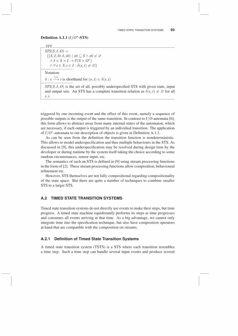
Definition A.1.1 (I/O∗-STS)
STS
STS(S, I,O) ={(S, I,O, δ, s0) | s0 ⊆ S ∧ s0 6= ∅
∧ δ ∈ S× I → P(S× O∗)∧ ∀ s ∈ S, i ∈ I : δ(s, i) 6= ∅}
Notation:
δ : si/o−→ t is shorthand for (o, t) ∈ δ(s, i)
STS(S, I,O) is the set of all, possibly underspecified STS with given state, input
and output sets. An STS has a complete transition relation as δ(s, i) 6= ∅ for all
s, i.
triggered by one incoming event and the effect of this event, namely a sequence of
possible outputs is the output of the same transition. In contrast to I/O-automata [6],
this form allows to abstract away from many internal states of the automaton, which
are necessary, if each output is triggered by an individual transition. The application
of I/O∗-automata to our description of objects is given in Definition A.1.1.
As can be seen from the definition the transition function is nondeterministic.
This allows to model underspecification and thus multiple behaviours in the STS. As
discussed in [9], this underspecification may be resolved during design time by the
developer or during runtime by the system itself taking the choice according to some
random circumstances, sensor input, etc.
The semantics of such an STS is defined in [9] using stream processing functions
in the form of [2]. These stream processing functions allow composition, behavioural
refinement etc.
However, STS themselves are not fully compositional regarding compositionality
of the state space. But there are quite a number of techniques to combine smaller
STS to a larger STS.
A.2 TIMED STATE TRANSITION SYSTEMS
Timed state transition systems do not directly use events to make their steps, but time
progress. A timed state machine equidistantly performs its steps as time progresses
and consumes all events arriving at that time. As a big advantage, we cannot only
integrate time into the specification technique, but also have composition operators
at hand that are compatible with the composition on streams.
A.2.1 Definition of Timed State Transition Systems
A timed state transition system (TSTS) is a STS where each transition resembles
a time step. Such a time step can handle several input events and produce several
Recommended