POWERMASTER
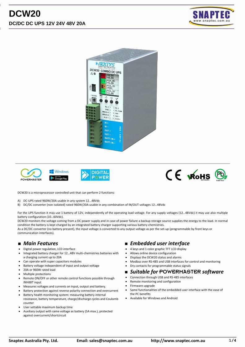
DCW20 is a microprocessor controlled unit that can perform 2 functions: A) DC-UPS rated 960W/20A usable in any system 12…48Vdc B) DC/DC converter (non isolated) rated 960W/20A usable in any combination of IN/OUT voltages 12…48Vdc For the UPS function it may use 1 battery of 12V, independently of the operating load voltage. For any supply voltages (12…48Vdc) it may use also multiple battery configuration (10…60Vdc). DCW20 monitors the voltage coming from a DC power supply and in case of power failure a backup storage source supplies the energy to the load. In normal condition the battery is kept charged by an integrated battery charger supporting various battery chemistries. As a DC/DC converter (no battery present), the input voltage is converted to any output voltage as per the set-up (programmable by front keys or communication interfaces).
▪ Main Features • Digital power regulation, LCD interface
• Integrated battery charger for 12…48V multi-chemistries batteries with a charging current up to 20A
• Can operate with super capacitors modules
• Battery voltage independent of input and output voltage
• 20A or 960W rated load
• Multiple protections
• Remote ON/OFF or other remote control functions possible through INHIBIT input
• Measures voltages and currents on input, output and battery.
• Battery protection against reverse polarity connection and overcurrent
• Battery health monitoring system: measuring battery internal resistance, battery temperature, charge/discharge cycles and Coulomb counter
• User settable maximum backup time
• Auxiliary output with same voltage as battery (5A max.), protected against overcurrent/shortcircuit
▪ Embedded user interface • 4 keys and 1 color graphic TFT LCD display
• Allows online device configuration
• Displays the DCW20 status and alarms
• Modbus over RS-485 and USB interfaces for control and monitoring
• Dry contacts for programmable status signals
▪ Suitable for POWERMASTER software • Connection through USB and RS-485 interfaces
• Remote monitoring and configuration
• Firmware upgrade
• Same functionalities of the embedded user interface with the ease of the PC benefits
• Available for Windows and Android
1/4Snaptec Australia Pty. Ltd. Email: [email protected] http://www.snaptec.com.au
DCW20DC/DC DC UPS 12V 24V 48V 20A
TECHNICAL DATA
Model type DCW20
INPUT DATA
Input DC voltage Nominal: 12…48Vdc
Range: 10…60Vdc
Input DC current 20A
Standby power < 4W
MAIN OUTPUT SECTION
Voltage Nominal: 12…48Vdc
(= Vin for use as UPS; according to set-up for use as DC/DC converter)
Maximum Current / Power 20A / 960W
Load regulation ± 1%
AUXILIARY OUTPUT SECTION
Voltage Nominal: 12…48Vdc
(= U battery - non regulated)
Continuous current 5A
Overload limit 6A
BATTERY SECTION
Battery voltage (or to be used as input for DC/DC conversion)
Nominal: 12…48Vdc Range: 10…60Vdc
Battery chemistries
▪ Lead Acid ▪ Nickel ▪ Lithium ▪ Supercap capacitors
Maximum battery charge current 20A
Maximum battery discharge current 20A
Allowed battery capacity up to 400Ah
Battery protections ▪ Overcurrent ▪ Deep discharge ▪ Reverse polarity
BATTERY HEALTH MONITORING
Battery internal resistance range 1mΩ…300mΩ
Additional monitoring functions
▪ Coulomb counter ▪ Battery temperature through 10kΩ NTC sensor (optional WNTC-2MT) ▪ Battery operating time since installation ▪ Number of cycles
USER INTERFACE
1.5 inch color graphic LCD Used to display the unit’s status and to access the configuration menus
4 keys Used to program the unit and to access various menus
Red LED ▪ Constantly ON: generic failure on the system, details on the LCD ▪ Blinking: battery backup function active
2 dry contact relays (NO, 30Vdc / 1A)
▪ RL1 / RL2 - Configurable ▪ RL COM - Common Pin
Other interfaces ▪ INH - (INHIBIT) Isolated remote ON/OFF input, active for 5…30Vdc ▪ T SENSE - optional, remote temperature sensor for battery charging (WNTC-2MT) ▪ Modbus over USB and RS-485 interfaces
GENERAL DATA
Efficiency at full load Power loss (in UPS mode with Vin present)
> 98% < 7W
Efficiency at full load Power loss (in UPS mode during backup)
> 97% < 15W
Efficiency at full load Power loss (DC-DC mode)
> 97% < 15W
Battery charge efficiency Power loss
> 96% < 20W
Maximum backup time User programmable, up to battery deep discharge threshold
Operating temperature¹ -40°C…+80°C
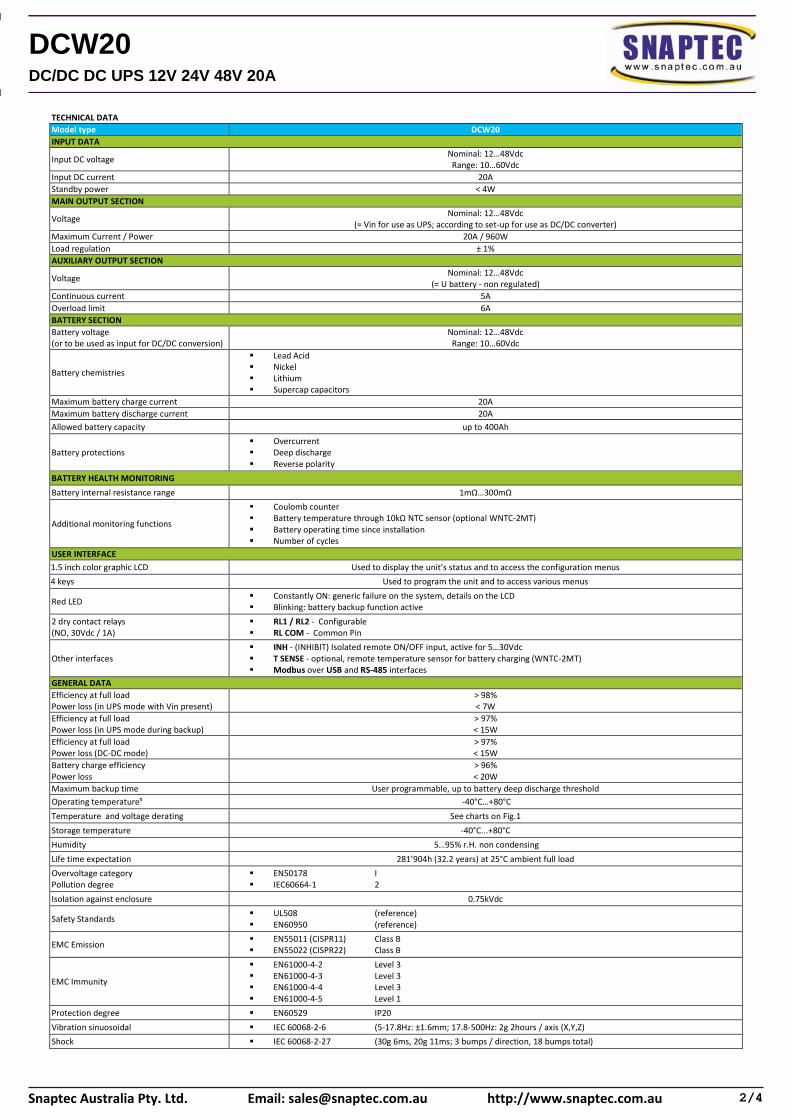
Temperature and voltage derating See charts on Fig.1
Storage temperature -40°C...+80°C
Humidity 5…95% r.H. non condensing
Life time expectation 281’904h (32.2 years) at 25°C ambient full load
Overvoltage category Pollution degree
▪ EN50178 I ▪ IEC60664-1 2
Isolation against enclosure 0.75kVdc
Safety Standards ▪ UL508 (reference) ▪ EN60950 (reference)
EMC Emission ▪ EN55011 (CISPR11) Class B ▪ EN55022 (CISPR22) Class B
EMC Immunity
▪ EN61000-4-2 Level 3 ▪ EN61000-4-3 Level 3 ▪ EN61000-4-4 Level 3 ▪ EN61000-4-5 Level 1
Protection degree ▪ EN60529 IP20
Vibration sinuosoidal ▪ IEC 60068-2-6 (5-17.8Hz: ±1.6mm; 17.8-500Hz: 2g 2hours / axis (X,Y,Z)
Shock ▪ IEC 60068-2-27 (30g 6ms, 20g 11ms; 3 bumps / direction, 18 bumps total)
2/4Snaptec Australia Pty. Ltd. Email: [email protected] http://www.snaptec.com.au
DCW20DC/DC DC UPS 12V 24V 48V 20A
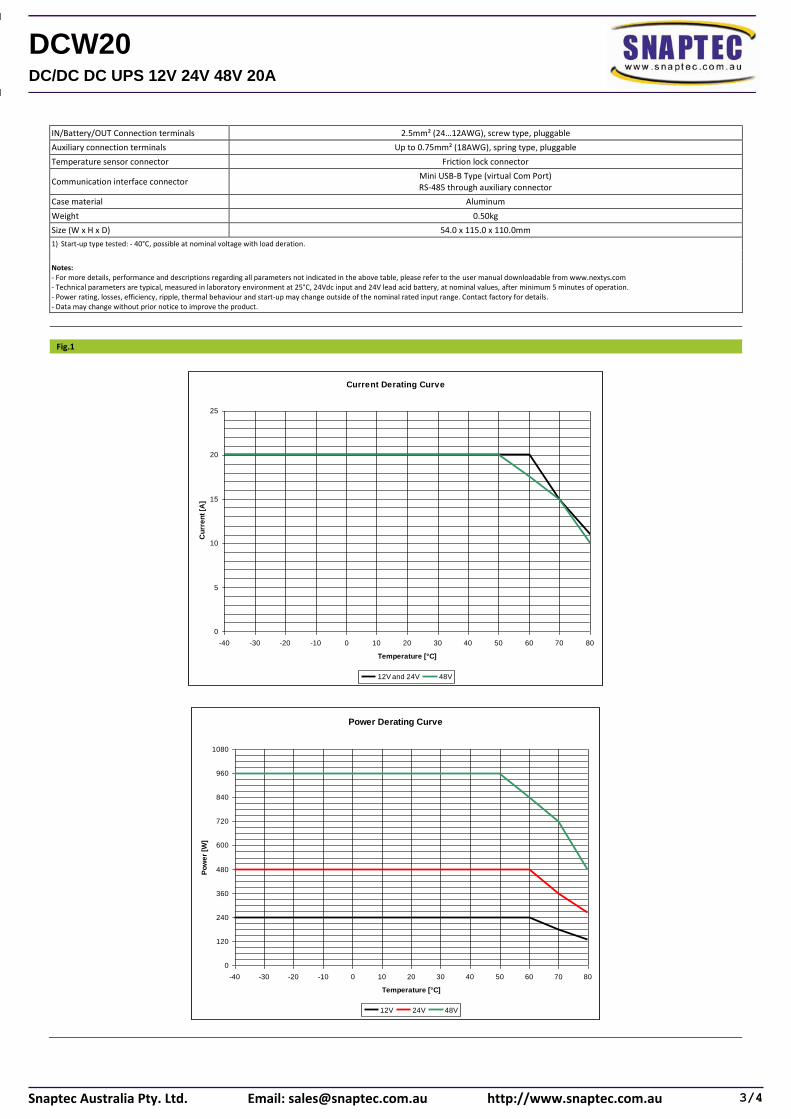
IN/Battery/OUT Connection terminals 2.5mm² (24…12AWG), screw type, pluggable
Auxiliary connection terminals Up to 0.75mm² (18AWG), spring type, pluggable
Temperature sensor connector Friction lock connector
Communication interface connector Mini USB-B Type (virtual Com Port) RS-485 through auxiliary connector
Case material Aluminum
Weight 0.50kg
Size (W x H x D) 54.0 x 115.0 x 110.0mm
1) Start-up type tested: - 40°C, possible at nominal voltage with load deration.
Notes: - For more details, performance and descriptions regarding all parameters not indicated in the above table, please refer to the user manual downloadable from www.nextys.com - Technical parameters are typical, measured in laboratory environment at 25°C, 24Vdc input and 24V lead acid battery, at nominal values, after minimum 5 minutes of operation. - Power rating, losses, efficiency, ripple, thermal behaviour and start-up may change outside of the nominal rated input range. Contact factory for details. - Data may change without prior notice to improve the product.
Fig.1
Current Derating Curve
0
5
10
15
20
25
-40 -30 -20 -10 0 10 20 30 40 50 60 70 80
Temperature [°C]
Cu
rre
nt
[A]
12V and 24V 48V
Power Derating Curve
0
120
240
360
480
600
720
840
960
1080
-40 -30 -20 -10 0 10 20 30 40 50 60 70 80
Temperature [°C]
Po
we
r [W
]
12V 24V 48V
3/4Snaptec Australia Pty. Ltd. Email: [email protected] http://www.snaptec.com.au
DCW20DC/DC DC UPS 12V 24V 48V 20A
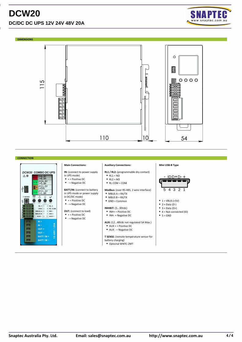
DIMENSIONS
CONNECTION
Main Connections: IN: (connect to power supply in UPS mode)
▪ + = Positive DC
▪ - = Negative DC BATT/IN: (connect to battery in UPS mode or power supply in DC/DC mode)
▪ + = Positive DC
▪ - = Negative DC OUT: (connect to load)
▪ + = Positive DC
▪ - = Negative DC
Auxiliary Connections: RL1 / RL2: (programmable dry contact)
▪ RL1 = NO
▪ RL2 = NO
▪ RL COM = COM Modbus: (over RS-485, 2 wire interface)
▪ MBUS A = RX/TX
▪ MBUS B = RX/TX
▪ GND = Common INHIBIT: (5…30Vdc)
▪ INH+ = Positive DC
▪ INH- = Negative DC AUX: (12…48Vdc not regulated 5A Max.)
▪ AUX + = Positive DC
▪ AUX - = Negative DC T SENSE: (remote temperature sensor for battery charging)
▪ Optional WNTC-2MT
Mini USB-B Type
▪ 1 = VBUS (+5V)
▪ 2 = Data (D-)
▪ 3 = Data (D+)
▪ 4 = Not connected (ID)
▪ 5 = GND
4/4Snaptec Australia Pty. Ltd. Email: [email protected] http://www.snaptec.com.au
DCW20DC/DC DC UPS 12V 24V 48V 20A
Recommended