KL3073
DC Machines
Direct Current (DC) Machines Fundamentals
Generator action: An emf (voltage) is induced in a conductor if it moves through a magnetic field.
Motor action: A force is induced in a conductor that has a current going through it and placed in a magnetic field.
Any DC machine can act either as a generator or as a motor.
Simplest rotating dc machine
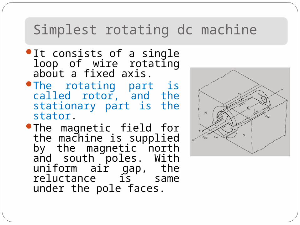
It consists of a single loop of wire rotating about a fixed axis.
The rotating part is called rotor, and the stationary part is the stator.
The magnetic field for the machine is supplied by the magnetic north and south poles. With uniform air gap, the reluctance is same under the pole faces.
The Voltage Induced in a Rotating Loop
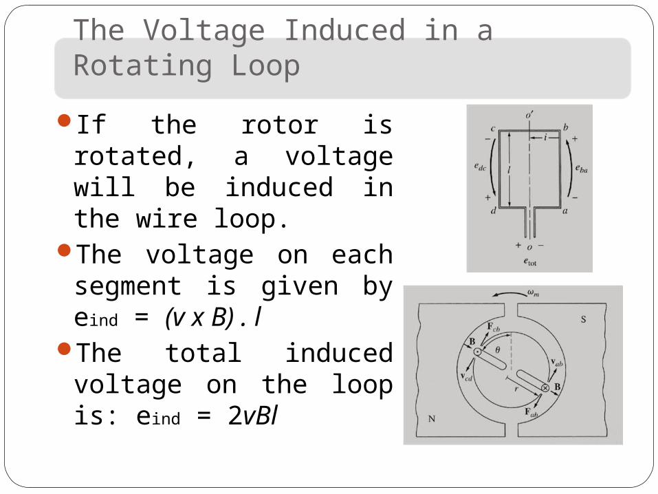
If the rotor is rotated, a voltage will be induced in the wire loop.
The voltage on each segment is given by eind = (v x B) . l
The total induced voltage on the loop is: eind = 2vBl
The Voltage Induced in a Rotating Loop
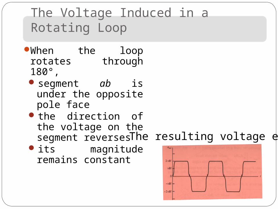
When the loop rotates through 180°, segment ab is
under the opposite pole face
the direction of the voltage on the segment reverses
its magnitude remains constant
The resulting voltage etot
The Voltage Induced in a Rotating Loop
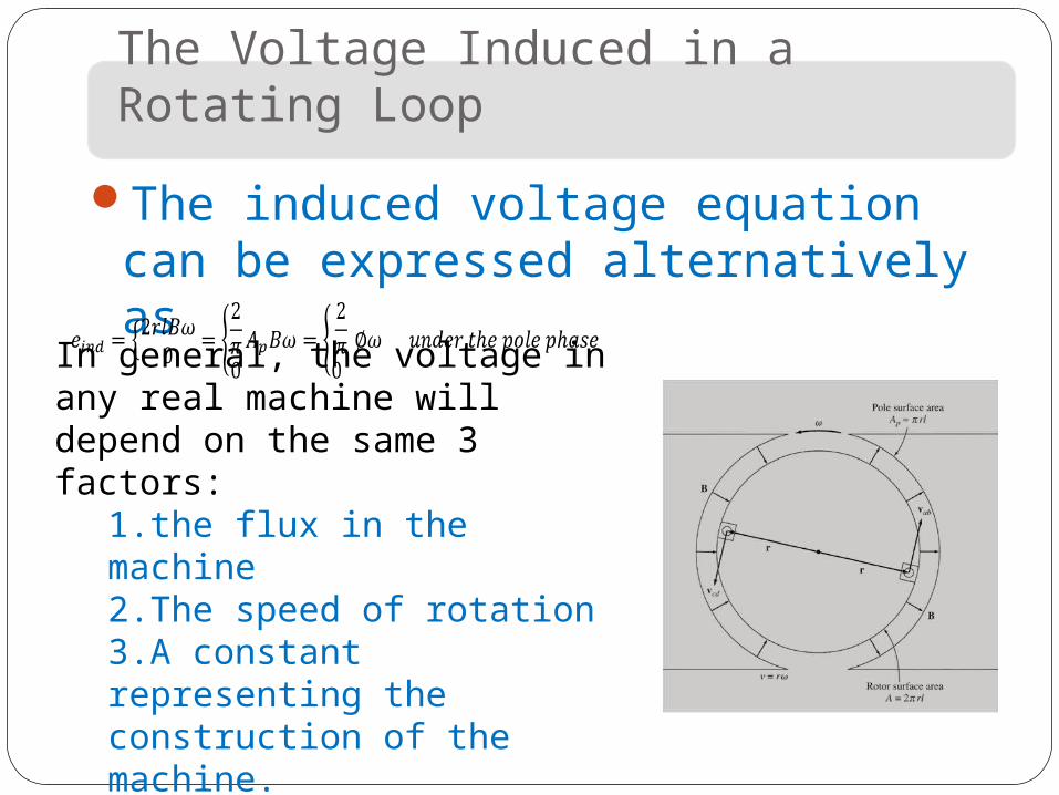
The induced voltage equation can be expressed alternatively as
In general, the voltage in any real machine will depend on the same 3 factors:
1.the flux in the machine2.The speed of rotation3.A constant representing the construction of the machine.
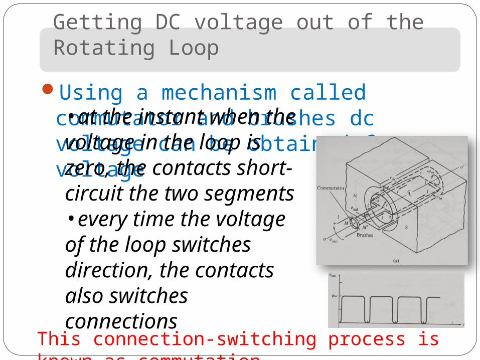
Getting DC voltage out of the Rotating Loop
Using a mechanism called commutator and brushes dc voltage can be obtained from ac voltage
•at the instant when the voltage in the loop is zero, the contacts short-circuit the two segments•every time the voltage of the loop switches direction, the contacts also switches connectionsThis connection-switching process is known
as commutation
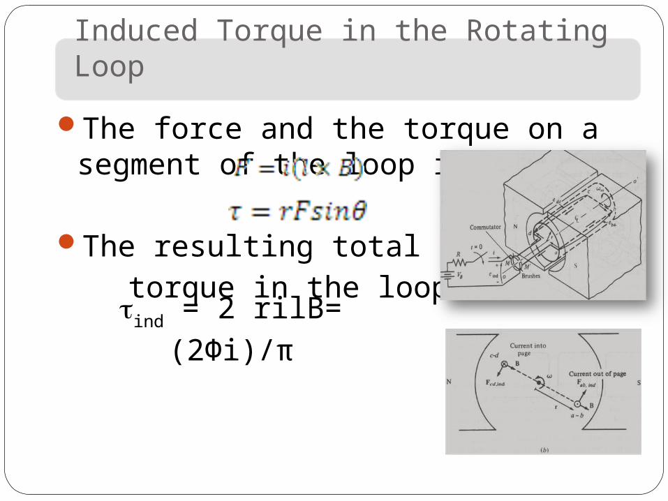
Induced Torque in the Rotating Loop
The force and the torque on a segment of the loop is given by
The resulting total induced torque in the loop is
ind = 2 rilB= (2Фi)/π
Induced Torque in the Rotating Loop
In general, the torque in any real machine will depend on the same 3 factors:
1. The flux in the machine2. The current in the machine3. A constant representing the
construction of the machine.

DC Machine ConstructionThe stator of the dc
machine has poles, which are excited by either dc current or permanent magnets to produce magnetic fields.
In the neutral zone, in the middle between the poles, commutating poles are placed to reduce sparking of the commutator.
Compensating windings are mounted on the main poles. These reduces flux weakening commutation problems.
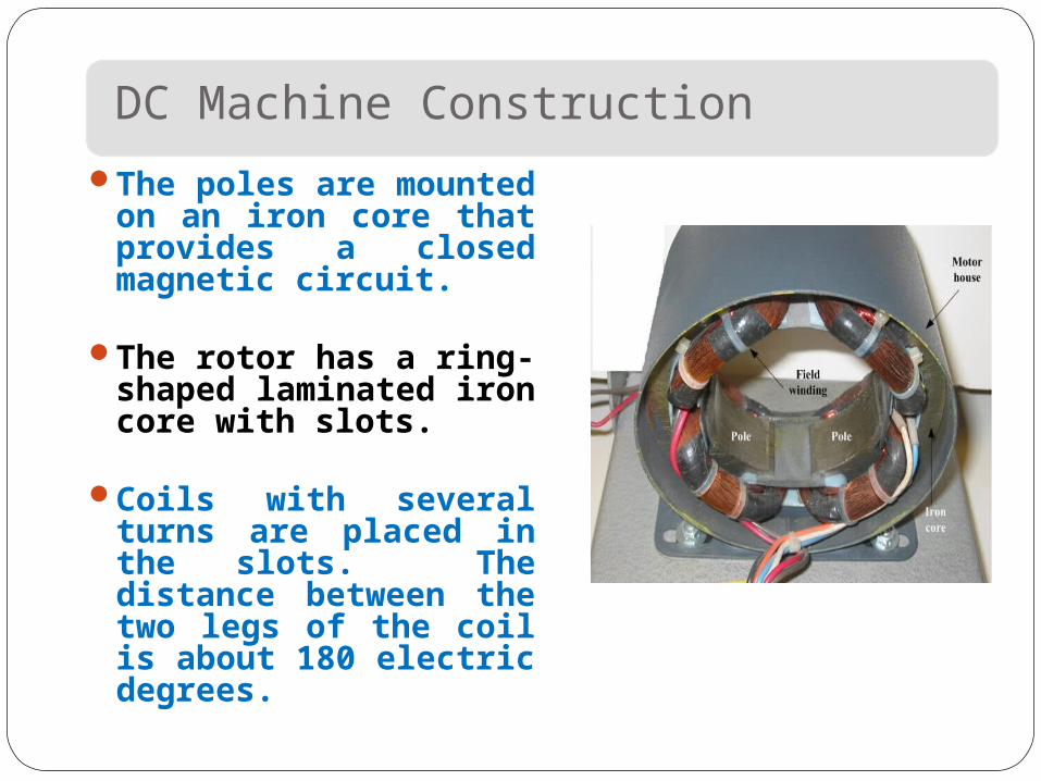
DC Machine Construction
The poles are mounted on an iron core that provides a closed magnetic circuit.
The rotor has a ring-shaped laminated iron core with slots.
Coils with several turns are placed in the slots. The distance between the two legs of the coil is about 180 electric degrees.
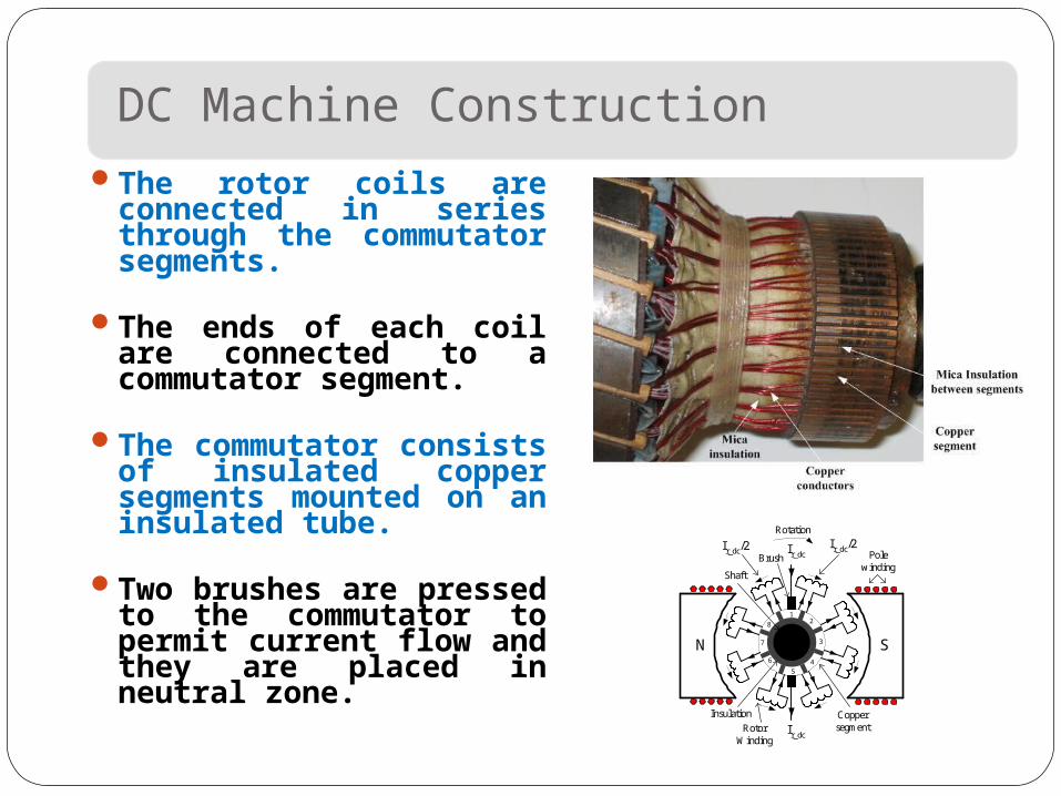
DC Machine ConstructionThe rotor coils are
connected in series through the commutator segments.
The ends of each coil are connected to a commutator segment.
The commutator consists of insulated copper segments mounted on an insulated tube.
Two brushes are pressed to the commutator to permit current flow and they are placed in neutral zone.
|
Shaft
Brush
Coppersegment
Insulation
RotorWinding
N S
Ir_dcIr_dc/2
Rotation
Ir_dc/2
Ir_dc
12
3
4
5
6
7
8
Polewinding
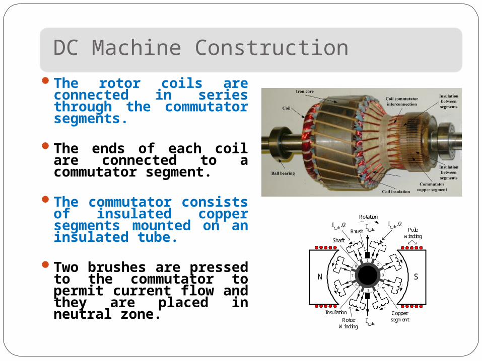
Commutation Process
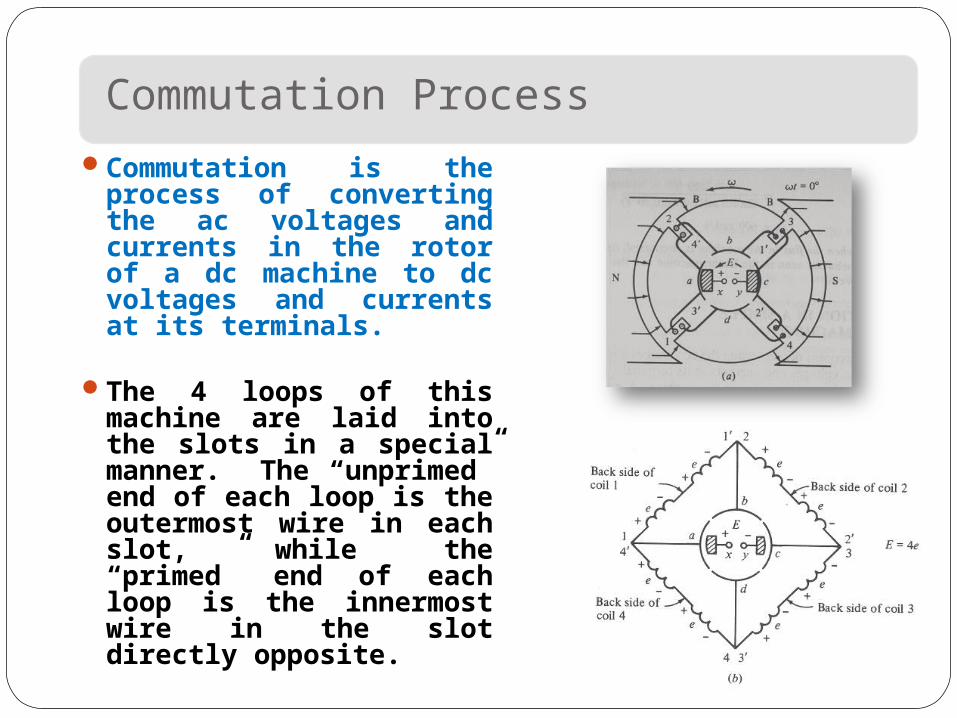
Commutation is the process of converting the ac voltages and currents in the rotor of a dc machine to dc voltages and currents at its terminals.
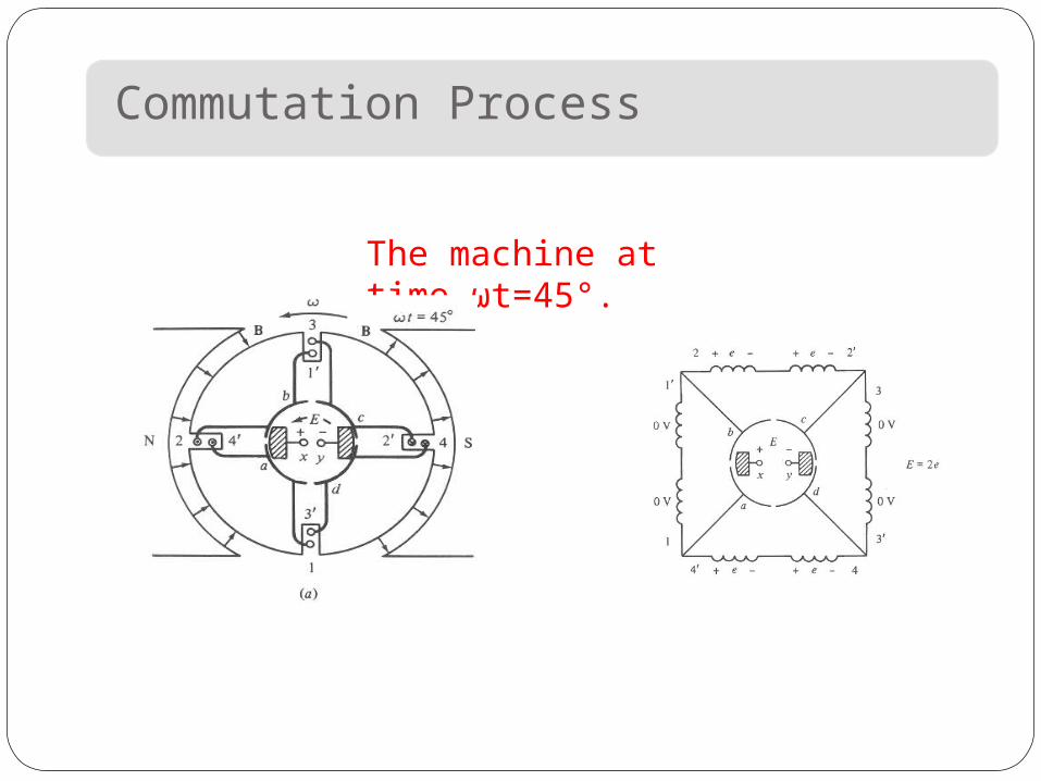
The 4 loops of this machine are laid into the slots in a special manner. The “unprimed” end of each loop is the outermost wire in each slot, while the “primed” end of each loop is the innermost wire in the slot directly opposite.
Commutation Process
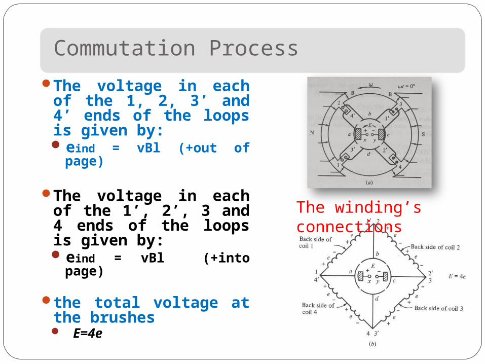
The voltage in each of the 1, 2, 3’ and 4’ ends of the loops is given by:eind = vBl (+out of
page)
The voltage in each of the 1’, 2’, 3 and 4 ends of the loops is given by:eind = vBl (+into
page)
the total voltage at the brushes E=4e
The winding’s connections
Commutation Process
The machine at time ωt=45°.
Commutation Process
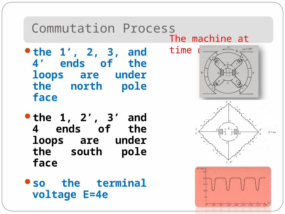
the 1’, 2, 3, and 4’ ends of the loops are under the north pole face
the 1, 2’, 3’ and 4 ends of the loops are under the south pole face
so the terminal voltage E=4e
The machine at time ωt=90°.
Problems with Commutation in Real Machines
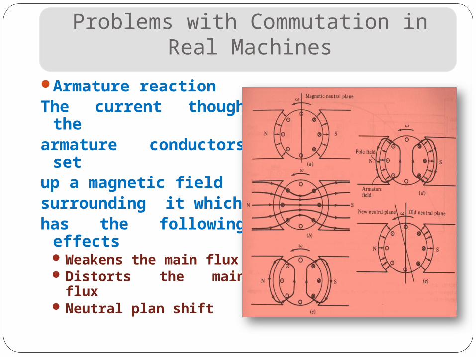
Armature reactionThe current though
thearmature
conductors setup a magnetic fieldsurrounding it whichhas the following
effectsWeakens the main
fluxDistorts the main fluxNeutral plan shift
Problems with Commutation in Real Machines
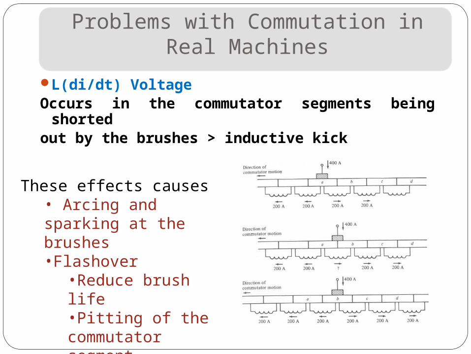
L(di/dt) VoltageOccurs in the commutator segments being
shortedout by the brushes > inductive kick
These effects causes• Arcing and sparking at the brushes•Flashover
•Reduce brush life•Pitting of the commutator segment
Solutions to Problems with Commutation in Real Machines
Brush shiftingCommutating poles or interpolesCompensating windings
Solutions to Problems with Commutation in Real Machines
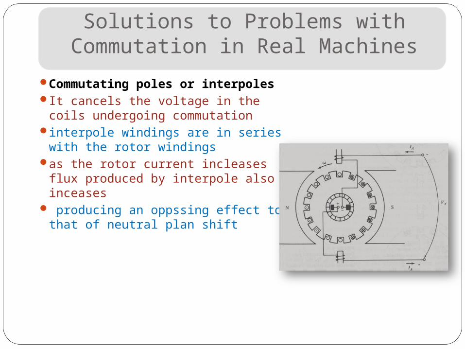
Commutating poles or interpoles
It cancels the voltage in the coils undergoing commutation
interpole windings are in series with the rotor windings
as the rotor current incleases flux produced by interpole also inceases
producing an oppssing effect to that of neutral plan shift
Solutions to Problems with Commutation in Real Machines
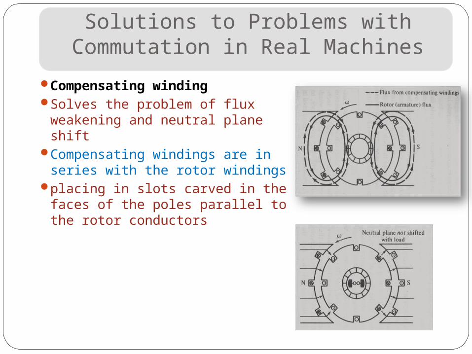
Compensating windingSolves the problem of flux
weakening and neutral plane shift
Compensating windings are in series with the rotor windings
placing in slots carved in the faces of the poles parallel to the rotor conductors
The Internal Generated Voltage Equations Of Real Machines
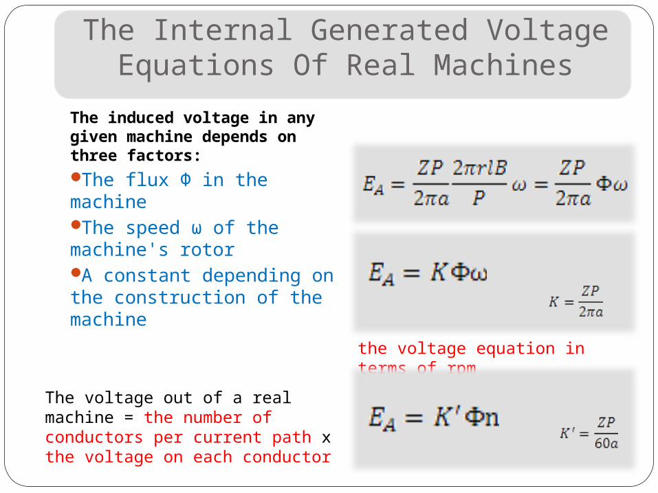
The induced voltage in any given machine depends on three factors:The flux Φ in the machineThe speed ω of the machine's rotorA constant depending on the construction of the machine
The voltage out of a real machine = the number of conductors per current path x the voltage on each conductor
the voltage equation in terms of rpm
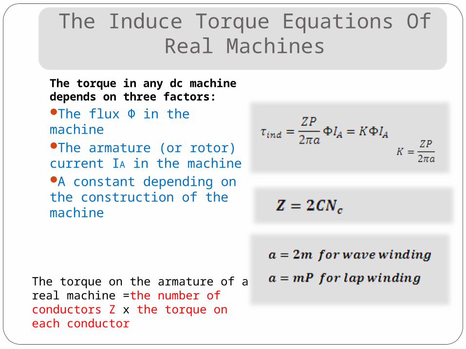
The Induce Torque Equations Of Real Machines
The torque in any dc machine depends on three factors:The flux Φ in the machineThe armature (or rotor) current IA in the machine A constant depending on the construction of the machine
The torque on the armature of a real machine =the number of conductors Z x the torque on each conductor
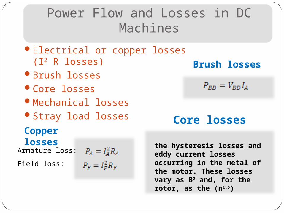
Power Flow and Losses in DC Machines
Electrical or copper losses (I2 R losses)
Brush lossesCore lossesMechanical lossesStray load losses
Armature loss:
Field loss:
Copper losses
Brush losses
Core losses
the hysteresis losses and eddy current losses occurring in the metal of the motor. These losses vary as B2 and, for the rotor, as the (n1.5)
Power Flow and Losses in DC Machines
Mechanical lossesFriction losses are losses caused by the friction of the bearings in the machineWindage losses are caused by the friction between the moving parts of the machine and the air inside the motor's casing
Stray losses Unknown lossesBy convention to be 1 percent of full load
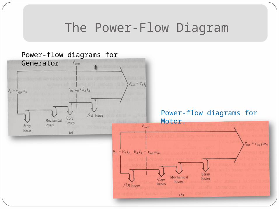
The Power-Flow Diagram
Power-flow diagrams for Generator
Power-flow diagrams for Motor.
DC GENERATORS
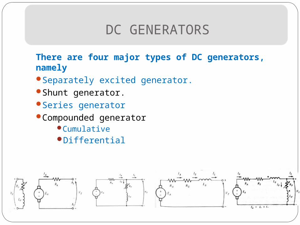
There are four major types of DC generators, namelySeparately excited generator.Shunt generator.Series generatorCompounded generator
Cumulative Differential
The Equivalent Circuit of a DC Generator
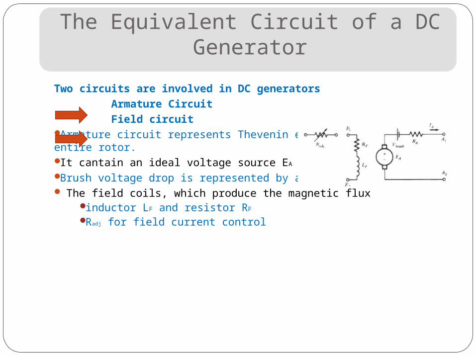
Two circuits are involved in DC generators
Armature Circuit
Field circuitArmature circuit represents Thevenin equivalent of the entire rotor.It cantain an ideal voltage source EA and a resistor RA. .Brush voltage drop is represented by a small battery The field coils, which produce the magnetic flux
inductor LF and resistor RF Radj for field current control
Magnetizing curve of a DC Generator & performance
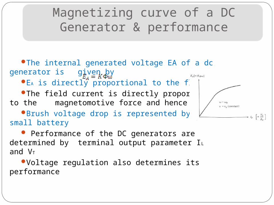
The internal generated voltage EA of a dc generator is given by
EA is directly proportional to the flux The field current is directly proportional to
the magnetomotive force and hence EA
Brush voltage drop is represented by a small battery
Performance of the DC generators are determined by terminal output parameter IL and VT
Voltage regulation also determines its performance
The Separately Excited Generator
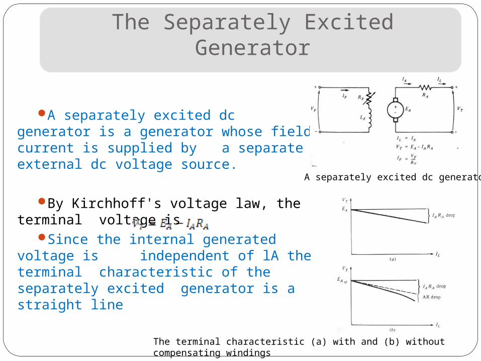
A separately excited dc generator is a generator whose field current is supplied by a separate external dc voltage source.
By Kirchhoff's voltage law, the terminal voltage is
Since the internal generated voltage is independent of lA the terminal characteristic of the separately excited generator is a straight line
A separately excited dc generator
The terminal characteristic (a) with and (b) without compensating windings
The Separately Excited Generator
Control of Terminal Voltage > two methods
Change the speed of rotationEA = KФω↑ >VT = EA ↑ - lARA >
VT ↑
Change the field current.IF = VF/RF↓ > IF ↑ > Ф ↑> EA =
KФ↑ω >VT = EA ↑ - lA RA > VT ↑
The terminal characteristic (a) with and (b) without compensating windings
The Separately Excited Generator
It is not possible to predict analytically the value of EA to be expected from a given field current. Magnetization curve of the generator must be used to calculte EA accurately.Net mmf is and IF equivalent is The magnetization curves for a generator are drawn for a particular speed, usually the rated speed of the machine.
If the machine is turning at other speeds than the EA in a machine is related to speed by
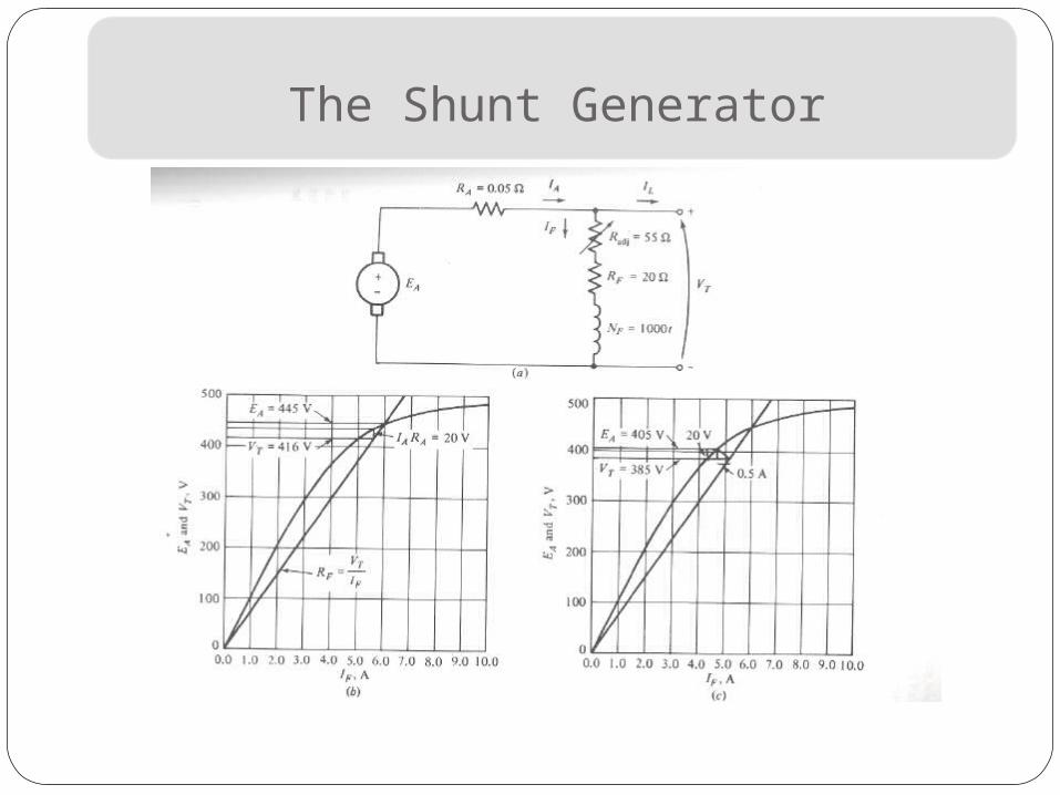
The Shunt Generator
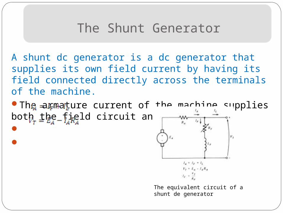
A shunt dc generator is a dc generator that supplies its own field current by having its field connected directly across the terminals of the machine. The armature current of the machine supplies both the field circuit and the load
The equivalent circuit of a shunt de generator
The Shunt Generator
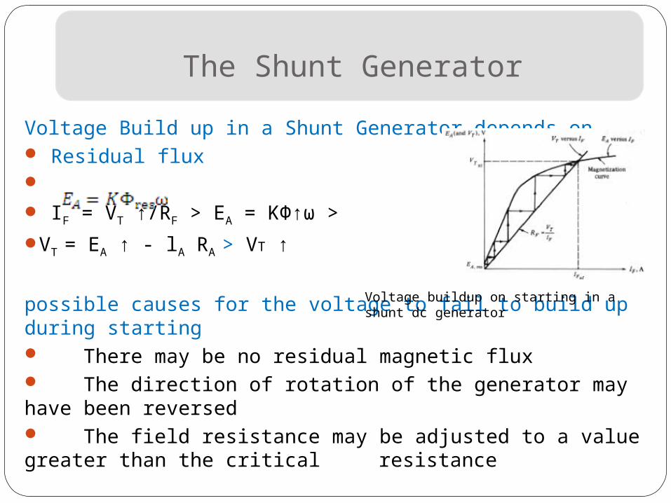
Voltage Build up in a Shunt Generator depends on Residual flux IF = VT ↑/RF > EA = KФ↑ω >
VT = EA ↑ - lA RA > VT ↑
possible causes for the voltage to fail to build up during starting There may be no residual magnetic flux The direction of rotation of the generator may have been reversed The field resistance may be adjusted to a value greater than the critical resistance
Voltage buildup on starting in a shunt dc generator
The Shunt Generator
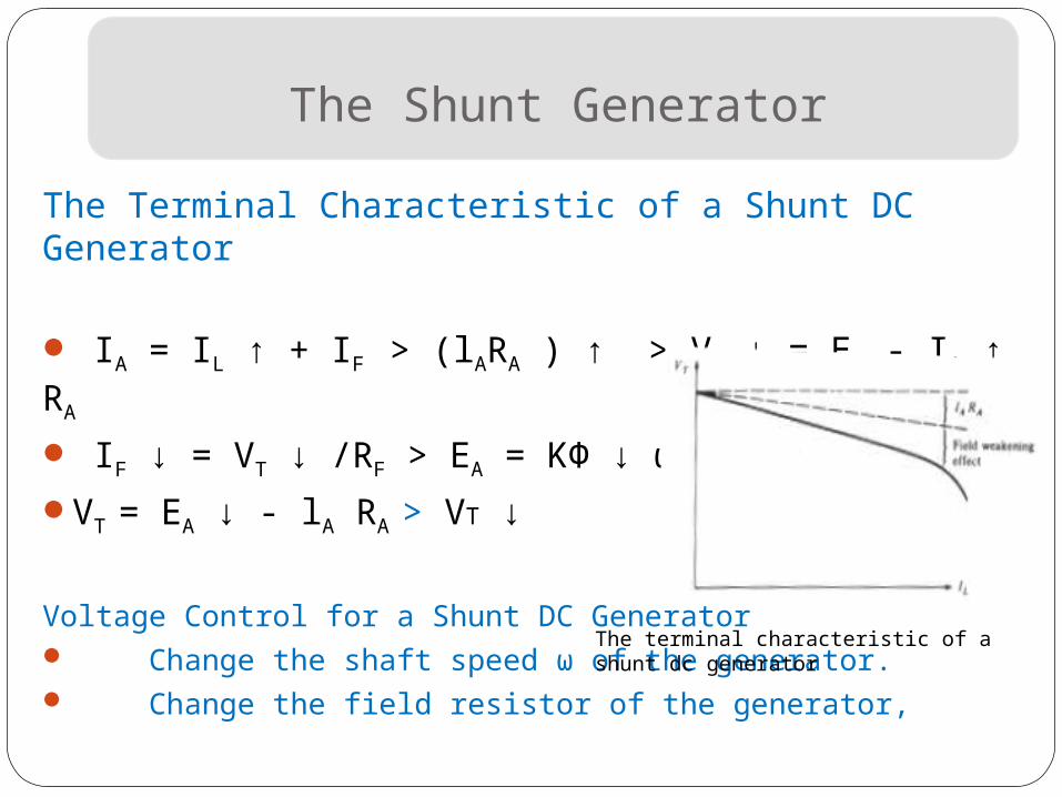
The Terminal Characteristic of a Shunt DC Generator IA = IL ↑ + IF > (lARA ) ↑ > VT ↓ = EA - IA ↑ RA
IF ↓ = VT ↓ /RF > EA = KФ ↓ ω >
VT = EA ↓ - lA RA > VT ↓
Voltage Control for a Shunt DC Generator Change the shaft speed ω of the generator. Change the field resistor of the generator,
The terminal characteristic of a shunt dc generator
The Shunt Generator
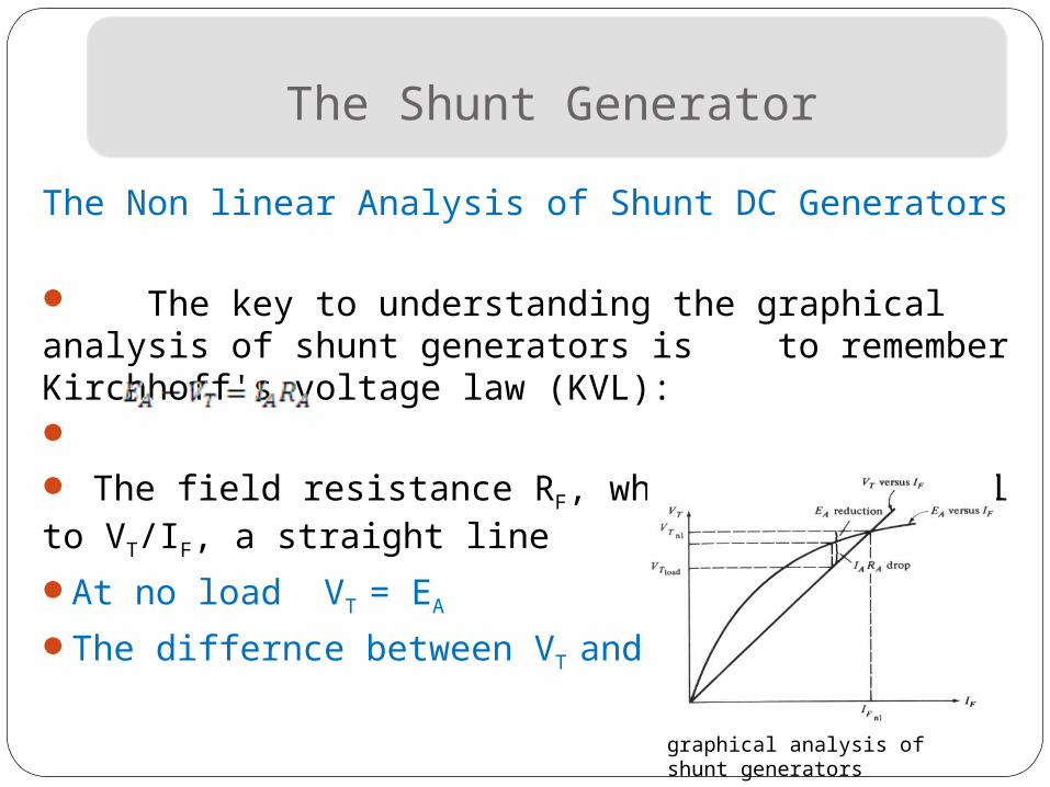
The Non linear Analysis of Shunt DC Generators The key to understanding the graphical analysis of shunt generators is to remember Kirchhoff's voltage law (KVL): The field resistance RF, which is just equal to VT/IF, a straight lineAt no load VT = EA
The differnce between VT and EA is lARA
graphical analysis of shunt generators
The Shunt Generator
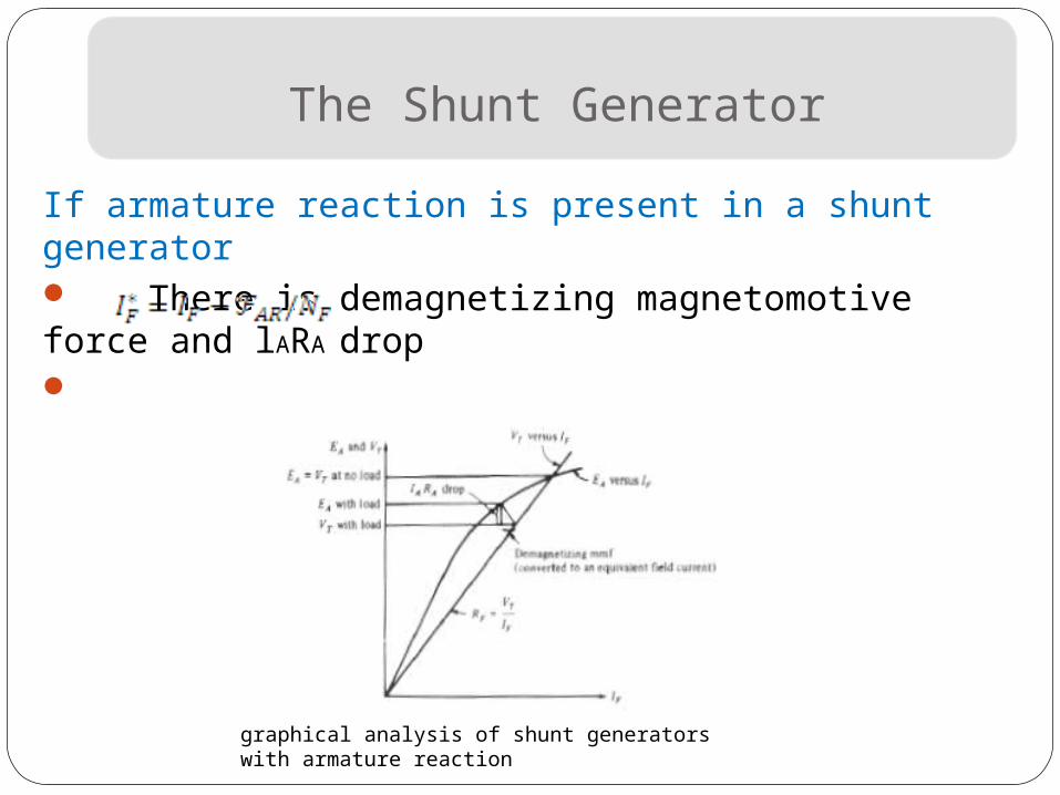
If armature reaction is present in a shunt generator There is demagnetizing magnetomotive force and lARA drop
graphical analysis of shunt generators with armature reaction
The Shunt Generator
The Shunt Generator
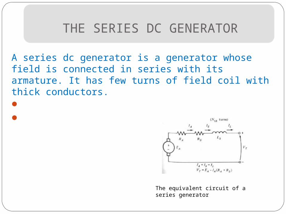
THE SERIES DC GENERATOR
A series dc generator is a generator whose field is connected in series with its armature. It has few turns of field coil with thick conductors.
The equivalent circuit of a series generator
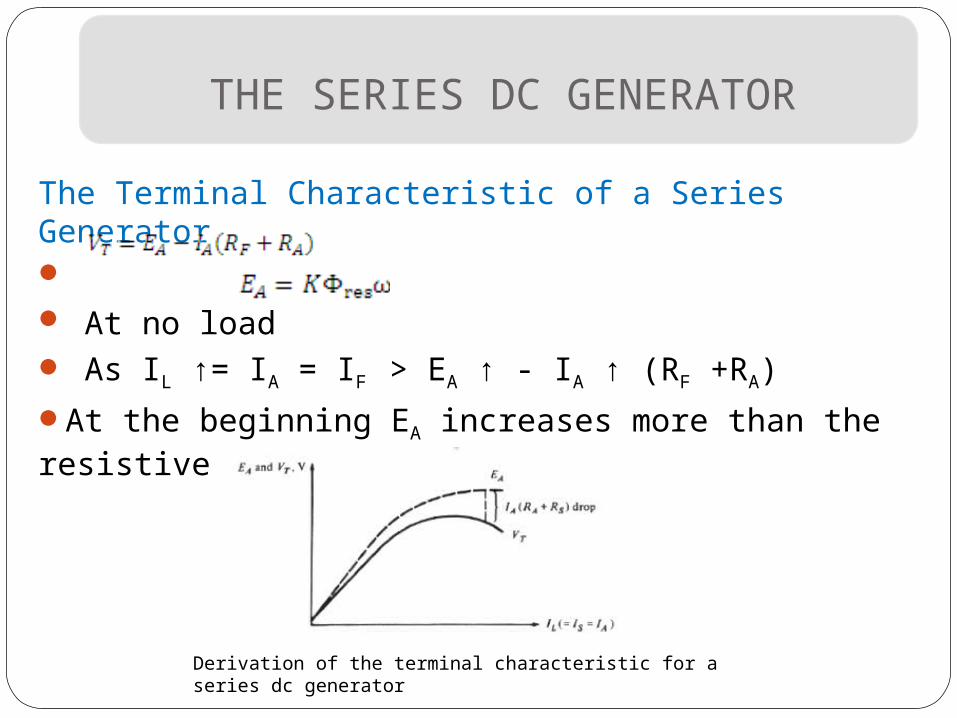
THE SERIES DC GENERATOR
The Terminal Characteristic of a Series Generator At no load As IL ↑= IA = IF > EA ↑ - IA ↑ (RF +RA)
At the beginning EA increases more than the resistive drop
Derivation of the terminal characteristic for a series dc generator
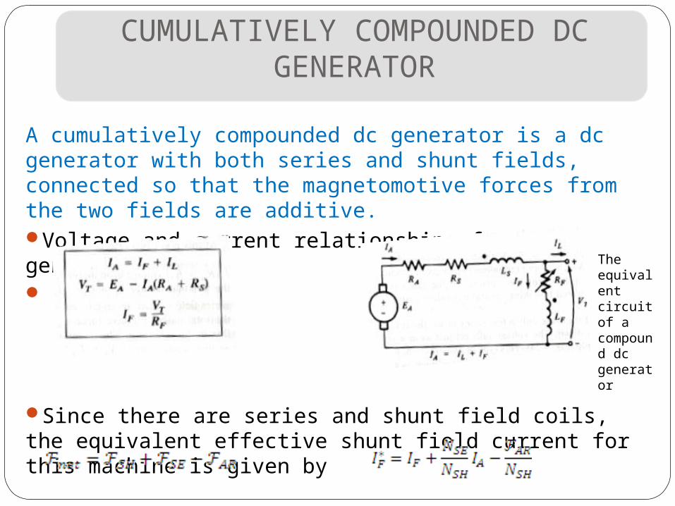
CUMULATIVELY COMPOUNDED DC GENERATOR
A cumulatively compounded dc generator is a dc generator with both series and shunt fields, connected so that the magnetomotive forces from the two fields are additive. Voltage and current relationships for this generator are
Since there are series and shunt field coils, the equivalent effective shunt field current for this machine is given by
The equivalent circuit of a compound dc generator
The Compound Generator
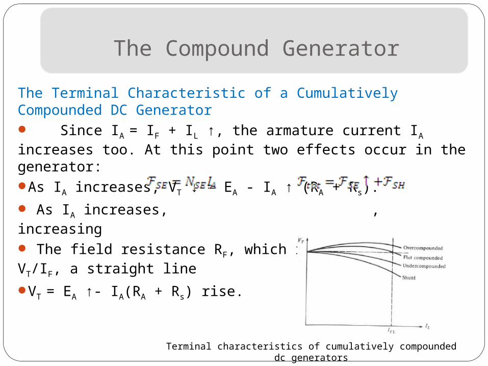
The Terminal Characteristic of a Cumulatively Compounded DC Generator Since IA = IF + IL ↑, the armature current IA increases too. At this point two effects occur in the generator:As IA increases, VT ↓ = EA - IA ↑ (RA + Rs).
As IA increases, , increasing
The field resistance RF, which is just equal to VT/IF, a straight lineVT = EA ↑- IA(RA + Rs) rise.
Terminal characteristics of cumulatively compounded dc generators
The Compound Generator
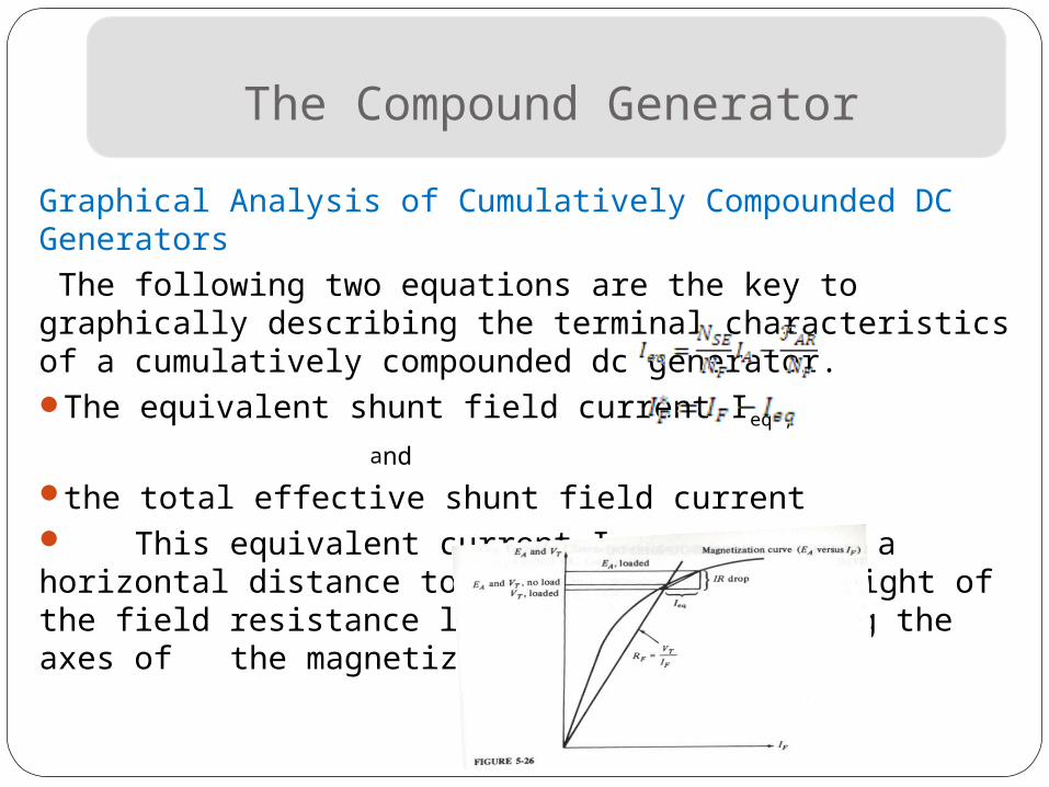
Graphical Analysis of Cumulatively Compounded DC Generators The following two equations are the key to graphically describing the terminal characteristics of a cumulatively compounded dc generator.The equivalent shunt field current Ieq ,
and
the total effective shunt field current This equivalent current Ieq represents a horizontal distance to the left or the right of the field resistance line (RF = VT/IF) along the axes of the magnetization curve.
Recommended