© ECS / Disclosure or duplication without consent is prohibited Author: FEMFAT Support 1 Date:06.04.10
© ECS / Disclosure or duplication without consent is prohibited
OVERVIEW
• Weld seam modeling in FE-Preprocessors
• Weld seam modeling in FEMFAT Visualizer instead
• Fatigue analysis of Weld seams in FEMFAT WELD
(proposed method by Stadler Rail)
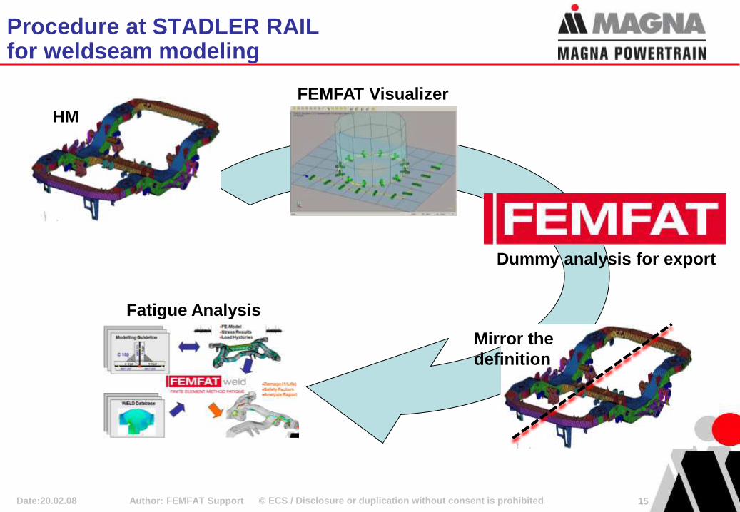
• Procedure at STADLER RAIL for weldseam modeling
– FE meshing in Hypermesh
– Weld seam definition in FEMFAT VISUALIZER – half model
– Dummy analysis for output file
– mirror the definition to the other half (external tool)
– Fatigue analysis with FEMFAT
Author: FEMFAT Support 2 Date:20.02.08
Efficient Modeling and Evaluation of Welding Seams
at Stadler Rail Altenrhein/Switzerland Johann Habenbacher, Stadler Altenrhein AG / Switzerland
Klaus Hofwimmer, Axel Werkhausen, ECS – St. Valentin / Austria
© ECS / Disclosure or duplication without consent is prohibited Author: FEMFAT Support 3 Date:20.02.08
Setup of FE Model
For Example With Shell Elements
Coarse Mesh
Weld seam modeling in FE-Preprocessors
© ECS / Disclosure or duplication without consent is prohibited Author: FEMFAT Support 4 Date:20.02.08
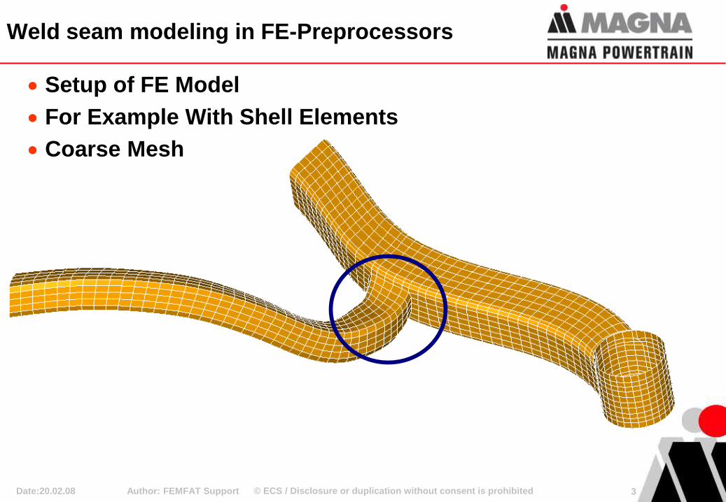
Definition of Weld Seams
According to Modeling Guidelines
Weld Nodes are recognised by Node colour or Coord. System
Weld Type is Recognised by Element ID
No Modification of Material Properties MAT 203
MAT 205
FEMFAT
Model Guidline for
T-joint
Weld seam modeling in FE-Preprocessors
© ECS / Disclosure or duplication without consent is prohibited Author: FEMFAT Support 5 Date:20.02.08
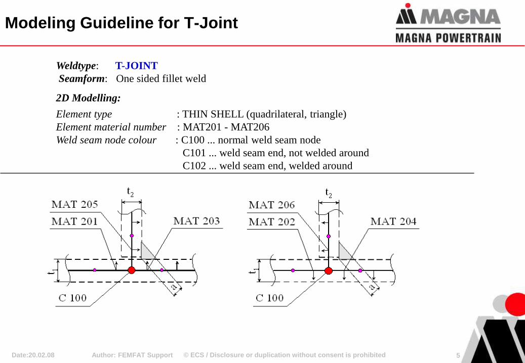
Weldtype: T-JOINT
Seamform: One sided fillet weld
2D Modelling:
Element type : THIN SHELL (quadrilateral, triangle)
Element material number : MAT201 - MAT206
Weld seam node colour : C100 ... normal weld seam node
C101 ... weld seam end, not welded around
C102 ... weld seam end, welded around
Modeling Guideline for T-Joint
© ECS / Disclosure or duplication without consent is prohibited Author: FEMFAT Support 6 Date:20.02.08
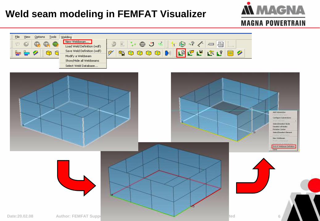
Weld seam modeling in FEMFAT Visualizer
© ECS / Disclosure or duplication without consent is prohibited Author: FEMFAT Support 7 Date:20.02.08
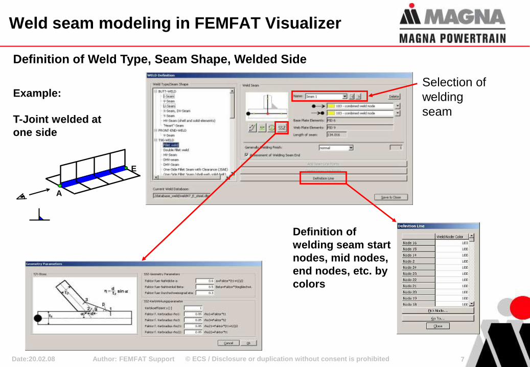
Weld seam modeling in FEMFAT Visualizer
Definition of
welding seam start
nodes, mid nodes,
end nodes, etc. by
colors
A
E
Example:
T-Joint welded at
one side
Selection of
welding
seam
Definition of Weld Type, Seam Shape, Welded Side
© ECS / Disclosure or duplication without consent is prohibited Author: FEMFAT Support 8 Date:20.02.08
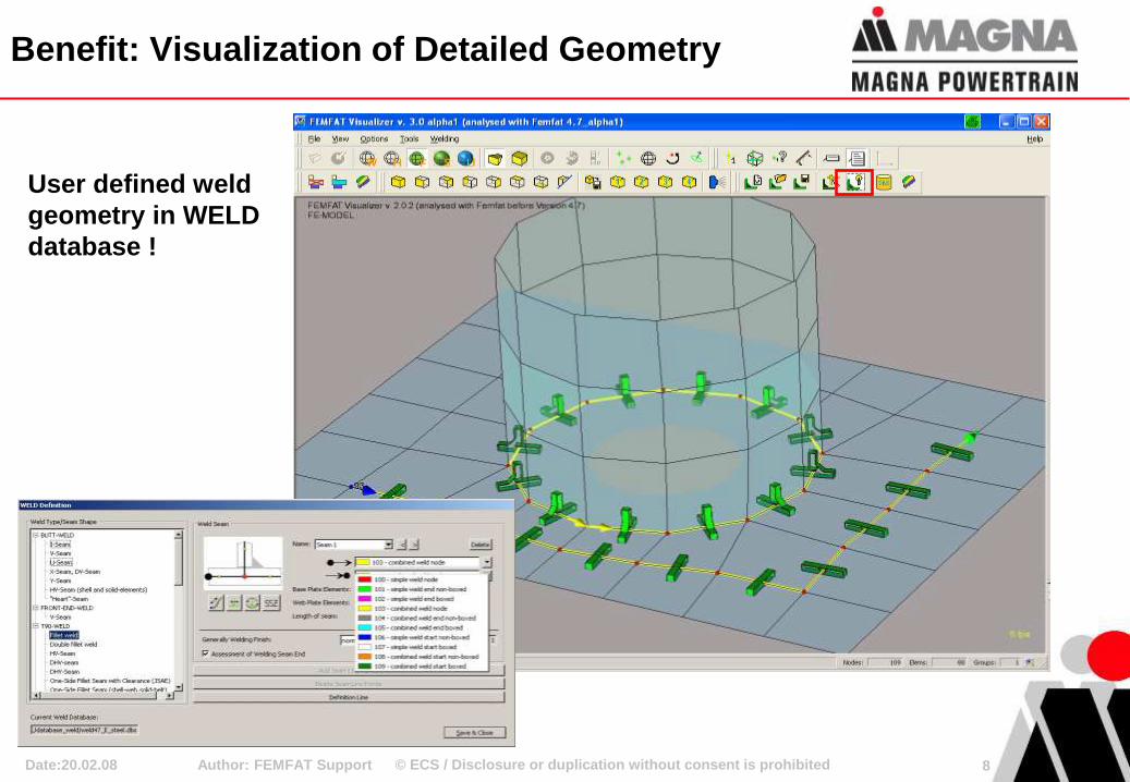
Benefit: Visualization of Detailed Geometry
User defined weld
geometry in WELD
database !
© ECS / Disclosure or duplication without consent is prohibited Author: FEMFAT Support 9
MAT 207 MAT 209
C 100
TOP TOP
TO
P
MA
T 2
11
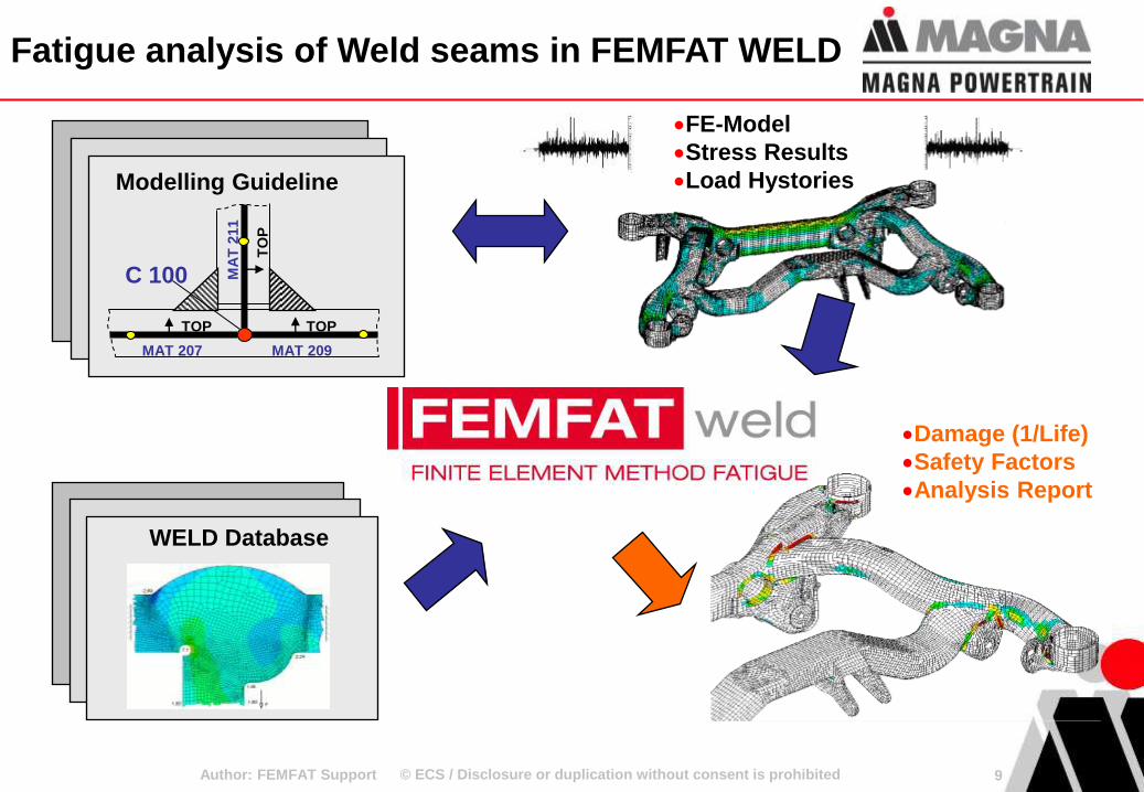
Modelling Guideline
Damage (1/Life)
Safety Factors
Analysis Report
WELD Database
FE-Model
Stress Results
Load Hystories
Fatigue analysis of Weld seams in FEMFAT WELD
© ECS / Disclosure or duplication without consent is prohibited Author: FEMFAT Support 10 Date:20.02.08
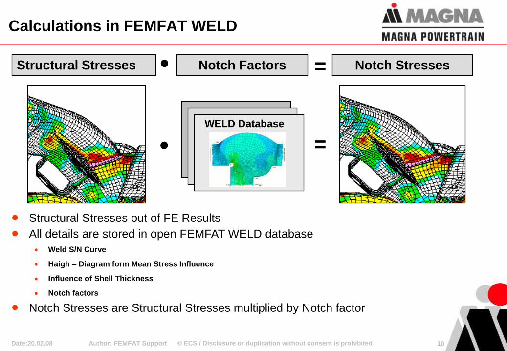
Structural Stresses out of FE Results
All details are stored in open FEMFAT WELD database
Weld S/N Curve
Haigh – Diagram form Mean Stress Influence
Influence of Shell Thickness
Notch factors
Notch Stresses are Structural Stresses multiplied by Notch factor
Structural Stresses Notch Stresses
WELD Database
Notch Factors
=
=
Calculations in FEMFAT WELD
© ECS / Disclosure or duplication without consent is prohibited Author: FEMFAT Support 11 Date:20.02.08
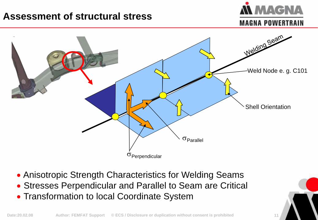
Weld Node e. g. C101
Shell Orientation
sParallel
sPerpendicular
Anisotropic Strength Characteristics for Welding Seams
Stresses Perpendicular and Parallel to Seam are Critical
Transformation to local Coordinate System
Assessment of structural stress
© ECS / Disclosure or duplication without consent is prohibited Author: FEMFAT Support 12 Date:20.02.08
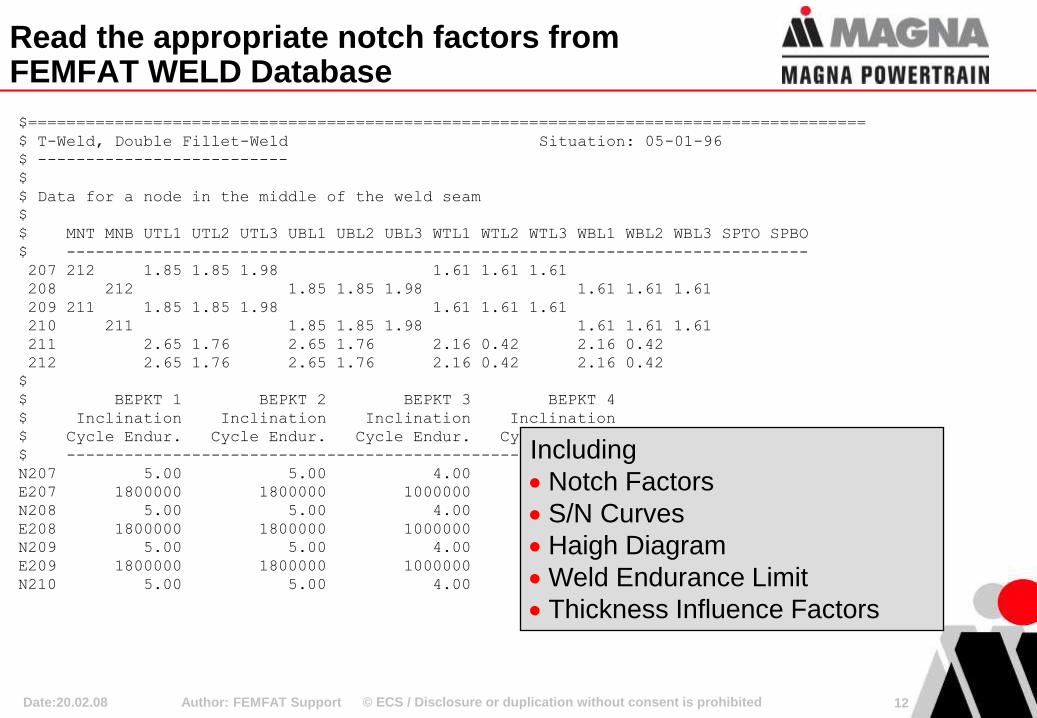
$=======================================================================================
$ T-Weld, Double Fillet-Weld Situation: 05-01-96
$ --------------------------
$
$ Data for a node in the middle of the weld seam
$
$ MNT MNB UTL1 UTL2 UTL3 UBL1 UBL2 UBL3 WTL1 WTL2 WTL3 WBL1 WBL2 WBL3 SPTO SPBO
$ -----------------------------------------------------------------------------
207 212 1.85 1.85 1.98 1.61 1.61 1.61
208 212 1.85 1.85 1.98 1.61 1.61 1.61
209 211 1.85 1.85 1.98 1.61 1.61 1.61
210 211 1.85 1.85 1.98 1.61 1.61 1.61
211 2.65 1.76 2.65 1.76 2.16 0.42 2.16 0.42
212 2.65 1.76 2.65 1.76 2.16 0.42 2.16 0.42
$
$ BEPKT 1 BEPKT 2 BEPKT 3 BEPKT 4
$ Inclination Inclination Inclination Inclination
$ Cycle Endur. Cycle Endur. Cycle Endur. Cycle Endur.
$ -------------------------------------------------------------------
N207 5.00 5.00 4.00 4.00
E207 1800000 1800000 1000000 1000000
N208 5.00 5.00 4.00 4.00
E208 1800000 1800000 1000000 1000000
N209 5.00 5.00 4.00 4.00
E209 1800000 1800000 1000000 1000000
N210 5.00 5.00 4.00 4.00
Including
Notch Factors
S/N Curves
Haigh Diagram
Weld Endurance Limit
Thickness Influence Factors
Read the appropriate notch factors from FEMFAT WELD Database
© ECS / Disclosure or duplication without consent is prohibited Author: FEMFAT Support 13 Date:20.02.08
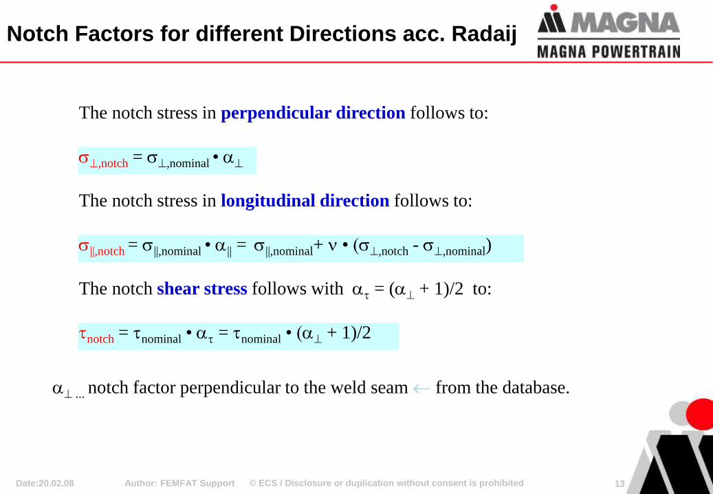
Notch Factors for different Directions acc. Radaij
... notch factor perpendicular to the weld seam from the database.
The notch stress in perpendicular direction follows to:
s,notch = s,nominal •
The notch stress in longitudinal direction follows to:
s||,notch = s||,nominal • || = s||,nominal+ • (s,notch - s,nominal)
The notch shear stress follows with = ( + 1)/2 to:
notch = nominal • = nominal • ( + 1)/2
© ECS / Disclosure or duplication without consent is prohibited
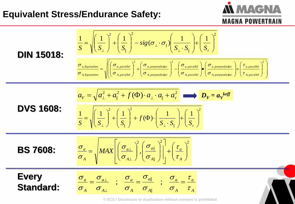
Equivalent Stress/Endurance Safety:
2
||
2
||
2 )( aaafaaaV DV = aVkeff
2
||
2
||
2
11)(
111
SSSf
SSS
DVS 1608:
A
a
A
a
A
a
A
a
A
a
A
a
s
s
s
s
s
s
s
s
s
s
;;||
||Every
Standard:
2
,
,
,
,
,
,
2
,
,
2
,
,
,
,
parallelA
parallela
larperpendicuA
larperpendicua
parallelA
parallela
larperpendicuA
larperpendicua
parallelA
parallela
EquivalentA
Equivalenta
s
s
s
s
s
s
s
s
s
s
DIN 15018:
2
||
||
2
||
2
11)(
111
ssSSS
sigSSS
22
||
||
2
,
A
a
A
a
A
a
A
a MAX
s
s
s
s
s
sBS 7608:
© ECS / Disclosure or duplication without consent is prohibited
Procedure at STADLER RAIL for weldseam modeling
Author: FEMFAT Support 15 Date:20.02.08
HM
FEMFAT Visualizer
Dummy analysis for export
Mirror the
definition
Fatigue Analysis
© ECS / Disclosure or duplication without consent is prohibited
Conclusion
• Stadler Rail limits the time for weldseam modeling to
about 60%
• Additional time for the dummy analysis is small.
• The script for mirroring the definitions from ALTAIR was
worth the money within the second project.
• The fatigue results on the complete structure (symmetric
results for symmetric loads) make the railway authorities
happy.
Author: FEMFAT Support 16 Date:20.02.08

© ECS / Disclosure or duplication without consent is prohibited
Loadcase definition and combination
Author: FEMFAT Support 17 Date:20.02.08
Recommended