© 2015| All right reserved 84
Int. Res. J. of Science & Engineering, 2015; Vol. 3 (3): 84-92 ISSN: 2322-0015
Data Transmission By Using Light Fidelity
Tirmanwar SL1 , Bhalerao MV2 and Nemmaniwar BG*
1Department of Electronics and Telecommunication, SGGSIE&T, Nanded (MS), India.
2Department of Electronics and Telecommunication, SGGSIE&T, Nanded (MS), India.
3Department of Physics, D.B. College, Bhokar, Nanded (MS), India.
*Corresponding author : Dr. Nemmaniwar BG. Assistant Professor & Head, Department of Physics, D.B.
College, Bhokar, Nanded (MS), India Email : [email protected]
Manuscript Details ABSTRACT
Received : 06.04.2015
Revised : 01.05.2015
Re- Revised: 15.05.2015
Accepted: 14.06.2015
Published: 28.06.2015
ISSN: 2322-0015
Editor: Dr. Arvind Chavhan
Cite this article as:
Tirmanwar SL, Bhalerao MV and
Nemmaniwar BG. Data
Transmission By Using Light
Fidelity Int. Res. J. of Science &
Engineering, 2015; Vol. 3 (3):84-
92.
Copyright: © Author(s), This is
an open access article under the
terms of the Creative Commons
Attribution Non-Commercial No
Derivs License, which permits use
and distribution in any medium,
provided the original work is
properly cited, the use is non-
commercial and no modifications
or adaptations are made.
Light Fidelity means the wireless data transfer using LED. The
main concept behind this Li-Fi is “Data through Illumination”. It
transmits data with the help of an LED bulb having variation in its
intensity which has a speed of actually faster than which human
eye can follow. It is also known as optical wireless technology or
visible light communication. The paper discusses about an
apparatus consisting of a transmitter which includes a light source
and the receiver circuit which receives the data transmitted via
light waves. To convert data to be transmitted in the form of light
waves we used a processor MSP430G2553.
Keywords: LCD, IAR, IDE, CCS, DIP, ADC, Li-Fi, Wi-Fi, UART
Abbrevation:
LCD : Liquefied Crystal Display.
IAR :Ingenjorsfirman Anders Rundgren
IDE : Integrated Development Environment.
CCS : Code Composer Studio.
DIP : Dual In-Line Package.
ADC : Analog to Digital Converter.
Li-Fi : Light Fidelity.
Wi-Fi : Wireless Fidelity.
UART : Universal Asynchronous Receiver and Transmitter.
INTRODUCTION
The transmission by using Light Fidelity is mainly based on
blinking of LED. If the LED is ON, you are transmitting the data
OPEN ACCESS
RESEARCH ARTICLE
Data Transmission By Using Light Fidelity
Int. Res. J. of Science & Engineering, 2015; Volume 3, No. 3, May-June, 2015. 85
means you transmit a digital 1; and if the LED is
OFF you transmit a digital 0 or null or simply no
data transfer happens (Ekta and Kaur, 2014). As
one can switch them on and off very frequently
one can transmit data easily because the LEDs
intensity is modulated so rapidly that human eye
cannot notice, so the output in form of light
appears constant and hence offering permanent
connectivity. More sophistication in the
transmission techniques can further increase the
data rates through VLC (Jadhav, 2014; Condliffe,
2011).
To convert data in the form of digital signals 1 and
0 we used a processor MSP430G2553. The MSP-
EXP430G2553 Launch Pad is an inexpensive and
simple evaluation kit for the MSP430G2xx Value
Line series of microcontrollers. It is an easy way to
start developing on the MSP430 with on-board
emulation for programming and debugging as well
as buttons and LEDs for a simple user interface.
Rapid prototyping is simplified by the 20-pin
Booster Pack headers which support a wide range
of available Booster Pack plug-in modules. You can
quickly add features like wireless connectivity,
graphical displays, environmental sensing, and
much more. You can either design your own
Booster Pack or choose among many already
available from TI. The Launch Pad features an
integrated DIP target socket that supports up to
20 pins, allowing MSP430 Value Line devices to be
plugged into the Launch Pad board. The MSP-
EXP430G2553 Launch Pad comes with an
MSP430G2553 device by default.
The MSP430G2553 has the most memory
available of the compatible Value Line devices. The
MSP430G2553 16-bit MCU has 16KB flash, 512
bytes RAM, up to 16-MHz CPU speed, 10-bit ADC,
capacitive touch enabled I/Os, universal serial
communication interface, and more – plenty to get
you started in your development. Free software
development tools are also available: TI's Eclipse-
based Code Composer Studio IDE (CCS), IAR
Embedded Workbench IDE (IAR), and the
community-driven Energia open source code
editor (http://ti.com/product/msp430g2553 ).
MATERIALS AND METHODS
Hardware:
MSP430G2553 launch pad kit, LPC2148 Arm
processor kit, LED, Photo Diode (BPW34), Current
Amplifier (current gain >50), Transistor BC547,
Wires.
Software:
CCS (code composer studio 4thversion), Side Arm,
Flash Magic.
The Li-Fi technology basically is a process of data
transmission through led that is wireless data
transfer through led. It consists of two stages;
transmitter and receiver (http://en.wikipedia.org-
/wiki/Li-Fi). In the transmitter circuit, the input is
given from the laptop with the help of USB cable
connected to MSP430 via the UART transmission
process coded using Code Compose Studio
software. Initially, in MSP430 processor the
output is set at TxD pin. The text sent using UART
to MSP430 is processed as MSP430 is a digital
signal processor it gives output in the form of
digital signal means in the form of 1 and 0 which
are called as digital signals. The output of MSP430
from TxD pin is given as input to the transmitter
part. The interesting part of this whole project is
that the some part of transmitter and receiver
circuit is almost same for both music and data
transfer. After getting input from MSP430
transmitter part start transmitting in the coded
text in the form of LED blinking. As the time delay
is very negligible LED blinks very rapidly. The
Photo diode in the same circuit receives the signal
transmitted in the form of LED blinking and
output of diode sent as input to the receiver circuit
(Goyal et al., 2013). The distance through which
the blinking can be detected depends on the photo
diode, the higher the quality of photo diode the
larger will be the distance through which the
blinking will be detected.
This wireless transmission using LED blinking
consist 802.11 wireless protocol as same as Wi-Fi.
The receiver circuit consists of simple ARM
processor kit, here we used LPC2148 kit. The
LPC2148 uses UART for serial communication
Tirmanwar et al., 2015
86 www.irjse.in
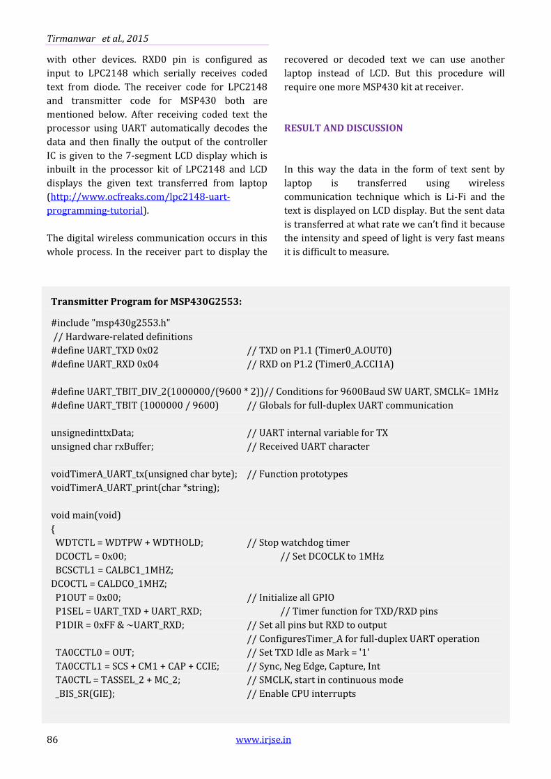
with other devices. RXD0 pin is configured as
input to LPC2148 which serially receives coded
text from diode. The receiver code for LPC2148
and transmitter code for MSP430 both are
mentioned below. After receiving coded text the
processor using UART automatically decodes the
data and then finally the output of the controller
IC is given to the 7-segment LCD display which is
inbuilt in the processor kit of LPC2148 and LCD
displays the given text transferred from laptop
(http://www.ocfreaks.com/lpc2148-uart-
programming-tutorial).
The digital wireless communication occurs in this
whole process. In the receiver part to display the
recovered or decoded text we can use another
laptop instead of LCD. But this procedure will
require one more MSP430 kit at receiver.
RESULT AND DISCUSSION
In this way the data in the form of text sent by
laptop is transferred using wireless
communication technique which is Li-Fi and the
text is displayed on LCD display. But the sent data
is transferred at what rate we can’t find it because
the intensity and speed of light is very fast means
it is difficult to measure.
Transmitter Program for MSP430G2553:
#include "msp430g2553.h"
// Hardware-related definitions
#define UART_TXD 0x02 // TXD on P1.1 (Timer0_A.OUT0)
#define UART_RXD 0x04 // RXD on P1.2 (Timer0_A.CCI1A)
#define UART_TBIT_DIV_2(1000000/(9600 * 2))// Conditions for 9600Baud SW UART, SMCLK= 1MHz
#define UART_TBIT (1000000 / 9600) // Globals for full-duplex UART communication
unsignedinttxData; // UART internal variable for TX
unsigned char rxBuffer; // Received UART character
voidTimerA_UART_tx(unsigned char byte); // Function prototypes
voidTimerA_UART_print(char *string);
void main(void)
{
WDTCTL = WDTPW + WDTHOLD; // Stop watchdog timer
DCOCTL = 0x00; // Set DCOCLK to 1MHz
BCSCTL1 = CALBC1_1MHZ;
DCOCTL = CALDCO_1MHZ;
P1OUT = 0x00; // Initialize all GPIO
P1SEL = UART_TXD + UART_RXD; // Timer function for TXD/RXD pins
P1DIR = 0xFF & ~UART_RXD; // Set all pins but RXD to output
// ConfiguresTimer_A for full-duplex UART operation
TA0CCTL0 = OUT; // Set TXD Idle as Mark = '1'
TA0CCTL1 = SCS + CM1 + CAP + CCIE; // Sync, Neg Edge, Capture, Int
TA0CTL = TASSEL_2 + MC_2; // SMCLK, start in continuous mode
_BIS_SR(GIE); // Enable CPU interrupts

Data Transmission By Using Light Fidelity
Int. Res. J. of Science & Engineering, 2015; Volume 3, No. 3, May-June, 2015. 87
TimerA_UART_print("HELLO WORLD\r\n"); // Send text message
TimerA_UART_print("READY.\r\n");
while(1)
{ // Wait for incoming character
_BIS_SR(LPM0_bits); // Enter low poser mode
TimerA_UART_tx(rxBuffer); // Transmit the received data
}
}
voidTimerA_UART_tx(unsigned char byte)
{
// Outputs one byte using the Timer_A UART
while (TACCTL0 & CCIE); // Ensure last char got TX'd
TA0CCR0 = TAR; // Current state of TA counter
TA0CCR0 += UART_TBIT; // One bit time till first bit
TA0CCTL0 = OUTMOD0 + CCIE; // Set TXD on EQU0, Int
txData = byte; // Load global variable
txData |= 0x100; // Add mark stop bit to TXData
txData<<= 1; // Add space start bit
}
voidTimerA_UART_print(char *string)
{
// Prints a string using the Timer_A UART
while (*string)
TimerA_UART_tx(*string++);
}
#pragma vector = TIMER0_A0_VECTOR // Timer_A UART - Transmit Interrupt Handler
__interrupt void Timer_A0_ISR(void)
{
static unsigned char txBitCnt = 10;
TA0CCR0 += UART_TBIT; // Add Offset to CCRx
if (txBitCnt == 0)
{ // All bits TXed?
TA0CCTL0 &= ~CCIE; // All bits TXed, disable interrupt
txBitCnt = 10; // Re-load bit counter
}
else
{
if (txData& 0x01)
TA0CCTL0 &= ~OUTMOD2; // TX Mark '1'
else
TA0CCTL0 |= OUTMOD2; // TX Space '0'
}
txData>>= 1; // Shift right 1 bit
txBitCnt--;
Tirmanwar et al., 2015
88 www.irjse.in
}
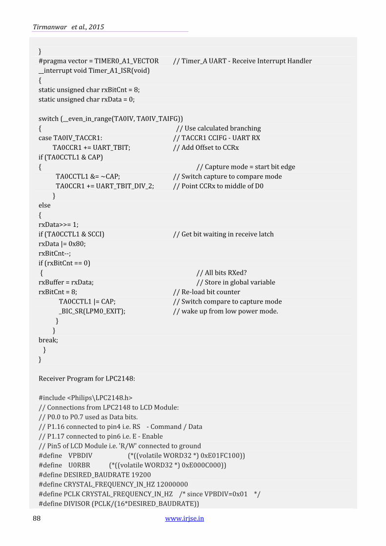
#pragma vector = TIMER0_A1_VECTOR // Timer_A UART - Receive Interrupt Handler
__interrupt void Timer_A1_ISR(void)
{
static unsigned char rxBitCnt = 8;
static unsigned char rxData = 0;
switch (__even_in_range(TA0IV, TA0IV_TAIFG))
{ // Use calculated branching
case TA0IV_TACCR1: // TACCR1 CCIFG - UART RX
TA0CCR1 += UART_TBIT; // Add Offset to CCRx
if (TA0CCTL1 & CAP)
{ // Capture mode = start bit edge
TA0CCTL1 &= ~CAP; // Switch capture to compare mode
TA0CCR1 += UART_TBIT_DIV_2; // Point CCRx to middle of D0
}
else
{
rxData>>= 1;
if (TA0CCTL1 & SCCI) // Get bit waiting in receive latch
rxData |= 0x80;
rxBitCnt--;
if (rxBitCnt == 0)
{ // All bits RXed?
rxBuffer = rxData; // Store in global variable
rxBitCnt = 8; // Re-load bit counter
TA0CCTL1 |= CAP; // Switch compare to capture mode
_BIC_SR(LPM0_EXIT); // wake up from low power mode.
}
}
break;
}
}
Receiver Program for LPC2148:
#include <Philips\LPC2148.h>
// Connections from LPC2148 to LCD Module:
// P0.0 to P0.7 used as Data bits.
// P1.16 connected to pin4 i.e. RS - Command / Data
// P1.17 connected to pin6 i.e. E - Enable
// Pin5 of LCD Module i.e. 'R/W' connected to ground
#define VPBDIV (*((volatile WORD32 *) 0xE01FC100))
#define U0RBR (*((volatile WORD32 *) 0xE000C000))
#define DESIRED_BAUDRATE 19200
#define CRYSTAL_FREQUENCY_IN_HZ 12000000
#define PCLK CRYSTAL_FREQUENCY_IN_HZ /* since VPBDIV=0x01 */
#define DIVISOR (PCLK/(16*DESIRED_BAUDRATE))
Data Transmission By Using Light Fidelity
Int. Res. J. of Science & Engineering, 2015; Volume 3, No. 3, May-June, 2015. 89
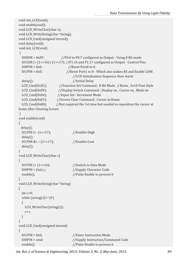
void init_LCD(void);
void enable(void);
void LCD_WriteChar(char c);
void LCD_WriteString(char *string);
void LCD_Cmd(unsigned intcmd);
void delay(void);
void init_LCD(void)
{
IO0DIR = 0xFF; //P0.0 to P0.7 configured as Output - Using 8 Bit mode
IO1DIR |= (1<<16) | (1<<17); //P1.16 and P1.17 configured as Output - Control Pins
IO0PIN = 0x0; //Reset Port0 to 0.
IO1PIN = 0x0; //Reset Port1 to 0 - Which also makes RS and Enable LOW.
//LCD Initialization Sequence Now starts
delay(); //Initial Delay
LCD_Cmd(0x3C); //Function Set Command : 8 Bit Mode , 2 Rows , 5x10 Font Style
LCD_Cmd(0x0F); //Display Switch Command : Display on , Cursor on , Blink on
LCD_Cmd(0x06); //Input Set : Increment Mode
LCD_Cmd(0x01); //Screen Clear Command , Cursor at Home
LCD_Cmd(0x80); //Not required the 1st time but needed to reposition the cursor at
home after Clearing Screen
}
void enable(void)
{
delay();
IO1PIN |= (1<<17); //Enable=High
delay();
IO1PIN &= ~(1<<17); //Enable=Low
delay();
}
void LCD_WriteChar(char c)
{
IO1PIN |= (1<<16); //Switch to Data Mode
IO0PIN = (int) c; //Supply Character Code
enable(); //Pulse Enable to process it
}
void LCD_WriteString(char *string)
{
int c=0;
while (string[c]!='\0')
{
LCD_WriteChar(string[c]);
c++;
}
}
void LCD_Cmd(unsigned intcmd)
{
IO1PIN = 0x0; //Enter Instruction Mode
IO0PIN = cmd; //Supply Instruction/Command Code
enable(); //Pulse Enable to process it
Tirmanwar et al., 2015
90 www.irjse.in
}
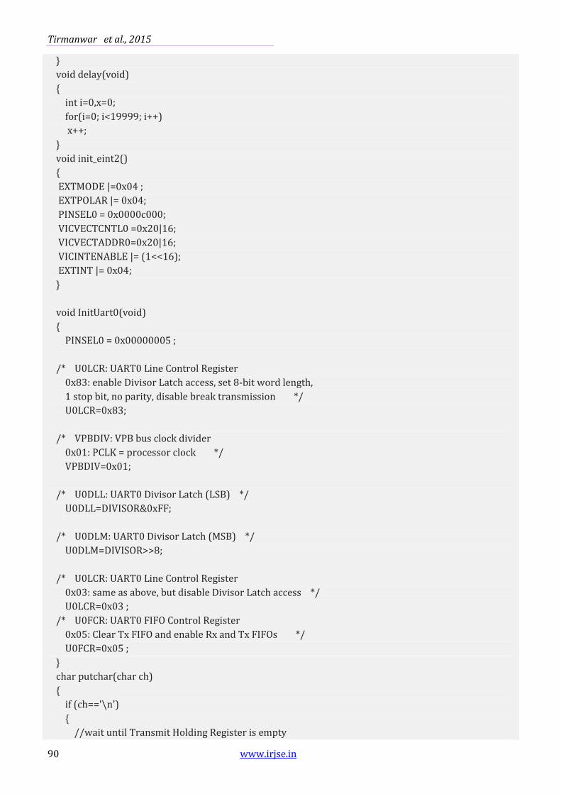
void delay(void)
{
int i=0,x=0;
for(i=0; i<19999; i++)
x++;
}
void init_eint2()
{
EXTMODE |=0x04 ;
EXTPOLAR |= 0x04;
PINSEL0 = 0x0000c000;
VICVECTCNTL0 =0x20|16;
VICVECTADDR0=0x20|16;
VICINTENABLE |= (1<<16);
EXTINT |= 0x04;
}
void InitUart0(void)
{
PINSEL0 = 0x00000005 ;
/* U0LCR: UART0 Line Control Register
0x83: enable Divisor Latch access, set 8-bit word length,
1 stop bit, no parity, disable break transmission */
U0LCR=0x83;
/* VPBDIV: VPB bus clock divider
0x01: PCLK = processor clock */
VPBDIV=0x01;
/* U0DLL: UART0 Divisor Latch (LSB) */
U0DLL=DIVISOR&0xFF;
/* U0DLM: UART0 Divisor Latch (MSB) */
U0DLM=DIVISOR>>8;
/* U0LCR: UART0 Line Control Register
0x03: same as above, but disable Divisor Latch access */
U0LCR=0x03 ;
/* U0FCR: UART0 FIFO Control Register
0x05: Clear Tx FIFO and enable Rx and Tx FIFOs */
U0FCR=0x05 ;
}
char putchar(char ch)
{
if (ch=='\n')
{
//wait until Transmit Holding Register is empty
Data Transmission By Using Light Fidelity
Int. Res. J. of Science & Engineering, 2015; Volume 3, No. 3, May-June, 2015. 91
while (!(U0LSR&0x20)) {
//then store to Transmit Holding Register
U0THR='\r';
}
//wait until Transmit Holding Register is empty
while (!(U0LSR&0x20)) {}
//then store to Transmit Holding Register
U0THR=ch;
return ch;
}
char eint2(void)__attribute__(interrupt ("IRQ"))
//Task after the interrupt generation
{
charch;
//wait until there's a character to be read
while (!(U0LSR & 0x01))
{
}
//then read from the Receiver Buffer Register
ch=U0RBR;
return ch;
}
int main(void)
{
char ch;
init_eint2();
init_LCD(); //LCD Now intialized and ready to Print!
LCD_WriteString(&ch);
LCD_Cmd(0x80 + 0x40); //Come to 2nd Row
while(1); // Loop forever
return 0; //This won't execute :P
}
CONCLUSION
This experiment is done at very small level but he
possibilities are numerous and can be explored
further. If his technology can be put into practical
use, every bulb can be used something like a Wi-Fi
hotspot to transmit wireless data and we will
proceed toward the cleaner, greener, safer and
brighter future.The concept of Li-Fi is currently
attracting a great deal of interest, not least
because it may offer a genuine and very efficient
alternative to radio-based wireless. As a growing
number of people and their many devices access
wireless internet, the airwaves are becoming
increasingly clogged, making it more and more
difficult to get a reliable, high-speed signal. This
may solve issues such as the shortage of radio-
frequency bandwidth and also allow internet
where traditional radio based wireless isn’t
allowed such as aircraft or hospitals. One of the
shortcomings however is that it only work in
direct line of sight(Rani et al, 2012).
Tirmanwar et al., 2015
92 www.irjse.in
REFERENCES
1. Ekta and Ranjeet Kaur. Light Fidelity(Li-Fi)-A
Comprehensive Study. Inter. J. Comp. Sci. &
Mob. Computing., April 2014; 3(4): 2-3.
2. Jadhav VA. study on Li-Fi-Light Fidelity. Inter.
J. Sci. & Engg. Res., June 2014; 5(6): 1.
3. Condliffe J Will .Li-Fi be the new Wi-Fi?. New
Scientist. 28 July 2011.
4. http://ti.com/product/msp430g2553.
5. http://en.wikipedia.org/wiki/Li-Fi.
6. Goyal M, Saproo D, Bhagashra A. New Epoch of
Wireless Communication: Light Fidelity. Inter.
J. Inno. Res. Comp. & Comm. Engg., April 2013;
1(2): 3.
7. http://www.ocfreaks.com/lpc2148-uart-
programming-tutorial/.
8. Rani J, Chauhan P, Tripathi R. Li-Fi(Light
Fidelity)-The future technology In Wireless
communication. Inter. J. Appl. Engg. Res., 2012;
7(11): 1-4.
© 2015| Published by IRJSE
Recommended